EP4200946B1 - Pince manuelle conçue pour réaliser un sertissage et pince manuelle pourvue d'une tête de pince - Google Patents
Pince manuelle conçue pour réaliser un sertissage et pince manuelle pourvue d'une tête de pince Download PDFInfo
- Publication number
- EP4200946B1 EP4200946B1 EP21766141.2A EP21766141A EP4200946B1 EP 4200946 B1 EP4200946 B1 EP 4200946B1 EP 21766141 A EP21766141 A EP 21766141A EP 4200946 B1 EP4200946 B1 EP 4200946B1
- Authority
- EP
- European Patent Office
- Prior art keywords
- crimping
- jaw
- pliers
- hand pliers
- jaws
- Prior art date
- Legal status (The legal status is an assumption and is not a legal conclusion. Google has not performed a legal analysis and makes no representation as to the accuracy of the status listed.)
- Active
Links
Images





Classifications
-
- B—PERFORMING OPERATIONS; TRANSPORTING
- B25—HAND TOOLS; PORTABLE POWER-DRIVEN TOOLS; MANIPULATORS
- B25B—TOOLS OR BENCH DEVICES NOT OTHERWISE PROVIDED FOR, FOR FASTENING, CONNECTING, DISENGAGING, OR HOLDING
- B25B27/00—Hand tools, specially adapted for fitting together or separating parts or objects whether or not involving some deformation, not otherwise provided for
- B25B27/14—Hand tools, specially adapted for fitting together or separating parts or objects whether or not involving some deformation, not otherwise provided for for assembling objects other than by press fit or detaching same
- B25B27/146—Clip clamping hand tools
-
- B—PERFORMING OPERATIONS; TRANSPORTING
- B25—HAND TOOLS; PORTABLE POWER-DRIVEN TOOLS; MANIPULATORS
- B25B—TOOLS OR BENCH DEVICES NOT OTHERWISE PROVIDED FOR, FOR FASTENING, CONNECTING, DISENGAGING, OR HOLDING
- B25B7/00—Pliers; Other hand-held gripping tools with jaws on pivoted limbs; Details applicable generally to pivoted-limb hand tools
- B25B7/02—Jaws
-
- B—PERFORMING OPERATIONS; TRANSPORTING
- B25—HAND TOOLS; PORTABLE POWER-DRIVEN TOOLS; MANIPULATORS
- B25B—TOOLS OR BENCH DEVICES NOT OTHERWISE PROVIDED FOR, FOR FASTENING, CONNECTING, DISENGAGING, OR HOLDING
- B25B7/00—Pliers; Other hand-held gripping tools with jaws on pivoted limbs; Details applicable generally to pivoted-limb hand tools
- B25B7/12—Pliers; Other hand-held gripping tools with jaws on pivoted limbs; Details applicable generally to pivoted-limb hand tools involving special transmission means between the handles and the jaws, e.g. toggle levers, gears
-
- B—PERFORMING OPERATIONS; TRANSPORTING
- B25—HAND TOOLS; PORTABLE POWER-DRIVEN TOOLS; MANIPULATORS
- B25B—TOOLS OR BENCH DEVICES NOT OTHERWISE PROVIDED FOR, FOR FASTENING, CONNECTING, DISENGAGING, OR HOLDING
- B25B7/00—Pliers; Other hand-held gripping tools with jaws on pivoted limbs; Details applicable generally to pivoted-limb hand tools
- B25B7/14—Locking means
-
- H—ELECTRICITY
- H01—ELECTRIC ELEMENTS
- H01R—ELECTRICALLY-CONDUCTIVE CONNECTIONS; STRUCTURAL ASSOCIATIONS OF A PLURALITY OF MUTUALLY-INSULATED ELECTRICAL CONNECTING ELEMENTS; COUPLING DEVICES; CURRENT COLLECTORS
- H01R43/00—Apparatus or processes specially adapted for manufacturing, assembling, maintaining, or repairing of line connectors or current collectors or for joining electric conductors
- H01R43/04—Apparatus or processes specially adapted for manufacturing, assembling, maintaining, or repairing of line connectors or current collectors or for joining electric conductors for forming connections by deformation, e.g. crimping tool
- H01R43/042—Hand tools for crimping
- H01R43/0421—Hand tools for crimping combined with other functions, e.g. cutting
-
- H—ELECTRICITY
- H02—GENERATION; CONVERSION OR DISTRIBUTION OF ELECTRIC POWER
- H02G—INSTALLATION OF ELECTRIC CABLES OR LINES, OR OF COMBINED OPTICAL AND ELECTRIC CABLES OR LINES
- H02G1/00—Methods or apparatus specially adapted for installing, maintaining, repairing or dismantling electric cables or lines
- H02G1/12—Methods or apparatus specially adapted for installing, maintaining, repairing or dismantling electric cables or lines for removing insulation or armouring from cables, e.g. from the end thereof
- H02G1/1202—Methods or apparatus specially adapted for installing, maintaining, repairing or dismantling electric cables or lines for removing insulation or armouring from cables, e.g. from the end thereof by cutting and withdrawing insulation
- H02G1/1204—Hand-held tools
- H02G1/1207—Hand-held tools the cutting element not rotating about the wire or cable
- H02G1/1209—Hand-held tools the cutting element not rotating about the wire or cable making a transverse cut
- H02G1/1212—Hand-held tools the cutting element not rotating about the wire or cable making a transverse cut using wire or cable clamping means
Definitions
- Hand tools of the type in question are known, in particular for use as so-called crimping pliers for crimping or pressing pressed parts, such as wire end ferrules onto stripped ends of electrical cables.
- crimping pliers for crimping or pressing pressed parts, such as wire end ferrules onto stripped ends of electrical cables.
- DE 10 2018 101 159 A1 referred to.
- a pliers-like hand tool designed as a crimping tool in which a movable crimping jaw can be moved linearly relative to a stationary crimping jaw for crimping.
- a locator can be provided associated with the stationary crimping jaw, wherein the locator is movable against a compression spring.
- a hand tool that features a fixed and a pivoting crimping jaw.
- the hand tool is designed for crimping only.
- the object of the invention is to advantageously design a hand tool as described with a design which is advantageous in terms of handling.
- first and the second crimping jaw are provided with partially comb-like interlocking ribs which are triangular in shape when viewed in the direction of insertion of a cable provided with a pressing into a crimping opening, wherein in an unloaded basic position a crimping mouth which is rectangular in plan is produced, that the second crimping jaw can be moved back against spring force in a crimping jaw receptacle of the hand tool and that the first and the second crimping jaw are arranged in a common linear guide.
- the spring force can be applied directly by the second crimping jaw, in particular by a section of the second crimping jaw, or alternatively by a separate part.
- the second Crimping jaw can have a correspondingly acting, further, for example, molded-on spring element directly or indirectly.
- the spring element applying the spring force can be a separate element from the second crimping jaw, for example a metal or plastic spring, e.g. in the form of a cylindrical compression spring or a leg spring.
- a plastic spring in the form of an elastically compressible and reboundable solid element further, for example, in the form of a foam element, is preferred.
- a polyurethane block element can serve as the spring element against which the second crimping jaw acts, in particular during crimping.
- the return movement or evasive movement of the second crimping jaw makes possible against spring force during crimping, enables the pressing of compacts of different extension dimensions (if applicable, diameter) viewed in the direction of displacement, with an essentially constant displacement path of the movable pliers leg, which acts in particular on the first crimping jaw, preferably indirectly via the drive plunger. Accordingly, the user is provided with an at least approximately constant actuation path of the hand pliers, particularly regardless of the diameter of the compact to be crimped, for example a wire end ferrule.
- the different displacement distances, in particular of the first crimping jaw, which arise depending on, for example, the diameter of the compact, are made possible by the second crimping jaw being movable back against the spring force.
- the spring therefore preferably has a distance-compensating effect.
- a crimping area is created that is assigned to either the underside or the top side of the hand tool. This allows a cable with a wire end ferrule in the area of a stripped end to be inserted into the crimping area of the hand tool in a convenient manner, with the cable end pointing essentially vertically upwards with the wire end ferrule attached.
- the desired crimp is then achieved by actuating the pliers' arms in a pliers-like manner.
- the hand tool is in the orientation that corresponds to normal handling.
- the first and second crimping jaws are arranged in a common linear guide.
- the linear guide can optionally also form the crimping jaw receptacle for the second crimping jaw.
- the drive plunger which is preferably connected to the movable pliers leg or acted upon via the movable pliers leg, accordingly preferably acts in a linearly displacing manner on the first crimping jaw, wherein during crimping via the first crimping jaw and the compact, the second crimping jaw can optionally also be displaced against the spring force within the linear guide.
- the linear guide can be formed by structural means directly within the hand tool, in particular a housing of the hand tool.
- this can result, for example, in a bilateral lateral guide, preferably for both crimping jaws, more preferably a guide that essentially surrounds the entire circumference of the crimping jaws.
- the hand pliers are designed as stripping pliers, whereby the same hand pliers can first be used to strip the insulation of a free cable end and then to crimp this stripped cable end with, for example, a wire end ferrule.
- the pliers legs can, according to a possible further development, interact via a positive lock.
- This positive lock preferably allows, during pliers operation, the movement, in particular pivoting movement, of the movable pliers leg only in one direction, namely preferably the pliers closing direction, up to a pliers leg position in which the crimping and/or the stripping is safely completed. Only then does the positive locking mechanism, preferably without any additional action by the user on the positive locking mechanism, release the return of the movable pliers leg to the home position and thus the return of the first crimping jaw in particular to the home position.
- the forced lock can be manually released by the user even after a crimping or stripping process has been initiated, but before the self-releasing action is reached, preferably by exerting a corresponding action on the forced lock. This action can be performed without the use of tools, if necessary.
- the positive locking mechanism can act between a control lever and the movable pliers leg.
- the control lever is preferably actuated via the movable pliers leg, but is preferably mounted so that it can pivot relative to the movable pliers leg. This relative mobility of the control lever to the movable pliers leg is utilized to create the positive locking mechanism.
- the forced lock can provide a ratchet-like interaction between the control lever and the movable pliers leg, which, in addition to the self-adjusting backstop, can also be perceived as an acoustic signal.
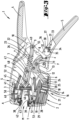
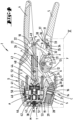
- a hand pliers 1 with a pliers head K having two pliers jaws 2, 3, and two pliers legs 4, 5.
- the pliers jaws 2 and 3 limit a pliers mouth M in a front side T of the hand pliers 1.
- the pliers jaw 2 which is referred to below as fixed, is directly and firmly connected to the pliers leg 4 via a cheek area 6.
- the stripping pliers 1 offer a bearing for a rotation axis 7 with a geometric axis x, around which the subsequently movable pliers jaw 3 is rotatably mounted.
- the mounting of the movable jaw 3 on the rotation axis 7 results in the region of a shoulder region of the movable jaw 3 extending in the direction of extension of the axis x in projection to the cheek region 6 of the fixed jaw 3.
- the geometric axis x preferably extends perpendicular to a broad side B of the pliers head K, to which broad side B is essentially perpendicular and, in the usual handling position, narrow sides S run on the top and bottom, the extension length a of which, viewed perpendicular to a broad side B, can correspond to one third or less, for example up to one tenth or less, of the extension length b of the broad side B viewed transversely to the axis x.
- the forceps jaw open position for example as shown in Figure 3 , may be stop-limited.
- the additional pliers leg 5 is pivotally mounted about a further geometric axis y, aligned parallel to the rotation axis 7 or its geometric axis x.
- the corresponding physical axis is also held in the cheek region 6 of the fixed pliers jaw 2 or the fixed pliers leg 4.
- a preferably angled control lever 8 is attached to the movable handle part 5, which with its free end, in the illustrated embodiment with a roller 9 preferably arranged in this area, rests against an extension arm 10 of the shoulder area of the movable pliers jaw 3, which extension arm is designed, for example, like a link.
- the control lever 8 is pivotally mounted on the movable pliers leg 5.
- the corresponding pivot axis z preferably runs parallel to the geometric rotation axis x.
- the cutting edge 12 is exposed in a cut-out area 13 of the cheek area 6 in the narrow side S which, during normal handling, preferably points downwards and is preferably used for cutting a cable to length, for example a cable to be stripped in a further step.
- the hand pliers 1 Facing the front side T, in particular the pliers mouth M, the hand pliers 1 have a stripping device A which is coupled to the movement of the pliers leg 5 and the control lever 8.
- the hand tool 1 has a crimping device C facing a narrow side S which is lower during normal handling, in which a cable 14 which has been stripped, for example, using the stripping device A, can be crimped with a pressed piece 16, in particular in the form of a wire end sleeve, in the area of the wires 15 which are subsequently exposed.
- the crimping device C can, as is also preferred, be provided between the area 13 for cutting a cable and the end face T, for which purpose a crimping opening 18 is left in the jaw wall 17 of the fixed jaw 2 forming the relevant narrow side S.
- a crimping jaw receptacle 19 is formed, in which a first crimping jaw 20 and a second crimping jaw 21 are jointly received and linearly guided.
- the displacement direction r of the crimping jaws 20 and 21 shown can, as further preferred, be substantially aligned in the same direction as an alignment and displacement direction of a pull rod 22 pivotably connected to the control lever 8 and cooperating with the stripping device A.
- a spring 23, here a cylinder compression spring, is preferably arranged, which the movable pliers leg 5 towards the Figure 3 shown basic position. In this basic position, the movable jaw 3 can also be held in a stop-limited basic position.
- the second crimping jaw 21, starting from the crimping opening 18, is arranged facing the end face T and can only be displaced indirectly linearly in the crimping jaw receptacle 19 during a crimping process.
- the first crimping jaw 20, on the other hand, can be displaced linearly directly in the crimping jaw receptacle 19 due to the action of a drive plunger 24, which drive plunger 24 is mounted on the first crimping jaw 20 as well as on the link 11 or on the cutting edge 12 so as to be pivotable about an axes 25 and 26 which are preferably aligned parallel to the axes x and/or y and/or z.
- the drive plunger 24 is designed like a link.
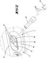
- the two crimping jaws 20 and 21 are provided with partially comb-like interlocking ribs 27, which are approximately triangular in shape when viewed in the direction of insertion of the cable 4 provided with the pressed part 16 into the crimping opening 18. This results in an unloaded basic position according to Figure 3 a crimping mouth 28 that is rectangular in plan, in particular square (compare for example Figure 2 ).
- the second crimping jaw 21, guided in the crimping jaw receptacle 19, is supported by a spring 29 in a base region of the crimping jaw receptacle 19.
- This spring can, as is also preferred, be an elastic, resilient polyurethane spring, which can be compressed accordingly when subjected to pressure, building up a restoring spring force.
- the pliers legs 4 and 5 When actuated, the pliers legs 4 and 5 preferably interact via a positive lock 30.
- the latter preferably acts both with respect to the crimping device C and with respect to the stripping device A, and optionally also with respect to the cutting device for cutting cables using the cutting edge 12.
- the forced lock 30 has a pawl 31 pivotally mounted on the movable pliers leg 5 and a ratchet projection 32 on the control lever 8 that interacts with the pawl 31 during the handling of the hand pliers 1.
- the pawl 31 is biased by a tension spring 33 into a basic orientation, for example according to Figure 3 charged.
- the pawl 31 which can be pivoted about an axis 34 aligned parallel to the axes described above, has a substantially radially projecting pawl finger 35 for ratcheting interaction with a plurality of locking steps 36, for example, as shown, three locking steps 36, of the ratchet projection 32.
- An actuating finger 37 can be provided offset in the circumferential direction with respect to the axis 34 relative to the pawl finger 35, by means of which the pawl 31 can be pivotally displaced manually into a position releasing the ratchet projection 32, if necessary.
- a stop limit can be provided in one and/or the other pivoting direction.
- the positive locking mechanism 30 during normal handling of the hand pliers 1, it is ensured that the crimping process or the stripping process, or if applicable, the cutting process, is completely completed, and a preferred end position of the respective tool is reached accordingly. Before this end position is reached, the interaction of the pawl 31 and the ratchet projection 32 prevents the movable pliers leg 5 from moving back toward the home position and thus, the concomitant movement of the movable pliers jaw 3 and/or the crimping jaws 20 and 21 back to the home position. In these intermediate handling positions, the pawl finger 35 cooperates with one of the locking steps 36 to provide a locking effect.
- a displacement path of the first crimping jaw 20 connected to the drive plunger 24 is always the same length, essentially independent of a thickness d of the compact 16 considered in the displacement direction r of the crimping jaws 20 and 21.
- the differential path resulting from the thickness d of the compact 16, over which the second crimping jaw 21 must be displaced linearly with the first crimping jaw 20 in the displacement direction r, is made possible by the arrangement of the spring 29.
- the corresponding support of the second crimping jaw 21 via the spring 29 allows a different linear displacement of the second crimping jaw 21 over the differential path, wherein according to a preferred embodiment, the spring force of the spring 29, in particular in the initial position, which is preferably limited by a stop with respect to the second crimping jaw 21, according to Figure 3 can be sufficiently high to absorb the pressing forces acting on the first crimping jaw 20 during a normal pressing process. A displacement of the second crimping jaw 21 against The restoring force of the spring 29 can thus only take place when the crimping is completed or alternatively simultaneously with the crimping.
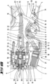
- the two jaws 2 and 3 each have an outer clamping jaw 38, 39 for clamping a cable 14 inserted into the jaws M for stripping a free end, see also Figures 9 to 10 .
- two inner cutting jaws 40, 41 are provided, each with cutting edges 42, 43 fixed in the end region facing the clamping jaws 38 and 39.
- the cutting edges 42 and 43 are arranged facing one another.
- the geometric axis of the pivot axis 44 extends in the operational arrangement of the cutting jaw pair preferably in parallel alignment to the rotation axis x of the movable pliers jaw 3.
- a spring 45 is arranged between the cutting jaws 40 and 41, which spring 45 loads the cutting jaws 40 and 41 into an open position spaced apart from one another.
- a stop slide 46 which can be locked in place in the direction of extension of the cutting jaw 41 is provided on the lower cutting jaw 41, i.e. on the cutting jaw 41 assigned to the fixed pliers jaw 2, for providing a stop for the free end of the cable 14 inserted into the pliers mouth M in order to define the length of the area to be stripped.
- the cutting jaws 40 and 41 are guided laterally in the respectively associated pliers jaw 2, 3, to enable a proper sliding displacement of the cutting jaws 40 and 41 in the direction of their longitudinal extent, i.e. starting from an initial position associated with the clamping jaws 38 and 39 in the direction of an end position spaced from the clamping jaws 38 and 39 and displaced in the direction of the rotation axis x and from this end position back into the initial position.
- the pull rod 22 is provided for this displacement of the cutting jaws 40, 41.
- the cutting jaws 40, 41 can be displaced from an initial position to an end position by compressing the handle parts 4, 5 against the force of the spring 23 acting on the pull rod 22.
- the pull rod 22 Associated with the pivot axis 44 of the pair of cutting jaws, the pull rod 22 has a substantially in the direction of the fixed jaw 2, furthermore substantially in the closing or opening direction of the cutting jaws 40 and 41. This is created by an overall hook-like design of the relevant end region of the pull rod 22.
- This sliding displacement of the pull rod 22 is made possible by a coupling with the control lever 8 held on the movable handle part 5, which control lever 8 engages in a bore 49 on the pull rod side with a pull axis 55 aligned parallel to the axis of rotation 7, which in the illustrated embodiment can also form the axis for the roller 9.
- Each cutting jaw 40, 41 is supported in the associated pliers jaw 2, 3 via a link part 50, 51, which link part 50, 51 can in turn be supported on a link fixed to the clamping jaw.
- the pliers jaw M is initially closed due to a corresponding pivoting displacement of the movable pliers jaw 3, superimposed on a closure of the pair of cutting jaws (compare Figures 9 and 10 ).
- the cutting edges 42 and 43 of the cutting jaws 40 and 41 cut into the insulation jacket of the cable 14, with a cutting depth that is preferably adjusted automatically depending on the cable thickness.
- the cantilever-side roller 9 leaves the supporting position for the cantilever 10 of the movable pliers jaw 3, which pivots back toward its open basic position, simultaneously opening the pliers jaw M and the pair of cutting jaws. This is due, among other things, to the restoring force of the spring 45 provided between the cutting jaws 40 and 41.
- the cable 14, stripped at the end, is exposed for removal from the hand-held pliers 1.
- the severed and pulled-off insulation section 54 is exposed for removal or, if necessary, falls automatically out of the pliers jaws M.
- the stripped end of the cable which may be fitted with a wire end sleeve, can then be crimped or pressed using the same hand tool 1.
- ⁇ b> ⁇ u>List of reference symbols ⁇ /u> ⁇ /b> 1 hand pliers 30 Compulsory closure 2 pliers jaw 31 pawl 3 pliers jaw 32 Ratchet projection 4 Forceps limbs 33 tension spring 5 Forceps limbs 34 axis 6 Cheek area 35 Jack fingers 7 axis of rotation 36 locking step 8 control lever 37 Actuating finger 9 role 38 clamping jaw 10 boom 39 clamping jaw 11 handlebar 40 Cutting jaw 12 Cutting edge 41 Cutting jaw 13 Area 42 Cutting edge 14 Cable 43 Cutting edge 15 vein 44 Swivel axis 16 Pressing 45 Feather 17 jaw wall 46 Stop slide 18 Crimp opening 47 recess 19 Crimping jaw holder 48 Entrance opening 20 first crimping jaw 49 drilling 21 second crimping jaw 50 Scenery part 22 drawbar 51 Scenery part 23 Feather 52 handlebar 24 Drive tappet 53 handlebar 25 axis 54
Landscapes
- Engineering & Computer Science (AREA)
- Mechanical Engineering (AREA)
- Manufacturing & Machinery (AREA)
- Manufacturing Of Electrical Connectors (AREA)
- Hand Tools For Fitting Together And Separating, Or Other Hand Tools (AREA)
- Gripping Jigs, Holding Jigs, And Positioning Jigs (AREA)
- Knives (AREA)
- Removal Of Insulation Or Armoring From Wires Or Cables (AREA)
- Processing Of Terminals (AREA)
Claims (5)
- Pince manuelle (1) conçue pour effectuer un sertissage, comprenant une branche de pince fixe et une branche de pince mobile (4, 5) ainsi qu'une première et une deuxième mâchoire de sertissage (20, 21), la première mâchoire de sertissage (20) étant sollicitée par un poussoir d'entraînement (24), caractérisée en ce que la première et la deuxième mâchoire de sertissage (20, 21) sont pourvues de nervures (27) s'engageant partiellement les unes dans les autres à la manière d'un peigne, qui sont de forme triangulaire en regardant dans la direction d'insertion d'un câble (4) muni d'une pièce sertie (16) dans une ouverture de sertissage (18), une bouche de sertissage (28) rectangulaire en plan étant obtenue dans une position de base non chargée, en ce que la deuxième mâchoire de sertissage (21) peut être déplacée en arrière dans un logement de mâchoire de sertissage (19) de la pince manuelle (1) contre la force d'un ressort et en ce que la première et la deuxième mâchoires de sertissage (20, 21) sont disposées dans un guidage linéaire commun.
- Pince manuelle (1) selon la revendication 1, caractérisée par une tête de pince qui est formée par des mâchoires de pince (2, 3) pouvant pivoter l'une par rapport à l'autre, qui coopèrent pour le dénudage, la tête de pince présentant un côté large (B), un premier et un deuxième côté étroit (S) s'étendant, dans une position de manipulation usuelle, sur le côté supérieur et le côté inférieur, essentiellement perpendiculairement au côté large, et un côté frontal (T), un axe de pivotement (x) des mâchoires de pince (2, 3) s'étendant en outre perpendiculairement à une extension du côté large (B) et une ouverture de sertissage (18) formée par les mâchoires de sertissage (20, 21) débouchant dans le premier ou le deuxième côté étroit (S).
- Pince manuelle selon la revendication 1, caractérisée en ce que la pince manuelle (1) est en outre conçue comme une pince à dénuder.
- Pince manuelle selon l'une des revendications précédentes, caractérisée en ce que les branches de la pince (4, 5) coopèrent par l'intermédiaire d'un blocage forcé (30).
- Pince manuelle selon la revendication 4, caractérisée en ce que le blocage forcé (30) agit entre un levier de commande (8) et la branche mobile (5) de la pince
Applications Claiming Priority (2)
| Application Number | Priority Date | Filing Date | Title |
|---|---|---|---|
| DE102020121823.0A DE102020121823A1 (de) | 2020-08-20 | 2020-08-20 | Zur Durchführung einer Vercrimpung ausgebildete Handzange sowie Handzange mit einem Zangenkopf |
| PCT/EP2021/072939 WO2022038186A2 (fr) | 2020-08-20 | 2021-08-18 | Pince manuelle conçue pour réaliser un sertissage et pince manuelle pourvue d'une tête de pince |
Publications (2)
| Publication Number | Publication Date |
|---|---|
| EP4200946A2 EP4200946A2 (fr) | 2023-06-28 |
| EP4200946B1 true EP4200946B1 (fr) | 2025-04-30 |
Family
ID=77655536
Family Applications (1)
| Application Number | Title | Priority Date | Filing Date |
|---|---|---|---|
| EP21766141.2A Active EP4200946B1 (fr) | 2020-08-20 | 2021-08-18 | Pince manuelle conçue pour réaliser un sertissage et pince manuelle pourvue d'une tête de pince |
Country Status (12)
| Country | Link |
|---|---|
| EP (1) | EP4200946B1 (fr) |
| JP (1) | JP7752645B2 (fr) |
| KR (1) | KR20230052936A (fr) |
| CN (1) | CN116097535A (fr) |
| AU (1) | AU2021327144B2 (fr) |
| CA (1) | CA3173002A1 (fr) |
| DE (1) | DE102020121823A1 (fr) |
| ES (1) | ES3032890T3 (fr) |
| MX (1) | MX428907B (fr) |
| PL (1) | PL4200946T3 (fr) |
| TW (1) | TWI891884B (fr) |
| WO (1) | WO2022038186A2 (fr) |
Families Citing this family (2)
| Publication number | Priority date | Publication date | Assignee | Title |
|---|---|---|---|---|
| EP4730574A1 (fr) * | 2024-10-15 | 2026-04-22 | Kauw Yehi Industrial Co., Ltd. | Structure de pince à sertissage par encliquetage |
| CN119651306B (zh) * | 2024-12-23 | 2025-10-21 | 中铁二十五局集团电务工程有限公司 | 城市轨道施工用电缆压接设备及使用方法 |
Family Cites Families (21)
| Publication number | Priority date | Publication date | Assignee | Title |
|---|---|---|---|---|
| US3531971A (en) * | 1965-07-26 | 1970-10-06 | Itt | Cable insulation piercing crimp tool,terminal,and method of forming |
| JPS6153881U (fr) * | 1984-09-13 | 1986-04-11 | ||
| JPS61290678A (ja) * | 1985-06-19 | 1986-12-20 | ヒロセ電機株式会社 | 手動結線工具 |
| US5042286A (en) * | 1988-05-09 | 1991-08-27 | C.A. Weidmuller Gmbh & Co. | Manually operated pliers-type tool |
| US4912958A (en) * | 1989-04-19 | 1990-04-03 | Electro-Appliance Co., Inc. | Hand tool for pressing wire connectors |
| DE4136302C1 (fr) | 1991-11-04 | 1993-03-11 | Weidmueller Interface Gmbh & Co, 4930 Detmold, De | |
| JPH0677191U (ja) * | 1992-07-21 | 1994-10-28 | 昭三 井手口 | モジュラープラグの万能圧接工具 |
| FR2704169B1 (fr) * | 1993-04-22 | 1995-07-07 | Legrand Sa | Outil à main pour la coupe d'un conducteur électrique isolé, son dénudage et le sertissage d'un embout de câblage sur son extrémité dénudée. |
| US6279431B1 (en) * | 1999-06-15 | 2001-08-28 | Brett P. Seber | Self-adjusting pliers |
| DE102004003462B3 (de) | 2004-01-22 | 2005-08-11 | Rennsteig Werkzeuge Gmbh | Abisolierzange mit automatischer Anpassung an verschiedene Leiterquerschnitte |
| US7073245B2 (en) * | 2004-05-14 | 2006-07-11 | Fluke Corporation | Multiple-wire termination tool with translatable jack and cutting blade precision alignment carrier |
| EP2056416B1 (fr) * | 2007-11-02 | 2016-08-17 | Weidmüller Interface GmbH & Co. KG | Pince à dénuder |
| TW201110484A (en) * | 2009-09-03 | 2011-03-16 | Toolmartt Entpr Co Ltd | Line pressing device for two in one communication connector |
| EP2672580B1 (fr) * | 2012-06-05 | 2017-02-01 | Wezag GmbH Werkzeugfabrik | Tête de pince de sertissage |
| DE202014100359U1 (de) * | 2014-01-28 | 2014-03-05 | CIMCO-Werkzeugfabrik Carl Jul. Müller GmbH & Co. KG | Presswerkzeug |
| EP3208044A1 (fr) * | 2016-02-18 | 2017-08-23 | Wezag GmbH Werkzeugfabrik | Pince comprenant un systeme de levier a genouillere |
| EP3396796B1 (fr) * | 2017-04-25 | 2021-07-21 | WEZAG GmbH & Co. KG | Outil de compression, de sertissage ou de découpe et module d'outils |
| DE102017128227A1 (de) * | 2017-11-29 | 2019-05-29 | Rennsteig Werkzeuge Gmbh | Klemmbacken und Schneiden für eine Abisolierzange, sowie Abisolierzange |
| DE102017128584A1 (de) * | 2017-12-01 | 2019-06-06 | Rennsteig Werkzeuge Gmbh | Presszange |
| DE102018101159B4 (de) * | 2017-12-01 | 2026-07-30 | Rennsteig Werkzeuge Gmbh | Presszange mit zwei Zangenbacken |
| US20190312397A1 (en) * | 2018-04-09 | 2019-10-10 | Robert Bosch Gmbh | Inline Crimper with Reconfigurable Components |
-
2020
- 2020-08-20 DE DE102020121823.0A patent/DE102020121823A1/de not_active Withdrawn
-
2021
- 2021-08-18 AU AU2021327144A patent/AU2021327144B2/en active Active
- 2021-08-18 CN CN202180056737.3A patent/CN116097535A/zh active Pending
- 2021-08-18 ES ES21766141T patent/ES3032890T3/es active Active
- 2021-08-18 WO PCT/EP2021/072939 patent/WO2022038186A2/fr not_active Ceased
- 2021-08-18 CA CA3173002A patent/CA3173002A1/fr active Pending
- 2021-08-18 KR KR1020237009272A patent/KR20230052936A/ko active Pending
- 2021-08-18 JP JP2022580733A patent/JP7752645B2/ja active Active
- 2021-08-18 EP EP21766141.2A patent/EP4200946B1/fr active Active
- 2021-08-18 PL PL21766141.2T patent/PL4200946T3/pl unknown
- 2021-08-18 MX MX2023001992A patent/MX428907B/es unknown
- 2021-08-19 TW TW110130722A patent/TWI891884B/zh active
Also Published As
| Publication number | Publication date |
|---|---|
| KR20230052936A (ko) | 2023-04-20 |
| DE102020121823A1 (de) | 2022-02-24 |
| WO2022038186A3 (fr) | 2022-05-05 |
| CN116097535A (zh) | 2023-05-09 |
| MX2023001992A (es) | 2023-02-27 |
| TW202212064A (zh) | 2022-04-01 |
| EP4200946A2 (fr) | 2023-06-28 |
| WO2022038186A2 (fr) | 2022-02-24 |
| AU2021327144B2 (en) | 2026-08-06 |
| ES3032890T3 (en) | 2025-07-28 |
| AU2021327144A1 (en) | 2023-01-19 |
| JP2023543650A (ja) | 2023-10-18 |
| PL4200946T3 (pl) | 2025-08-04 |
| CA3173002A1 (fr) | 2022-02-04 |
| MX428907B (es) | 2025-11-13 |
| JP7752645B2 (ja) | 2025-10-10 |
| TWI891884B (zh) | 2025-08-01 |
Similar Documents
| Publication | Publication Date | Title |
|---|---|---|
| EP4311627B1 (fr) | Mâchoires de pressage ainsi que pince de pressage avec deux mâchoires de serrage | |
| EP2873122B1 (fr) | Outil de sertissage pour douille d'extrêmité de conducteur | |
| EP2107650B1 (fr) | Pince de serrage dotée d'un positionneur | |
| EP3012923B1 (fr) | Pince de pression | |
| EP3718186B1 (fr) | Pince a dénuder | |
| EP0540880B1 (fr) | Pince de sertissage pour extrémités de fils | |
| EP2685573B1 (fr) | Outil de sertissage pour contacts tournés | |
| EP2672580B1 (fr) | Tête de pince de sertissage | |
| EP3718184B1 (fr) | Mâchoires de serrage pour une pince à dénuder et pince à dénuder | |
| DE2402187A1 (de) | Geraet zum abstreifen der verkleidung von bezogenen leitungen und dgl. | |
| DE102018121971A1 (de) | Presswerkzeug | |
| EP0309871B1 (fr) | Pince à main pour dénuder les extrémités de conducteurs | |
| DE3241530A1 (de) | Abisolierzange | |
| EP3054541B1 (fr) | Pince à dénuder | |
| WO2019105707A1 (fr) | Pince à dénuder | |
| DE102019106353A1 (de) | Leiteranschlussklemme mit einem Betätigungselement mit angepasster Druckfläche | |
| EP1922787B1 (fr) | Outil de double sertissage | |
| DE19607949C1 (de) | Abisoliervorrichtung | |
| EP4200946A2 (fr) | Pince manuelle conçue pour réaliser un sertissage et pince manuelle pourvue d'une tête de pince | |
| DE20310377U1 (de) | Zange mit einer Abisolierstation | |
| DE2113107A1 (de) | Vorrichtung zum Durchschneiden und teilweisen Abisolieren elektrischer Draehte oder Kabel | |
| DE2521378C3 (de) | Zange zum Verpressen von Kabelverbindern (Crimp-Werkzeug) | |
| EP4219075A1 (fr) | Outil de presse manuel | |
| DE1181766B (de) | Zange zum Kerben von Werkstuecken | |
| EP0924817B1 (fr) | Pince à sertir, mors pour cette pince, et procédé de manipulation de celle-ci |
Legal Events
| Date | Code | Title | Description |
|---|---|---|---|
| STAA | Information on the status of an ep patent application or granted ep patent |
Free format text: STATUS: UNKNOWN |
|
| STAA | Information on the status of an ep patent application or granted ep patent |
Free format text: STATUS: THE INTERNATIONAL PUBLICATION HAS BEEN MADE |
|
| PUAI | Public reference made under article 153(3) epc to a published international application that has entered the european phase |
Free format text: ORIGINAL CODE: 0009012 |
|
| STAA | Information on the status of an ep patent application or granted ep patent |
Free format text: STATUS: REQUEST FOR EXAMINATION WAS MADE |
|
| 17P | Request for examination filed |
Effective date: 20230309 |
|
| AK | Designated contracting states |
Kind code of ref document: A2 Designated state(s): AL AT BE BG CH CY CZ DE DK EE ES FI FR GB GR HR HU IE IS IT LI LT LU LV MC MK MT NL NO PL PT RO RS SE SI SK SM TR |
|
| REG | Reference to a national code |
Ref country code: HK Ref legal event code: DE Ref document number: 40089153 Country of ref document: HK |
|
| DAV | Request for validation of the european patent (deleted) | ||
| DAX | Request for extension of the european patent (deleted) | ||
| GRAP | Despatch of communication of intention to grant a patent |
Free format text: ORIGINAL CODE: EPIDOSNIGR1 |
|
| STAA | Information on the status of an ep patent application or granted ep patent |
Free format text: STATUS: GRANT OF PATENT IS INTENDED |
|
| INTG | Intention to grant announced |
Effective date: 20241219 |
|
| GRAS | Grant fee paid |
Free format text: ORIGINAL CODE: EPIDOSNIGR3 |
|
| GRAA | (expected) grant |
Free format text: ORIGINAL CODE: 0009210 |
|
| STAA | Information on the status of an ep patent application or granted ep patent |
Free format text: STATUS: THE PATENT HAS BEEN GRANTED |
|
| AK | Designated contracting states |
Kind code of ref document: B1 Designated state(s): AL AT BE BG CH CY CZ DE DK EE ES FI FR GB GR HR HU IE IS IT LI LT LU LV MC MK MT NL NO PL PT RO RS SE SI SK SM TR |
|
| P01 | Opt-out of the competence of the unified patent court (upc) registered |
Free format text: CASE NUMBER: APP_14265/2025 Effective date: 20250324 |
|
| REG | Reference to a national code |
Ref country code: CH Ref legal event code: EP Ref country code: GB Ref legal event code: FG4D Free format text: NOT ENGLISH |
|
| REG | Reference to a national code |
Ref country code: DE Ref legal event code: R096 Ref document number: 502021007360 Country of ref document: DE |
|
| REG | Reference to a national code |
Ref country code: IE Ref legal event code: FG4D Free format text: LANGUAGE OF EP DOCUMENT: GERMAN |
|
| REG | Reference to a national code |
Ref country code: SE Ref legal event code: TRGR |
|
| REG | Reference to a national code |
Ref country code: ES Ref legal event code: FG2A Ref document number: 3032890 Country of ref document: ES Kind code of ref document: T3 Effective date: 20250728 |
|
| PG25 | Lapsed in a contracting state [announced via postgrant information from national office to epo] |
Ref country code: PT Free format text: LAPSE BECAUSE OF FAILURE TO SUBMIT A TRANSLATION OF THE DESCRIPTION OR TO PAY THE FEE WITHIN THE PRESCRIBED TIME-LIMIT Effective date: 20250901 Ref country code: FI Free format text: LAPSE BECAUSE OF FAILURE TO SUBMIT A TRANSLATION OF THE DESCRIPTION OR TO PAY THE FEE WITHIN THE PRESCRIBED TIME-LIMIT Effective date: 20250430 |
|
| PGFP | Annual fee paid to national office [announced via postgrant information from national office to epo] |
Ref country code: ES Payment date: 20250911 Year of fee payment: 5 |
|
| PGFP | Annual fee paid to national office [announced via postgrant information from national office to epo] |
Ref country code: DE Payment date: 20250821 Year of fee payment: 5 |
|
| REG | Reference to a national code |
Ref country code: LT Ref legal event code: MG9D |
|
| PG25 | Lapsed in a contracting state [announced via postgrant information from national office to epo] |
Ref country code: NO Free format text: LAPSE BECAUSE OF FAILURE TO SUBMIT A TRANSLATION OF THE DESCRIPTION OR TO PAY THE FEE WITHIN THE PRESCRIBED TIME-LIMIT Effective date: 20250730 Ref country code: GR Free format text: LAPSE BECAUSE OF FAILURE TO SUBMIT A TRANSLATION OF THE DESCRIPTION OR TO PAY THE FEE WITHIN THE PRESCRIBED TIME-LIMIT Effective date: 20250731 |
|
| PG25 | Lapsed in a contracting state [announced via postgrant information from national office to epo] |
Ref country code: NL Free format text: LAPSE BECAUSE OF FAILURE TO SUBMIT A TRANSLATION OF THE DESCRIPTION OR TO PAY THE FEE WITHIN THE PRESCRIBED TIME-LIMIT Effective date: 20250430 |
|
| PGFP | Annual fee paid to national office [announced via postgrant information from national office to epo] |
Ref country code: IT Payment date: 20250827 Year of fee payment: 5 Ref country code: PL Payment date: 20250721 Year of fee payment: 5 |
|
| PG25 | Lapsed in a contracting state [announced via postgrant information from national office to epo] |
Ref country code: BG Free format text: LAPSE BECAUSE OF FAILURE TO SUBMIT A TRANSLATION OF THE DESCRIPTION OR TO PAY THE FEE WITHIN THE PRESCRIBED TIME-LIMIT Effective date: 20250430 |
|
| PGFP | Annual fee paid to national office [announced via postgrant information from national office to epo] |
Ref country code: GB Payment date: 20250819 Year of fee payment: 5 |
|
| PG25 | Lapsed in a contracting state [announced via postgrant information from national office to epo] |
Ref country code: HR Free format text: LAPSE BECAUSE OF FAILURE TO SUBMIT A TRANSLATION OF THE DESCRIPTION OR TO PAY THE FEE WITHIN THE PRESCRIBED TIME-LIMIT Effective date: 20250430 |
|
| PGFP | Annual fee paid to national office [announced via postgrant information from national office to epo] |
Ref country code: FR Payment date: 20250819 Year of fee payment: 5 Ref country code: AT Payment date: 20251020 Year of fee payment: 5 |
|
| PGFP | Annual fee paid to national office [announced via postgrant information from national office to epo] |
Ref country code: SE Payment date: 20250819 Year of fee payment: 5 |
|
| PG25 | Lapsed in a contracting state [announced via postgrant information from national office to epo] |
Ref country code: RS Free format text: LAPSE BECAUSE OF FAILURE TO SUBMIT A TRANSLATION OF THE DESCRIPTION OR TO PAY THE FEE WITHIN THE PRESCRIBED TIME-LIMIT Effective date: 20250731 |
|
| PG25 | Lapsed in a contracting state [announced via postgrant information from national office to epo] |
Ref country code: IS Free format text: LAPSE BECAUSE OF FAILURE TO SUBMIT A TRANSLATION OF THE DESCRIPTION OR TO PAY THE FEE WITHIN THE PRESCRIBED TIME-LIMIT Effective date: 20250830 |
|
| PG25 | Lapsed in a contracting state [announced via postgrant information from national office to epo] |
Ref country code: LV Free format text: LAPSE BECAUSE OF FAILURE TO SUBMIT A TRANSLATION OF THE DESCRIPTION OR TO PAY THE FEE WITHIN THE PRESCRIBED TIME-LIMIT Effective date: 20250430 |
|
| PG25 | Lapsed in a contracting state [announced via postgrant information from national office to epo] |
Ref country code: SM Free format text: LAPSE BECAUSE OF FAILURE TO SUBMIT A TRANSLATION OF THE DESCRIPTION OR TO PAY THE FEE WITHIN THE PRESCRIBED TIME-LIMIT Effective date: 20250430 Ref country code: DK Free format text: LAPSE BECAUSE OF FAILURE TO SUBMIT A TRANSLATION OF THE DESCRIPTION OR TO PAY THE FEE WITHIN THE PRESCRIBED TIME-LIMIT Effective date: 20250430 |
|
| PG25 | Lapsed in a contracting state [announced via postgrant information from national office to epo] |
Ref country code: CZ Free format text: LAPSE BECAUSE OF FAILURE TO SUBMIT A TRANSLATION OF THE DESCRIPTION OR TO PAY THE FEE WITHIN THE PRESCRIBED TIME-LIMIT Effective date: 20250430 |
|
| PG25 | Lapsed in a contracting state [announced via postgrant information from national office to epo] |
Ref country code: EE Free format text: LAPSE BECAUSE OF FAILURE TO SUBMIT A TRANSLATION OF THE DESCRIPTION OR TO PAY THE FEE WITHIN THE PRESCRIBED TIME-LIMIT Effective date: 20250430 |
|
| PG25 | Lapsed in a contracting state [announced via postgrant information from national office to epo] |
Ref country code: SK Free format text: LAPSE BECAUSE OF FAILURE TO SUBMIT A TRANSLATION OF THE DESCRIPTION OR TO PAY THE FEE WITHIN THE PRESCRIBED TIME-LIMIT Effective date: 20250430 |
|
| REG | Reference to a national code |
Ref country code: DE Ref legal event code: R097 Ref document number: 502021007360 Country of ref document: DE |
|
| PG25 | Lapsed in a contracting state [announced via postgrant information from national office to epo] |
Ref country code: RO Free format text: LAPSE BECAUSE OF FAILURE TO SUBMIT A TRANSLATION OF THE DESCRIPTION OR TO PAY THE FEE WITHIN THE PRESCRIBED TIME-LIMIT Effective date: 20250430 |
|
| PLBE | No opposition filed within time limit |
Free format text: ORIGINAL CODE: 0009261 |
|
| STAA | Information on the status of an ep patent application or granted ep patent |
Free format text: STATUS: NO OPPOSITION FILED WITHIN TIME LIMIT |
|
| REG | Reference to a national code |
Ref country code: CH Ref legal event code: L10 Free format text: ST27 STATUS EVENT CODE: U-0-0-L10-L00 (AS PROVIDED BY THE NATIONAL OFFICE) Effective date: 20260311 |
|
| REG | Reference to a national code |
Ref country code: CH Ref legal event code: H13 Free format text: ST27 STATUS EVENT CODE: U-0-0-H10-H13 (AS PROVIDED BY THE NATIONAL OFFICE) Effective date: 20260324 |
|
| PG25 | Lapsed in a contracting state [announced via postgrant information from national office to epo] |
Ref country code: MC Free format text: LAPSE BECAUSE OF FAILURE TO SUBMIT A TRANSLATION OF THE DESCRIPTION OR TO PAY THE FEE WITHIN THE PRESCRIBED TIME-LIMIT Effective date: 20250430 |
|
| 26N | No opposition filed |
Effective date: 20260202 |
|
| PG25 | Lapsed in a contracting state [announced via postgrant information from national office to epo] |
Ref country code: LU Free format text: LAPSE BECAUSE OF NON-PAYMENT OF DUE FEES Effective date: 20250818 |
|
| PG25 | Lapsed in a contracting state [announced via postgrant information from national office to epo] |
Ref country code: CH Free format text: LAPSE BECAUSE OF NON-PAYMENT OF DUE FEES Effective date: 20250831 |
|
| REG | Reference to a national code |
Ref country code: BE Ref legal event code: MM Effective date: 20250831 |
|
| PG25 | Lapsed in a contracting state [announced via postgrant information from national office to epo] |
Ref country code: LT Free format text: LAPSE BECAUSE OF FAILURE TO SUBMIT A TRANSLATION OF THE DESCRIPTION OR TO PAY THE FEE WITHIN THE PRESCRIBED TIME-LIMIT Effective date: 20250430 |
|
| PG25 | Lapsed in a contracting state [announced via postgrant information from national office to epo] |
Ref country code: IE Free format text: LAPSE BECAUSE OF NON-PAYMENT OF DUE FEES Effective date: 20250818 Ref country code: BE Free format text: LAPSE BECAUSE OF NON-PAYMENT OF DUE FEES Effective date: 20250831 |