EP2673782B1 - Dispositif de piegeage de gaz inflammables produits par radiolyse ou thermolyse dans une enceinte de confinement - Google Patents
Dispositif de piegeage de gaz inflammables produits par radiolyse ou thermolyse dans une enceinte de confinement Download PDFInfo
- Publication number
- EP2673782B1 EP2673782B1 EP12702853.8A EP12702853A EP2673782B1 EP 2673782 B1 EP2673782 B1 EP 2673782B1 EP 12702853 A EP12702853 A EP 12702853A EP 2673782 B1 EP2673782 B1 EP 2673782B1
- Authority
- EP
- European Patent Office
- Prior art keywords
- gases
- filter
- trapping
- casing
- active means
- Prior art date
- Legal status (The legal status is an assumption and is not a legal conclusion. Google has not performed a legal analysis and makes no representation as to the accuracy of the status listed.)
- Active
Links
Images


Classifications
-
- B—PERFORMING OPERATIONS; TRANSPORTING
- B01—PHYSICAL OR CHEMICAL PROCESSES OR APPARATUS IN GENERAL
- B01D—SEPARATION
- B01D53/00—Separation of gases or vapours; Recovering vapours of volatile solvents from gases; Chemical or biological purification of waste gases, e.g. engine exhaust gases, smoke, fumes, flue gases, aerosols
- B01D53/22—Separation of gases or vapours; Recovering vapours of volatile solvents from gases; Chemical or biological purification of waste gases, e.g. engine exhaust gases, smoke, fumes, flue gases, aerosols by diffusion
-
- G—PHYSICS
- G21—NUCLEAR PHYSICS; NUCLEAR ENGINEERING
- G21C—NUCLEAR REACTORS
- G21C19/00—Arrangements for treating, for handling, or for facilitating the handling of, fuel or other materials which are used within the reactor, e.g. within its pressure vessel
- G21C19/28—Arrangements for introducing fluent material into the reactor core; Arrangements for removing fluent material from the reactor core
- G21C19/30—Arrangements for introducing fluent material into the reactor core; Arrangements for removing fluent material from the reactor core with continuous purification of circulating fluent material, e.g. by extraction of fission products deterioration or corrosion products, impurities, e.g. by cold traps
- G21C19/317—Recombination devices for radiolytic dissociation products
-
- B—PERFORMING OPERATIONS; TRANSPORTING
- B01—PHYSICAL OR CHEMICAL PROCESSES OR APPARATUS IN GENERAL
- B01D—SEPARATION
- B01D53/00—Separation of gases or vapours; Recovering vapours of volatile solvents from gases; Chemical or biological purification of waste gases, e.g. engine exhaust gases, smoke, fumes, flue gases, aerosols
- B01D53/02—Separation of gases or vapours; Recovering vapours of volatile solvents from gases; Chemical or biological purification of waste gases, e.g. engine exhaust gases, smoke, fumes, flue gases, aerosols by adsorption, e.g. preparative gas chromatography
- B01D53/04—Separation of gases or vapours; Recovering vapours of volatile solvents from gases; Chemical or biological purification of waste gases, e.g. engine exhaust gases, smoke, fumes, flue gases, aerosols by adsorption, e.g. preparative gas chromatography with stationary adsorbents
- B01D53/0407—Constructional details of adsorbing systems
-
- B—PERFORMING OPERATIONS; TRANSPORTING
- B01—PHYSICAL OR CHEMICAL PROCESSES OR APPARATUS IN GENERAL
- B01D—SEPARATION
- B01D53/00—Separation of gases or vapours; Recovering vapours of volatile solvents from gases; Chemical or biological purification of waste gases, e.g. engine exhaust gases, smoke, fumes, flue gases, aerosols
-
- B—PERFORMING OPERATIONS; TRANSPORTING
- B01—PHYSICAL OR CHEMICAL PROCESSES OR APPARATUS IN GENERAL
- B01D—SEPARATION
- B01D53/00—Separation of gases or vapours; Recovering vapours of volatile solvents from gases; Chemical or biological purification of waste gases, e.g. engine exhaust gases, smoke, fumes, flue gases, aerosols
- B01D53/22—Separation of gases or vapours; Recovering vapours of volatile solvents from gases; Chemical or biological purification of waste gases, e.g. engine exhaust gases, smoke, fumes, flue gases, aerosols by diffusion
- B01D53/229—Integrated processes (Diffusion and at least one other process, e.g. adsorption, absorption)
-
- B—PERFORMING OPERATIONS; TRANSPORTING
- B01—PHYSICAL OR CHEMICAL PROCESSES OR APPARATUS IN GENERAL
- B01D—SEPARATION
- B01D53/00—Separation of gases or vapours; Recovering vapours of volatile solvents from gases; Chemical or biological purification of waste gases, e.g. engine exhaust gases, smoke, fumes, flue gases, aerosols
- B01D53/34—Chemical or biological purification of waste gases
- B01D53/46—Removing components of defined structure
-
- B—PERFORMING OPERATIONS; TRANSPORTING
- B01—PHYSICAL OR CHEMICAL PROCESSES OR APPARATUS IN GENERAL
- B01J—CHEMICAL OR PHYSICAL PROCESSES, e.g. CATALYSIS OR COLLOID CHEMISTRY; THEIR RELEVANT APPARATUS
- B01J20/00—Solid sorbent compositions or filter aid compositions; Sorbents for chromatography; Processes for preparing, regenerating or reactivating thereof
- B01J20/02—Solid sorbent compositions or filter aid compositions; Sorbents for chromatography; Processes for preparing, regenerating or reactivating thereof comprising inorganic material
-
- B—PERFORMING OPERATIONS; TRANSPORTING
- B01—PHYSICAL OR CHEMICAL PROCESSES OR APPARATUS IN GENERAL
- B01J—CHEMICAL OR PHYSICAL PROCESSES, e.g. CATALYSIS OR COLLOID CHEMISTRY; THEIR RELEVANT APPARATUS
- B01J20/00—Solid sorbent compositions or filter aid compositions; Sorbents for chromatography; Processes for preparing, regenerating or reactivating thereof
- B01J20/02—Solid sorbent compositions or filter aid compositions; Sorbents for chromatography; Processes for preparing, regenerating or reactivating thereof comprising inorganic material
- B01J20/0203—Solid sorbent compositions or filter aid compositions; Sorbents for chromatography; Processes for preparing, regenerating or reactivating thereof comprising inorganic material comprising compounds of metals not provided for in B01J20/04
- B01J20/0274—Solid sorbent compositions or filter aid compositions; Sorbents for chromatography; Processes for preparing, regenerating or reactivating thereof comprising inorganic material comprising compounds of metals not provided for in B01J20/04 characterised by the type of anion
- B01J20/0277—Carbonates of compounds other than those provided for in B01J20/043
-
- B—PERFORMING OPERATIONS; TRANSPORTING
- B01—PHYSICAL OR CHEMICAL PROCESSES OR APPARATUS IN GENERAL
- B01J—CHEMICAL OR PHYSICAL PROCESSES, e.g. CATALYSIS OR COLLOID CHEMISTRY; THEIR RELEVANT APPARATUS
- B01J20/00—Solid sorbent compositions or filter aid compositions; Sorbents for chromatography; Processes for preparing, regenerating or reactivating thereof
- B01J20/02—Solid sorbent compositions or filter aid compositions; Sorbents for chromatography; Processes for preparing, regenerating or reactivating thereof comprising inorganic material
- B01J20/06—Solid sorbent compositions or filter aid compositions; Sorbents for chromatography; Processes for preparing, regenerating or reactivating thereof comprising inorganic material comprising oxides or hydroxides of metals not provided for in group B01J20/04
-
- B—PERFORMING OPERATIONS; TRANSPORTING
- B01—PHYSICAL OR CHEMICAL PROCESSES OR APPARATUS IN GENERAL
- B01J—CHEMICAL OR PHYSICAL PROCESSES, e.g. CATALYSIS OR COLLOID CHEMISTRY; THEIR RELEVANT APPARATUS
- B01J20/00—Solid sorbent compositions or filter aid compositions; Sorbents for chromatography; Processes for preparing, regenerating or reactivating thereof
- B01J20/02—Solid sorbent compositions or filter aid compositions; Sorbents for chromatography; Processes for preparing, regenerating or reactivating thereof comprising inorganic material
- B01J20/10—Solid sorbent compositions or filter aid compositions; Sorbents for chromatography; Processes for preparing, regenerating or reactivating thereof comprising inorganic material comprising silica or silicate
- B01J20/103—Solid sorbent compositions or filter aid compositions; Sorbents for chromatography; Processes for preparing, regenerating or reactivating thereof comprising inorganic material comprising silica or silicate comprising silica
-
- C—CHEMISTRY; METALLURGY
- C01—INORGANIC CHEMISTRY
- C01B—NON-METALLIC ELEMENTS; COMPOUNDS THEREOF; METALLOIDS OR COMPOUNDS THEREOF NOT COVERED BY SUBCLASS C01C
- C01B3/00—Hydrogen; Gaseous mixtures containing hydrogen; Separation of hydrogen from mixtures containing it; Purification of hydrogen; Reversible storage of hydrogen
-
- C—CHEMISTRY; METALLURGY
- C01—INORGANIC CHEMISTRY
- C01B—NON-METALLIC ELEMENTS; COMPOUNDS THEREOF; METALLOIDS OR COMPOUNDS THEREOF NOT COVERED BY SUBCLASS C01C
- C01B3/00—Hydrogen; Gaseous mixtures containing hydrogen; Separation of hydrogen from mixtures containing it; Purification of hydrogen; Reversible storage of hydrogen
- C01B3/0005—Reversible storage of hydrogen, e.g. by hydrogen getters or electrodes
- C01B3/001—Reversible storage of hydrogen, e.g. by hydrogen getters or electrodes characterised by the uptaking media; Treatment thereof
-
- C—CHEMISTRY; METALLURGY
- C01—INORGANIC CHEMISTRY
- C01B—NON-METALLIC ELEMENTS; COMPOUNDS THEREOF; METALLOIDS OR COMPOUNDS THEREOF NOT COVERED BY SUBCLASS C01C
- C01B3/00—Hydrogen; Gaseous mixtures containing hydrogen; Separation of hydrogen from mixtures containing it; Purification of hydrogen; Reversible storage of hydrogen
- C01B3/0005—Reversible storage of hydrogen, e.g. by hydrogen getters or electrodes
- C01B3/001—Reversible storage of hydrogen, e.g. by hydrogen getters or electrodes characterised by the uptaking media; Treatment thereof
- C01B3/0018—Inorganic elements or compounds, e.g. oxides, nitrides, borohydrides or zeolites; Solutions thereof
- C01B3/0026—Metals or metal hydrides
-
- C—CHEMISTRY; METALLURGY
- C01—INORGANIC CHEMISTRY
- C01B—NON-METALLIC ELEMENTS; COMPOUNDS THEREOF; METALLOIDS OR COMPOUNDS THEREOF NOT COVERED BY SUBCLASS C01C
- C01B3/00—Hydrogen; Gaseous mixtures containing hydrogen; Separation of hydrogen from mixtures containing it; Purification of hydrogen; Reversible storage of hydrogen
- C01B3/0005—Reversible storage of hydrogen, e.g. by hydrogen getters or electrodes
- C01B3/001—Reversible storage of hydrogen, e.g. by hydrogen getters or electrodes characterised by the uptaking media; Treatment thereof
- C01B3/0018—Inorganic elements or compounds, e.g. oxides, nitrides, borohydrides or zeolites; Solutions thereof
- C01B3/0031—Intermetallic compounds; Metal alloys
-
- C—CHEMISTRY; METALLURGY
- C01—INORGANIC CHEMISTRY
- C01B—NON-METALLIC ELEMENTS; COMPOUNDS THEREOF; METALLOIDS OR COMPOUNDS THEREOF NOT COVERED BY SUBCLASS C01C
- C01B3/00—Hydrogen; Gaseous mixtures containing hydrogen; Separation of hydrogen from mixtures containing it; Purification of hydrogen; Reversible storage of hydrogen
- C01B3/50—Separation of hydrogen or hydrogen-containing gases from gaseous mixtures, e.g. purification
- C01B3/501—Separation of hydrogen or hydrogen-containing gases from gaseous mixtures, e.g. purification by diffusion
- C01B3/503—Separation of hydrogen or hydrogen-containing gases from gaseous mixtures, e.g. purification by diffusion characterised by membranes
-
- C—CHEMISTRY; METALLURGY
- C01—INORGANIC CHEMISTRY
- C01B—NON-METALLIC ELEMENTS; COMPOUNDS THEREOF; METALLOIDS OR COMPOUNDS THEREOF NOT COVERED BY SUBCLASS C01C
- C01B3/00—Hydrogen; Gaseous mixtures containing hydrogen; Separation of hydrogen from mixtures containing it; Purification of hydrogen; Reversible storage of hydrogen
- C01B3/50—Separation of hydrogen or hydrogen-containing gases from gaseous mixtures, e.g. purification
- C01B3/508—Separation of hydrogen or hydrogen-containing gases from gaseous mixtures, e.g. purification by using hydrogen storage media
-
- G—PHYSICS
- G21—NUCLEAR PHYSICS; NUCLEAR ENGINEERING
- G21C—NUCLEAR REACTORS
- G21C9/00—Emergency protection arrangements structurally associated with the reactor, e.g. safety valves provided with pressure equalisation devices
- G21C9/04—Means for suppressing fires ; Earthquake protection
- G21C9/06—Means for preventing accumulation of explosives gases, e.g. recombiners
-
- B—PERFORMING OPERATIONS; TRANSPORTING
- B01—PHYSICAL OR CHEMICAL PROCESSES OR APPARATUS IN GENERAL
- B01D—SEPARATION
- B01D2251/00—Reactants
- B01D2251/60—Inorganic bases or salts
- B01D2251/606—Carbonates
-
- B—PERFORMING OPERATIONS; TRANSPORTING
- B01—PHYSICAL OR CHEMICAL PROCESSES OR APPARATUS IN GENERAL
- B01D—SEPARATION
- B01D2253/00—Adsorbents used in seperation treatment of gases and vapours
- B01D2253/10—Inorganic adsorbents
- B01D2253/106—Silica or silicates
-
- B—PERFORMING OPERATIONS; TRANSPORTING
- B01—PHYSICAL OR CHEMICAL PROCESSES OR APPARATUS IN GENERAL
- B01D—SEPARATION
- B01D2253/00—Adsorbents used in seperation treatment of gases and vapours
- B01D2253/10—Inorganic adsorbents
- B01D2253/112—Metals or metal compounds not provided for in B01D2253/104 or B01D2253/106
- B01D2253/1124—Metal oxides
-
- B—PERFORMING OPERATIONS; TRANSPORTING
- B01—PHYSICAL OR CHEMICAL PROCESSES OR APPARATUS IN GENERAL
- B01D—SEPARATION
- B01D2253/00—Adsorbents used in seperation treatment of gases and vapours
- B01D2253/10—Inorganic adsorbents
- B01D2253/112—Metals or metal compounds not provided for in B01D2253/104 or B01D2253/106
- B01D2253/1126—Metal hydrides
-
- B—PERFORMING OPERATIONS; TRANSPORTING
- B01—PHYSICAL OR CHEMICAL PROCESSES OR APPARATUS IN GENERAL
- B01D—SEPARATION
- B01D2255/00—Catalysts
- B01D2255/10—Noble metals or compounds thereof
- B01D2255/102—Platinum group metals
- B01D2255/1023—Palladium
-
- B—PERFORMING OPERATIONS; TRANSPORTING
- B01—PHYSICAL OR CHEMICAL PROCESSES OR APPARATUS IN GENERAL
- B01D—SEPARATION
- B01D2255/00—Catalysts
- B01D2255/20—Metals or compounds thereof
- B01D2255/207—Transition metals
- B01D2255/20715—Zirconium
-
- B—PERFORMING OPERATIONS; TRANSPORTING
- B01—PHYSICAL OR CHEMICAL PROCESSES OR APPARATUS IN GENERAL
- B01D—SEPARATION
- B01D2257/00—Components to be removed
- B01D2257/10—Single element gases other than halogens
- B01D2257/108—Hydrogen
-
- B—PERFORMING OPERATIONS; TRANSPORTING
- B01—PHYSICAL OR CHEMICAL PROCESSES OR APPARATUS IN GENERAL
- B01D—SEPARATION
- B01D2257/00—Components to be removed
- B01D2257/20—Halogens or halogen compounds
- B01D2257/204—Inorganic halogen compounds
- B01D2257/2045—Hydrochloric acid
-
- B—PERFORMING OPERATIONS; TRANSPORTING
- B01—PHYSICAL OR CHEMICAL PROCESSES OR APPARATUS IN GENERAL
- B01D—SEPARATION
- B01D2257/00—Components to be removed
- B01D2257/20—Halogens or halogen compounds
- B01D2257/204—Inorganic halogen compounds
- B01D2257/2047—Hydrofluoric acid
-
- B—PERFORMING OPERATIONS; TRANSPORTING
- B01—PHYSICAL OR CHEMICAL PROCESSES OR APPARATUS IN GENERAL
- B01D—SEPARATION
- B01D2257/00—Components to be removed
- B01D2257/50—Carbon oxides
- B01D2257/502—Carbon monoxide
-
- B—PERFORMING OPERATIONS; TRANSPORTING
- B01—PHYSICAL OR CHEMICAL PROCESSES OR APPARATUS IN GENERAL
- B01D—SEPARATION
- B01D2257/00—Components to be removed
- B01D2257/80—Water
-
- B—PERFORMING OPERATIONS; TRANSPORTING
- B01—PHYSICAL OR CHEMICAL PROCESSES OR APPARATUS IN GENERAL
- B01D—SEPARATION
- B01D2258/00—Sources of waste gases
- B01D2258/02—Other waste gases
-
- B—PERFORMING OPERATIONS; TRANSPORTING
- B01—PHYSICAL OR CHEMICAL PROCESSES OR APPARATUS IN GENERAL
- B01D—SEPARATION
- B01D53/00—Separation of gases or vapours; Recovering vapours of volatile solvents from gases; Chemical or biological purification of waste gases, e.g. engine exhaust gases, smoke, fumes, flue gases, aerosols
- B01D53/34—Chemical or biological purification of waste gases
- B01D53/46—Removing components of defined structure
- B01D53/62—Carbon oxides
-
- B—PERFORMING OPERATIONS; TRANSPORTING
- B01—PHYSICAL OR CHEMICAL PROCESSES OR APPARATUS IN GENERAL
- B01D—SEPARATION
- B01D53/00—Separation of gases or vapours; Recovering vapours of volatile solvents from gases; Chemical or biological purification of waste gases, e.g. engine exhaust gases, smoke, fumes, flue gases, aerosols
- B01D53/34—Chemical or biological purification of waste gases
- B01D53/46—Removing components of defined structure
- B01D53/68—Halogens or halogen compounds
- B01D53/685—Halogens or halogen compounds by treating the gases with solids
-
- C—CHEMISTRY; METALLURGY
- C01—INORGANIC CHEMISTRY
- C01B—NON-METALLIC ELEMENTS; COMPOUNDS THEREOF; METALLOIDS OR COMPOUNDS THEREOF NOT COVERED BY SUBCLASS C01C
- C01B2203/00—Integrated processes for the production of hydrogen or synthesis gas
- C01B2203/04—Integrated processes for the production of hydrogen or synthesis gas containing a purification step for the hydrogen or the synthesis gas
- C01B2203/0405—Purification by membrane separation
-
- C—CHEMISTRY; METALLURGY
- C01—INORGANIC CHEMISTRY
- C01B—NON-METALLIC ELEMENTS; COMPOUNDS THEREOF; METALLOIDS OR COMPOUNDS THEREOF NOT COVERED BY SUBCLASS C01C
- C01B2203/00—Integrated processes for the production of hydrogen or synthesis gas
- C01B2203/04—Integrated processes for the production of hydrogen or synthesis gas containing a purification step for the hydrogen or the synthesis gas
- C01B2203/0465—Composition of the impurity
-
- C—CHEMISTRY; METALLURGY
- C01—INORGANIC CHEMISTRY
- C01B—NON-METALLIC ELEMENTS; COMPOUNDS THEREOF; METALLOIDS OR COMPOUNDS THEREOF NOT COVERED BY SUBCLASS C01C
- C01B2203/00—Integrated processes for the production of hydrogen or synthesis gas
- C01B2203/04—Integrated processes for the production of hydrogen or synthesis gas containing a purification step for the hydrogen or the synthesis gas
- C01B2203/0465—Composition of the impurity
- C01B2203/047—Composition of the impurity the impurity being carbon monoxide
-
- Y—GENERAL TAGGING OF NEW TECHNOLOGICAL DEVELOPMENTS; GENERAL TAGGING OF CROSS-SECTIONAL TECHNOLOGIES SPANNING OVER SEVERAL SECTIONS OF THE IPC; TECHNICAL SUBJECTS COVERED BY FORMER USPC CROSS-REFERENCE ART COLLECTIONS [XRACs] AND DIGESTS
- Y02—TECHNOLOGIES OR APPLICATIONS FOR MITIGATION OR ADAPTATION AGAINST CLIMATE CHANGE
- Y02C—CAPTURE, STORAGE, SEQUESTRATION OR DISPOSAL OF GREENHOUSE GASES [GHG]
- Y02C20/00—Capture or disposal of greenhouse gases
- Y02C20/40—Capture or disposal of greenhouse gases of CO2
-
- Y—GENERAL TAGGING OF NEW TECHNOLOGICAL DEVELOPMENTS; GENERAL TAGGING OF CROSS-SECTIONAL TECHNOLOGIES SPANNING OVER SEVERAL SECTIONS OF THE IPC; TECHNICAL SUBJECTS COVERED BY FORMER USPC CROSS-REFERENCE ART COLLECTIONS [XRACs] AND DIGESTS
- Y02—TECHNOLOGIES OR APPLICATIONS FOR MITIGATION OR ADAPTATION AGAINST CLIMATE CHANGE
- Y02E—REDUCTION OF GREENHOUSE GAS [GHG] EMISSIONS, RELATED TO ENERGY GENERATION, TRANSMISSION OR DISTRIBUTION
- Y02E30/00—Energy generation of nuclear origin
- Y02E30/30—Nuclear fission reactors
-
- Y—GENERAL TAGGING OF NEW TECHNOLOGICAL DEVELOPMENTS; GENERAL TAGGING OF CROSS-SECTIONAL TECHNOLOGIES SPANNING OVER SEVERAL SECTIONS OF THE IPC; TECHNICAL SUBJECTS COVERED BY FORMER USPC CROSS-REFERENCE ART COLLECTIONS [XRACs] AND DIGESTS
- Y02—TECHNOLOGIES OR APPLICATIONS FOR MITIGATION OR ADAPTATION AGAINST CLIMATE CHANGE
- Y02E—REDUCTION OF GREENHOUSE GAS [GHG] EMISSIONS, RELATED TO ENERGY GENERATION, TRANSMISSION OR DISTRIBUTION
- Y02E60/00—Enabling technologies; Technologies with a potential or indirect contribution to GHG emissions mitigation
- Y02E60/30—Hydrogen technology
- Y02E60/32—Hydrogen storage
Definitions
- the subject of the invention is a device for trapping flammable gases produced by radiolysis or thermolysis, or both, in a containment chamber formed in a packaging or other system intended for the transport and / or storage of radioactive materials.
- a gas commonly produced by these phenomena, is hydrogen.
- Nuclear installations give rise to a certain amount of "technological waste” which may include objects and materials of very diverse natures such as filters, scrap metal, rubble, glasses, etc., or organic materials to cellulose base such as paper, wood, cotton, or plastics such as vinyl or polyurethane packaging covers, boots, gloves and various objects made of said polymer material. All these wastes can also contain small amounts of liquids such as water and body fluids such as oil or hydrocarbons. They are all substances, either activated during their stay in nuclear installations, or contaminated by radioelement powder, including uranium or plutonium during their use in these installations, these radioelements being able to emit particles ⁇ , ⁇ , ⁇ ...
- this waste is contaminated by radioelements including uranium or plutonium which gives them a radioactive character.
- radioelements including uranium or plutonium which gives them a radioactive character.
- the materials constituting the waste can degrade and release gaseous compounds some of which are flammable.
- gases produced are hydrogen, carbon monoxide and dioxide, oxygen, nitrogen and volatile organic compounds (VOCs). This phenomenon is called radiolysis.
- the production of such flammable gases is a problem when technological waste is confined to a closed chamber of reduced volume, since it can quickly reach a high concentration without the possibility of evacuation.
- the flammability threshold in air is around 4%. When the concentration exceeds this threshold, a source of heat or a spark may be sufficient to ignite the gas mixture or to produce a violent deflagration.
- the state of the art comprises various devices for trapping flammable gases such as hydrogen, in particular by catalytic oxidation which produces a recombination of oxygen and hydrogen into water.
- the patent FR-A-2,874,120 describes the use in a closed chamber of such a catalyst, which has been added a second catalyst causing another oxidation reaction of CO to CO2, since the CO is a poison of the hydrogen oxidation reaction.
- the first catalyst is advantageously in the form of alumina impregnated with palladium and the second catalyst in the form of a mixture comprising CuO and MnO 2.
- the patent FR-A-2 925 752 discloses a device for controlled release of oxygen in a closed chamber to solve this difficulty; but this solution remains difficult to make reliable.
- scavengers include metal hydrides or metal oxides, called active means or "getters” that trap flammable gases without the use of oxygen.
- active means can be reversible (in the case of metal hydrides) or irreversible (in the case of metal oxides).
- the flammable gas can be released under specific temperature pressure conditions.
- a disadvantage of these active means is however that their effectiveness is greatly reduced in the presence of poison gas, and in particular, again, CO.
- the thermochemical and radiolytic degradation of polymeric waste generates in almost all cases significant concentrations of such poisons.
- the document EP-A-0 670 575 describes another device where the catalyst is deposited inside a housing, which is closed except for a filter.
- This device does not solve the problem of poisoning the catalyst, so it must remain isolated from the gas production medium until a burst of hydrogen is found. He is then exposed to this environment.
- the need for monitoring and handling of the trap or mechanism when the trap has to become active is a big disadvantage for very long-lasting processes where the appearance of hydrogen can be unpredictable, or on the contrary slow and steady, which would require leave the trap still active to avoid its accumulation.
- the filter has no selective effect on gases and is a simple particulate filter (HEPA). It is doubtful whether good efficiency can be achieved if the trap is activated for a short time instead of permanently.
- HEPA simple particulate filter
- the basic idea of the invention consists in introducing into the confinement enclosure a package in which radiolysis and / or thermolysis occur, a box of which at least one of the faces is equipped with a selective filter of the mixture. to let through flammable gases including hydrogen.
- the active product of trapping hydrogen is placed in the box and is thus isolated from the poisons gas by the filter.
- the contents of the box are ideally formed of pure flammable gases if the filtration is perfect.
- the filter has the dual function of stopping or slowing down at least some of the other gases in the mixture, and in particular stopping carbon monoxide, which is a poison of the catalytic reaction, and producing a partial pressure gradient between the inside and outside the box, since flammable gases are trapped as they enter the box.
- One aspect of the invention is therefore a device for trapping flammable gases and in particular hydrogen (and its isotopic forms, namely the deuterated, tritiated or mixed, deuterated and tritiated forms) produced by radiolysis and / or thermolysis in a confinement chamber formed in a system for transporting and / or storing radioactive materials (this system possibly being a waste package, an irradiated fuel container, or the like), the device comprising an envelope delimiting a cavity in which locate active means capable of trapping the flammable gases, the casing being continuous except for at least one opening which is occupied by a filter and communicating exclusively with the confinement enclosure, the filter allowing the flammable gases to pass, characterized in that the filter slows down or stops other gases and in particular stops the carbon monoxide.
- the active means may consist of a hydride or a metal oxide; they can be in a state divided and free in the envelope, or arranged in surface coating of plates internal to the envelope, which ensures that the active means are easily accessible, allowing in particular their replacement when they are saturated, unlike devices where they are embedded in dies.
- the filter may consist of a microporous layer, the filtration then being carried out according to a steric exclusion process, the latter inhibiting or delaying the diffusion of the molecules of large size and promoting the diffusion of the molecules of size the weakest. Since flammable gases have smaller molecules than poison gases, the diffusion of these gases into the microporous layer is then substantially delayed or even halted, whereas that of the flammable gases is, on the contrary, favored.
- the filter can be completed by a metal membrane located under the main filter and which completes it; membrane filtration allows flammable gases to pass only and stops all other gases through the chemical mode of filtration. This is then carried out according to a process of absorption of flammable gases on the surface of the membrane, dissociation, diffusion through the membrane, recombination and desorption. After having gone through the entire thickness of the metal membrane, the flammable gases are thus found within the envelope.
- the filter retains its usefulness since it stops certain gases that can prevent poisoning the proper functioning of the metal membrane, including carbon monoxide.
- the filters often include a porous substrate without particular filtration properties but ensuring their mechanical strength.
- the microporous layer may consist of silica
- the metal membrane may be palladium, palladium-nickel, palladium-silver, palladium-copper, or vanadium-tungsten and vanadium-nickel.
- the envelope may still contain trapping products of certain poisons active means, such as carbonate.
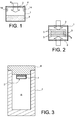
- the invention ( figure 1 ) is in the form of a box delimited by an envelope (1) comprising at least one opening, each opening being closed by a filter (2).
- the envelope (1) contains active means (3) for trapping hydrogen, and an unoccupied volume (4) overlooking the filter (2).
- the box is typically placed in a containment enclosure whose contents, not shown in the figures, is subjected to radiolysis or thermolysis which constantly produces hydrogen but also poison gases harmful to the proper functioning of the active means, such as CO, HC1 or HF.
- the active means may be metal hydrides such as ZrCO or Zr2Fe, or metal oxides. They may be, among other things, a free state and divided at the bottom of the box or, as shown in figure 2 , in coating plates (5) separated suspended from inside the envelope (1).
- the envelope (1) comprises a double opening and therefore a pair of filters (2) closing them.
- the box can be placed anywhere, for example ( figure 3 ) in the containment enclosure (9) of a packaging (7) in the form of a container closed by an upper lid (6): it can in particular be hooked under the lid (6), the filter (2) facing the internal volume of the confinement chamber (9) at the top of it: the hydrogen forming tends to rise and to go to the box, where it is captured.
- the filter (2) includes, going from the outside to the inside of the box and as shown in the figure 6 , typically a porous substrate (11) ensuring its rigidity and possibly being a metal sinter or made of ceramic, a microporous layer (13) for stopping certain poisons and a metal filtering membrane (12) for flammable gases, the microporous layer ( 13) is then between the metal membrane (12) and the substrate (11), which is the outermost of the filter (2).
- the metal membrane (12) may be, among others, based on palladium which has the ability to carry out the filtration of hydrogen by the chemical route according to the process described above. The hydrogen then passes through the metal membrane (12) according to this process.
- Other metal alloys some of which have already been mentioned, have similar filtering properties.
- the microporous layer (13) is intended to protect the palladium, or more generally the material of the metal membrane (12), by stopping or slowing down the gases that can poison it, such as CO; it can be made of silica.
- the composite filter as described combining the metal membrane and the microporous layer can be made by depositing palladium on a silica layer, the assembly being supported by the porous substrate.
- the filter (2) consists of a porous substrate and a microporous layer (13), which works by purely molecular filtration according to the steric exclusion process described above.
- the microporous layer may however be permeable to certain gases or small molecules, such as poison gases, such as HCl. These gases can then enter the envelope (1) and hinder the proper functioning of the active means (3).
- Additional traps (14) may be added inside the casing (1) to fix these gases; however, under certain circumstances, you may choose to place them outside the envelope.
- An interesting trapping material, with respect to the gases mentioned above, are carbonates. Desiccants may also be added in the envelope (1).
Landscapes
- Chemical & Material Sciences (AREA)
- Engineering & Computer Science (AREA)
- Organic Chemistry (AREA)
- Chemical Kinetics & Catalysis (AREA)
- Inorganic Chemistry (AREA)
- Analytical Chemistry (AREA)
- Combustion & Propulsion (AREA)
- Physics & Mathematics (AREA)
- General Chemical & Material Sciences (AREA)
- Oil, Petroleum & Natural Gas (AREA)
- High Energy & Nuclear Physics (AREA)
- General Engineering & Computer Science (AREA)
- Plasma & Fusion (AREA)
- Environmental & Geological Engineering (AREA)
- Emergency Management (AREA)
- Business, Economics & Management (AREA)
- Health & Medical Sciences (AREA)
- Biomedical Technology (AREA)
- Life Sciences & Earth Sciences (AREA)
- General Life Sciences & Earth Sciences (AREA)
- Geology (AREA)
- Separation Using Semi-Permeable Membranes (AREA)
- Separation Of Gases By Adsorption (AREA)
- Gas Separation By Absorption (AREA)
Description
- Le sujet de l'invention est un dispositif de piégeage de gaz inflammables produits par radiolyse ou thermolyse, ou les deux, dans une enceinte de confinement formée dans un emballage ou un autre système destiné au transport et/ou l'entreposage de matières radioactives. Un tel gaz, couramment produit par ces phénomènes, est l'hydrogène.
- Les installations nucléaires donnent naissance à une certaine quantité de « déchets technologiques » qui peuvent comprendre des objets et des matériaux de natures très diverses tels que des filtres, des déchets métalliques, des gravats, des verres, etc., ou encore des matières organiques à base de cellulose comme du papier, du bois, du coton, ou de matières plastiques telles que des housses de conditionnement en vinyle ou en polyuréthane, des bottes, des gants et des objets divers en matière dite polymère. Tous ces déchets peuvent également enfermer de petites quantités de liquides tels que de l'eau et des liquides organiques comme l'huile ou des hydrocarbures. Ils constituent tous des matières, soit activées pendant leur séjour dans les installations nucléaires, soit contaminées par de la poudre de radioéléments dont l'uranium ou le plutonium lors de leur utilisation dans ces installations, ces radioéléments pouvant émettre des particules α, β, γ...
- Le transport et le stockage de ces déchets technologiques posent une difficulté spécifique liée à la nature des matières transportées. En effet, comme précédemment écrit, ces déchets sont contaminés par des radioéléments dont l'uranium ou le plutonium qui leur confère un caractère radioactif. Sous l'effet de l'irradiation générée par les radioéléments, les matériaux constituant les déchets peuvent se dégrader et libérer des composés gazeux dont certains sont inflammables. Parmi les gaz produits on trouve de l'hydrogène, du monoxyde et du dioxyde de carbone, de l'oxygène, de l'azote ainsi que des composés organiques volatils (COV). Ce phénomène est appelé radiolyse. La production de tels gaz inflammables pose problème lorsque les déchets technologiques sont confinés dans une enceinte fermée de volume réduit, puisqu'ils peuvent atteindre rapidement une concentration élevée sans possibilité d'évacuation. Dans le cas de l'hydrogène, le seuil d'inflammabilité dans l'air est situé autour de 4%. Lorsque la concentration dépasse ce seuil, une source de chaleur ou une étincelle peut suffire à enflammer le mélange gazeux ou à produire une déflagration violente.
- Diverses études et observations ont montré que la concentration des gaz inflammables, tels que l'hydrogène produit par radiolyse dans une enceinte fermée contenant des matières radioactives à composants hydrogénés, peut parfois atteindre des valeurs d'environ 4% au bout de quelques jours, comme lorsque les déchets technologiques émettent des particules α intenses et contiennent de nombreuses molécules organiques.
- L'état de la technique antérieure comprend divers dispositifs de piégeage de gaz inflammables tels que l'hydrogène, notamment par une oxydation catalytique qui produit une recombinaison de l'oxygène et de l'hydrogène en eau.
- Le brevet
FR-A-2 874 120 - L'inconvénient de ces recombineurs par oxydation est qu'ils fonctionnent seulement si le ciel gazeux contient de l'oxygène en quantité suffisante, ce qui n'est pas toujours vrai, puisque la radiolyse des matières organiques (chaînes carbonées notamment) ne produit pas d'oxygène, et au contraire l'oxygène présent peut être consommé par des réactions d'oxydation de la matière organique.
- Le brevet
FR-A-2 925 752 - D'autres piégeurs comprennent des hydrures métalliques ou des oxydes métalliques, appelés moyens actifs ou « getters » qui piègent les gaz inflammables sans utiliser d'oxygène. Ces moyens actifs peuvent être réversibles (cas des hydrures métalliques) ou irréversibles (cas des oxydes métalliques). Dans le premier cas, le gaz inflammable peut être relâché dans des conditions de pression de températures spécifiques. Un inconvénient de ces moyens actifs est toutefois que leur efficacité est fortement réduite en présence de gaz poisons, et notamment, de nouveau, de CO. Or, la dégradation thermochimique et radiolytique des déchets polymériques engendre dans presque tous les cas des concentrations importantes de tels poisons.
- Les documents
US-A-6 262 328 etWO-A-2010/066811 décrivent en conséquence des moyens actifs enrobés dans des matrices poreuses qui ont la faculté de filtrer le mélange en arrêtant les poisons tout en permettant au gaz à piéger d'atteindre les moyens actifs. De telles matrices peuvent être des matrices vitreuses, cimentaires, ou des zéolites perméables à l'hydrogène. Un certain manque d'efficacité doit toutefois être regretté, puisqu'il est difficile d'optimiser la répartition des moyens actifs dans la matrice pour permettre un piégeage efficace : des quantités importantes de produit actif sont donc nécessaires. De plus, si le produit actif ne donne plus satisfaction, notamment s'il est saturé, il est impossible de le remplacer seul, la matrice devant l'être aussi. - Il existe encore des dispositifs de filtration fondés sur des membranes microporeuses ou autres, mais qui ne concernent pas les conditions de l'invention puisqu'ils ne concernent pas des enceintes confinées et reposent sur l'établissement de courants gazeux ou de différences de pression pour forcer un écoulement à travers les membranes. On citera par exemple le document
EP-A-0 383 153 , où un produit catalyseur est disposé à travers une ouverture de l'enveloppe dans laquelle l'hydrogène est produit : le catalyseur est enfermé dans un boîtier, muni d'une grille à la sortie et d'un filtre en chandelle, qui est cependant perméable à tous les gaz du mélange du côté de l'enveloppe ; les gaz en surpression dans l'enveloppe traversent donc le filtre et le catalyseur avant de s'écouler à l'extérieur, l'hydrogène ayant été éliminé, ici encore par recombinaison pour produire de l'eau. - Le document
EP-A-0 670 575 décrit un autre dispositif où le catalyseur est déposé à l'intérieur d'un boîtier, qui est clos sauf à un filtre. Ce dispositif ne résout toutefois pas le problème de l'empoisonnement du catalyseur, de sorte qu'il doit rester isolé du milieu de production des gaz jusqu'à ce qu'une irruption d'hydrogène soit constatée. Il est alors exposé à ce milieu. La nécessité d'une surveillance et d'une manipulation du piège ou d'un mécanisme quand le piège doit devenir actif est un gros inconvénient pour des procédés de très longue durée où l'apparition de l'hydrogène peut être imprévisible, ou au contraire lente et régulière, ce qui imposerait de laisser le piège toujours actif pour éviter son accumulation. Il apparaît que le filtre n'exerce aucun effet sélectif sur les gaz et est un simple filtre à particules (HEPA). Il est douteux qu'une bonne efficacité puisse être obtenue si le piège est activé pendant peu de temps au lieu de l'être en permanence. - L'idée de base de l'invention consiste à introduire dans l'enceinte de confinement d'un emballage dans laquelle se produisent la radiolyse et/ou la thermolyse une boîte dont au moins une des faces est équipée d'un filtre sélectif du mélange pour laisser passer les gaz inflammables et notamment l'hydrogène. Le produit actif de piégeage de l'hydrogène est placé dans la boîte et est donc isolé des poisons gazeux par le filtre. Le contenu de la boîte est idéalement formé des gaz inflammables purs si la filtration est parfaite. Le filtre a la double fonction d'arrêter ou de ralentir certains au moins des autres gaz du mélange, et notamment d'arrêter le monoxyde de carbone qui est un poison de la réaction catalytique, et de produire un gradient de pression partielle entre l'intérieur et l'extérieur de la boîte, puisque les gaz inflammables sont piégés à mesure qu'ils pénètrent dans la boîte. On obtient donc un système où l'hydrogène présent dans l'enceinte de confinement est conduit dans la boîte par le gradient de pression partielle à mesure qu'il se forme d'une part, et qu'il est piégé d'autre part, alors que les gaz poisons ne pénètrent pas ou très difficilement dans la boîte. La « boîte » est également appelée « enveloppe » dans la suite de la description.
- Un aspect de l'invention est donc un dispositif de piégeage de gaz inflammables et notamment de l'hydrogène (et ses formes isotopiques, à savoir les formes deutériées, tritiées ou encore mixtes, deutériées et tritiées) produits par radiolyse et/ou thermolyse dans une enceinte de confinement formée dans un système de transport et/ou d'entreposage de matières radioactives (ce système pouvant être un emballage de déchets, un conteneur de combustible irradié, ou autre), le dispositif comportant une enveloppe délimitant une cavité dans laquelle se situent des moyens actifs aptes à piéger les gaz inflammables, l'enveloppe étant continue hormis à au moins une ouverture qui est occupée par un filtre et communiquant exclusivement avec l'enceinte de confinement, le filtre laissant passer les gaz inflammables, caractérisé en ce que le filtre ralentit ou arrête d'autres gaz et notamment arrête le monoxyde de carbone.
- Les moyens actifs peuvent être constitués d'un hydrure ou d'un oxyde métallique ; ils peuvent être à un état divisé et libre dans l'enveloppe, ou disposés en revêtement de surface de plaques internes à l'enveloppe, ce qui garantit que les moyens actifs sont bien accessibles, permettant notamment leur remplacement lorsqu'ils sont saturés, contrairement aux dispositifs où ils sont enrobés dans des matrices.
- Le filtre peut être constitué d'une couche microporeuse, la filtration se faisant alors selon un processus d'exclusion stérique, celui-ci inhibant ou retardant la diffusion des molécules de taille importante et favorisant la diffusion des molécules de taille les plus faibles. Les gaz inflammables comportant des molécules de taille moins importante que celle des gaz poisons, la diffusion de ces derniers dans la couche microporeuse est alors sensiblement retardée, voire arrêtée, alors que celle des gaz inflammables est, au contraire, favorisée.
- Le filtre peut être complété par une membrane métallique située sous le filtre principal et qui le complète ; la filtration par la membrane laisse passer les gaz inflammables seulement et arrête tous les autres gaz grâce au mode chimique de la filtration. Celle-ci est alors réalisée selon un processus d'absorption des gaz inflammables sur la surface de la membrane, dissociation, diffusion à travers la membrane, recombinaison et désorption. Après avoir traversé toute l'épaisseur de la membrane métallique, les gaz inflammables se retrouvent ainsi au sein de l'enveloppe.
- Le filtre garde toute son utilité puisqu'il arrête certains gaz pouvant empêcher par empoisonnement le bon fonctionnement de la membrane métallique, dont, encore, le monoxyde de carbone.
- Les filtres comprennent souvent un substrat poreux sans propriétés de filtration particulière mais assurant leur résistance mécanique.
- La couche microporeuse peut être constituée de silice, la membrane métallique pouvant être en palladium, palladium-nickel, palladium-argent, palladium-cuivre, ou encore vanadium-tungstène et vanadium-nickel.
- Si la sélectivité du filtre est jugée insuffisante, l'enveloppe peut encore contenir des produits de piégeage de certains poisons des moyens actifs, comme du carbonate.
- L'invention sera maintenant décrite à titre purement illustratif en liaison aux figures suivantes :
- la
figure 1 est une vue générale d'une réalisation de l'invention, - la
figure 2 représente une autre réalisation de l'invention, - les
figures 3 ,4 et 5 illustrent deux façons particulières d'agencer l'invention, - et la
figure 6 illustre le filtre. - L'invention (
figure 1 ) se présente sous forme d'une boîte délimitée par une enveloppe (1) comprenant au moins une ouverture, chaque ouverture étant obturée par un filtre (2). L'enveloppe (1) contient des moyens actifs (3) de piégeage de l'hydrogène, et un volume inoccupé (4) donnant sur le filtre (2). La boîte est typiquement placée dans une enceinte de confinement dont le contenu, non représenté sur les figures, est soumis à une radiolyse ou une thermolyse qui produit constamment de l'hydrogène mais également des gaz poisons néfastes au bon fonctionnement des moyens actifs, tels que CO, HC1 ou encore HF. Les moyens actifs peuvent être des hydrures métalliques tels que le ZrCO ou encore le Zr2Fe, ou des oxydes métalliques. Ils peuvent être, entre autres dispositions, à un état libre et divisé au fond de la boîte ou, comme on le représente à lafigure 2 , en revêtement de plaques (5) séparées suspendues à l'intérieur de l'enveloppe (1). Dans cette réalisation, l'enveloppe (1) comprend une ouverture double et donc une paire de filtres (2) les obturant. - La boîte peut être placée à un endroit quelconque, par exemple (
figure 3 ) dans l'enceinte de confinement (9) d'un emballage (7) en forme de conteneur clos par un couvercle (6) supérieur : elle peut notamment être accrochée sous le couvercle (6), le filtre (2) donnant sur le volume interne de l'enceinte de confinement (9) au sommet de celui-ci : l'hydrogène se formant tend à s'élever et à se diriger vers la boîte, où il est capté. - D'autres dispositions sont cependant concevables sans changer la nature de l'invention, comme celle que l'on représente à la
figure 4 , où la boîte est placée dans le couvercle (6) de l'emballage (7) ; la boîte (8), contenant les moyens actifs (3), donne alors sur l'intérieur de l'emballage (7), par l'intermédiaire du filtre (2), et sur l'extérieur par l'intermédiaire d'un petit couvercle (10) continu, rendu étanche par un joint (15), mais qui peut être retiré pour remplacer les moyens actifs (3). Une autre possibilité, représentée à lafigure 5 , consisterait à placer la boîte hors de l'emballage (7 ) en reliant l'intérieur de la boîte et celui de l'emballage par un conduit (16) ; le conduit (16) et l'ouverture de l'enveloppe (1) coïncident, de sorte que le filtre (2) obture aussi le conduit (16). - On va maintenant passer à la description du filtre (2). Il comprend, en allant de l'extérieur vers l'intérieur de la boîte et comme le montre la
figure 6 , typiquement un substrat poreux (11) assurant sa rigidité et pouvant être un fritté métallique ou réalisé en céramique, une couche microporeuse (13) permettant d'arrêter certains poisons et une membrane métallique de filtration (12) des gaz inflammables, la couche microporeuse (13) se situant alors entre la membrane métallique (12) et le substrat (11), qui est le plus à l'extérieur du filtre (2). La membrane métallique (12) peut être, entre autres, à base de palladium qui a la faculté de réaliser la filtration de l'hydrogène par la voie chimique selon le processus décrit précédemment. L'hydrogène traverse alors la membrane métallique (12) selon ce processus. D'autres alliages métalliques, dont certains ont déjà été mentionnés, possèdent des propriétés semblables de filtration. - La couche microporeuse (13) est destinée à protéger le palladium, ou plus généralement la matière de la membrane métallique (12), en arrêtant ou ralentissant les gaz pouvant l'empoisonner comme le CO ; elle peut être réalisée en silice. Le filtre composite tel que décrit combinant membrane métallique et couche microporeuse peut être réalisé par un dépôt de palladium sur une couche en silice, l'ensemble étant supporté par le substrat poreux.
- Selon un second mode de réalisation, le filtre (2) est constitué d'un substrat poreux et d'une couche microporeuse (13), qui travaille par filtration purement moléculaire selon le processus d'exclusion stérique décrit précédemment. La couche microporeuse peut toutefois être perméable à certains gaz ou molécules de faibles dimensions, tels que des gaz poisons, comme HCl. Ces gaz peuvent alors entrer dans l'enveloppe (1) et gêner le bon fonctionnement des moyens actifs (3). Des pièges supplémentaires (14) peuvent être ajoutés à l'intérieur de l'enveloppe (1) pour fixer ces gaz ; on peut toutefois, dans certaines circonstances, choisir de les placer à l'extérieur de l'enveloppe. Un matériau de piégeage intéressant, à l'égard des gaz mentionnés ci-dessus, sont les carbonates. Des dessicants peuvent aussi être ajoutés dans l'enveloppe (1).
Claims (10)
- Dispositif de piégeage de gaz inflammables produits par radiolyse et/ou thermolyse dans une enceinte de confinement formée dans un système (7) de transport et/ou d'entreposage de matières radioactives, le dispositif comportant une enveloppe (1) délimitant une cavité dans laquelle se situent des moyens actifs (3) aptes à piéger les gaz inflammables, l'enveloppe étant continue hormis à au moins une ouverture qui est occupée par un filtre et communiquant exclusivement avec l'enceinte de confinement, le filtre (2) laissant passer les gaz inflammables, caractérisé en ce que le filtre ralentit ou arrête d'autres gaz et arrête le monoxyde de carbone.
- Dispositif de piégeage de gaz selon la revendication 1, caractérisé en ce qu'il comprend, dans l'enveloppe, et placée sur l'ouverture, une membrane métallique (12) réalisant une filtration laissant passer seulement les gaz inflammables et placée entre ledit filtre et les moyens actifs.
- Dispositif de piégeage de gaz selon la revendication 1, caractérisé en ce qu'il comprend, dans l'enveloppe, des pièges (14) pour fixer des gaz à molécules de faibles dimensions ayant traversé le filtre (2).
- Dispositif de piégeage de gaz selon la revendication 3, caractérisé en ce que les pièges sont constitués de carbonate.
- Dispositif de piégeage de gaz selon l'une quelconque des revendications 1 à 4, caractérisé en ce que le filtre est constitué par une couche microporeuse (13).
- Dispositif de piégeage de gaz selon la revendication 5, caractérisé en ce que la couche microporeuse (13) est constituée de silice.
- Dispositif de piégeage de gaz selon l'une quelconque des revendications 1 à 6, caractérisé en ce que le filtre comprend un substrat poreux (11).
- Dispositif de piégeage de gaz selon l'une quelconque des revendications 1 à 7, caractérisé en ce que les moyens actifs sont constitués d'un hydrure ou d'un oxyde métallique.
- Dispositif de piégeage de gaz selon l'une quelconque des revendications 1 à 8, caractérisé en ce que les moyens actifs sont à un état divisé et libre dans l'enveloppe.
- Dispositif de piégeage de gaz selon l'une quelconque des revendications 1 à 8, caractérisé en ce que les moyens actifs sont disposés en revêtement de surfaces de plaques (5) internes à l'enveloppe.
Applications Claiming Priority (2)
| Application Number | Priority Date | Filing Date | Title |
|---|---|---|---|
| FR1151136A FR2971614A1 (fr) | 2011-02-11 | 2011-02-11 | Dispositif de piegeage de gaz inflammables produits par radiolyse ou thermolyse dans une enceinte de confinement |
| PCT/EP2012/052342 WO2012107576A1 (fr) | 2011-02-11 | 2012-02-10 | Dispositif de piegeage de gaz inflammables produits par radiolyse ou thermolyse dans une enceinte de confinement |
Publications (2)
| Publication Number | Publication Date |
|---|---|
| EP2673782A1 EP2673782A1 (fr) | 2013-12-18 |
| EP2673782B1 true EP2673782B1 (fr) | 2015-03-11 |
Family
ID=45567033
Family Applications (1)
| Application Number | Title | Priority Date | Filing Date |
|---|---|---|---|
| EP12702853.8A Active EP2673782B1 (fr) | 2011-02-11 | 2012-02-10 | Dispositif de piegeage de gaz inflammables produits par radiolyse ou thermolyse dans une enceinte de confinement |
Country Status (8)
| Country | Link |
|---|---|
| US (1) | US8956443B2 (fr) |
| EP (1) | EP2673782B1 (fr) |
| JP (1) | JP6215710B2 (fr) |
| KR (1) | KR101932199B1 (fr) |
| CN (1) | CN103890858B (fr) |
| ES (1) | ES2539375T3 (fr) |
| FR (1) | FR2971614A1 (fr) |
| WO (1) | WO2012107576A1 (fr) |
Families Citing this family (6)
| Publication number | Priority date | Publication date | Assignee | Title |
|---|---|---|---|---|
| FR3014861B1 (fr) | 2013-12-18 | 2017-05-05 | Tn Int | Piege a hydrogene, issu de reactions de radiolyse |
| JP6228498B2 (ja) * | 2014-03-27 | 2017-11-08 | 日立Geニュークリア・エナジー株式会社 | 水素排出装置を備える放射性廃棄物収納容器及び水素排出装置 |
| JP6242263B2 (ja) * | 2014-03-27 | 2017-12-06 | 日立Geニュークリア・エナジー株式会社 | 放射性物質の保管容器 |
| GB2526563A (en) * | 2014-05-28 | 2015-12-02 | Nat Nuclear Lab Ltd | Improved storage of nuclear waste materials |
| US9700829B1 (en) | 2016-02-29 | 2017-07-11 | Savannah River Nuclear Solutions, Llc | Method of capturing or trapping zinc using zinc getter materials |
| CN106268307A (zh) * | 2016-10-20 | 2017-01-04 | 中国船舶重工集团公司第七八研究所 | 一种盒式催化单元 |
Family Cites Families (31)
| Publication number | Priority date | Publication date | Assignee | Title |
|---|---|---|---|---|
| DE3121125C2 (de) * | 1981-05-27 | 1986-04-10 | Kernforschungsanlage Jülich GmbH, 5170 Jülich | Verfahren zum Abtrennen von Wasserstoff und/oder Deuterium und Tritium aus einem Inertgasstrom sowie Vorrichtung zur Durchführung des Verfahrens im Kühlgaskreislauf eines gasgekühlten Kernreaktors |
| JPS6178422A (ja) * | 1984-09-25 | 1986-04-22 | Fuji Electric Co Ltd | 酸性ガスの選択的除去方法 |
| JPH0688765B2 (ja) * | 1986-09-04 | 1994-11-09 | 松下電器産業株式会社 | 希ガス精製装置 |
| DE3904149C2 (de) * | 1989-02-11 | 1994-01-20 | Kernforschungsz Karlsruhe | Vorrichtung an Behältern mit radioaktiven Abfällen zur Verringerung des Innendrucks durch Wasserstoffbildung |
| IT1248676B (it) * | 1990-06-01 | 1995-01-26 | Getters Spa | Recupero di trizio e deuterio dai loro ossidi e composti intermetallici utili a questo scopo |
| US5353949A (en) * | 1992-09-21 | 1994-10-11 | Pall Corporation | Vent filter assembly |
| US6033632A (en) * | 1993-12-08 | 2000-03-07 | Eltron Research, Inc. | Solid state oxygen anion and electron mediating membrane and catalytic membrane reactors containing them |
| ES2079939T3 (es) * | 1993-12-13 | 1996-01-16 | Anlagen Und Reaktorsicherheit | Dispositivo para la eliminacion de hidrogeno libre de una mezcla gaseosa que contiene hidrogeno y oxigeno. |
| US6262328B1 (en) * | 1999-06-11 | 2001-07-17 | Westinghouse Savannah River Company | Container and method for absorbing and reducing hydrogen concentration |
| US6544400B2 (en) * | 2000-03-30 | 2003-04-08 | Manhattan Scientifics, Inc. | Portable chemical hydrogen hydride system |
| BR0017205A (pt) * | 2000-03-31 | 2003-04-08 | David Systems Technology Sl | Sistema para o monitoramento e a eliminação de hidrogênio |
| US6575248B2 (en) * | 2000-05-17 | 2003-06-10 | Schlumberger Technology Corporation | Fuel cell for downhole and subsea power systems |
| US6686079B2 (en) * | 2000-05-17 | 2004-02-03 | Schlumberger Technology Corporation | Fuel cell for downhole power systems |
| JP2002054798A (ja) * | 2000-08-11 | 2002-02-20 | Honda Motor Co Ltd | 水素吸蔵合金式水素貯蔵タンクに水素ガスを充填する装置及び方法 |
| US7922781B2 (en) * | 2001-03-02 | 2011-04-12 | Chellappa Anand S | Hydrogen generation apparatus and method for using same |
| US6481747B1 (en) * | 2001-07-23 | 2002-11-19 | Trw Inc. | Cool, low effluent pyrotechnic inflator |
| US7344571B2 (en) * | 2003-08-14 | 2008-03-18 | The Gillette Company | Hydrogen generator |
| FR2874120B1 (fr) * | 2004-08-09 | 2006-11-24 | Cogema Logistics Sa | Procede et dispositif d'elimination des gaz inflammables dans une enceinte fermee et enceinte equipee d'un tel dispositif |
| CN101163586A (zh) * | 2005-02-17 | 2008-04-16 | 泽斯吸气剂公司 | 柔性多层吸气器 |
| US8408246B2 (en) * | 2005-10-05 | 2013-04-02 | Societe Bic | Fuel cartridge for fuel cells |
| US7779856B2 (en) * | 2005-10-05 | 2010-08-24 | Societe Bic | Fuel cartridge of a fuel cell with fuel stored outside fuel liner |
| US20070205111A1 (en) * | 2005-10-31 | 2007-09-06 | Nanscopic Technologies, Inc. | Apparatus And Method For Producing Hydrogen |
| US20070256361A1 (en) * | 2006-05-08 | 2007-11-08 | Alchemix Corporation | Method for the gasification of hydrocarbon feedstocks |
| CN2901504Y (zh) * | 2006-05-25 | 2007-05-16 | 中国船舶重工集团公司第七一八研究所 | 一种无须外部提供能源的氢与氧复合装置 |
| CN101134158B (zh) * | 2006-08-31 | 2011-07-06 | 比亚迪股份有限公司 | 一种用于分离氢气的复合膜及其制备方法和氢气分离器 |
| FR2909657B1 (fr) * | 2006-12-12 | 2009-03-06 | Commissariat Energie Atomique | Composition minerale apte a pieger l'hydrogene, procede de preparation et utilisations |
| FR2925752B1 (fr) | 2007-12-21 | 2012-03-09 | Tn Int | Dispositif de transport et/ou de stockage de matieres radioactives concu pour permettre la liberation controlee d'oxygene dans une enceinte fermee |
| JP2009162574A (ja) * | 2007-12-28 | 2009-07-23 | Toshiba Corp | 放射性廃棄物の収納容器及び収納方法 |
| FR2931142B1 (fr) * | 2008-05-15 | 2010-08-20 | Commissariat Energie Atomique | Procede de fabrication d'un reservoir d'hydrogene a hydrures metalliques |
| FR2939700B1 (fr) | 2008-12-11 | 2014-09-12 | Commissariat Energie Atomique | Materiau pour le piegeage d'hydrogene, procede de preparation et utilisations |
| EP4181241A1 (fr) * | 2011-04-05 | 2023-05-17 | Brilliant Light Power, Inc. | Système de génération d'énergie électrochimique à base de h20 à catalyseur d'hydrogène |
-
2011
- 2011-02-11 FR FR1151136A patent/FR2971614A1/fr not_active Withdrawn
-
2012
- 2012-02-10 JP JP2013552975A patent/JP6215710B2/ja active Active
- 2012-02-10 EP EP12702853.8A patent/EP2673782B1/fr active Active
- 2012-02-10 ES ES12702853.8T patent/ES2539375T3/es active Active
- 2012-02-10 KR KR1020137020646A patent/KR101932199B1/ko active Active
- 2012-02-10 CN CN201280005418.0A patent/CN103890858B/zh active Active
- 2012-02-10 US US13/984,094 patent/US8956443B2/en active Active
- 2012-02-10 WO PCT/EP2012/052342 patent/WO2012107576A1/fr not_active Ceased
Also Published As
| Publication number | Publication date |
|---|---|
| EP2673782A1 (fr) | 2013-12-18 |
| JP6215710B2 (ja) | 2017-10-18 |
| CN103890858A (zh) | 2014-06-25 |
| KR20140037809A (ko) | 2014-03-27 |
| WO2012107576A1 (fr) | 2012-08-16 |
| KR101932199B1 (ko) | 2018-12-24 |
| CN103890858B (zh) | 2016-06-15 |
| JP2014510905A (ja) | 2014-05-01 |
| ES2539375T3 (es) | 2015-06-30 |
| US8956443B2 (en) | 2015-02-17 |
| US20130312610A1 (en) | 2013-11-28 |
| FR2971614A1 (fr) | 2012-08-17 |
Similar Documents
| Publication | Publication Date | Title |
|---|---|---|
| EP2673782B1 (fr) | Dispositif de piegeage de gaz inflammables produits par radiolyse ou thermolyse dans une enceinte de confinement | |
| JP2846517B2 (ja) | 水素と酸素の再結合装置 | |
| US8147760B1 (en) | Portable chemical oxygen generator | |
| US8029738B2 (en) | Method and device for removing inflammable gases in a closed chamber and chamber equipped with such a device | |
| FR2783507A1 (fr) | Sachet etanche a la poussiere pour produits pulverulents fins | |
| EP1730052B1 (fr) | Dispositif de distribution, unite par unite, d'objets conformes tels que comprimes pharmaceutiques | |
| WO2009083491A1 (fr) | Dispositif de transport et/ou de stockage de matieres radioactives conçu pour permettre la liberation commandee d'oxygene dans une enceinte fermee | |
| EP2605249A1 (fr) | Procédé et dispositif de réduction du dégazage de déchets tritiés issus de l'industrie nucléaire | |
| EP2311044B1 (fr) | Procede de traitement d'une structure contenant du sodium et une matiere radioactive | |
| CN113825567A (zh) | 用于保存活性物质的器皿以及相应的盖和容器 | |
| US6413304B1 (en) | Drum vent filter | |
| EP0468880B1 (fr) | Dispositif de conditionnement de systèmes absorbeurs d'oxygène et/ou relargueurs de CO2 | |
| FR3030861B1 (fr) | Centrale nucleaire | |
| FR3014861A1 (fr) | Piege a hydrogene, issu de reactions de radiolyse | |
| FR2914558A1 (fr) | Dispositif de traitement d'air par photocatalyse en compartiment | |
| FR2856723A1 (fr) | Container de securite pour le transport de valeurs | |
| EP1507716A1 (fr) | Materiau d emballage a cavite, notamment pour matiere vegeta le | |
| FR2777381A1 (fr) | Procede de filtration physico-chimique des aerosols, gaz, et vapeurs radioactifs contenus dans un air contamine | |
| CA2944271A1 (fr) | Materiau constitue d'une preparation comprenant du ferrocene. | |
| BE406940A (fr) | ||
| FR2626708A1 (fr) | Procede et dispositif de protection d'une structure contre un deversement de metal liquide chaud et fortement reducteur | |
| FR2727288A1 (fr) | Procede et dispositif pour la generation retardee d'un gaz de fumigation | |
| FR2891262A1 (fr) | Procede et dispositif de conservation et de distribution d'un produit dans un recepient ferme. | |
| FR3049473A1 (fr) | Element de filtration pour un systeme domestique de purification d'air | |
| BE617882A (fr) |
Legal Events
| Date | Code | Title | Description |
|---|---|---|---|
| PUAI | Public reference made under article 153(3) epc to a published international application that has entered the european phase |
Free format text: ORIGINAL CODE: 0009012 |
|
| 17P | Request for examination filed |
Effective date: 20130812 |
|
| AK | Designated contracting states |
Kind code of ref document: A1 Designated state(s): AL AT BE BG CH CY CZ DE DK EE ES FI FR GB GR HR HU IE IS IT LI LT LU LV MC MK MT NL NO PL PT RO RS SE SI SK SM TR |
|
| RIN1 | Information on inventor provided before grant (corrected) |
Inventor name: LEONI, ELISA Inventor name: ROHR, VALENTIN Inventor name: LATROCHE, MICHEL Inventor name: PRIGENT, JOCELYN |
|
| DAX | Request for extension of the european patent (deleted) | ||
| RIN1 | Information on inventor provided before grant (corrected) |
Inventor name: LEONI, ELISA Inventor name: ROHR, VALENTIN Inventor name: PRIGENT, JOCELYN Inventor name: LATROCHE, MICHEL |
|
| RIC1 | Information provided on ipc code assigned before grant |
Ipc: B01J 20/06 20060101ALI20140807BHEP Ipc: C01B 3/50 20060101ALI20140807BHEP Ipc: B01D 53/46 20060101ALI20140807BHEP Ipc: B01D 53/22 20060101ALI20140807BHEP Ipc: B01D 53/04 20060101ALI20140807BHEP Ipc: B01J 20/02 20060101ALI20140807BHEP Ipc: C01B 3/00 20060101ALI20140807BHEP Ipc: B01D 53/62 20060101ALI20140807BHEP Ipc: G21C 19/317 20060101ALI20140807BHEP Ipc: B01D 53/68 20060101ALI20140807BHEP Ipc: G21C 9/06 20060101AFI20140807BHEP |
|
| GRAP | Despatch of communication of intention to grant a patent |
Free format text: ORIGINAL CODE: EPIDOSNIGR1 |
|
| INTG | Intention to grant announced |
Effective date: 20140915 |
|
| GRAS | Grant fee paid |
Free format text: ORIGINAL CODE: EPIDOSNIGR3 |
|
| GRAA | (expected) grant |
Free format text: ORIGINAL CODE: 0009210 |
|
| AK | Designated contracting states |
Kind code of ref document: B1 Designated state(s): AL AT BE BG CH CY CZ DE DK EE ES FI FR GB GR HR HU IE IS IT LI LT LU LV MC MK MT NL NO PL PT RO RS SE SI SK SM TR |
|
| REG | Reference to a national code |
Ref country code: GB Ref legal event code: FG4D Free format text: NOT ENGLISH |
|
| REG | Reference to a national code |
Ref country code: CH Ref legal event code: EP |
|
| REG | Reference to a national code |
Ref country code: CH Ref legal event code: NV Representative=s name: BOVARD AG, CH |
|
| REG | Reference to a national code |
Ref country code: IE Ref legal event code: FG4D Free format text: LANGUAGE OF EP DOCUMENT: FRENCH |
|
| REG | Reference to a national code |
Ref country code: AT Ref legal event code: REF Ref document number: 715711 Country of ref document: AT Kind code of ref document: T Effective date: 20150415 |
|
| REG | Reference to a national code |
Ref country code: DE Ref legal event code: R096 Ref document number: 602012005829 Country of ref document: DE Effective date: 20150423 |
|
| REG | Reference to a national code |
Ref country code: SE Ref legal event code: TRGR |
|
| REG | Reference to a national code |
Ref country code: NL Ref legal event code: T3 |
|
| REG | Reference to a national code |
Ref country code: ES Ref legal event code: FG2A Ref document number: 2539375 Country of ref document: ES Kind code of ref document: T3 Effective date: 20150630 |
|
| PG25 | Lapsed in a contracting state [announced via postgrant information from national office to epo] |
Ref country code: FI Free format text: LAPSE BECAUSE OF FAILURE TO SUBMIT A TRANSLATION OF THE DESCRIPTION OR TO PAY THE FEE WITHIN THE PRESCRIBED TIME-LIMIT Effective date: 20150311 Ref country code: HR Free format text: LAPSE BECAUSE OF FAILURE TO SUBMIT A TRANSLATION OF THE DESCRIPTION OR TO PAY THE FEE WITHIN THE PRESCRIBED TIME-LIMIT Effective date: 20150311 Ref country code: LT Free format text: LAPSE BECAUSE OF FAILURE TO SUBMIT A TRANSLATION OF THE DESCRIPTION OR TO PAY THE FEE WITHIN THE PRESCRIBED TIME-LIMIT Effective date: 20150311 Ref country code: NO Free format text: LAPSE BECAUSE OF FAILURE TO SUBMIT A TRANSLATION OF THE DESCRIPTION OR TO PAY THE FEE WITHIN THE PRESCRIBED TIME-LIMIT Effective date: 20150611 |
|
| REG | Reference to a national code |
Ref country code: AT Ref legal event code: MK05 Ref document number: 715711 Country of ref document: AT Kind code of ref document: T Effective date: 20150311 |
|
| REG | Reference to a national code |
Ref country code: LT Ref legal event code: MG4D |
|
| PG25 | Lapsed in a contracting state [announced via postgrant information from national office to epo] |
Ref country code: LV Free format text: LAPSE BECAUSE OF FAILURE TO SUBMIT A TRANSLATION OF THE DESCRIPTION OR TO PAY THE FEE WITHIN THE PRESCRIBED TIME-LIMIT Effective date: 20150311 Ref country code: GR Free format text: LAPSE BECAUSE OF FAILURE TO SUBMIT A TRANSLATION OF THE DESCRIPTION OR TO PAY THE FEE WITHIN THE PRESCRIBED TIME-LIMIT Effective date: 20150612 Ref country code: RS Free format text: LAPSE BECAUSE OF FAILURE TO SUBMIT A TRANSLATION OF THE DESCRIPTION OR TO PAY THE FEE WITHIN THE PRESCRIBED TIME-LIMIT Effective date: 20150311 |
|
| PG25 | Lapsed in a contracting state [announced via postgrant information from national office to epo] |
Ref country code: EE Free format text: LAPSE BECAUSE OF FAILURE TO SUBMIT A TRANSLATION OF THE DESCRIPTION OR TO PAY THE FEE WITHIN THE PRESCRIBED TIME-LIMIT Effective date: 20150311 Ref country code: SK Free format text: LAPSE BECAUSE OF FAILURE TO SUBMIT A TRANSLATION OF THE DESCRIPTION OR TO PAY THE FEE WITHIN THE PRESCRIBED TIME-LIMIT Effective date: 20150311 Ref country code: PT Free format text: LAPSE BECAUSE OF FAILURE TO SUBMIT A TRANSLATION OF THE DESCRIPTION OR TO PAY THE FEE WITHIN THE PRESCRIBED TIME-LIMIT Effective date: 20150713 Ref country code: RO Free format text: LAPSE BECAUSE OF FAILURE TO SUBMIT A TRANSLATION OF THE DESCRIPTION OR TO PAY THE FEE WITHIN THE PRESCRIBED TIME-LIMIT Effective date: 20150311 |
|
| PG25 | Lapsed in a contracting state [announced via postgrant information from national office to epo] |
Ref country code: AT Free format text: LAPSE BECAUSE OF FAILURE TO SUBMIT A TRANSLATION OF THE DESCRIPTION OR TO PAY THE FEE WITHIN THE PRESCRIBED TIME-LIMIT Effective date: 20150311 Ref country code: PL Free format text: LAPSE BECAUSE OF FAILURE TO SUBMIT A TRANSLATION OF THE DESCRIPTION OR TO PAY THE FEE WITHIN THE PRESCRIBED TIME-LIMIT Effective date: 20150311 Ref country code: IS Free format text: LAPSE BECAUSE OF FAILURE TO SUBMIT A TRANSLATION OF THE DESCRIPTION OR TO PAY THE FEE WITHIN THE PRESCRIBED TIME-LIMIT Effective date: 20150711 |
|
| REG | Reference to a national code |
Ref country code: DE Ref legal event code: R097 Ref document number: 602012005829 Country of ref document: DE |
|
| PLBE | No opposition filed within time limit |
Free format text: ORIGINAL CODE: 0009261 |
|
| STAA | Information on the status of an ep patent application or granted ep patent |
Free format text: STATUS: NO OPPOSITION FILED WITHIN TIME LIMIT |
|
| PG25 | Lapsed in a contracting state [announced via postgrant information from national office to epo] |
Ref country code: DK Free format text: LAPSE BECAUSE OF FAILURE TO SUBMIT A TRANSLATION OF THE DESCRIPTION OR TO PAY THE FEE WITHIN THE PRESCRIBED TIME-LIMIT Effective date: 20150311 |
|
| 26N | No opposition filed |
Effective date: 20151214 |
|
| PG25 | Lapsed in a contracting state [announced via postgrant information from national office to epo] |
Ref country code: SI Free format text: LAPSE BECAUSE OF FAILURE TO SUBMIT A TRANSLATION OF THE DESCRIPTION OR TO PAY THE FEE WITHIN THE PRESCRIBED TIME-LIMIT Effective date: 20150311 |
|
| REG | Reference to a national code |
Ref country code: FR Ref legal event code: PLFP Year of fee payment: 5 |
|
| PG25 | Lapsed in a contracting state [announced via postgrant information from national office to epo] |
Ref country code: MC Free format text: LAPSE BECAUSE OF FAILURE TO SUBMIT A TRANSLATION OF THE DESCRIPTION OR TO PAY THE FEE WITHIN THE PRESCRIBED TIME-LIMIT Effective date: 20150311 Ref country code: LU Free format text: LAPSE BECAUSE OF FAILURE TO SUBMIT A TRANSLATION OF THE DESCRIPTION OR TO PAY THE FEE WITHIN THE PRESCRIBED TIME-LIMIT Effective date: 20160210 |
|
| REG | Reference to a national code |
Ref country code: IE Ref legal event code: MM4A |
|
| PG25 | Lapsed in a contracting state [announced via postgrant information from national office to epo] |
Ref country code: IE Free format text: LAPSE BECAUSE OF NON-PAYMENT OF DUE FEES Effective date: 20160210 |
|
| REG | Reference to a national code |
Ref country code: FR Ref legal event code: PLFP Year of fee payment: 6 |
|
| PG25 | Lapsed in a contracting state [announced via postgrant information from national office to epo] |
Ref country code: MT Free format text: LAPSE BECAUSE OF FAILURE TO SUBMIT A TRANSLATION OF THE DESCRIPTION OR TO PAY THE FEE WITHIN THE PRESCRIBED TIME-LIMIT Effective date: 20150311 |
|
| REG | Reference to a national code |
Ref country code: FR Ref legal event code: PLFP Year of fee payment: 7 |
|
| PG25 | Lapsed in a contracting state [announced via postgrant information from national office to epo] |
Ref country code: CY Free format text: LAPSE BECAUSE OF FAILURE TO SUBMIT A TRANSLATION OF THE DESCRIPTION OR TO PAY THE FEE WITHIN THE PRESCRIBED TIME-LIMIT Effective date: 20150311 Ref country code: SM Free format text: LAPSE BECAUSE OF FAILURE TO SUBMIT A TRANSLATION OF THE DESCRIPTION OR TO PAY THE FEE WITHIN THE PRESCRIBED TIME-LIMIT Effective date: 20150311 Ref country code: HU Free format text: LAPSE BECAUSE OF FAILURE TO SUBMIT A TRANSLATION OF THE DESCRIPTION OR TO PAY THE FEE WITHIN THE PRESCRIBED TIME-LIMIT; INVALID AB INITIO Effective date: 20120210 |
|
| PG25 | Lapsed in a contracting state [announced via postgrant information from national office to epo] |
Ref country code: MK Free format text: LAPSE BECAUSE OF FAILURE TO SUBMIT A TRANSLATION OF THE DESCRIPTION OR TO PAY THE FEE WITHIN THE PRESCRIBED TIME-LIMIT Effective date: 20150311 Ref country code: TR Free format text: LAPSE BECAUSE OF FAILURE TO SUBMIT A TRANSLATION OF THE DESCRIPTION OR TO PAY THE FEE WITHIN THE PRESCRIBED TIME-LIMIT Effective date: 20150311 |
|
| PG25 | Lapsed in a contracting state [announced via postgrant information from national office to epo] |
Ref country code: BG Free format text: LAPSE BECAUSE OF FAILURE TO SUBMIT A TRANSLATION OF THE DESCRIPTION OR TO PAY THE FEE WITHIN THE PRESCRIBED TIME-LIMIT Effective date: 20150311 |
|
| PG25 | Lapsed in a contracting state [announced via postgrant information from national office to epo] |
Ref country code: AL Free format text: LAPSE BECAUSE OF FAILURE TO SUBMIT A TRANSLATION OF THE DESCRIPTION OR TO PAY THE FEE WITHIN THE PRESCRIBED TIME-LIMIT Effective date: 20150311 |
|
| P01 | Opt-out of the competence of the unified patent court (upc) registered |
Effective date: 20230526 |
|
| REG | Reference to a national code |
Ref country code: DE Ref legal event code: R082 Ref document number: 602012005829 Country of ref document: DE Representative=s name: KANDLBINDER, MARKUS, DIPL.-PHYS., DE |
|
| PGFP | Annual fee paid to national office [announced via postgrant information from national office to epo] |
Ref country code: NL Payment date: 20250226 Year of fee payment: 14 |
|
| PGFP | Annual fee paid to national office [announced via postgrant information from national office to epo] |
Ref country code: DE Payment date: 20250226 Year of fee payment: 14 |
|
| PGFP | Annual fee paid to national office [announced via postgrant information from national office to epo] |
Ref country code: ES Payment date: 20250306 Year of fee payment: 14 |
|
| PGFP | Annual fee paid to national office [announced via postgrant information from national office to epo] |
Ref country code: SE Payment date: 20250226 Year of fee payment: 14 |
|
| PGFP | Annual fee paid to national office [announced via postgrant information from national office to epo] |
Ref country code: BE Payment date: 20250225 Year of fee payment: 14 |
|
| PGFP | Annual fee paid to national office [announced via postgrant information from national office to epo] |
Ref country code: IT Payment date: 20250226 Year of fee payment: 14 Ref country code: GB Payment date: 20250226 Year of fee payment: 14 |
|
| REG | Reference to a national code |
Ref country code: CH Ref legal event code: U11 Free format text: ST27 STATUS EVENT CODE: U-0-0-U10-U11 (AS PROVIDED BY THE NATIONAL OFFICE) Effective date: 20260331 |
|
| PGFP | Annual fee paid to national office [announced via postgrant information from national office to epo] |
Ref country code: FR Payment date: 20260223 Year of fee payment: 15 |
|
| PGFP | Annual fee paid to national office [announced via postgrant information from national office to epo] |
Ref country code: CH Payment date: 20260331 Year of fee payment: 15 Ref country code: CZ Payment date: 20260205 Year of fee payment: 15 |