EP2674548A2 - Dispositif d'acheminement pour produit en vrac et/ou matière fibreuse - Google Patents
Dispositif d'acheminement pour produit en vrac et/ou matière fibreuse Download PDFInfo
- Publication number
- EP2674548A2 EP2674548A2 EP13002940.8A EP13002940A EP2674548A2 EP 2674548 A2 EP2674548 A2 EP 2674548A2 EP 13002940 A EP13002940 A EP 13002940A EP 2674548 A2 EP2674548 A2 EP 2674548A2
- Authority
- EP
- European Patent Office
- Prior art keywords
- loosening
- shaft
- elements
- housing
- impact
- Prior art date
- Legal status (The legal status is an assumption and is not a legal conclusion. Google has not performed a legal analysis and makes no representation as to the accuracy of the status listed.)
- Withdrawn
Links
Images


Classifications
-
- E—FIXED CONSTRUCTIONS
- E04—BUILDING
- E04F—FINISHING WORK ON BUILDINGS, e.g. STAIRS, FLOORS
- E04F21/00—Implements for finishing work on buildings
- E04F21/02—Implements for finishing work on buildings for applying plasticised masses to surfaces, e.g. plastering walls
- E04F21/06—Implements for applying plaster, insulating material, or the like
- E04F21/08—Mechanical implements
- E04F21/085—Mechanical implements for filling building cavity walls with insulating materials
-
- E—FIXED CONSTRUCTIONS
- E04—BUILDING
- E04F—FINISHING WORK ON BUILDINGS, e.g. STAIRS, FLOORS
- E04F21/00—Implements for finishing work on buildings
- E04F21/02—Implements for finishing work on buildings for applying plasticised masses to surfaces, e.g. plastering walls
- E04F21/06—Implements for applying plaster, insulating material, or the like
- E04F21/08—Mechanical implements
- E04F21/12—Mechanical implements acting by gas pressure, e.g. steam pressure
Definitions
- the invention relates to a conveying device for bulk material and / or fiber material, in particular a blowing insulation conveying device, comprising a loosening device for loosening the bulk material and / or fiber material, wherein the loosening device comprises: a housing having a longitudinal axis, the conveying direction of the bulk material to be conveyed and / or fiber material, and at least one loosening element comprising a shaft which is rotatably mounted in the housing about an axis and driven by a motor, wherein the axis is arranged perpendicular to the longitudinal axis, wherein on the shaft a number of impact elements are rotatably mounted.
- a generic device is for example from the US 3,051,398 A known.
- a device of this type is used in particular to spend a fibrous insulating material - promoted in a stream of air - to its destination, for example, in hollow chambers, which are formed in a roof truss to fill said hollow chambers tightly with the insulating material.
- Such a device is further, for example, from the EP 1 520 948 A2 known.
- the material delivered pressed in a container is loosened up by the conveyor device by means of a chopper and the material thus prepared is conveyed in a transport line in the airstream to its destination.
- the device that accomplishes the loosening of the material is also referred to as a rotary valve.
- the fiber material may be cellulose. If, what has recently been preferred, the fiber material is made of wood, special difficulties arise. The wood fibers are pressed in turn, d. H. Delivered in highly compressed form, then as fanned wood fibers to Dämmstelle, for example, in hollow chambers of a roof, to be promoted. Due to the different structures of the fibrous wood particles, these do not disintegrate into individual fibers as easily as in the case of cellulose.
- the invention has for its object to provide a conveyor of the type mentioned in such a way that it is possible, even difficult ceremonimaschinende materials, in particular wood, sufficiently mecanicmaschinen and optimally promote, so that the volume to be filled with the fiber material well and Hohlstellen- can be filled freely.
- the initially highly compressed present insulating material is therefore to be frayed in an improved manner and distribute as evenly as possible in a compartment to be filled with him.
- the device should be simple in construction, so that a cost-effective production is possible.
- the housing is designed as a tube with a circular cross-section, wherein in the housing in the conveying direction consecutively at least two loosening elements, preferably three loosening elements are arranged, wherein two consecutive in the conveying direction Auflock ceremoniess institute for opposing rotation are formed, wherein the impact elements extend from the shaft to the inner circumference of the tubular housing, wherein in the conveying direction before and / or behind the last impact element, a device for blowing air is arranged.
- Said loosening device is provided as a separate element, which is effectively arranged between the device for loosening the pressed material (rotary valve) and the end of the fiber material blown-in hose.
- a preferred solution provides that two loosening elements following one another in the conveying direction rotate in opposite directions. Accordingly, in the case of three loosening elements, the first and the third loosening element rotate in the same direction, while the loosening element arranged therebetween rotates in opposite directions.
- the striking elements accordingly extend from the shaft to the inner periphery of the tubular housing. This is to be understood that only a sufficient gap for proper function between the radially outer end of the striking elements and the housing inner circumference remains when the striking element comes closest to the housing inner circumference.
- This gap is preferably in the range between 3 and 30 mm, preferably between 5 and 15 mm.
- the striking elements may extend radially away from the shaft. It is also possible for the impact elements to extend away from the shaft at least in sections at an angle, preferably between 10 ° and 50 °, to the radial direction.
- a particularly good loosening effect is achieved if a first loosening element is arranged in a region of the housing lying in the conveying direction, the impact elements extending radially away from the shaft of the first loosening element, and a second loosening element being arranged in a region following in the conveying direction wherein the striking elements extend from the shaft of the second loosening element away from the shaft at least in sections at an angle to the radial direction.
- the impact elements can be connected to each other at a location spaced from the shaft, for example by a ring having a slightly smaller diameter than the inner diameter of the tubular housing.
- the impact elements can be rotatably connected via a positive connection, in particular via a polygonal profile, with the shaft.
- a striking element can also be connected to a hub part, in particular welded, and the hub part can then be non-rotatably connected via the positive connection with the shaft.
- a further improvement of the loosening effect and improved further promotion of the fiberized material are achieved in that a device for blowing in air is arranged in the conveying direction before and / or behind the last impact element in the conveying direction.
- This device can be designed as a ring element, in which a number of air injection nozzles are arranged over the circumference. Angular adjustment of the air injection nozzles, the fiberized material can be imparted a twist in the delivery hose, which supports the promotion of the material.
- a particularly good defibration and promotion of the material is achieved when both said end of the loosening device and at the end of the tube each said means are provided for blowing air, preferably at the beginning of the loosening device.
- the impact elements of a loosening element which are arranged on the shaft, thus forming a kind of rotation grid, which is arranged rotationally driven in the housing.
- the tubular housing with the striking elements according to the invention which come close to the housing inner circumference, allows efficient fibrillation of the material to be conveyed with the significant advantage that there is a very compact and space-saving device that is easy to transport. This is important because of the purpose of the device since it must be mobile.
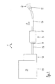
- a conveyor 1 for conveying wood fibers 2 is outlined.
- the wood fibers have a substantially linear extension and a length between about 2 and about 8 mm.
- the wood fibers 2 are delivered in a pressed state and are initially in a container 15. It is necessary to loosen up the present in a pressed state wood fibers and promote, for example, to bring them tightly packed in cavities of a roof truss can.
- the conveyor device 1 a device 12 for loosening the pressed wood fibers, which is sometimes referred to as a rotary valve.
- the device 12 performs a chopping process by which the fibers are loosened.
- the already partially frayed material 2 passes through a hose 13 in a conveying direction F to a loosening device 3.
- This device further loosens the fiber material 2 and brings it into a virtually completely frayed state.
- Via a further hose 14, the frayed material 2 is further blown in the conveying direction F to its destination.
- devices 11 for blowing in air are provided at three points, namely in front of the loosening device 3, behind the loosening device 3 and at the end of the hose 14.
- the devices 11 include nozzles that the Loosening and turbulence of the wood fibers 2 favor. If appropriate, further such devices 11 can be arranged in the flow or conveying path of the wood fibers 2.
- the loosening device 3 is outlined with different details.
- the loosening device 3, which constitutes a separate element in addition to the device 12, has a tubular housing 4 which has a longitudinal axis L.
- the longitudinal axis L coincides with the conveying direction F.
- the loosening elements 5 are rotating components which rotate about an axis a which is perpendicular to the longitudinal axis L.
- a shaft 6 is provided, which is rotatably mounted in the housing 4 by means of suitable bearings 16.
- a number of striking elements 8 are arranged in a rotationally fixed manner on the shaft 6.
- the rotary drive of the shaft 6 is effected by a motor 7, which preferably rotates the shaft between 2.500 and 4,000 revolutions per minute, in which case the two loosening elements 5 preferably rotate in opposite directions.
- the striking elements 8 can, as it Fig. 3 shows, so be arranged on the shaft 6, that they extend radially. Alternatively, it is also possible - and show that FIGS. 4 and 5 for two alternative embodiments - that the striking elements 8 extend away from the shaft 6 at an angle ⁇ to the radial direction.
- the impact elements 8 are presently designed as impact iron, for example, as rectangular in cross-section and otherwise rod-shaped components made of structural steel.
- a device 11 for blowing in air is also arranged (see Fig. 2 ).
- the optimally loosened or frayed wood fibers 2 can be conveyed efficiently into the tube 14.
- Fig. 6 is shown as the impact elements 8 with the shaft 6 rotatably and structurally easy to connect.
- the striking elements 8 - in this case two striking elements 8 extending in opposite directions from the shaft 6 - are welded to a hub part 10.
- the hub part 10 has a square-shaped recess which fits the cross-sectional shape of the shaft 6, which is designed accordingly as a square profile.
- a number of hub parts 10 are axially on the shaft. 6 deferred and fixed in a suitable manner, for. B. by material bond (welding).
Landscapes
- Engineering & Computer Science (AREA)
- Architecture (AREA)
- Civil Engineering (AREA)
- Structural Engineering (AREA)
- Disintegrating Or Milling (AREA)
- Filling Or Emptying Of Bunkers, Hoppers, And Tanks (AREA)
Applications Claiming Priority (1)
| Application Number | Priority Date | Filing Date | Title |
|---|---|---|---|
| DE102012012019A DE102012012019A1 (de) | 2012-06-16 | 2012-06-16 | Fördervorrichtung für Schüttgut und/oder Fasermaterial |
Publications (2)
| Publication Number | Publication Date |
|---|---|
| EP2674548A2 true EP2674548A2 (fr) | 2013-12-18 |
| EP2674548A3 EP2674548A3 (fr) | 2017-06-21 |
Family
ID=48672321
Family Applications (1)
| Application Number | Title | Priority Date | Filing Date |
|---|---|---|---|
| EP13002940.8A Withdrawn EP2674548A3 (fr) | 2012-06-16 | 2013-06-07 | Dispositif d'acheminement pour produit en vrac et/ou matière fibreuse |
Country Status (2)
| Country | Link |
|---|---|
| EP (1) | EP2674548A3 (fr) |
| DE (1) | DE102012012019A1 (fr) |
Cited By (1)
| Publication number | Priority date | Publication date | Assignee | Title |
|---|---|---|---|---|
| AT523481A1 (fr) * | 2020-02-05 | 2021-08-15 |
Citations (17)
| Publication number | Priority date | Publication date | Assignee | Title |
|---|---|---|---|---|
| US3051398A (en) | 1959-04-14 | 1962-08-28 | Marvin O Babb | Apparatus for preparing baled insulation material for gas entrainment |
| US4151961A (en) | 1977-01-06 | 1979-05-01 | Sperry Rand Corporation | Hay processing machine |
| DE3408179C2 (fr) | 1984-03-06 | 1990-04-26 | Inter-Wood-Maschinen Gmbh & Co Kg, 8923 Lechbruck, De | |
| DE4101352C1 (fr) | 1991-01-18 | 1992-01-02 | Pallmann Maschinenfabrik Gmbh & Co Kg, 6660 Zweibruecken, De | |
| DE29501353U1 (de) | 1995-01-28 | 1995-03-23 | X-Floc GmbH Dämmtechnik-Maschinen, 71272 Renningen | Maschine zum Befördern von Füll- und Dämmstoffen |
| US5829649A (en) | 1993-02-16 | 1998-11-03 | Western Fibers, Inc. | Apparatus for conditioning and dispensing loose fill insulation material |
| DE19822051C1 (de) | 1998-05-16 | 1999-09-23 | Thueringisches Inst Textil | Dosiervorrichtung für Kurzschnittfasern |
| DE10126840A1 (de) | 2001-06-01 | 2003-02-27 | B Bau Beat Blaesi Thal | Vorrichtung zum Zuführen von Schüttgut oder Fasermaterial aus einem Vorrat zu einer Fördereinheit |
| US20030234264A1 (en) | 2002-06-25 | 2003-12-25 | Ofer Landau | Dry food dispensing system |
| US6796457B2 (en) | 2002-05-14 | 2004-09-28 | Ark Seal, Llc | Material feeder |
| EP1520948A2 (fr) | 2003-09-17 | 2005-04-06 | Markus Gleixner | Appareil transporteur, installation mobile de remplissage et procédé pour soufflage de matériau isolant dans les espaces creux |
| DE102006050036A1 (de) | 2005-10-24 | 2007-05-31 | Finbark Oy | Verfahren und Vorrichtung zum Behandeln von Material |
| DE102006049201A1 (de) | 2006-10-18 | 2008-04-24 | Isocell Vertriebs Gmbh | Pressballenauflösemaschine |
| DE202009005452U1 (de) | 2009-04-08 | 2009-08-20 | Popp, Elmar | Vorrichtung zum Fördern und Einbringen von Füll- und Dämmstoffen |
| WO2011029904A1 (fr) | 2009-09-11 | 2011-03-17 | Theurl Leimholzbau Gmbh | Système pour amener des fibres de bois dans un état permettant le traitement par des dispositifs de dosage, matière à base de fibres de bois préparée et produit extrudé produit à partir de cette matière |
| US7938348B2 (en) | 2004-07-27 | 2011-05-10 | Owens Corning Intellectual Capital, Llc | Loosefill blowing machine with a chute |
| US7967227B2 (en) | 2006-10-16 | 2011-06-28 | Owens-Corning Fiberglas Technology Inc. | Agitation system for blowing wool machine |
-
2012
- 2012-06-16 DE DE102012012019A patent/DE102012012019A1/de not_active Withdrawn
-
2013
- 2013-06-07 EP EP13002940.8A patent/EP2674548A3/fr not_active Withdrawn
Patent Citations (17)
| Publication number | Priority date | Publication date | Assignee | Title |
|---|---|---|---|---|
| US3051398A (en) | 1959-04-14 | 1962-08-28 | Marvin O Babb | Apparatus for preparing baled insulation material for gas entrainment |
| US4151961A (en) | 1977-01-06 | 1979-05-01 | Sperry Rand Corporation | Hay processing machine |
| DE3408179C2 (fr) | 1984-03-06 | 1990-04-26 | Inter-Wood-Maschinen Gmbh & Co Kg, 8923 Lechbruck, De | |
| DE4101352C1 (fr) | 1991-01-18 | 1992-01-02 | Pallmann Maschinenfabrik Gmbh & Co Kg, 6660 Zweibruecken, De | |
| US5829649A (en) | 1993-02-16 | 1998-11-03 | Western Fibers, Inc. | Apparatus for conditioning and dispensing loose fill insulation material |
| DE29501353U1 (de) | 1995-01-28 | 1995-03-23 | X-Floc GmbH Dämmtechnik-Maschinen, 71272 Renningen | Maschine zum Befördern von Füll- und Dämmstoffen |
| DE19822051C1 (de) | 1998-05-16 | 1999-09-23 | Thueringisches Inst Textil | Dosiervorrichtung für Kurzschnittfasern |
| DE10126840A1 (de) | 2001-06-01 | 2003-02-27 | B Bau Beat Blaesi Thal | Vorrichtung zum Zuführen von Schüttgut oder Fasermaterial aus einem Vorrat zu einer Fördereinheit |
| US6796457B2 (en) | 2002-05-14 | 2004-09-28 | Ark Seal, Llc | Material feeder |
| US20030234264A1 (en) | 2002-06-25 | 2003-12-25 | Ofer Landau | Dry food dispensing system |
| EP1520948A2 (fr) | 2003-09-17 | 2005-04-06 | Markus Gleixner | Appareil transporteur, installation mobile de remplissage et procédé pour soufflage de matériau isolant dans les espaces creux |
| US7938348B2 (en) | 2004-07-27 | 2011-05-10 | Owens Corning Intellectual Capital, Llc | Loosefill blowing machine with a chute |
| DE102006050036A1 (de) | 2005-10-24 | 2007-05-31 | Finbark Oy | Verfahren und Vorrichtung zum Behandeln von Material |
| US7967227B2 (en) | 2006-10-16 | 2011-06-28 | Owens-Corning Fiberglas Technology Inc. | Agitation system for blowing wool machine |
| DE102006049201A1 (de) | 2006-10-18 | 2008-04-24 | Isocell Vertriebs Gmbh | Pressballenauflösemaschine |
| DE202009005452U1 (de) | 2009-04-08 | 2009-08-20 | Popp, Elmar | Vorrichtung zum Fördern und Einbringen von Füll- und Dämmstoffen |
| WO2011029904A1 (fr) | 2009-09-11 | 2011-03-17 | Theurl Leimholzbau Gmbh | Système pour amener des fibres de bois dans un état permettant le traitement par des dispositifs de dosage, matière à base de fibres de bois préparée et produit extrudé produit à partir de cette matière |
Cited By (2)
| Publication number | Priority date | Publication date | Assignee | Title |
|---|---|---|---|---|
| AT523481A1 (fr) * | 2020-02-05 | 2021-08-15 | ||
| AT523481B1 (de) * | 2020-02-05 | 2022-02-15 | Clima-Super Vertriebsgmbh | Auflockerungsmaschine |
Also Published As
| Publication number | Publication date |
|---|---|
| DE102012012019A1 (de) | 2013-12-19 |
| EP2674548A3 (fr) | 2017-06-21 |
Similar Documents
| Publication | Publication Date | Title |
|---|---|---|
| EP3019276A1 (fr) | Broyeur à boulets à agitateur, muni de canaux axiaux | |
| DE102012209032A1 (de) | Fördertrommel der Tabak verarbeitenden Industrie | |
| DE102007049347B4 (de) | Verfahren zur Herstellung eines Vorformlings aus Halbzeug, zur Herstellung eines ringförmigen Rahmenprofils, Verwendung des Vefahrens, sowie Rahmenprofil | |
| EP2839083B9 (fr) | Pointe d'un pieu | |
| EP2614698A1 (fr) | Faucheuse | |
| DE2428588C2 (de) | Vorrichtung zum Beleimen von Spänen | |
| DE19746602B4 (de) | Spinnverfahren | |
| EP3155151B1 (fr) | Buse de filage pour un métier à filer à jet d'air et métier à filer à jet d'air avec buse de filage correspondante | |
| EP2674548A2 (fr) | Dispositif d'acheminement pour produit en vrac et/ou matière fibreuse | |
| DE102008024553A1 (de) | Vorrichtung zum Einbringen von Additiven in einen zur Herstellung eines Rauchartikels vorgesehenen und bereits rundgeformten Strang | |
| DE3714212A1 (de) | Vorrichtung zum pneumatischen falschdrallspinnen mit einem streckwerk | |
| EP0472825A1 (fr) | Dispositif pour diviser un chapelet de saucisses formé par une machine de bourrage en saucisses | |
| EP2517582A2 (fr) | Bague d'aspiration pour un tambour de transport dans l'industrie de traitement du tabac | |
| EP1688176B1 (fr) | Dispositif de pompage et de mélange pour des matériaux en poudre et liquides et système pour la production des matériaux pâteuses destinés à la construction | |
| DE202014011136U1 (de) | Sauglanze für die Absaugung von rieselfähigen Schüttgütern | |
| AT521690B1 (de) | Vorrichtung zum Fördern und Auswerfen von Schüttgut oder Schnee | |
| DE3403964A1 (de) | Vorrichtung zum oe-friktionsspinnen | |
| EP0625671A1 (fr) | Procédé et dispositif d'assainissement d'un conduit enterré | |
| DE102006057290B4 (de) | Tabakzerfaserung mit zweiseitig gelagerter Förderschneckenwelle | |
| EP0298519B1 (fr) | Procédé et dispositif d'emmagasinage d'un ruban de fibres textiles dans un pot | |
| EP2865615B1 (fr) | Silo avec système de remplissage | |
| DE2842131B2 (de) | Schrämwalze | |
| DE102010039479A1 (de) | Schneidvorrichtung einer Strangmaschine der Tabak verarbeitenden Industrie | |
| DE102004040720B4 (de) | Exzenterschneckenpumpe | |
| DE1940722B2 (de) | Rotor fuer duennschichtbehandlungsapparat |
Legal Events
| Date | Code | Title | Description |
|---|---|---|---|
| PUAI | Public reference made under article 153(3) epc to a published international application that has entered the european phase |
Free format text: ORIGINAL CODE: 0009012 |
|
| AK | Designated contracting states |
Kind code of ref document: A2 Designated state(s): AL AT BE BG CH CY CZ DE DK EE ES FI FR GB GR HR HU IE IS IT LI LT LU LV MC MK MT NL NO PL PT RO RS SE SI SK SM TR |
|
| AX | Request for extension of the european patent |
Extension state: BA ME |
|
| PUAL | Search report despatched |
Free format text: ORIGINAL CODE: 0009013 |
|
| AK | Designated contracting states |
Kind code of ref document: A3 Designated state(s): AL AT BE BG CH CY CZ DE DK EE ES FI FR GB GR HR HU IE IS IT LI LT LU LV MC MK MT NL NO PL PT RO RS SE SI SK SM TR |
|
| AX | Request for extension of the european patent |
Extension state: BA ME |
|
| RIC1 | Information provided on ipc code assigned before grant |
Ipc: E04F 21/12 20060101ALI20170512BHEP Ipc: E04F 21/08 20060101AFI20170512BHEP |
|
| STAA | Information on the status of an ep patent application or granted ep patent |
Free format text: STATUS: THE APPLICATION IS DEEMED TO BE WITHDRAWN |
|
| 18D | Application deemed to be withdrawn |
Effective date: 20171222 |