EP2839083B9 - Pointe d'un pieu - Google Patents
Pointe d'un pieu Download PDFInfo
- Publication number
- EP2839083B9 EP2839083B9 EP13716208.7A EP13716208A EP2839083B9 EP 2839083 B9 EP2839083 B9 EP 2839083B9 EP 13716208 A EP13716208 A EP 13716208A EP 2839083 B9 EP2839083 B9 EP 2839083B9
- Authority
- EP
- European Patent Office
- Prior art keywords
- drive point
- pile
- set forth
- driving
- concrete
- Prior art date
- Legal status (The legal status is an assumption and is not a legal conclusion. Google has not performed a legal analysis and makes no representation as to the accuracy of the status listed.)
- Active
Links
Images

Classifications
-
- E—FIXED CONSTRUCTIONS
- E02—HYDRAULIC ENGINEERING; FOUNDATIONS; SOIL SHIFTING
- E02D—FOUNDATIONS; EXCAVATIONS; EMBANKMENTS; UNDERGROUND OR UNDERWATER STRUCTURES
- E02D5/00—Bulkheads, piles, or other structural elements specially adapted to foundation engineering
- E02D5/72—Pile shoes
-
- E—FIXED CONSTRUCTIONS
- E02—HYDRAULIC ENGINEERING; FOUNDATIONS; SOIL SHIFTING
- E02D—FOUNDATIONS; EXCAVATIONS; EMBANKMENTS; UNDERGROUND OR UNDERWATER STRUCTURES
- E02D5/00—Bulkheads, piles, or other structural elements specially adapted to foundation engineering
- E02D5/22—Piles
- E02D5/34—Concrete or concrete-like piles cast in position ; Apparatus for making same
- E02D5/38—Concrete or concrete-like piles cast in position ; Apparatus for making same making by use of mould-pipes or other moulds
-
- E—FIXED CONSTRUCTIONS
- E02—HYDRAULIC ENGINEERING; FOUNDATIONS; SOIL SHIFTING
- E02D—FOUNDATIONS; EXCAVATIONS; EMBANKMENTS; UNDERGROUND OR UNDERWATER STRUCTURES
- E02D5/00—Bulkheads, piles, or other structural elements specially adapted to foundation engineering
- E02D5/66—Mould-pipes or other moulds
- E02D5/665—Mould-pipes or other moulds for making piles
Definitions
- the invention relates to a Rammspitze for a substantially tubular, in particular hollow cylindrical, driven pile with a pile core through which concrete can be introduced into the pile, the ram tip is attachable to a pile end of the pile, wherein on an inner wall of the Rammspitze at least a first bearing web a first bearing surface is arranged for an end face of the pile end.
- Such Rammspitzen are used in the construction industry for the production of pile foundations.
- the individual piles which are usually made of ductile cast iron and have predetermined lengths of, for example, five meters, are plugged into each other to produce a pile foundation.
- the piles In order to facilitate the nesting of piles and thus the extension of a pile foundation, the piles usually have a conically tapered first pile end and a second pile end formed into a sleeve.
- pile by pile can be driven into the ground, which can be produced quickly and inexpensively pile foundations of any length.
- Piles of this type are usually produced in a centrifugal casting process with a shaping rotating mold. This results in substantially cylindrical tubular piles, which are hollow inside. Depending on the type of use, these hollow cylindrical ramming piles can be filled or encased with concrete or another suitable grout after being grounded to produce a stable foundation.
- a ram tip is slipped onto the first driven pile, whose outer diameter is larger than the outer diameter of the driven pile.
- an annular space can be generated during ramming, which can be filled up by a compression with the injection material or concrete.
- a pumpable concrete mortar which usually has a grain size of up to 4 mm, is conveyed through the hollow pile core of the driven pile to the pile base and pressed into the ground at the ramming point.
- the concrete grouting takes place simultaneously with the pile pile and is completed upon reaching the final depth of the pile foundation.
- the object of the invention is to provide an improved Rammspitze can be made with the pile foundations while avoiding the disadvantages described above.
- the ram point can be plugged onto a pile end of the pile pile.
- concrete mortar or another suitable injection material can be introduced into the annular space between the outer diameter of the ramming tip and the outer diameter of the driven pile during ramming, without corresponding cuts or openings having to be made in the jacket of the driven pile.
- the Rammpfahl need not be manipulated when using a Rammspitze according to the invention, whereby no unwanted weakening of the pipe cross-section of the driven pile takes place.
- the ram point at least partially, preferably completely, made of cast iron and has a substantially rotationally symmetrical outer shape, wherein the axis of rotation extends substantially in Einrammraum. If an outer diameter of the ram tip in the driving direction substantially continuously reduced, a pile foundation with the use of a proposed Rammrade can be particularly easily rammed. Of course, however, it can also be provided that the outside diameter of the ram tip is essentially constant along its extension in the direction of insertion.
- the at least one first support web is formed in cross-section to the Einrammutter as a circular segment or annulus segment. It is advantageous if a circular arc of the circular segment or annulus segment extends over less than 340 °, preferably over 40 ° to 120 °, more preferably over 70 ° to 90 °.
- a plurality of concrete outlet channels preferably three concrete outlet channels, is or are provided.
- two concrete outlet channels of the plurality of concrete outlet channels are arranged in cross section to the Einrammcardi along the inner wall of the Rammspitze substantially equidistant to each other.
- the concrete outlet channels can also be arranged along the inner wall of the Rammspitze that they have irregular distances from one another.
- At least one radially inwardly projecting supporting device may be provided on the inner wall.
- the at least one radially inwardly projecting support device may be formed as a plurality of support ribs.
- At the Rammrade at least a second support web is arranged with a second bearing surface for an end face of a pile end, in Einrammcardi the distance of the second bearing surface from the edge of the ram tip is greater than the distance of the first bearing surface from the edge of the ram tip.
- the first and second bearing surfaces lie in the same plane.
- the first and second bearing surfaces can preferably lie in a plane parallel to a cross-sectional plane transversely to the direction of insertion E.
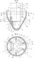
- Fig. 1 a shows a longitudinal section of a proposed Rammspitze 1 along a Einrammutter E and Fig. 1b shows a cross section along section line AA.
- the Rammspitze 1 is made in one piece in this example and is made of ductile cast iron.
- the outer shape of the Rammspitze 1 is rotationally symmetrical with respect to the rotation axis R formed.
- the Rammspitze 1 has an outer diameter D which is greater than an outer diameter D P of a pinned Rammpfahls 2.
- the outer diameter D of Rammspitze 1 decreases in the direction of its end truncated cone, whereby the ramming of a pile foundation with plugged Rammrade 1 is facilitated.
- the first bearing surfaces 7 of the first support webs 6 lie in one plane and form a defined stop for the end face 8 of a pile end 4 of a pinned Rammpfahls 2.
- the driven pile 2 in Einrammutter E so far attached to the Rammrade 1 be until the end face 8 of the pile pile 2 rests against the first bearing surfaces 7 of the first support webs 6.
- the maximum insertion depth of the driven pile 2 in Einrammutter E results from the distance T from the upper edge 11 of the Rammrade 1 to the plane of the first bearing surfaces. 7
- a cavity 9 is formed in the Rammspitze 1, which extends in Einrammcardi E. Between the cavity 9 and the upper edge 11 of the Rammrade 1 three concrete outlet channels 10 are formed in this example. This makes it possible that in the production of a pile foundation concrete mortar, which is introduced through the pile core 3 of the driven pile 2 and penetrates via the end face 8 in the cavity 9, passes through the concrete outlet channels 10 to the outer wall of the driven pile 2 and thus the production of a Mantelverpressung allows.
- Fig. 1b shows the Rammrade 1 the Fig. 1 a in a cross-sectional view along section line AA of Fig. 1 a.
- the stop arranged at a distance T from the upper edge 11 of the ramming tip 1 in the direction of insertion E for the end face 8 of the driven pile 2 is formed by a total of three first bearing surfaces 7.
- Each of the three first support webs 6 is formed in cross section to the Einrammcardi E as a circular ring segment.
- the circular arc 12 of each circular segment extends in each case over a diaper area of 80 ° and the three circular arcs 12 are arranged distributed uniformly along an imaginary circle.
- each concrete outlet channel 10 is arranged between each two first support webs 6, a concrete outlet channel 10 is arranged.
- two concrete outlet channels 10 along the inner wall 5 of the Rammspitze 1 are arranged substantially at equal distances from each other.
- each concrete outlet channel 10 extends over a Angular range of 40 °.
- a plurality of support ribs are arranged as supporting devices 13 on the 5.
- Fig. 2a shows a possible development of a Rammspitze 1 according to Fig. 1 a.
- this embodiment additionally has second support webs 6 'for a second driven pile 2' with a different outer diameter D P 'relative to the driven pile 2.
- Each second support web 6 ' has a second bearing surface 7', wherein the sum of the second bearing surfaces 7 'forms a defined stop for the end face 8' of the second driven pile 2 '.
- the distance T 'of the second bearing surfaces 7' from the edge 11 of Rammspitze 1 is greater than the distance T of the first bearing surfaces 7 from the edge 11 of Rammrade 1.
- both bearing surfaces 7, 7 'in the same Lie flat In this case, only the width of a bearing surface 7, 7 'in the radial direction would need to be chosen so large that it is suitable for the entire bandwidth of the outer diameter D P , D P ' of the driven piles 2, 2 'to be used.
- Fig. 2b shows the Rammrade 1 the Fig. 2a in a cross-sectional view along section line AA. It can be seen that the bearing surfaces 7, 7 'corresponding to the different outer diameter D P , D P ' of the driven piles 2, 2 'have a different radial distance from the axis of rotation R of the Rammspitze 1.
- the structural design of the Rammspitze 1 shown, however, is otherwise similar to the Rammrade 1 of Fig. 1 b.
Landscapes
- Engineering & Computer Science (AREA)
- Structural Engineering (AREA)
- Life Sciences & Earth Sciences (AREA)
- General Life Sciences & Earth Sciences (AREA)
- Mining & Mineral Resources (AREA)
- Paleontology (AREA)
- Civil Engineering (AREA)
- General Engineering & Computer Science (AREA)
- Piles And Underground Anchors (AREA)
- Placing Or Removing Of Piles Or Sheet Piles, Or Accessories Thereof (AREA)
- Addition Polymer Or Copolymer, Post-Treatments, Or Chemical Modifications (AREA)
Claims (12)
- Pointe d'un pieu (1) pour un pieu battu (2) essentiellement en forme de tube, plus particulièrement cylindrique creux, avec une âme de pieu (3), à travers laquelle du béton peut être introduit dans le pieu battu (2), dans laquelle la pointe de pieu (1) peut être fixée sur une extrémité de pieu (4) du pieu battu (2), dans laquelle sur une paroi interne (5) de la pointe de pieu (1) est disposée au moins une première entretoise d'appui (6) avec une première surface d'appui (7) pour une face frontale (8) de l'extrémité de pieu (4), dans laquelle la pointe de pieu (1) présente, à partir du niveau de la première surface d'appui (7), une cavité (9) s'étendant au moins partiellement dans un sens d'enfoncement par battage (E), dans laquelle, le pieu battu étant placé, du béton peut être introduit au travers de l'âme de pieu (3), dans laquelle au moins un canal de sortie du béton (10) est prévu, qui relie la cavité (9) avec un bord supérieur (11) de la pointe de pieu (1).
- Pointe d'un pieu selon la revendication 1, caractérisée en ce que la pointe de pieu (1) présente essentiellement une forme externe à symétrie de révolution, dans laquelle l'axe de rotation (R) passe essentiellement dans le sens d'enfoncement par battage (E).
- Pointe d'un pieu selon la revendication 1 ou 2, caractérisée en ce que la au moins une première entretoise d'appui (6) est conçue en section transversale par rapport au sens d'enfoncement par battage (E) comme un segment de cercle ou un segment de couronne.
- Pointe d'un pieu selon la revendication 3, caractérisée en ce qu'un arc de cercle (12) du segment de cercle ou du segment de couronne s'étend sur moins de 340°, de préférence plus de 40° à 120°, plus particulièrement, de préférence plus de 70° à 90°.
- Pointe d'un pieu selon l'une des revendications 1 à 4, caractérisée en ce qu'une pluralité de canaux de sortie de béton (10), de préférence trois canaux de sortie de béton (10), est ou sont prévu(s).
- Pointe d'un pieu selon la revendication 5, caractérisée en ce que, à chaque fois, deux canaux de sortie de béton (10) de la pluralité de canaux de sortie de béton (10) sont disposés les uns par rapport aux autres en section transversale par rapport au sens d'enfoncement par battage (E) le long de la paroi interne (5) de la pointe de pieu (1) essentiellement avec des écartements similaires.
- Pointe d'un pieu selon l'une des revendications 1 à 6, caractérisée en ce que sur la paroi interne (5) est prévu au moins un dispositif d'appui (13) faisant saillie radialement vers l'intérieur pour le centrage et / ou la fixation en position stable du pieu battu (2).
- Pointe d'un pieu selon la revendication 7, caractérisée en ce que le au moins un dispositif d'appui (13) faisant saillie radialement vers l'intérieur est conçu comme une pluralité de rainures d'appui.
- Pointe d'un pieu selon l'une des revendications 1 à 8, caractérisée en ce que sur la paroi interne (5) de la pointe de pieu (1) est disposée au moins une deuxième entretoise d'appui (6') avec une deuxième surface d'appui (7') pour une face frontale (8') d'une extrémité de pieu (4'), dans laquelle dans le sens d'enfoncement par battage (E), l'écartement (T') de la deuxième surface d'appui (7') du bord (11) de la pointe de pieu (1) est supérieur à l'écartement (T) de la première surface d'appui (7) du bord (11) de la pointe de sonnette (1).
- Pointe d'un pieu selon l'une des revendications 1 à 9, caractérisée en ce qu'un diamètre externe (D) de la pointe de pieu (1) dans le sens d'enfoncement par battage (E) se réduit essentiellement de façon continue.
- Pointe d'un pieu selon l'une des revendications 1 à 10, caractérisée en ce que la pointe de pieu (1) est réalisée d'une seule pièce.
- Pointe d'un pieu selon l'une des revendications 1 à 11, caractérisée en ce que la pointe de pieu (1) est composée au moins en partie, de préférence intégralement, de fonte.
Priority Applications (4)
| Application Number | Priority Date | Filing Date | Title |
|---|---|---|---|
| DE502013008877.4A DE502013008877C5 (de) | 2012-04-20 | 2013-04-12 | Rammspitze für pfahl |
| SI201330959T SI2839083T1 (en) | 2012-04-20 | 2013-04-12 | Pile shoe |
| HRP20180297TT HRP20180297T1 (hr) | 2012-04-20 | 2013-04-12 | Vrh stope pilota |
| PL13716208T PL2839083T3 (pl) | 2012-04-20 | 2013-04-12 | Ostrze wbijane dla pala |
Applications Claiming Priority (2)
| Application Number | Priority Date | Filing Date | Title |
|---|---|---|---|
| ATA485/2012A AT512161B1 (de) | 2012-04-20 | 2012-04-20 | Rammspitze für einen im Wesentlichen rohrförmigen, insbesondere hohlzylindrischen, Rammpfahl |
| PCT/EP2013/001069 WO2013156126A1 (fr) | 2012-04-20 | 2013-04-12 | Sabot de pointe pour pieu |
Publications (3)
| Publication Number | Publication Date |
|---|---|
| EP2839083A1 EP2839083A1 (fr) | 2015-02-25 |
| EP2839083B1 EP2839083B1 (fr) | 2017-11-22 |
| EP2839083B9 true EP2839083B9 (fr) | 2018-04-18 |
Family
ID=48095787
Family Applications (1)
| Application Number | Title | Priority Date | Filing Date |
|---|---|---|---|
| EP13716208.7A Active EP2839083B9 (fr) | 2012-04-20 | 2013-04-12 | Pointe d'un pieu |
Country Status (13)
| Country | Link |
|---|---|
| US (1) | US9725865B2 (fr) |
| EP (1) | EP2839083B9 (fr) |
| AT (1) | AT512161B1 (fr) |
| DE (1) | DE502013008877C5 (fr) |
| DK (1) | DK2839083T3 (fr) |
| ES (1) | ES2660386T3 (fr) |
| HR (1) | HRP20180297T1 (fr) |
| HU (1) | HUE035815T2 (fr) |
| PL (1) | PL2839083T3 (fr) |
| PT (1) | PT2839083T (fr) |
| SI (1) | SI2839083T1 (fr) |
| TR (1) | TR201802478T4 (fr) |
| WO (1) | WO2013156126A1 (fr) |
Families Citing this family (7)
| Publication number | Priority date | Publication date | Assignee | Title |
|---|---|---|---|---|
| BE1023258B1 (nl) * | 2016-03-15 | 2017-01-13 | Proferro Nv | Een tip voor een funderingspaal. |
| US10047490B2 (en) * | 2016-06-28 | 2018-08-14 | Tiroler Rohre GmbH | Drive point for a pile |
| US10240314B2 (en) * | 2017-06-16 | 2019-03-26 | William Eugene Hodge | Apparatus and method to enhance the utility of hydrodynamic compaction machine |
| CN109580374A (zh) * | 2019-01-03 | 2019-04-05 | 同济大学 | 评定含承压水砂层地下连续墙成槽稳定性离心模型试验装置 |
| DK3913143T3 (da) * | 2020-05-18 | 2023-06-12 | Rautaruukki Oyj | Drivpunkt og arrangement |
| CN115030213B (zh) * | 2022-05-26 | 2023-04-11 | 上海勘测设计研究院有限公司 | 一种适用于海上风电基桩的工装以及应用方法 |
| AT527410B1 (de) * | 2023-12-12 | 2025-02-15 | Tiroler Rohre GmbH | Zentrierhülse |
Family Cites Families (31)
| Publication number | Priority date | Publication date | Assignee | Title |
|---|---|---|---|---|
| US1352128A (en) * | 1915-09-01 | 1920-09-07 | Lawrence Mcguire | Concrete pile construction |
| US1366460A (en) * | 1920-01-17 | 1921-01-25 | Clarence S Howell | Pile |
| US1844871A (en) * | 1930-03-18 | 1932-02-09 | Schmedes George Peter | Driving point for piles and method of forming driven piles |
| US2016250A (en) * | 1933-02-28 | 1935-10-01 | Joseph Liberman | Blasting apparatus |
| US2146645A (en) * | 1936-01-27 | 1939-02-07 | William J Newman | Foundation construction |
| US2562860A (en) * | 1947-04-19 | 1951-07-31 | Dougherty J J | Shoe or tip for wooden piles |
| US2797466A (en) * | 1951-08-23 | 1957-07-02 | Lidberg Artur Robert | Improved mould for moulding concrete poles and the like |
| GB770612A (en) * | 1955-06-27 | 1957-03-20 | Mueller Ludwig | Improvements in or relating to piles |
| US3194328A (en) * | 1962-10-15 | 1965-07-13 | Foundation Specialties Inc | Pile driving hammer and boulder breaker, rock seating tool |
| US3306054A (en) * | 1964-08-24 | 1967-02-28 | John J Dougherty | Skirt type pile driving point |
| US3333428A (en) * | 1964-10-19 | 1967-08-01 | John J Dougherty | Open end cutting shoe |
| US3362171A (en) * | 1965-10-22 | 1968-01-09 | C W Blakeslee & Sons Inc | Method of forming a pile for building construction purposes and the product thereof |
| DE1914554C3 (de) * | 1968-03-21 | 1978-10-12 | Kabushiki Kaisha Takenaka Komuten, Osaka (Japan) | Verfahren zum Abdichten von Bodenformationen und Tiefbaukonstruktionen |
| US3690109A (en) * | 1970-03-16 | 1972-09-12 | Lee A Turzillo | Method and means for producing pile or like structural columns in situ |
| US3807184A (en) * | 1970-03-16 | 1974-04-30 | L Turzillo | Method and means for producing pile or like structural columns in situ |
| JPS5117204B2 (fr) * | 1971-11-08 | 1976-06-01 | ||
| US3869869A (en) * | 1973-11-26 | 1975-03-11 | Chen Paul Chuan Pao | Piling system |
| US3973409A (en) * | 1974-07-05 | 1976-08-10 | Kabushiki Kaisha Takechi Koumusho | Apparatus for establishing an anchor |
| JPS587022A (ja) * | 1981-07-03 | 1983-01-14 | 林 ▲あ▼哲 | 杭打設工法およびその装置 |
| US5018905A (en) * | 1985-12-11 | 1991-05-28 | Kinder William D | Foundation shoring method and means |
| DE3419517C2 (de) * | 1984-05-25 | 1993-09-30 | Zueblin Ag | Verfahren zum unterirdischen Einbau von Rohrleitungen und Vorrichtung zur Durchführung des Verfahrens |
| US4685834A (en) * | 1986-07-02 | 1987-08-11 | Sunohio Company | Splay bottom fluted metal piles |
| ATE182384T1 (de) * | 1994-01-06 | 1999-08-15 | Roxbury Ltd | Verbesserungen betreffend eine vorrichtung zum herstellen von pfählen |
| GB2364728B (en) * | 1998-05-16 | 2002-12-04 | Duncan Cuthill | Method of and apparatus for installing a pile underwater to create a mooring anchorage |
| US6814525B1 (en) * | 2000-11-14 | 2004-11-09 | Michael Whitsett | Piling apparatus and method of installation |
| WO2004053237A2 (fr) * | 2002-12-06 | 2004-06-24 | Geotechnical Reinforcement, Inc. | Procede de construction de jetees dans la terre et construction d'une jetee |
| US7338233B2 (en) * | 2003-12-18 | 2008-03-04 | Barrett Robert K | Soil nail and method of installing a subsurface support |
| US6951437B2 (en) * | 2004-02-20 | 2005-10-04 | Hall David B | Foundation support system and method |
| CN100478525C (zh) * | 2004-11-12 | 2009-04-15 | 丁锦良 | 一种复合管桩基础的施工方法 |
| US8602689B1 (en) * | 2011-06-03 | 2013-12-10 | Heli-Crete “Eco-Friendly” Piling Systems, Llc | Retractable nose cone system and method for forming reinforced concrete pilings and/or an electrical grounding system |
| US9598833B2 (en) * | 2011-08-26 | 2017-03-21 | American Piledriving Equipment, Inc. | Apparatus and methods for pipe piling placement with continuous grouting |
-
2012
- 2012-04-20 AT ATA485/2012A patent/AT512161B1/de not_active IP Right Cessation
-
2013
- 2013-04-12 DE DE502013008877.4A patent/DE502013008877C5/de active Active
- 2013-04-12 SI SI201330959T patent/SI2839083T1/en unknown
- 2013-04-12 ES ES13716208.7T patent/ES2660386T3/es active Active
- 2013-04-12 HU HUE13716208A patent/HUE035815T2/en unknown
- 2013-04-12 DK DK13716208.7T patent/DK2839083T3/en active
- 2013-04-12 WO PCT/EP2013/001069 patent/WO2013156126A1/fr not_active Ceased
- 2013-04-12 HR HRP20180297TT patent/HRP20180297T1/hr unknown
- 2013-04-12 TR TR2018/02478T patent/TR201802478T4/tr unknown
- 2013-04-12 PT PT137162087T patent/PT2839083T/pt unknown
- 2013-04-12 EP EP13716208.7A patent/EP2839083B9/fr active Active
- 2013-04-12 PL PL13716208T patent/PL2839083T3/pl unknown
-
2014
- 2014-10-08 US US14/509,369 patent/US9725865B2/en active Active
Also Published As
| Publication number | Publication date |
|---|---|
| US20150023739A1 (en) | 2015-01-22 |
| EP2839083B1 (fr) | 2017-11-22 |
| DE502013008877C5 (de) | 2026-03-26 |
| PL2839083T3 (pl) | 2018-05-30 |
| EP2839083A1 (fr) | 2015-02-25 |
| SI2839083T1 (en) | 2018-04-30 |
| DK2839083T3 (en) | 2018-02-19 |
| ES2660386T3 (es) | 2018-03-22 |
| HUE035815T2 (en) | 2018-05-28 |
| AT512161A4 (de) | 2013-06-15 |
| HRP20180297T1 (hr) | 2018-04-20 |
| WO2013156126A1 (fr) | 2013-10-24 |
| PT2839083T (pt) | 2018-02-26 |
| US9725865B2 (en) | 2017-08-08 |
| TR201802478T4 (tr) | 2018-03-21 |
| AT512161B1 (de) | 2013-06-15 |
Similar Documents
| Publication | Publication Date | Title |
|---|---|---|
| EP2839083B9 (fr) | Pointe d'un pieu | |
| EP1767729A1 (fr) | Structure de tour | |
| EP0013911B1 (fr) | Cheville en matière plastique | |
| EP1591596B1 (fr) | Goujon noyé | |
| DE2200512C3 (de) | Abstandhalter fur Bewehrungsstäbe | |
| EP3433448B1 (fr) | Élément d'échafaudage muni d'une tête de support et échafaudage équipé d'un tel élément d'échafaudage | |
| AT527410B1 (de) | Zentrierhülse | |
| AT516480B1 (de) | Vorrichtung zum Abschließen einer Pfahlrohrgründung | |
| DE112013001151B4 (de) | Schwingungsübertragungs-Unterdrückungsverfahren | |
| DE202010004381U1 (de) | Druckrohr sowie daraus hergestellter Erdanker | |
| EP0459167A1 (fr) | Assemblage pour fixer un boulon d'ancrage dans une forure | |
| DE20105013U1 (de) | Ankerhülse zur Injektionsbefestigung | |
| EP2022932A1 (fr) | Tête de traction | |
| DE102016107899B4 (de) | Verfahren zum Herstellen einer Rohrspundwand und Tragrohr | |
| EP3556944B1 (fr) | Cadre de couverture de puits, dispositif de couverture de puits, dispositif de puits et procédé d'installation | |
| EP3848512B1 (fr) | Procédé de création d'un élément de fondation dans le sol et élément de fondation | |
| DE2711899B2 (de) | Vorrichtung für die Bodeninjektion bei Hochdruck-Bodenvermörtelungen und PfahlgrUndungen | |
| DE10119988B4 (de) | Verdübelungs-Vorrichtung für die Ringelemente einer Tübbingauskleidung für unterirdische Bauwerke | |
| DE4315837C2 (de) | Verfahren und Vorrichtung zur segmentweisen Herstellung von Schlitzwänden im Tiefbau | |
| DE602004005262T2 (de) | Einrichtung zum formen eines Pfahls im Boden zwecks Fundament- oder Spundbohlenwerken | |
| EP1835091A2 (fr) | Tuyau d'écartement pour tirants d'ancrage | |
| CH710018A2 (de) | Betonschraubpfahl sowie Verfahren zu dessen Herstellung. | |
| EP2634439B1 (fr) | Douille perforée pour une cheville | |
| DE625897C (de) | Mehrteiliger Vortreibkern zum Eintreiben von Blechhuelsen fuer Ortpfaehle | |
| DE1634419A1 (de) | Vorrichtung zum Herausziehen metallischer in den Erdboden eingerammter Formrohre od.dgl. |
Legal Events
| Date | Code | Title | Description |
|---|---|---|---|
| PUAI | Public reference made under article 153(3) epc to a published international application that has entered the european phase |
Free format text: ORIGINAL CODE: 0009012 |
|
| 17P | Request for examination filed |
Effective date: 20140929 |
|
| AK | Designated contracting states |
Kind code of ref document: A1 Designated state(s): AL AT BE BG CH CY CZ DE DK EE ES FI FR GB GR HR HU IE IS IT LI LT LU LV MC MK MT NL NO PL PT RO RS SE SI SK SM TR |
|
| AX | Request for extension of the european patent |
Extension state: BA ME |
|
| DAX | Request for extension of the european patent (deleted) | ||
| GRAP | Despatch of communication of intention to grant a patent |
Free format text: ORIGINAL CODE: EPIDOSNIGR1 |
|
| STAA | Information on the status of an ep patent application or granted ep patent |
Free format text: STATUS: GRANT OF PATENT IS INTENDED |
|
| INTG | Intention to grant announced |
Effective date: 20170720 |
|
| GRAS | Grant fee paid |
Free format text: ORIGINAL CODE: EPIDOSNIGR3 |
|
| GRAA | (expected) grant |
Free format text: ORIGINAL CODE: 0009210 |
|
| STAA | Information on the status of an ep patent application or granted ep patent |
Free format text: STATUS: THE PATENT HAS BEEN GRANTED |
|
| AK | Designated contracting states |
Kind code of ref document: B1 Designated state(s): AL AT BE BG CH CY CZ DE DK EE ES FI FR GB GR HR HU IE IS IT LI LT LU LV MC MK MT NL NO PL PT RO RS SE SI SK SM TR |
|
| REG | Reference to a national code |
Ref country code: GB Ref legal event code: FG4D Free format text: NOT ENGLISH |
|
| REG | Reference to a national code |
Ref country code: CH Ref legal event code: EP |
|
| REG | Reference to a national code |
Ref country code: IE Ref legal event code: FG4D Free format text: LANGUAGE OF EP DOCUMENT: GERMAN |
|
| REG | Reference to a national code |
Ref country code: AT Ref legal event code: REF Ref document number: 948524 Country of ref document: AT Kind code of ref document: T Effective date: 20171215 |
|
| REG | Reference to a national code |
Ref country code: DE Ref legal event code: R096 Ref document number: 502013008877 Country of ref document: DE |
|
| REG | Reference to a national code |
Ref country code: CH Ref legal event code: NV Representative=s name: ISLER AND PEDRAZZINI AG, CH |
|
| REG | Reference to a national code |
Ref country code: HR Ref legal event code: TUEP Ref document number: P20180297 Country of ref document: HR |
|
| REG | Reference to a national code |
Ref country code: DK Ref legal event code: T3 Effective date: 20180216 |
|
| REG | Reference to a national code |
Ref country code: PT Ref legal event code: SC4A Ref document number: 2839083 Country of ref document: PT Date of ref document: 20180226 Kind code of ref document: T Free format text: AVAILABILITY OF NATIONAL TRANSLATION Effective date: 20180219 |
|
| REG | Reference to a national code |
Ref country code: NL Ref legal event code: FP |
|
| REG | Reference to a national code |
Ref country code: SE Ref legal event code: TRGR |
|
| REG | Reference to a national code |
Ref country code: ES Ref legal event code: FG2A Ref document number: 2660386 Country of ref document: ES Kind code of ref document: T3 Effective date: 20180322 |
|
| REG | Reference to a national code |
Ref country code: LT Ref legal event code: MG4D |
|
| REG | Reference to a national code |
Ref country code: HR Ref legal event code: T1PR Ref document number: P20180297 Country of ref document: HR |
|
| REG | Reference to a national code |
Ref country code: FR Ref legal event code: PLFP Year of fee payment: 6 |
|
| PG25 | Lapsed in a contracting state [announced via postgrant information from national office to epo] |
Ref country code: LT Free format text: LAPSE BECAUSE OF FAILURE TO SUBMIT A TRANSLATION OF THE DESCRIPTION OR TO PAY THE FEE WITHIN THE PRESCRIBED TIME-LIMIT Effective date: 20171122 Ref country code: NO Free format text: LAPSE BECAUSE OF FAILURE TO SUBMIT A TRANSLATION OF THE DESCRIPTION OR TO PAY THE FEE WITHIN THE PRESCRIBED TIME-LIMIT Effective date: 20180222 |
|
| REG | Reference to a national code |
Ref country code: HU Ref legal event code: AG4A Ref document number: E035815 Country of ref document: HU |
|
| PG25 | Lapsed in a contracting state [announced via postgrant information from national office to epo] |
Ref country code: LV Free format text: LAPSE BECAUSE OF FAILURE TO SUBMIT A TRANSLATION OF THE DESCRIPTION OR TO PAY THE FEE WITHIN THE PRESCRIBED TIME-LIMIT Effective date: 20171122 Ref country code: RS Free format text: LAPSE BECAUSE OF FAILURE TO SUBMIT A TRANSLATION OF THE DESCRIPTION OR TO PAY THE FEE WITHIN THE PRESCRIBED TIME-LIMIT Effective date: 20171122 Ref country code: GR Free format text: LAPSE BECAUSE OF FAILURE TO SUBMIT A TRANSLATION OF THE DESCRIPTION OR TO PAY THE FEE WITHIN THE PRESCRIBED TIME-LIMIT Effective date: 20180223 Ref country code: BG Free format text: LAPSE BECAUSE OF FAILURE TO SUBMIT A TRANSLATION OF THE DESCRIPTION OR TO PAY THE FEE WITHIN THE PRESCRIBED TIME-LIMIT Effective date: 20180222 |
|
| PG25 | Lapsed in a contracting state [announced via postgrant information from national office to epo] |
Ref country code: EE Free format text: LAPSE BECAUSE OF FAILURE TO SUBMIT A TRANSLATION OF THE DESCRIPTION OR TO PAY THE FEE WITHIN THE PRESCRIBED TIME-LIMIT Effective date: 20171122 Ref country code: CY Free format text: LAPSE BECAUSE OF FAILURE TO SUBMIT A TRANSLATION OF THE DESCRIPTION OR TO PAY THE FEE WITHIN THE PRESCRIBED TIME-LIMIT Effective date: 20171122 |
|
| REG | Reference to a national code |
Ref country code: DE Ref legal event code: R097 Ref document number: 502013008877 Country of ref document: DE |
|
| PG25 | Lapsed in a contracting state [announced via postgrant information from national office to epo] |
Ref country code: SM Free format text: LAPSE BECAUSE OF FAILURE TO SUBMIT A TRANSLATION OF THE DESCRIPTION OR TO PAY THE FEE WITHIN THE PRESCRIBED TIME-LIMIT Effective date: 20171122 Ref country code: RO Free format text: LAPSE BECAUSE OF FAILURE TO SUBMIT A TRANSLATION OF THE DESCRIPTION OR TO PAY THE FEE WITHIN THE PRESCRIBED TIME-LIMIT Effective date: 20171122 |
|
| PG25 | Lapsed in a contracting state [announced via postgrant information from national office to epo] |
Ref country code: MT Free format text: LAPSE BECAUSE OF FAILURE TO SUBMIT A TRANSLATION OF THE DESCRIPTION OR TO PAY THE FEE WITHIN THE PRESCRIBED TIME-LIMIT Effective date: 20171122 |
|
| PLBE | No opposition filed within time limit |
Free format text: ORIGINAL CODE: 0009261 |
|
| STAA | Information on the status of an ep patent application or granted ep patent |
Free format text: STATUS: NO OPPOSITION FILED WITHIN TIME LIMIT |
|
| 26N | No opposition filed |
Effective date: 20180823 |
|
| PG25 | Lapsed in a contracting state [announced via postgrant information from national office to epo] |
Ref country code: MC Free format text: LAPSE BECAUSE OF FAILURE TO SUBMIT A TRANSLATION OF THE DESCRIPTION OR TO PAY THE FEE WITHIN THE PRESCRIBED TIME-LIMIT Effective date: 20171122 |
|
| REG | Reference to a national code |
Ref country code: IE Ref legal event code: MM4A |
|
| REG | Reference to a national code |
Ref country code: HR Ref legal event code: ODRP Ref document number: P20180297 Country of ref document: HR Payment date: 20190321 Year of fee payment: 7 |
|
| PG25 | Lapsed in a contracting state [announced via postgrant information from national office to epo] |
Ref country code: IE Free format text: LAPSE BECAUSE OF NON-PAYMENT OF DUE FEES Effective date: 20180412 |
|
| REG | Reference to a national code |
Ref country code: HR Ref legal event code: ODRP Ref document number: P20180297 Country of ref document: HR Payment date: 20200327 Year of fee payment: 8 |
|
| PG25 | Lapsed in a contracting state [announced via postgrant information from national office to epo] |
Ref country code: MK Free format text: LAPSE BECAUSE OF NON-PAYMENT OF DUE FEES Effective date: 20171122 |
|
| PG25 | Lapsed in a contracting state [announced via postgrant information from national office to epo] |
Ref country code: AL Free format text: LAPSE BECAUSE OF FAILURE TO SUBMIT A TRANSLATION OF THE DESCRIPTION OR TO PAY THE FEE WITHIN THE PRESCRIBED TIME-LIMIT Effective date: 20171122 Ref country code: IS Free format text: LAPSE BECAUSE OF FAILURE TO SUBMIT A TRANSLATION OF THE DESCRIPTION OR TO PAY THE FEE WITHIN THE PRESCRIBED TIME-LIMIT Effective date: 20180322 |
|
| REG | Reference to a national code |
Ref country code: HR Ref legal event code: ODRP Ref document number: P20180297 Country of ref document: HR Payment date: 20210326 Year of fee payment: 9 |
|
| REG | Reference to a national code |
Ref country code: HR Ref legal event code: ODRP Ref document number: P20180297 Country of ref document: HR Payment date: 20220321 Year of fee payment: 10 |
|
| REG | Reference to a national code |
Ref country code: HR Ref legal event code: ODRP Ref document number: P20180297 Country of ref document: HR Payment date: 20230317 Year of fee payment: 11 |
|
| P01 | Opt-out of the competence of the unified patent court (upc) registered |
Effective date: 20230424 |
|
| P04 | Withdrawal of opt-out of the competence of the unified patent court (upc) registered |
Effective date: 20240202 |
|
| REG | Reference to a national code |
Ref country code: HR Ref legal event code: ODRP Ref document number: P20180297 Country of ref document: HR Payment date: 20240320 Year of fee payment: 12 |
|
| REG | Reference to a national code |
Ref country code: DE Ref legal event code: R039 Ref document number: 502013008877 Country of ref document: DE |
|
| PGFP | Annual fee paid to national office [announced via postgrant information from national office to epo] |
Ref country code: SE Payment date: 20250331 Year of fee payment: 13 |
|
| PGFP | Annual fee paid to national office [announced via postgrant information from national office to epo] |
Ref country code: PT Payment date: 20250312 Year of fee payment: 13 |
|
| PGFP | Annual fee paid to national office [announced via postgrant information from national office to epo] |
Ref country code: FI Payment date: 20250325 Year of fee payment: 13 Ref country code: NL Payment date: 20250324 Year of fee payment: 13 |
|
| PGFP | Annual fee paid to national office [announced via postgrant information from national office to epo] |
Ref country code: LU Payment date: 20250324 Year of fee payment: 13 |
|
| PGFP | Annual fee paid to national office [announced via postgrant information from national office to epo] |
Ref country code: BE Payment date: 20250324 Year of fee payment: 13 Ref country code: SI Payment date: 20250317 Year of fee payment: 13 |
|
| PGFP | Annual fee paid to national office [announced via postgrant information from national office to epo] |
Ref country code: FR Payment date: 20250320 Year of fee payment: 13 |
|
| REG | Reference to a national code |
Ref country code: HR Ref legal event code: ODRP Ref document number: P20180297 Country of ref document: HR Payment date: 20250311 Year of fee payment: 13 |
|
| PGFP | Annual fee paid to national office [announced via postgrant information from national office to epo] |
Ref country code: IT Payment date: 20250325 Year of fee payment: 13 Ref country code: GB Payment date: 20250325 Year of fee payment: 13 |
|
| PGFP | Annual fee paid to national office [announced via postgrant information from national office to epo] |
Ref country code: DE Payment date: 20250626 Year of fee payment: 13 |
|
| PGFP | Annual fee paid to national office [announced via postgrant information from national office to epo] |
Ref country code: DK Payment date: 20250429 Year of fee payment: 13 Ref country code: ES Payment date: 20250512 Year of fee payment: 13 |
|
| PGFP | Annual fee paid to national office [announced via postgrant information from national office to epo] |
Ref country code: HU Payment date: 20250320 Year of fee payment: 13 |
|
| PGFP | Annual fee paid to national office [announced via postgrant information from national office to epo] |
Ref country code: CH Payment date: 20250501 Year of fee payment: 13 |
|
| PGFP | Annual fee paid to national office [announced via postgrant information from national office to epo] |
Ref country code: AT Payment date: 20250428 Year of fee payment: 13 |
|
| PGFP | Annual fee paid to national office [announced via postgrant information from national office to epo] |
Ref country code: TR Payment date: 20250411 Year of fee payment: 13 |
|
| REG | Reference to a national code |
Ref country code: DE Ref legal event code: R043 Ref document number: 502013008877 Country of ref document: DE |
|
| REG | Reference to a national code |
Ref country code: DE Ref legal event code: R206 Ref document number: 502013008877 Country of ref document: DE |
|
| PGFP | Annual fee paid to national office [announced via postgrant information from national office to epo] |
Ref country code: HR Payment date: 20260320 Year of fee payment: 14 |
|
| PGFP | Annual fee paid to national office [announced via postgrant information from national office to epo] |
Ref country code: CZ Payment date: 20260320 Year of fee payment: 14 |
|
| PGFP | Annual fee paid to national office [announced via postgrant information from national office to epo] |
Ref country code: PL Payment date: 20260320 Year of fee payment: 14 |
|
| REG | Reference to a national code |
Ref country code: HR Ref legal event code: ODRP Ref document number: P20180297 Country of ref document: HR Payment date: 20260320 Year of fee payment: 14 |
|
| PGFP | Annual fee paid to national office [announced via postgrant information from national office to epo] |
Ref country code: SK Payment date: 20260320 Year of fee payment: 14 |