EP2675655B1 - Joint articulé destiné en particulier à un siège de véhicule - Google Patents
Joint articulé destiné en particulier à un siège de véhicule Download PDFInfo
- Publication number
- EP2675655B1 EP2675655B1 EP12705054.0A EP12705054A EP2675655B1 EP 2675655 B1 EP2675655 B1 EP 2675655B1 EP 12705054 A EP12705054 A EP 12705054A EP 2675655 B1 EP2675655 B1 EP 2675655B1
- Authority
- EP
- European Patent Office
- Prior art keywords
- bearing
- rotary joint
- bearing part
- joint according
- inhibiting
- Prior art date
- Legal status (The legal status is an assumption and is not a legal conclusion. Google has not performed a legal analysis and makes no representation as to the accuracy of the status listed.)
- Not-in-force
Links
- 230000002401 inhibitory effect Effects 0.000 claims description 25
- 239000000463 material Substances 0.000 claims description 13
- 238000000926 separation method Methods 0.000 claims 1
- 238000011161 development Methods 0.000 description 3
- 230000018109 developmental process Effects 0.000 description 3
- 230000000694 effects Effects 0.000 description 3
- 239000003112 inhibitor Substances 0.000 description 3
- 230000000452 restraining effect Effects 0.000 description 3
- 238000003860 storage Methods 0.000 description 3
- 230000008719 thickening Effects 0.000 description 3
- 239000011324 bead Substances 0.000 description 1
- 230000000903 blocking effect Effects 0.000 description 1
- 238000010276 construction Methods 0.000 description 1
- 230000008602 contraction Effects 0.000 description 1
- 239000013013 elastic material Substances 0.000 description 1
- 229920002457 flexible plastic Polymers 0.000 description 1
- 238000001746 injection moulding Methods 0.000 description 1
- 238000003780 insertion Methods 0.000 description 1
- 230000037431 insertion Effects 0.000 description 1
- 230000007774 longterm Effects 0.000 description 1
- 238000004519 manufacturing process Methods 0.000 description 1
- 238000000034 method Methods 0.000 description 1
- 229920003023 plastic Polymers 0.000 description 1
- 239000004033 plastic Substances 0.000 description 1
- 238000003825 pressing Methods 0.000 description 1
Images



Classifications
-
- B—PERFORMING OPERATIONS; TRANSPORTING
- B60—VEHICLES IN GENERAL
- B60N—SEATS SPECIALLY ADAPTED FOR VEHICLES; VEHICLE PASSENGER ACCOMMODATION NOT OTHERWISE PROVIDED FOR
- B60N2/00—Seats specially adapted for vehicles; Arrangement or mounting of seats in vehicles
- B60N2/005—Arrangement or mounting of seats in vehicles, e.g. dismountable auxiliary seats
- B60N2/015—Attaching seats directly to vehicle chassis
-
- B—PERFORMING OPERATIONS; TRANSPORTING
- B60—VEHICLES IN GENERAL
- B60N—SEATS SPECIALLY ADAPTED FOR VEHICLES; VEHICLE PASSENGER ACCOMMODATION NOT OTHERWISE PROVIDED FOR
- B60N2/00—Seats specially adapted for vehicles; Arrangement or mounting of seats in vehicles
- B60N2/02—Seats specially adapted for vehicles; Arrangement or mounting of seats in vehicles the seat or part thereof being movable, e.g. adjustable
- B60N2/20—Seats specially adapted for vehicles; Arrangement or mounting of seats in vehicles the seat or part thereof being movable, e.g. adjustable the back-rest being tiltable, e.g. to permit easy access
-
- B—PERFORMING OPERATIONS; TRANSPORTING
- B60—VEHICLES IN GENERAL
- B60N—SEATS SPECIALLY ADAPTED FOR VEHICLES; VEHICLE PASSENGER ACCOMMODATION NOT OTHERWISE PROVIDED FOR
- B60N2/00—Seats specially adapted for vehicles; Arrangement or mounting of seats in vehicles
- B60N2/005—Arrangement or mounting of seats in vehicles, e.g. dismountable auxiliary seats
- B60N2/015—Attaching seats directly to vehicle chassis
- B60N2/01508—Attaching seats directly to vehicle chassis using quick release attachments
-
- B—PERFORMING OPERATIONS; TRANSPORTING
- B60—VEHICLES IN GENERAL
- B60N—SEATS SPECIALLY ADAPTED FOR VEHICLES; VEHICLE PASSENGER ACCOMMODATION NOT OTHERWISE PROVIDED FOR
- B60N2/00—Seats specially adapted for vehicles; Arrangement or mounting of seats in vehicles
- B60N2/02—Seats specially adapted for vehicles; Arrangement or mounting of seats in vehicles the seat or part thereof being movable, e.g. adjustable
- B60N2/20—Seats specially adapted for vehicles; Arrangement or mounting of seats in vehicles the seat or part thereof being movable, e.g. adjustable the back-rest being tiltable, e.g. to permit easy access
- B60N2/206—Seats specially adapted for vehicles; Arrangement or mounting of seats in vehicles the seat or part thereof being movable, e.g. adjustable the back-rest being tiltable, e.g. to permit easy access to a position in which it can be used as a support for objects, e.g. as a tray
-
- B—PERFORMING OPERATIONS; TRANSPORTING
- B60—VEHICLES IN GENERAL
- B60N—SEATS SPECIALLY ADAPTED FOR VEHICLES; VEHICLE PASSENGER ACCOMMODATION NOT OTHERWISE PROVIDED FOR
- B60N2/00—Seats specially adapted for vehicles; Arrangement or mounting of seats in vehicles
- B60N2/24—Seats specially adapted for vehicles; Arrangement or mounting of seats in vehicles for particular purposes or particular vehicles
- B60N2/30—Non-dismountable or dismountable seats storable in a non-use position, e.g. foldable spare seats
-
- B—PERFORMING OPERATIONS; TRANSPORTING
- B60—VEHICLES IN GENERAL
- B60N—SEATS SPECIALLY ADAPTED FOR VEHICLES; VEHICLE PASSENGER ACCOMMODATION NOT OTHERWISE PROVIDED FOR
- B60N2/00—Seats specially adapted for vehicles; Arrangement or mounting of seats in vehicles
- B60N2/24—Seats specially adapted for vehicles; Arrangement or mounting of seats in vehicles for particular purposes or particular vehicles
- B60N2/30—Non-dismountable or dismountable seats storable in a non-use position, e.g. foldable spare seats
- B60N2/3038—Cushion movements
- B60N2/304—Cushion movements by rotation only
- B60N2/3045—Cushion movements by rotation only about transversal axis
- B60N2/305—Cushion movements by rotation only about transversal axis the cushion being hinged on the vehicle frame
-
- B—PERFORMING OPERATIONS; TRANSPORTING
- B60—VEHICLES IN GENERAL
- B60N—SEATS SPECIALLY ADAPTED FOR VEHICLES; VEHICLE PASSENGER ACCOMMODATION NOT OTHERWISE PROVIDED FOR
- B60N2/00—Seats specially adapted for vehicles; Arrangement or mounting of seats in vehicles
- B60N2/24—Seats specially adapted for vehicles; Arrangement or mounting of seats in vehicles for particular purposes or particular vehicles
- B60N2/32—Seats specially adapted for vehicles; Arrangement or mounting of seats in vehicles for particular purposes or particular vehicles convertible for other use
- B60N2/36—Seats specially adapted for vehicles; Arrangement or mounting of seats in vehicles for particular purposes or particular vehicles convertible for other use into a loading platform
-
- B—PERFORMING OPERATIONS; TRANSPORTING
- B60—VEHICLES IN GENERAL
- B60N—SEATS SPECIALLY ADAPTED FOR VEHICLES; VEHICLE PASSENGER ACCOMMODATION NOT OTHERWISE PROVIDED FOR
- B60N2/00—Seats specially adapted for vehicles; Arrangement or mounting of seats in vehicles
- B60N2/24—Seats specially adapted for vehicles; Arrangement or mounting of seats in vehicles for particular purposes or particular vehicles
- B60N2/32—Seats specially adapted for vehicles; Arrangement or mounting of seats in vehicles for particular purposes or particular vehicles convertible for other use
- B60N2/36—Seats specially adapted for vehicles; Arrangement or mounting of seats in vehicles for particular purposes or particular vehicles convertible for other use into a loading platform
- B60N2/366—Seats specially adapted for vehicles; Arrangement or mounting of seats in vehicles for particular purposes or particular vehicles convertible for other use into a loading platform characterised by the locking device
-
- B—PERFORMING OPERATIONS; TRANSPORTING
- B60—VEHICLES IN GENERAL
- B60N—SEATS SPECIALLY ADAPTED FOR VEHICLES; VEHICLE PASSENGER ACCOMMODATION NOT OTHERWISE PROVIDED FOR
- B60N2/00—Seats specially adapted for vehicles; Arrangement or mounting of seats in vehicles
- B60N2/68—Seat frames
-
- B—PERFORMING OPERATIONS; TRANSPORTING
- B60—VEHICLES IN GENERAL
- B60N—SEATS SPECIALLY ADAPTED FOR VEHICLES; VEHICLE PASSENGER ACCOMMODATION NOT OTHERWISE PROVIDED FOR
- B60N2/00—Seats specially adapted for vehicles; Arrangement or mounting of seats in vehicles
- B60N2/68—Seat frames
- B60N2/682—Joining means
-
- Y—GENERAL TAGGING OF NEW TECHNOLOGICAL DEVELOPMENTS; GENERAL TAGGING OF CROSS-SECTIONAL TECHNOLOGIES SPANNING OVER SEVERAL SECTIONS OF THE IPC; TECHNICAL SUBJECTS COVERED BY FORMER USPC CROSS-REFERENCE ART COLLECTIONS [XRACs] AND DIGESTS
- Y10—TECHNICAL SUBJECTS COVERED BY FORMER USPC
- Y10T—TECHNICAL SUBJECTS COVERED BY FORMER US CLASSIFICATION
- Y10T403/00—Joints and connections
- Y10T403/32—Articulated members
- Y10T403/32254—Lockable at fixed position
-
- Y—GENERAL TAGGING OF NEW TECHNOLOGICAL DEVELOPMENTS; GENERAL TAGGING OF CROSS-SECTIONAL TECHNOLOGIES SPANNING OVER SEVERAL SECTIONS OF THE IPC; TECHNICAL SUBJECTS COVERED BY FORMER USPC CROSS-REFERENCE ART COLLECTIONS [XRACs] AND DIGESTS
- Y10—TECHNICAL SUBJECTS COVERED BY FORMER USPC
- Y10T—TECHNICAL SUBJECTS COVERED BY FORMER US CLASSIFICATION
- Y10T403/00—Joints and connections
- Y10T403/32—Articulated members
- Y10T403/32606—Pivoted
Definitions
- the invention relates to a rotary joint for a movably held component, in particular for a seat cushion of a vehicle rear seat, with at least two mutually rotatably held bearing parts, which have mutually facing sliding surfaces. Furthermore, the invention relates to a seat, in particular a vehicle seat, with at least one movably held seat portion, such as a seat cushion or the like, which is held pivotably by means of at least one rotary joint.
- the seat cushion of a seat via at least one rotary joint.
- the seat cushion of a rear seat of a motor vehicle can be brought into a vertical orientation in order to increase the storage space or the storage possibilities within the vehicle.
- the seat cushion is usually attached to its lower end via at least one hinge with the back of the seat or on body parts of a vehicle. It should avoid disturbing noises or vibrations in the hinges or even unwanted movement of a folded or folded seat cushion can be prevented.
- a rotary joint for a vehicle seat which is in operative connection with a control device, via which a arranged on the backrest part of the vehicle seat locking member are brought into releasable engagement with a counter-bearing can, so that the backrest part can be fixed in its horizontal orientation.
- a joint for particular Wegverstell drivingen described which has at least one socket and a rotatably received in the socket with a radial clearance hinge pin.
- an axially mountable clearance compensation element is provided, which has an oversize, so that in the assembly of the joint connection material parts of the compensation element are pressed into the bearing gap.
- a rotary joint which is equipped with a blocking device having a receptacle with two frusto-conical wreaths opposite pitch and guided in these wreaths, frustoconical discs.
- DE 29609018 U1 discloses a universal joint in which the pressing force between the sliding surface of a single bearing shell and the sliding surface of a bearing member supported therein can be provided by means of a quick-clamping device.
- the invention has for its object to improve a hinge of the aforementioned type to the effect that possible noise or vibration in the hinge are avoided in an advantageously simple manner.
- a first bearing part has at least two mutually spaced-apart bearing shells by means which the second bearing part is at least partially enclosed at its periphery, and that at least one of the bearing parts is associated with at least one means for increasing the contact pressure between the sliding surfaces of the bearing shells and the sliding surfaces of the second bearing part.
- the second, in particular rotatable bearing part is preferably clamped between the mutually spaced-trained bearing shells of the first, fixed bearing part.
- a means for increasing the contact pressure between the sliding surfaces of the bearing parts is for example a screw, by means of which the bearing shells of the first bearing part are contracted on one side.
- the bearing shells of the first bearing part are preferably held on the opposite side hingedly along a pivoting or flap plane to each other.
- At least surface parts of one of the sliding surfaces of the first or second bearing part is formed from a separate sleeve part with matched to the dimensions of the bearing parts inner and outer diameter.
- the sleeve part which may be formed, for example, as a hollow cylinder with a lattice-like structure, can be produced between the two mutually rotatably held bearing parts almost over their entire outer and inner sliding surfaces with advantage gap.
- the clamping effect is also advantageously distributed over the entire circumference of the rotary joint according to the invention, whereby in addition the frictional engagement between the sliding surfaces of the bearing parts is improved.
- the second bearing part moves within the first bearing part only after overcoming an optionally presettable friction resistance.
- the sleeve part is optimally matched with its inner and outer diameter to the dimensions of the bearing parts. Furthermore, the sleeve part has a correspondingly advantageous coefficient of friction.
- the sleeve part is formed from two preformed sleeve halves, which represents an advantageous possibility of the structural design of the sleeve part.
- a sleeve part made of non-deformable material can be wrapped relatively easily around the outer surface of the second, inner bearing part by the division of the sleeve part of the sleeve halves.
- the sleeve halves which are preferably formed over the entire surface, can then be arranged together with the second bearing part between the at least hinged bearing shells of the first bearing part.
- the sleeve halves are connected to each other in particular via a hinge-like connection region, by means of which an advantageous alignment of the sleeve halves is ensured to each other.
- the arrangement of the sleeve member to the outer surface of the first bearing member and the insertion of the sleeve member together with the second bearing member between the bearing shells of the first bearing member is thus possible in a simple manner.
- the hinge-like connection portion is formed as a film hinge, which is a structurally simple way to design a hinge.
- each sleeve half preferably has an approximately radially projecting holding limb formed integrally with the sleeve half.
- the holding legs are arranged in the assembly position of the sleeve part parallel to each other and are fixed for locking the sleeve part between predetermined areas of the bearing shells.
- the material for the sleeve part is formed in particular of a material having elastic properties, whereby on the one hand the production of the sleeve part is advantageously simplified. On the other hand, with the use of an elastic material is given the opportunity to form the sleeve part with a certain excess.
- the sleeve part in this regard has a wall thickness which is greater than the present gap between the actual sliding surfaces of the first and second bearing part, so that the sleeve part during assembly elastic is compressed.
- To form the sleeve part can be used in particular as a material of plastic, which can be relatively easy to bring, for example, by means of the process of injection molding in the appropriate form. The use of other materials, such as rubber, is also conceivable.
- an inhibiting part is formed projecting, which is in contact with surface areas of the sliding surface of the respective other bearing part.
- the inhibiting part extends in this context in particular only over a predetermined portion of the sliding surface of a respective bearing part.
- the inhibiting part may be formed, for example, on the inner circumferential surface of the first, outer bearing part, which corresponds positively with at least one bead-like depression on the outer circumferential surface of the second bearing part in certain adjustment positions.
- the inhibiting part assumes a preferred position or position, which are in particular end positions of the seat cushion located in the horizontal or vertical and at the same time of the second, rotatable bearing part.
- the inhibitor on the inner circumferential surface of the first bearing part is, for example, as a deformable material thickening or bead formed.
- the thickening is moved at a rotational movement of either the inner, second bearing part or the outer, first bearing part only by applying a correspondingly high adjustment force on the rotatably mounted bearing part of the associated recess.
- the inhibitor undergoes a deformation work or is strongly compressed between the sliding surfaces of the bearing parts until the other end position is achieved, for example in the form of a depression on the second bearing part, in which the restraining part can expand again.
- the inhibiting part is preferably provided on the inner circumferential surface of the sleeve part forming the sliding surface of the first bearing part, which advantageously simplifies the design of the inhibiting part on a sliding surface directly.
- the inhibiting part is formed on the outer circumferential surface of the second, inner bearing part, wherein the inhibiting part protrudes outwardly at least in a breakthrough on one of the bearing shells, wherein the breakthrough by at least one to be passed from the Hemmteil counterpart in predetermined setting positions Areas is divided.
- the inhibiting part may be formed integrally with the outer lateral surface of the second bearing part, as a result of which the inhibiting part has an advantageously fixed connection to the second, inner bearing part.
- the counterpart to be passed by the inhibiting part which is arranged on one of the bearing shells of the first bearing part in the region of the opening, may be in the form of a deformable spring.
- the inhibiting part as a flexible plastic or rubber part, which is integrally formed on the outer circumferential surface of the second bearing part or connected thereto.
- the counterpart to be passed can be a rigid material web or section of the respective bearing shell.
- the first bearing part is preferably a two-part receiving socket and the second part is designed as a rotatably mounted in the receiving socket tubular body.
- the two-part receiving socket can be an integral part of the vehicle body or of the vehicle seat.
- the bearing shells of the bearing bush are then formed directly on the component to be moved, in particular the seat cushion of a rear seat.
- the invention provides that the rotary joint is a rotary joint according to one of claims 1 until 9 is.
- a rotary joint has the advantage that the movably held seat portion is preferably received without clearance in its storage, so that vibrations in the pivot bearing and resulting noise are reduced or at best avoided. Furthermore, an unwanted movement of a seat cushion, for example, folded into the vertical, is limited, at least to a minimum, by the locking effected by means of the rotary joint, in particular in the event of poor driving.
- a vehicle 100 is shown schematically. This has a driver's seat 101, a passenger seat 102 and a rear seat 110.
- the front seats have seat cushions 103, backrests 104, and headrests 105, and the rear seat has a seat cushion 106 and a backrest 107.
- the angle between seat 103 and back 104 is typically adjustable. The hinge further described below is particularly suitable for adjusting the angle between the seat cushion 106 and the vehicle 100.
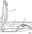
- Fig. 2 denotes a component which is pivotally received at one of its ends via a rotary joint 2.
- the swiveling component 1 is part of a frame construction 50 of an in Fig. 1 illustrated seat cushion 106 a rear seat 110, which can be pivoted back and forth between at least two adjustment positions if necessary.
- FIG. 3 an enlarged view of the first embodiment of a rotary joint 2 shown in section is shown.
- the rotary joint 2 is formed at least from a first, outer bearing part 3 and a second, inner bearing part 4.
- the first bearing part 3 has two bearing shells 5, 6, which are coupled together on one side by means of a hinge-like connecting portion 7 and are equipped on the opposite side with two support legs 8, 9, which are interconnected via a screw, not shown. With the help of the support legs 8, 9, the half-shells 5, 6 contracted and the contact pressure of the bearing parts are increased to each other.
- a sleeve part 10 for increasing the contact force between the bearing parts 3, 4 of two preformed sleeve halves 11, 12 is arranged.
- the sleeve halves 11, 12 are connected to each other via a film hinge 13 and have on their opposite longitudinal sides two holding legs 14, 14 ', which are clamped between the support legs 8, 9 of the first bearing part 3.
- the sleeve member 10 is rotatably held between the bearing shells 5, 6 and in particular forms the sliding surface 15 for the sliding surface 16 of the second bearing part 4.
- a material thickening or bulging formed as an inhibiting part 17 is furthermore provided, which corresponds to a respective, groove-like depression 18, 19 on the outer lateral surface of the second bearing part 4.
- Fig. 4 is a sectional view of the rotary joint 2 shown parallel to the axis of rotation, which further illustrates the structure of the rotary joint 2.
- the inhibiting part 17 extends over a predetermined portion parallel to the longitudinal axis of the sleeve part 10, whereby always an advantageously secure locking of the second bearing part 4 and thus of the pivotable component 1 is ensured in a respective adjustment position.
- a predetermined adjusting force is necessary, wherein the inhibiting member 17 is then moved out of the recess 18 and at the same time by the original dimensions of the bearing part 4 having sliding surface portion 16 '( Fig. 3 ) is compressed or compressed until the component 1 is adjusted so far that the inhibitor 17 can escape again in the other recess 19.
- a further alternative embodiment of a rotary joint 20 according to the invention is shown, which also has two rotatably held to each other bearing parts 21, 22.
- the bearing part 21 in turn has two bearing shells 23, 24, which are similar to the first embodiment on one side via a hinge-like connection portion 25 and at the opposite end by means of two support legs 26, 27 which are interconnected via screw not shown, be kept at a predetermined distance from each other.
- a sleeve part 28 is provided on the inside of the bearing shells 23, 24, in turn.
- the sleeve member 28 may be similar to that in FIG Fig. 3 and Fig.
- the inhibiting part 32 is arranged protruding outwardly directly on the outer circumferential surface of the bearing part 22, wherein the inhibiting part 32 projects into an opening 33 on the bearing shell 23.
- the breakthrough 33 is provided in particular with a counterpart 34 to be crossed by the arresting part 32, which subdivides the breakthrough into at least two regions assigned to the adjustment positions.
- Counterpart 34 arrests the restraining member 32 up to an example presettable maximum force in the adjustment position. If the force acting on the rotatable bearing part and thus on the inhibiting part rises above this corresponding maximum value, rotation within the rotary joint 20 is initiated and the rotatable bearing part 22 is rotated into the other adjustment position.
Landscapes
- Engineering & Computer Science (AREA)
- Aviation & Aerospace Engineering (AREA)
- Transportation (AREA)
- Mechanical Engineering (AREA)
- Pivots And Pivotal Connections (AREA)
- Seats For Vehicles (AREA)
Claims (10)
- Joint articulé pour un élément maintenu de façon mobile, en particulier pour un coussin de siège d'un siège de véhicule, avec au moins deux éléments de palier maintenus mobiles en rotation l'un par rapport à l'autre, lesquels présentent des surfaces de glissement se faisant face,
caractérisé en ce que
un premier élément de palier (3, 21) présente au moins deux coussinets de palier (5, 6, 23, 24) variables l'un par rapport à l'autre concernant la distance, à l'aide desquels le deuxième élément de palier (4, 22) est entouré au moins en partie sur sa périphérie, et en ce que l'on associe à au moins l'un des éléments de palier (3, 4, 21, 22) au moins un moyen pour l'augmentation de la force de serrage entre les surfaces de glissement (15, 16, 30, 31) des coussinets de palier (5, 6, 23, 24) et du deuxième élément de palier (4, 22). - Joint articulé selon la revendication 1, caractérisé en ce qu'au moins des parties de surface de l'une des surfaces de glissement (15, 16, 30, 31) du premier ou deuxième élément de palier (3, 4, 21, 22) sont réalisées en un élément de manchon (10, 28) séparé avec un diamètre intérieur et extérieur adapté aux dimensions des éléments de palier (3, 4, 21, 22).
- Joint articulé selon la revendication 2, caractérisé en ce que l'élément de manchon (10) est formé par deux moitiés de manchon (11, 12) préformées.
- Joint articulé selon la revendication 3, caractérisé en ce que les moitiés de manchon (11, 12) sont reliées ensemble via une zone de liaison semblable à une charnière.
- Joint articulé selon l'une des revendications 2 à 4,
caractérisé en ce que la matière première pour l'élément de manchon (10, 28) est formée par un matériau présentant des propriétés élastiques. - Joint articulé selon l'une des revendications 1 à 5,
caractérisé en ce que, au niveau de l'une des surfaces de glissement (15, 16, 30, 31) du premier ou deuxième élément de palier (3, 4, 21, 22), un élément de blocage (17, 32) est réalisé en saillie, lequel est en butée avec des zones de surface de la surface de glissement (15, 16, 30, 31) de l'autre élément de palier (3, 4, 21, 22) respectif. - Joint articulé selon la revendication 6, caractérisé en ce que l'élément de blocage (17) est réalisé au niveau de la surface d'enveloppe interne du premier élément de palier (3), lequel correspond par conjugaison de formes à au moins un creux (18, 19) semblable à une moulure sur la surface d'enveloppe externe du deuxième élément de palier (4) dans des positions de réglage définies.
- Joint articulé selon la revendication 6, caractérisé en ce que l'élément de blocage (32) est réalisé sur la surface d'enveloppe externe du deuxième élément de palier (22), dans lequel l'élément de blocage (32) est en saillie au moins dans une percée (33) au niveau de l'un des coussinets de palier (23, 24), dans lequel la percée (33) est subdivisée en zones déterminant des positions de réglage définies par au moins une contrepartie (34) par laquelle l'élément de blocage (32) doit passer.
- Joint articulé selon l'une des revendications 1 à 8,
caractérisé en ce que le premier élément de palier (3, 21) est une douille de logement en deux parties et en ce que le deuxième élément de palier (4, 22) est réalisé en tant que corps tubulaire maintenu de façon rotative dans la douille de logement. - Siège, en particulier siège de véhicule, avec au moins une partie d'assise, telle un coussin de siège ou similaire, lequel est maintenu de façon mobile en pivotement à l'aide d'au moins un joint articulé,
caractérisé en ce que
le joint articulé (2, 20) est un joint articulé selon l'une des revendications 1 à 9.
Applications Claiming Priority (2)
| Application Number | Priority Date | Filing Date | Title |
|---|---|---|---|
| DE102011011480A DE102011011480B4 (de) | 2011-02-17 | 2011-02-17 | Drehgelenk für insbesondere einen Fahrzeugsitz |
| PCT/EP2012/000621 WO2012110220A1 (fr) | 2011-02-17 | 2012-02-13 | Joint articulé destiné en particulier à un siège de véhicule |
Publications (3)
| Publication Number | Publication Date |
|---|---|
| EP2675655A1 EP2675655A1 (fr) | 2013-12-25 |
| EP2675655B1 true EP2675655B1 (fr) | 2017-05-24 |
| EP2675655B8 EP2675655B8 (fr) | 2017-08-23 |
Family
ID=45722574
Family Applications (1)
| Application Number | Title | Priority Date | Filing Date |
|---|---|---|---|
| EP12705054.0A Not-in-force EP2675655B8 (fr) | 2011-02-17 | 2012-02-13 | Joint articulé destiné en particulier à un siège de véhicule |
Country Status (7)
| Country | Link |
|---|---|
| US (1) | US9393884B2 (fr) |
| EP (1) | EP2675655B8 (fr) |
| JP (1) | JP5707516B2 (fr) |
| KR (1) | KR101621924B1 (fr) |
| CN (1) | CN103442938B (fr) |
| DE (1) | DE102011011480B4 (fr) |
| WO (1) | WO2012110220A1 (fr) |
Families Citing this family (1)
| Publication number | Priority date | Publication date | Assignee | Title |
|---|---|---|---|---|
| US12542154B2 (en) | 2024-07-25 | 2026-02-03 | Western Digital Technologies, Inc. | Sealed hard disk drive base insert |
Family Cites Families (19)
| Publication number | Priority date | Publication date | Assignee | Title |
|---|---|---|---|---|
| DE214605C (fr) * | ||||
| US2939740A (en) * | 1957-06-13 | 1960-06-07 | Ford Motor Co | Vehicle seat construction |
| FR1593756A (fr) * | 1968-11-28 | 1970-06-01 | ||
| JPH0444131Y2 (fr) * | 1987-07-24 | 1992-10-19 | ||
| JP3133796B2 (ja) * | 1991-09-10 | 2001-02-13 | マツダ株式会社 | 自動車のシート装置 |
| JPH0633544U (ja) * | 1992-04-30 | 1994-05-06 | 株式会社アイテス | ヘッドレストの前後位置調節装置 |
| JPH09175238A (ja) * | 1995-12-22 | 1997-07-08 | Toyota Autom Loom Works Ltd | シートクッションの取付構造 |
| DE29609018U1 (de) * | 1996-05-20 | 1996-08-14 | Chang, Jung Pin, Taichung | Schnellklemmvorrichtung für eine Universalverbindung |
| DE19731305C2 (de) * | 1997-07-14 | 2002-02-14 | Brose Fahrzeugteile | Gelenkverbindung |
| WO1999059836A1 (fr) * | 1998-05-15 | 1999-11-25 | Magna Interior Systems Inc. | Ensemble support de siege a pliage et culbute |
| US6514146B1 (en) * | 2002-02-26 | 2003-02-04 | Kinzou Shinozuka | Low vibration shielded bellows shaft coupling |
| DE10241737B4 (de) * | 2002-09-10 | 2005-09-22 | Schefenacker Vision Systems Germany Gmbh & Co. Kg | Rastgesperre für eine Fahrzeugaußenspiegelschwenklagerung |
| DE10249100A1 (de) * | 2002-10-21 | 2004-05-06 | Johnson Controls Gmbh | Bewegungsbegrenzer, insbesondere für schwenkbare Elemente eines Fahrzeugsitzes |
| DE10305177B4 (de) * | 2003-02-08 | 2008-01-31 | Keiper Gmbh & Co.Kg | Verriegelungsvorrichtung für einen Fahrzeugsitz |
| DE102004017099A1 (de) * | 2004-04-07 | 2005-11-10 | Oris Fahrzeugteile Hans Riehle Gmbh | Anordnung von Bauteilen, die relativ zueinander beweglich sind und in mindestens zwei Positionen mittels einer Rastvorrichtung eine definierte stabile Lage einnehmen |
| FR2897311B1 (fr) * | 2006-02-14 | 2009-01-23 | Plasthom S A Sa | Dispositif de verrouillage, notamment d'un siege de vehicule automobile sur son plancher interieur |
| US7775596B2 (en) * | 2006-12-04 | 2010-08-17 | Lear Corporation | Smartfold electronic actuation |
| DE102007002366B3 (de) * | 2007-01-13 | 2008-07-17 | Keiper Gmbh & Co.Kg | Beschlagsystem für einen Fahrzeugsitz |
| CN101451574B (zh) * | 2007-12-07 | 2012-03-28 | 鸿富锦精密工业(深圳)有限公司 | 转动制动结构 |
-
2011
- 2011-02-17 DE DE102011011480A patent/DE102011011480B4/de not_active Expired - Fee Related
-
2012
- 2012-02-13 JP JP2013553833A patent/JP5707516B2/ja not_active Expired - Fee Related
- 2012-02-13 WO PCT/EP2012/000621 patent/WO2012110220A1/fr not_active Ceased
- 2012-02-13 EP EP12705054.0A patent/EP2675655B8/fr not_active Not-in-force
- 2012-02-13 CN CN201280014828.1A patent/CN103442938B/zh not_active Expired - Fee Related
- 2012-02-13 KR KR1020137024581A patent/KR101621924B1/ko not_active Expired - Fee Related
-
2013
- 2013-08-16 US US13/969,460 patent/US9393884B2/en not_active Expired - Fee Related
Also Published As
| Publication number | Publication date |
|---|---|
| EP2675655B8 (fr) | 2017-08-23 |
| CN103442938B (zh) | 2017-02-15 |
| CN103442938A (zh) | 2013-12-11 |
| WO2012110220A1 (fr) | 2012-08-23 |
| JP2014511298A (ja) | 2014-05-15 |
| DE102011011480B4 (de) | 2013-02-07 |
| KR20130114748A (ko) | 2013-10-17 |
| JP5707516B2 (ja) | 2015-04-30 |
| KR101621924B1 (ko) | 2016-05-17 |
| US20130334859A1 (en) | 2013-12-19 |
| US9393884B2 (en) | 2016-07-19 |
| EP2675655A1 (fr) | 2013-12-25 |
| DE102011011480A1 (de) | 2012-08-23 |
Similar Documents
| Publication | Publication Date | Title |
|---|---|---|
| DE102013107728B4 (de) | Klemmvorrichtung für eine längsverstellbare und/oder höhenverstellbare Lenksäule eines Fahrzeugs | |
| DE2656799C2 (de) | Verfahren zum Herstellen eines elastisch nachgiebigen Bauteiles sowie Verwendung der verfahrensgemäß hergestellten Bauteils als elastisches Schwenklager für einen Querlenker einer Fahrzeugachse | |
| EP3409144B1 (fr) | Chaise, notamment chaise de conférence ou de bureau ainsi que procédé de fabrication d'une chaise | |
| DE102018218499B4 (de) | Außenrückspiegelanordnung mit einstellbarer Spaltdichtung | |
| DE102011106285A1 (de) | Beschlagsystem für einen Fahrzeugsitz | |
| EP2758619A1 (fr) | Dispositif de synchronisation pour déplacer des parties de meuble | |
| EP3233567B1 (fr) | Appuie-tête et procédé de montage d'une appuie-tête | |
| DE4227871A1 (de) | Schwenkbares Funktionsteil als Ausstattung eines Kraftfahrzeuges | |
| EP2998072B1 (fr) | Tendeur de jambe de force à ressort destiné au changement d'un ressort ou d'un amortisseur d'une jambe de force à ressort d'un véhicule automobile | |
| DE10118301A1 (de) | Kraftwagentürscharnier | |
| DE102011018895B4 (de) | Rückenlehne mit einer Dämpfungsvorrichtung | |
| DE102019118258A1 (de) | Fahrzeugsitz-Strukturbauteil und Fahrzeugsitz | |
| EP2675655B1 (fr) | Joint articulé destiné en particulier à un siège de véhicule | |
| DE102010020570B4 (de) | Fahrzeugsitz mit einer verschwenkbaren Rückenlehne sowie Schwenklagerung einer umklappbaren Rückenlehne eines Fahrzeugsitzes | |
| EP2423532B1 (fr) | Douille en caoutchouc d'acier | |
| DE102008006102B4 (de) | Behälter zum Einbau in den Innenraum eines Kraftfahrzeuges | |
| DE102004035817B4 (de) | Bremssystem eines ersten Elements bezüglich eines zweiten Elements und Fahrzeugsitz umfassend ein solches Bremssystem | |
| DE4403506A1 (de) | Fahrzeugsitz | |
| DE10134355A1 (de) | Verstellbeschlag für Kraftfahrzeugsitze | |
| EP2946969B1 (fr) | Repose-tête pour un siège de véhicule | |
| DE102012221645A1 (de) | Federsystem für eine schwenkbare, in einer Schließlage verriegelbare Klappe, insbesondere eines Kraftfahrzeugs | |
| DE4419407C2 (de) | Armlehne für Fahrzeugsitze | |
| DE3717094A1 (de) | Sonnenblende fuer fahrzeuge | |
| EP2077199B1 (fr) | Dispositif pare-vent doté d'un joint double synchronisé | |
| EP4050186B1 (fr) | Dispositif d'articulation pour une unité de volet d'un véhicule automobile, ainsi qu'unité de volet pour un véhicule automobile |
Legal Events
| Date | Code | Title | Description |
|---|---|---|---|
| PUAI | Public reference made under article 153(3) epc to a published international application that has entered the european phase |
Free format text: ORIGINAL CODE: 0009012 |
|
| 17P | Request for examination filed |
Effective date: 20130917 |
|
| AK | Designated contracting states |
Kind code of ref document: A1 Designated state(s): AL AT BE BG CH CY CZ DE DK EE ES FI FR GB GR HR HU IE IS IT LI LT LU LV MC MK MT NL NO PL PT RO RS SE SI SK SM TR |
|
| DAX | Request for extension of the european patent (deleted) | ||
| REG | Reference to a national code |
Ref country code: DE Ref legal event code: R079 Ref document number: 502012010406 Country of ref document: DE Free format text: PREVIOUS MAIN CLASS: B60N0002015000 Ipc: B60N0002200000 |
|
| RIC1 | Information provided on ipc code assigned before grant |
Ipc: B60N 2/20 20060101AFI20161031BHEP Ipc: B60N 2/30 20060101ALI20161031BHEP Ipc: B60N 2/015 20060101ALI20161031BHEP Ipc: B60N 2/36 20060101ALI20161031BHEP Ipc: B60N 2/68 20060101ALI20161031BHEP |
|
| GRAP | Despatch of communication of intention to grant a patent |
Free format text: ORIGINAL CODE: EPIDOSNIGR1 |
|
| INTG | Intention to grant announced |
Effective date: 20161209 |
|
| GRAS | Grant fee paid |
Free format text: ORIGINAL CODE: EPIDOSNIGR3 |
|
| GRAA | (expected) grant |
Free format text: ORIGINAL CODE: 0009210 |
|
| AK | Designated contracting states |
Kind code of ref document: B1 Designated state(s): AL AT BE BG CH CY CZ DE DK EE ES FI FR GB GR HR HU IE IS IT LI LT LU LV MC MK MT NL NO PL PT RO RS SE SI SK SM TR |
|
| REG | Reference to a national code |
Ref country code: GB Ref legal event code: FG4D Free format text: NOT ENGLISH |
|
| REG | Reference to a national code |
Ref country code: CH Ref legal event code: EP |
|
| REG | Reference to a national code |
Ref country code: IE Ref legal event code: FG4D Free format text: LANGUAGE OF EP DOCUMENT: GERMAN |
|
| REG | Reference to a national code |
Ref country code: AT Ref legal event code: REF Ref document number: 895851 Country of ref document: AT Kind code of ref document: T Effective date: 20170615 |
|
| REG | Reference to a national code |
Ref country code: DE Ref legal event code: R081 Ref document number: 502012010406 Country of ref document: DE Owner name: ADIENT US LLC, PLYMOUTH, US Free format text: FORMER OWNER: JOHNSON CONTROLS GMBH, 51399 BURSCHEID, DE Ref country code: DE Ref legal event code: R081 Ref document number: 502012010406 Country of ref document: DE Owner name: ADIENT LUXEMBOURG HOLDING S.A R.L., LU Free format text: FORMER OWNER: JOHNSON CONTROLS GMBH, 51399 BURSCHEID, DE |
|
| RAP2 | Party data changed (patent owner data changed or rights of a patent transferred) |
Owner name: ADIENT LUXEMBOURG HOLDING S.A R.L. |
|
| REG | Reference to a national code |
Ref country code: DE Ref legal event code: R096 Ref document number: 502012010406 Country of ref document: DE |
|
| REG | Reference to a national code |
Ref country code: NL Ref legal event code: MP Effective date: 20170524 |
|
| REG | Reference to a national code |
Ref country code: LT Ref legal event code: MG4D |
|
| PG25 | Lapsed in a contracting state [announced via postgrant information from national office to epo] |
Ref country code: FI Free format text: LAPSE BECAUSE OF FAILURE TO SUBMIT A TRANSLATION OF THE DESCRIPTION OR TO PAY THE FEE WITHIN THE PRESCRIBED TIME-LIMIT Effective date: 20170524 Ref country code: ES Free format text: LAPSE BECAUSE OF FAILURE TO SUBMIT A TRANSLATION OF THE DESCRIPTION OR TO PAY THE FEE WITHIN THE PRESCRIBED TIME-LIMIT Effective date: 20170524 Ref country code: HR Free format text: LAPSE BECAUSE OF FAILURE TO SUBMIT A TRANSLATION OF THE DESCRIPTION OR TO PAY THE FEE WITHIN THE PRESCRIBED TIME-LIMIT Effective date: 20170524 Ref country code: LT Free format text: LAPSE BECAUSE OF FAILURE TO SUBMIT A TRANSLATION OF THE DESCRIPTION OR TO PAY THE FEE WITHIN THE PRESCRIBED TIME-LIMIT Effective date: 20170524 Ref country code: NO Free format text: LAPSE BECAUSE OF FAILURE TO SUBMIT A TRANSLATION OF THE DESCRIPTION OR TO PAY THE FEE WITHIN THE PRESCRIBED TIME-LIMIT Effective date: 20170824 Ref country code: GR Free format text: LAPSE BECAUSE OF FAILURE TO SUBMIT A TRANSLATION OF THE DESCRIPTION OR TO PAY THE FEE WITHIN THE PRESCRIBED TIME-LIMIT Effective date: 20170825 |
|
| PG25 | Lapsed in a contracting state [announced via postgrant information from national office to epo] |
Ref country code: BG Free format text: LAPSE BECAUSE OF FAILURE TO SUBMIT A TRANSLATION OF THE DESCRIPTION OR TO PAY THE FEE WITHIN THE PRESCRIBED TIME-LIMIT Effective date: 20170824 Ref country code: LV Free format text: LAPSE BECAUSE OF FAILURE TO SUBMIT A TRANSLATION OF THE DESCRIPTION OR TO PAY THE FEE WITHIN THE PRESCRIBED TIME-LIMIT Effective date: 20170524 Ref country code: NL Free format text: LAPSE BECAUSE OF FAILURE TO SUBMIT A TRANSLATION OF THE DESCRIPTION OR TO PAY THE FEE WITHIN THE PRESCRIBED TIME-LIMIT Effective date: 20170524 Ref country code: IS Free format text: LAPSE BECAUSE OF FAILURE TO SUBMIT A TRANSLATION OF THE DESCRIPTION OR TO PAY THE FEE WITHIN THE PRESCRIBED TIME-LIMIT Effective date: 20170924 Ref country code: SE Free format text: LAPSE BECAUSE OF FAILURE TO SUBMIT A TRANSLATION OF THE DESCRIPTION OR TO PAY THE FEE WITHIN THE PRESCRIBED TIME-LIMIT Effective date: 20170524 Ref country code: RS Free format text: LAPSE BECAUSE OF FAILURE TO SUBMIT A TRANSLATION OF THE DESCRIPTION OR TO PAY THE FEE WITHIN THE PRESCRIBED TIME-LIMIT Effective date: 20170524 |
|
| PG25 | Lapsed in a contracting state [announced via postgrant information from national office to epo] |
Ref country code: CZ Free format text: LAPSE BECAUSE OF FAILURE TO SUBMIT A TRANSLATION OF THE DESCRIPTION OR TO PAY THE FEE WITHIN THE PRESCRIBED TIME-LIMIT Effective date: 20170524 Ref country code: SK Free format text: LAPSE BECAUSE OF FAILURE TO SUBMIT A TRANSLATION OF THE DESCRIPTION OR TO PAY THE FEE WITHIN THE PRESCRIBED TIME-LIMIT Effective date: 20170524 Ref country code: EE Free format text: LAPSE BECAUSE OF FAILURE TO SUBMIT A TRANSLATION OF THE DESCRIPTION OR TO PAY THE FEE WITHIN THE PRESCRIBED TIME-LIMIT Effective date: 20170524 Ref country code: DK Free format text: LAPSE BECAUSE OF FAILURE TO SUBMIT A TRANSLATION OF THE DESCRIPTION OR TO PAY THE FEE WITHIN THE PRESCRIBED TIME-LIMIT Effective date: 20170524 Ref country code: RO Free format text: LAPSE BECAUSE OF FAILURE TO SUBMIT A TRANSLATION OF THE DESCRIPTION OR TO PAY THE FEE WITHIN THE PRESCRIBED TIME-LIMIT Effective date: 20170524 |
|
| REG | Reference to a national code |
Ref country code: FR Ref legal event code: PLFP Year of fee payment: 7 |
|
| REG | Reference to a national code |
Ref country code: DE Ref legal event code: R097 Ref document number: 502012010406 Country of ref document: DE |
|
| PG25 | Lapsed in a contracting state [announced via postgrant information from national office to epo] |
Ref country code: IT Free format text: LAPSE BECAUSE OF FAILURE TO SUBMIT A TRANSLATION OF THE DESCRIPTION OR TO PAY THE FEE WITHIN THE PRESCRIBED TIME-LIMIT Effective date: 20170524 Ref country code: SM Free format text: LAPSE BECAUSE OF FAILURE TO SUBMIT A TRANSLATION OF THE DESCRIPTION OR TO PAY THE FEE WITHIN THE PRESCRIBED TIME-LIMIT Effective date: 20170524 Ref country code: PL Free format text: LAPSE BECAUSE OF FAILURE TO SUBMIT A TRANSLATION OF THE DESCRIPTION OR TO PAY THE FEE WITHIN THE PRESCRIBED TIME-LIMIT Effective date: 20170524 |
|
| REG | Reference to a national code |
Ref country code: DE Ref legal event code: R081 Ref document number: 502012010406 Country of ref document: DE Owner name: ADIENT US LLC, PLYMOUTH, US Free format text: FORMER OWNER: ADIENT LUXEMBOURG HOLDING S.A.R.L., LUXEMBOURG, LU Ref country code: DE Ref legal event code: R081 Ref document number: 502012010406 Country of ref document: DE Owner name: ADIENT LUXEMBOURG HOLDING S.A R.L., LU Free format text: FORMER OWNER: ADIENT LUXEMBOURG HOLDING S.A.R.L., LUXEMBOURG, LU |
|
| RAP2 | Party data changed (patent owner data changed or rights of a patent transferred) |
Owner name: ADIENT LUXEMBOURG HOLDING S.A R.L. |
|
| PLBE | No opposition filed within time limit |
Free format text: ORIGINAL CODE: 0009261 |
|
| STAA | Information on the status of an ep patent application or granted ep patent |
Free format text: STATUS: NO OPPOSITION FILED WITHIN TIME LIMIT |
|
| 26N | No opposition filed |
Effective date: 20180227 |
|
| PG25 | Lapsed in a contracting state [announced via postgrant information from national office to epo] |
Ref country code: SI Free format text: LAPSE BECAUSE OF FAILURE TO SUBMIT A TRANSLATION OF THE DESCRIPTION OR TO PAY THE FEE WITHIN THE PRESCRIBED TIME-LIMIT Effective date: 20170524 |
|
| REG | Reference to a national code |
Ref country code: CH Ref legal event code: PL |
|
| PG25 | Lapsed in a contracting state [announced via postgrant information from national office to epo] |
Ref country code: MT Free format text: LAPSE BECAUSE OF FAILURE TO SUBMIT A TRANSLATION OF THE DESCRIPTION OR TO PAY THE FEE WITHIN THE PRESCRIBED TIME-LIMIT Effective date: 20170524 Ref country code: MC Free format text: LAPSE BECAUSE OF FAILURE TO SUBMIT A TRANSLATION OF THE DESCRIPTION OR TO PAY THE FEE WITHIN THE PRESCRIBED TIME-LIMIT Effective date: 20170524 |
|
| GBPC | Gb: european patent ceased through non-payment of renewal fee |
Effective date: 20180213 |
|
| REG | Reference to a national code |
Ref country code: IE Ref legal event code: MM4A |
|
| REG | Reference to a national code |
Ref country code: BE Ref legal event code: MM Effective date: 20180228 |
|
| PG25 | Lapsed in a contracting state [announced via postgrant information from national office to epo] |
Ref country code: CH Free format text: LAPSE BECAUSE OF NON-PAYMENT OF DUE FEES Effective date: 20180228 Ref country code: LU Free format text: LAPSE BECAUSE OF NON-PAYMENT OF DUE FEES Effective date: 20180213 Ref country code: LI Free format text: LAPSE BECAUSE OF NON-PAYMENT OF DUE FEES Effective date: 20180228 |
|
| PG25 | Lapsed in a contracting state [announced via postgrant information from national office to epo] |
Ref country code: IE Free format text: LAPSE BECAUSE OF NON-PAYMENT OF DUE FEES Effective date: 20180213 |
|
| PG25 | Lapsed in a contracting state [announced via postgrant information from national office to epo] |
Ref country code: GB Free format text: LAPSE BECAUSE OF NON-PAYMENT OF DUE FEES Effective date: 20180213 Ref country code: BE Free format text: LAPSE BECAUSE OF NON-PAYMENT OF DUE FEES Effective date: 20180228 |
|
| REG | Reference to a national code |
Ref country code: AT Ref legal event code: MM01 Ref document number: 895851 Country of ref document: AT Kind code of ref document: T Effective date: 20180213 |
|
| PG25 | Lapsed in a contracting state [announced via postgrant information from national office to epo] |
Ref country code: AT Free format text: LAPSE BECAUSE OF NON-PAYMENT OF DUE FEES Effective date: 20180213 |
|
| PG25 | Lapsed in a contracting state [announced via postgrant information from national office to epo] |
Ref country code: TR Free format text: LAPSE BECAUSE OF FAILURE TO SUBMIT A TRANSLATION OF THE DESCRIPTION OR TO PAY THE FEE WITHIN THE PRESCRIBED TIME-LIMIT Effective date: 20170524 |
|
| PG25 | Lapsed in a contracting state [announced via postgrant information from national office to epo] |
Ref country code: PT Free format text: LAPSE BECAUSE OF FAILURE TO SUBMIT A TRANSLATION OF THE DESCRIPTION OR TO PAY THE FEE WITHIN THE PRESCRIBED TIME-LIMIT Effective date: 20170524 Ref country code: HU Free format text: LAPSE BECAUSE OF FAILURE TO SUBMIT A TRANSLATION OF THE DESCRIPTION OR TO PAY THE FEE WITHIN THE PRESCRIBED TIME-LIMIT; INVALID AB INITIO Effective date: 20120213 |
|
| PG25 | Lapsed in a contracting state [announced via postgrant information from national office to epo] |
Ref country code: CY Free format text: LAPSE BECAUSE OF FAILURE TO SUBMIT A TRANSLATION OF THE DESCRIPTION OR TO PAY THE FEE WITHIN THE PRESCRIBED TIME-LIMIT Effective date: 20170524 Ref country code: MK Free format text: LAPSE BECAUSE OF NON-PAYMENT OF DUE FEES Effective date: 20170524 |
|
| PG25 | Lapsed in a contracting state [announced via postgrant information from national office to epo] |
Ref country code: AL Free format text: LAPSE BECAUSE OF FAILURE TO SUBMIT A TRANSLATION OF THE DESCRIPTION OR TO PAY THE FEE WITHIN THE PRESCRIBED TIME-LIMIT Effective date: 20170524 |
|
| REG | Reference to a national code |
Ref country code: DE Ref legal event code: R082 Ref document number: 502012010406 Country of ref document: DE Representative=s name: LIEDHEGENER, RALF, DIPL.-ING., DE |
|
| PGFP | Annual fee paid to national office [announced via postgrant information from national office to epo] |
Ref country code: DE Payment date: 20220225 Year of fee payment: 11 |
|
| PGFP | Annual fee paid to national office [announced via postgrant information from national office to epo] |
Ref country code: FR Payment date: 20220223 Year of fee payment: 11 |
|
| REG | Reference to a national code |
Ref country code: DE Ref legal event code: R081 Ref document number: 502012010406 Country of ref document: DE Owner name: ADIENT US LLC, PLYMOUTH, US Free format text: FORMER OWNER: ADIENT LUXEMBOURG HOLDING S.A R.L., LUXEMBOURG, LU |
|
| REG | Reference to a national code |
Ref country code: DE Ref legal event code: R119 Ref document number: 502012010406 Country of ref document: DE |
|
| PG25 | Lapsed in a contracting state [announced via postgrant information from national office to epo] |
Ref country code: FR Free format text: LAPSE BECAUSE OF NON-PAYMENT OF DUE FEES Effective date: 20230228 Ref country code: DE Free format text: LAPSE BECAUSE OF NON-PAYMENT OF DUE FEES Effective date: 20230901 |