EP2676016B2 - Ensemble de post-traitement des gaz d'echappement d'un moteur a combustion suralimente, et vehicule automobile comportant un tel ensemble - Google Patents
Ensemble de post-traitement des gaz d'echappement d'un moteur a combustion suralimente, et vehicule automobile comportant un tel ensemble Download PDFInfo
- Publication number
- EP2676016B2 EP2676016B2 EP12705320.5A EP12705320A EP2676016B2 EP 2676016 B2 EP2676016 B2 EP 2676016B2 EP 12705320 A EP12705320 A EP 12705320A EP 2676016 B2 EP2676016 B2 EP 2676016B2
- Authority
- EP
- European Patent Office
- Prior art keywords
- assembly according
- branch
- catalyst
- nitrogen oxides
- selective catalytic
- Prior art date
- Legal status (The legal status is an assumption and is not a legal conclusion. Google has not performed a legal analysis and makes no representation as to the accuracy of the status listed.)
- Active
Links
Images



Classifications
-
- F—MECHANICAL ENGINEERING; LIGHTING; HEATING; WEAPONS; BLASTING
- F01—MACHINES OR ENGINES IN GENERAL; ENGINE PLANTS IN GENERAL; STEAM ENGINES
- F01N—GAS-FLOW SILENCERS OR EXHAUST APPARATUS FOR MACHINES OR ENGINES IN GENERAL; GAS-FLOW SILENCERS OR EXHAUST APPARATUS FOR INTERNAL-COMBUSTION ENGINES
- F01N3/00—Exhaust or silencing apparatus having means for purifying, rendering innocuous, or otherwise treating exhaust
- F01N3/02—Exhaust or silencing apparatus having means for purifying, rendering innocuous, or otherwise treating exhaust for cooling, or for removing solid constituents of, exhaust
- F01N3/021—Exhaust or silencing apparatus having means for purifying, rendering innocuous, or otherwise treating exhaust for cooling, or for removing solid constituents of, exhaust by means of filters
- F01N3/033—Exhaust or silencing apparatus having means for purifying, rendering innocuous, or otherwise treating exhaust for cooling, or for removing solid constituents of, exhaust by means of filters in combination with other devices
- F01N3/035—Exhaust or silencing apparatus having means for purifying, rendering innocuous, or otherwise treating exhaust for cooling, or for removing solid constituents of, exhaust by means of filters in combination with other devices with catalytic reactors
-
- F—MECHANICAL ENGINEERING; LIGHTING; HEATING; WEAPONS; BLASTING
- F01—MACHINES OR ENGINES IN GENERAL; ENGINE PLANTS IN GENERAL; STEAM ENGINES
- F01N—GAS-FLOW SILENCERS OR EXHAUST APPARATUS FOR MACHINES OR ENGINES IN GENERAL; GAS-FLOW SILENCERS OR EXHAUST APPARATUS FOR INTERNAL-COMBUSTION ENGINES
- F01N13/00—Exhaust or silencing apparatus characterised by constructional features
- F01N13/009—Exhaust or silencing apparatus characterised by constructional features having two or more separate purifying devices arranged in series
-
- F—MECHANICAL ENGINEERING; LIGHTING; HEATING; WEAPONS; BLASTING
- F01—MACHINES OR ENGINES IN GENERAL; ENGINE PLANTS IN GENERAL; STEAM ENGINES
- F01N—GAS-FLOW SILENCERS OR EXHAUST APPARATUS FOR MACHINES OR ENGINES IN GENERAL; GAS-FLOW SILENCERS OR EXHAUST APPARATUS FOR INTERNAL-COMBUSTION ENGINES
- F01N13/00—Exhaust or silencing apparatus characterised by constructional features
- F01N13/009—Exhaust or silencing apparatus characterised by constructional features having two or more separate purifying devices arranged in series
- F01N13/0097—Exhaust or silencing apparatus characterised by constructional features having two or more separate purifying devices arranged in series the purifying devices are arranged in a single housing
-
- F—MECHANICAL ENGINEERING; LIGHTING; HEATING; WEAPONS; BLASTING
- F01—MACHINES OR ENGINES IN GENERAL; ENGINE PLANTS IN GENERAL; STEAM ENGINES
- F01N—GAS-FLOW SILENCERS OR EXHAUST APPARATUS FOR MACHINES OR ENGINES IN GENERAL; GAS-FLOW SILENCERS OR EXHAUST APPARATUS FOR INTERNAL-COMBUSTION ENGINES
- F01N13/00—Exhaust or silencing apparatus characterised by constructional features
- F01N13/08—Other arrangements or adaptations of exhaust conduits
-
- F—MECHANICAL ENGINEERING; LIGHTING; HEATING; WEAPONS; BLASTING
- F01—MACHINES OR ENGINES IN GENERAL; ENGINE PLANTS IN GENERAL; STEAM ENGINES
- F01N—GAS-FLOW SILENCERS OR EXHAUST APPARATUS FOR MACHINES OR ENGINES IN GENERAL; GAS-FLOW SILENCERS OR EXHAUST APPARATUS FOR INTERNAL-COMBUSTION ENGINES
- F01N3/00—Exhaust or silencing apparatus having means for purifying, rendering innocuous, or otherwise treating exhaust
- F01N3/08—Exhaust or silencing apparatus having means for purifying, rendering innocuous, or otherwise treating exhaust for rendering innocuous
- F01N3/10—Exhaust or silencing apparatus having means for purifying, rendering innocuous, or otherwise treating exhaust for rendering innocuous by thermal or catalytic conversion of noxious components of exhaust
- F01N3/18—Exhaust or silencing apparatus having means for purifying, rendering innocuous, or otherwise treating exhaust for rendering innocuous by thermal or catalytic conversion of noxious components of exhaust characterised by methods of operation; Control
- F01N3/20—Exhaust or silencing apparatus having means for purifying, rendering innocuous, or otherwise treating exhaust for rendering innocuous by thermal or catalytic conversion of noxious components of exhaust characterised by methods of operation; Control specially adapted for catalytic conversion
- F01N3/206—Adding periodically or continuously substances to exhaust gases for promoting purification, e.g. catalytic material in liquid form, NOx reducing agents
- F01N3/2066—Selective catalytic reduction [SCR]
-
- F—MECHANICAL ENGINEERING; LIGHTING; HEATING; WEAPONS; BLASTING
- F01—MACHINES OR ENGINES IN GENERAL; ENGINE PLANTS IN GENERAL; STEAM ENGINES
- F01N—GAS-FLOW SILENCERS OR EXHAUST APPARATUS FOR MACHINES OR ENGINES IN GENERAL; GAS-FLOW SILENCERS OR EXHAUST APPARATUS FOR INTERNAL-COMBUSTION ENGINES
- F01N3/00—Exhaust or silencing apparatus having means for purifying, rendering innocuous, or otherwise treating exhaust
- F01N3/08—Exhaust or silencing apparatus having means for purifying, rendering innocuous, or otherwise treating exhaust for rendering innocuous
- F01N3/10—Exhaust or silencing apparatus having means for purifying, rendering innocuous, or otherwise treating exhaust for rendering innocuous by thermal or catalytic conversion of noxious components of exhaust
- F01N3/24—Exhaust or silencing apparatus having means for purifying, rendering innocuous, or otherwise treating exhaust for rendering innocuous by thermal or catalytic conversion of noxious components of exhaust characterised by constructional aspects of converting apparatus
- F01N3/28—Construction of catalytic reactors
- F01N3/2892—Exhaust flow directors or the like, e.g. upstream of catalytic device
-
- F—MECHANICAL ENGINEERING; LIGHTING; HEATING; WEAPONS; BLASTING
- F02—COMBUSTION ENGINES; HOT-GAS OR COMBUSTION-PRODUCT ENGINE PLANTS
- F02B—INTERNAL-COMBUSTION PISTON ENGINES; COMBUSTION ENGINES IN GENERAL
- F02B37/00—Engines characterised by provision of pumps driven at least for part of the time by exhaust
-
- F—MECHANICAL ENGINEERING; LIGHTING; HEATING; WEAPONS; BLASTING
- F01—MACHINES OR ENGINES IN GENERAL; ENGINE PLANTS IN GENERAL; STEAM ENGINES
- F01N—GAS-FLOW SILENCERS OR EXHAUST APPARATUS FOR MACHINES OR ENGINES IN GENERAL; GAS-FLOW SILENCERS OR EXHAUST APPARATUS FOR INTERNAL-COMBUSTION ENGINES
- F01N2340/00—Dimensional characteristics of the exhaust system, e.g. length, diameter or volume of the exhaust apparatus; Spatial arrangements of exhaust apparatuses
- F01N2340/02—Distance of the exhaust apparatus to the engine or between two exhaust apparatuses
-
- F—MECHANICAL ENGINEERING; LIGHTING; HEATING; WEAPONS; BLASTING
- F01—MACHINES OR ENGINES IN GENERAL; ENGINE PLANTS IN GENERAL; STEAM ENGINES
- F01N—GAS-FLOW SILENCERS OR EXHAUST APPARATUS FOR MACHINES OR ENGINES IN GENERAL; GAS-FLOW SILENCERS OR EXHAUST APPARATUS FOR INTERNAL-COMBUSTION ENGINES
- F01N2340/00—Dimensional characteristics of the exhaust system, e.g. length, diameter or volume of the exhaust apparatus; Spatial arrangements of exhaust apparatuses
- F01N2340/04—Arrangement of the exhaust system relative to a vehicle or parts thereof
-
- F—MECHANICAL ENGINEERING; LIGHTING; HEATING; WEAPONS; BLASTING
- F01—MACHINES OR ENGINES IN GENERAL; ENGINE PLANTS IN GENERAL; STEAM ENGINES
- F01N—GAS-FLOW SILENCERS OR EXHAUST APPARATUS FOR MACHINES OR ENGINES IN GENERAL; GAS-FLOW SILENCERS OR EXHAUST APPARATUS FOR INTERNAL-COMBUSTION ENGINES
- F01N2470/00—Structure or shape of exhaust gas passages, pipes or tubes
- F01N2470/18—Structure or shape of exhaust gas passages, pipes or tubes the axis of inlet or outlet tubes being other than the longitudinal axis of apparatus
-
- F—MECHANICAL ENGINEERING; LIGHTING; HEATING; WEAPONS; BLASTING
- F01—MACHINES OR ENGINES IN GENERAL; ENGINE PLANTS IN GENERAL; STEAM ENGINES
- F01N—GAS-FLOW SILENCERS OR EXHAUST APPARATUS FOR MACHINES OR ENGINES IN GENERAL; GAS-FLOW SILENCERS OR EXHAUST APPARATUS FOR INTERNAL-COMBUSTION ENGINES
- F01N3/00—Exhaust or silencing apparatus having means for purifying, rendering innocuous, or otherwise treating exhaust
- F01N3/08—Exhaust or silencing apparatus having means for purifying, rendering innocuous, or otherwise treating exhaust for rendering innocuous
- F01N3/10—Exhaust or silencing apparatus having means for purifying, rendering innocuous, or otherwise treating exhaust for rendering innocuous by thermal or catalytic conversion of noxious components of exhaust
- F01N3/103—Oxidation catalysts for HC and CO only
-
- Y—GENERAL TAGGING OF NEW TECHNOLOGICAL DEVELOPMENTS; GENERAL TAGGING OF CROSS-SECTIONAL TECHNOLOGIES SPANNING OVER SEVERAL SECTIONS OF THE IPC; TECHNICAL SUBJECTS COVERED BY FORMER USPC CROSS-REFERENCE ART COLLECTIONS [XRACs] AND DIGESTS
- Y02—TECHNOLOGIES OR APPLICATIONS FOR MITIGATION OR ADAPTATION AGAINST CLIMATE CHANGE
- Y02A—TECHNOLOGIES FOR ADAPTATION TO CLIMATE CHANGE
- Y02A50/00—TECHNOLOGIES FOR ADAPTATION TO CLIMATE CHANGE in human health protection, e.g. against extreme weather
- Y02A50/20—Air quality improvement or preservation, e.g. vehicle emission control or emission reduction by using catalytic converters
-
- Y—GENERAL TAGGING OF NEW TECHNOLOGICAL DEVELOPMENTS; GENERAL TAGGING OF CROSS-SECTIONAL TECHNOLOGIES SPANNING OVER SEVERAL SECTIONS OF THE IPC; TECHNICAL SUBJECTS COVERED BY FORMER USPC CROSS-REFERENCE ART COLLECTIONS [XRACs] AND DIGESTS
- Y02—TECHNOLOGIES OR APPLICATIONS FOR MITIGATION OR ADAPTATION AGAINST CLIMATE CHANGE
- Y02T—CLIMATE CHANGE MITIGATION TECHNOLOGIES RELATED TO TRANSPORTATION
- Y02T10/00—Road transport of goods or passengers
- Y02T10/10—Internal combustion engine [ICE] based vehicles
- Y02T10/12—Improving ICE efficiencies
Definitions
- the invention relates to the field of means for treating pollutants from exhaust gases of combustion engines.
- Pollutant emissions from combustion engines in motor vehicles are regulated by increasingly stringent standards.
- the regulated pollutants are - depending on the combustion engine technology considered - carbon monoxide (CO), unburned hydrocarbons (HC), nitrogen oxides (NOx), and particles.
- An oxidation catalyst allows the treatment of carbon monoxide, unburned hydrocarbons, and under certain conditions nitrogen oxides; a particulate filter can be used for the treatment of soot particles.
- a specific post-treatment system can be introduced into the exhaust line of vehicles, particularly vehicles equipped with diesel engines.
- SCR selective catalytic reduction
- a reducing agent or a precursor of such a reducing agent
- This may, for example, be a urea solution, the decomposition of which will produce ammonia which will serve as a reducing agent, but also a reducing agent or a precursor of such a reducing agent in gaseous form.
- a "reducer" to designate a reducing agent or a precursor of a reducing agent.
- the reducing agent generated makes it possible to reduce nitrogen oxides by reaction in an SCR catalyst, i.e. a substrate carrying a catalytic impregnation capable of promoting the reduction of NOx by the reducing agent.
- Selective catalytic reduction technologies have the advantage of allowing a very high level of conversion of nitrogen oxides.
- SCR catalysis requires adding a catalytic substrate into the exhaust line, as well as a means of introducing the reductant into the exhaust gases, which can for example be a reductant injector.
- the SCR catalyst is placed under the vehicle body, far from the engine because the injected reducer needs a long path in the exhaust line to decompose on the one hand, and sufficient free volumes to implant itself on the other hand. If the distance traveled by the reducer is not sufficient, the risk of clogging of the exhaust line is significant.
- the SCR catalyst may not be active from the first seconds of vehicle operation, and then allows a significant quantity of untreated nitrogen oxides to pass through.
- the reductant injector which needs to reach a certain temperature level to be operational (sufficient initiation of the decomposition of the urea precursor (adblue) or preheating of the reductant provision system (gas)), suffers from this distance from the exhaust manifold outlet.
- the envelope described in this application is of a relatively short length thanks to the implementation of numerous optimizations described in this patent application.
- the architecture thus proposed may have three drawbacks in particular, depending on the application for which it is intended.
- it is particularly suitable for vertical installation in the under-bonnet space of a combustion engine whose exhaust manifold outlet is located on the front face, i.e. on the side of the front face of the equipped vehicle (if the latter has an under-bonnet space in its front part, which is mainly the case in automotive applications).
- this architecture requires a more or less complex connection to be made with the outlet of a turbocharger, this connection being able to generate thermal losses that are all the more significant the longer it is or the larger the surface area, such as in the case of a connecting elbow.
- the architecture known in the state of the art generally requires a restrictive installation volume in a given direction, that of the “length” of the envelope.
- the particle filter is of the type involving an additive lowering the oxidation temperature of the soot particles.
- additive has the advantage, thanks to its lower soot oxidation temperature compared to a filter without additive (called “catalyzed"), of being able to be installed downstream of an SCR catalyst without its operation being too penalized by the thermal losses linked to its distance from the outlet of the engine.
- the particle filter and the SCR catalyst are made up of a single treatment monolith, the lower temperature level of the filter during its regenerations allows less degradation of the SCR impregnation on the filter.
- connection forms or comprises the mixing means. This makes it possible to obtain a homogeneous mixture between the exhaust gases and the SCR reducer from the inlet of the second branch.
- the mixing means comprise a mixer in the second branch. This allows the use of high-performance mixers, known in the state of the art.
- the oxidation catalyst casing is directly connected to the outlet of the turbocharger turbine. This is the best configuration to avoid any heat loss between these elements.
- the second branch comprises a single envelope grouping the selective catalytic reduction catalyst of nitrogen oxides and the particulate filter. This offers better compactness, reduces the production costs, and avoids any pressure loss between the elements of the second branch.
- the selective catalytic reduction catalyst of nitrogen oxides and the particulate filter are constituted by a single exhaust gas treatment monolith.
- This is a compact and efficient solution to enable complete exhaust gas treatment, which also allows to increase the maximum storage volume of the particulate filter for the same allocation of volume to the two functions of NOx reduction and particulate reduction.
- the second branch has a side-exhaust convergent. This limits the height of the "U”, and favorably directs the exhaust gases in an automotive application.
- the connector forms a third straight branch between the outlet of the first branch and the inlet of the second branch.
- the third branch may be orthogonal to the first and second branches, and have a right-angle bend at each of its ends for its connection to the first and second branches.
- the connector then comprises a junction plate between the first branch and the second branch, a plate surmounted by a hollow cup.
- a junction plate between the first branch and the second branch, a plate surmounted by a hollow cup.
- the U has a width of at most 600 mm, and preferably of the order of 380 mm.
- Such a width, extreme distance between the branches of the “U”, is suitable for automotive use of the invention, for its installation in the under-engine hood area.
- the U has a height of at most 600 mm and preferably of the order of 400 mm.
- a height, extreme distance between the outside of the connector and the end of the longest of the branches of the “U”, is suitable for automotive use of the invention, for its installation in the under-engine hood area.
- the invention also relates to a motor vehicle comprising a combustion engine arranged in an under-hood space, which comprises an assembly according to the invention in said under-hood space.
- the assembly is arranged between a face of the engine and an apron separating the under-hood space from a passenger compartment.
- FIG 1 presents an assembly according to a preferred embodiment of the invention, according to a schematic exterior view in 3 dimensions.
- the figure 2 presents the same embodiment, according to a partial sectional view (the envelopes containing exhaust gas treatment monoliths are schematically represented in section, so as to allow visualization of the different monoliths involved).
- the Figures 3 to 5 similarly present variants of realization.
- An assembly according to the invention comprises a first rectilinear branch 1 and a second rectilinear branch 2.
- the first and second branches are substantially parallel so as to form the two branches of a “U” architecture,
- the first branch comprises a turbocharger 3 and, in a suitable casing or "canning", an oxidation catalyst 4.
- the oxidation catalyst is mainly used for the treatment of unburned hydrocarbons (HC) and carbon monoxide (CO) in a diesel engine.
- the second branch comprises a catalyst for selective catalytic reduction of nitrogen oxides, or SCR catalyst 5.
- the second branch also comprises a particle filter 6.
- the SCR catalyst 5 and the particle filter 6 may, depending on the variant of the invention considered, be contained in a single envelope, or even be grouped into a single monolith called “FAP/SCR” 7, namely a particle filter carrying an impregnation for selective catalytic reduction of nitrogen oxides.
- the particle filter 6 is preferably of a type using an additive to lower the soot oxidation temperature. This feature allows the filter to regenerate at lower temperatures than a so-called “catalyzed” filter (designating a filter not using an additive to lower the soot oxidation temperature).
- the first branch 1 is connected to the second branch by a fluid connection 8 allowing the transport of exhaust gases from the outlet of the first branch to the inlet of the second branch (the concepts of inlet and outlet being understood throughout this document according to the direction of flow of the exhaust gases in the assembly according to the invention).
- SCR catalysis requires the introduction and mixing in the exhaust gases of a reducing agent (reducing agent or precursor of such an agent) by appropriate means such as a dedicated injector (not shown in the figures).
- a reducing agent reducing agent or precursor of such an agent
- the mouth of an introduction means can advantageously be located in the fluid connection 8, preferably towards the inlet of said connection in order to maximize the distance between the point of introduction of the reducing agent and the SCR catalyst 5, such a distance promoting the mixing of the reducing agent in the exhaust gases.
- the shape of the connector 8 can also be optimized so as to promote (or even completely achieve) the homogeneous mixing of the reducer and the exhaust gases.
- a U-shaped configuration as proposed in the invention is also favorable to this phenomenon.
- the connector 8 gives the U-shaped assembly, for an automotive application, a maximum width of 600 mm and can in particular give it a width of around 380 mm.
- the width of the U designates the overall width between the two branches.
- the invention has first and second substantially parallel branches.
- the concept of a “U” shape must be interpreted restrictively, so that a shape substantially closer to a “V” cannot fall within the definition of the invention. The maximum width of the “V” would then be considered.
- the two branches of the U constituted respectively by the first branch 1 and the second branch 2 can of course be connected by a curved or straight connector 8 without departing from the scope of the invention.
- first and second branches can (and generally will) be positioned approximately horizontally.
- the connector 8 is made up of a connecting plate between the first branch 1 and the second branch 2, and of a hollow cup thus forming a hollow body forming a connector.
- the connector 8 may comprise an attached mixer 9, i.e. a device capable of generating turbulence and/or increasing the distance traveled by the exhaust gases so as to promote their homogeneous mixing with the reducing agent, or increase their transport time before reaching the SCR catalyst, for example in order to allow the transformation into a reducing agent of a precursor of such an agent.
- an attached mixer 9 i.e. a device capable of generating turbulence and/or increasing the distance traveled by the exhaust gases so as to promote their homogeneous mixing with the reducing agent, or increase their transport time before reaching the SCR catalyst, for example in order to allow the transformation into a reducing agent of a precursor of such an agent.
- a mixer 9 may, depending on the variant of the invention considered, be arranged in the second branch upstream of the SCR catalyst 5 or the FAP/SCR monolith 7. In this context, it is preferential to use a mixer of the type known from the document FR2947003 . However, and depending on the precise application considered, to the extent that the mixture can be largely engaged in the connection by its geometry alone or by means of other devices, a simpler and less expensive mixer can be used, for example a mixer involving one or more mixing grids, or fins arranged in a staggered pattern.
- the second branch also includes an outlet convergent 10 in order to channel the exhaust gases treated by the assembly according to the invention.
- This convergent preferably has a lateral evacuation. This makes it possible to limit its length and to orient the flow of exhaust gases adequately.
- the first branch 1 and the second branch 2 have substantially equal lengths. This is made possible by the distribution of functions proposed in the invention, namely, the supercharging and catalysis of HC and CO in the first branch 1, the treatment of NOx and particles in the second branch 2. This distribution results in a major advantage in terms of ease of installation of an assembly according to the invention.
- the height of the U i.e. the length of the largest of the branches to which is added the dimension of the connection along the axis of the branch, will preferably be less than 600 mm and may in particular be of the order of 400 mm.
- Figures 8 and 9 thus present a device according to the invention comprising an oval oxidation catalyst and functions for treating NOx and particles by one or more round cylindrical monoliths.
- the connector 8 can be oblique with respect to the two branches, without departing from the scope of the invention, as presented in figure 10 .
- This architecture with oblique 8 connection is compatible with all variants of the invention, for example with round, oval cylindrical treatment monoliths, or with a mixture of round and oval cylindrical monoliths.
- the invention thus developed, by allowing a distribution along two axes of the pollution control elements, promotes the installation of a complete exhaust gas treatment assembly for a combustion engine in a constrained environment where the assembly cannot be installed along a single axis.
- Positioning the oxidation catalyst as close as possible to the turbocharger outlet makes it possible to limit heat losses and to limit thermal inertia opposing the rapid heating of the oxidation catalyst by the exhaust gases (significant thermal inertia is detrimental to catalyst priming, particularly in the context of standardized approval cycles).
- Positioning the oxidation catalyst directly at the outlet in alignment with the turbocharger outlet is the best architecture to allow rapid priming of the oxidation catalyst, and therefore makes it possible to limit its size. In addition, the pressure losses between the turbine and the catalyst are limited.
- An architecture according to the invention therefore allows a virtuous circle in terms of the sizing of the exhaust gas treatment monoliths, which further facilitates their installation in a constrained environment and reduces their cost.
- An architecture according to the invention with a first and a second non-coaxial branch, further promotes the mixing of an SCR reducer introduced upstream of the second branch, for example in the connector.
- a connector comprising a hollow cup, it is in particular possible to optimize its shape to promote as much as possible the mixing of the reducer in the exhaust gases.
- an assembly according to the invention in a space under the engine hood of a motor vehicle offers a potential for significant weight savings compared to known architectures, in particular by allowing the elimination of any underbody post-treatment device as well as any sealing device (heat shields, etc.) generally arranged under the floor of the vehicle to minimize heat losses before entering the gas treatment means installed under the floor.
Landscapes
- Engineering & Computer Science (AREA)
- Chemical & Material Sciences (AREA)
- Combustion & Propulsion (AREA)
- Mechanical Engineering (AREA)
- General Engineering & Computer Science (AREA)
- Chemical Kinetics & Catalysis (AREA)
- Health & Medical Sciences (AREA)
- Toxicology (AREA)
- Exhaust Gas After Treatment (AREA)
Description
- L'invention porte sur le domaine des moyens de traitement des polluants des gaz d'échappement des moteurs à combustion.
- Les émissions polluantes des moteurs à combustion équipant les véhicules automobiles sont réglementées par des normes de plus en plus sévères. Les polluants réglementés sont - selon la technologie de moteur à combustion considérée - le monoxyde de carbone (CO), les hydrocarbures imbrûlés (HC), les oxydes d'azotes (NOx), et les particules.
- Il est connu d'employer un certain nombre de moyens de dépollution dans la ligne d'échappement des moteurs à combustion pour en limiter les émissions de polluants réglementés. Un catalyseur d'oxydation permet le traitement du monoxyde de carbone, des hydrocarbures imbrûlés, et dans certaines conditions des oxydes d'azotes ; un filtre à particules peut être employé pour le traitement des particules de suie.
- On désigne de manière générale ces dispositifs par le terme de moyens de « post-traitement » des gaz d'échappement.
- Pour satisfaire aux normes anti-pollution sur les émissions d'oxydes d'azote (NOx), un système spécifique de post-traitement peut être introduit dans la ligne d'échappement des véhicules, notamment des véhicules équipés de moteurs diesel. Pour le traitement des oxydes d'azote (NOx), on connaît des technologies de réduction catalytique sélective, ou « SCR » pour « selective catalytic réduction », qui consistent à réduire les NOx par introduction d'un agent réducteur (ou d'un précurseur d'un tel agent réducteur) dans les gaz d'échappement. Il peut par exemple s'agir d'une solution d'urée, dont la décomposition va permettre l'obtention d'ammoniac qui servira d'agent réducteur, mais également d'un réducteur ou d'un précurseur d'un tel réducteur sous forme gazeuse. On parlera dans la suite du présent document d'une manière générale de « réducteur » pour désigner un agent réducteur ou un précurseur d'agent réducteur.
- L'agent réducteur généré permet de réduire les oxydes d'azotes par réaction dans un catalyseur SCR, c'est-à-dire un substrat portant une imprégnation catalytique apte à favoriser la réduction des NOx par l'agent réducteur.
- Les technologies de réduction catalytique sélective présentent l'avantage de permettre un très haut niveau de conversion des oxydes d'azotes.
- D'une manière générale, la catalyse SCR nécessite d'ajouter un substrat catalytique dans la ligne d'échappement, ainsi qu'un moyen d'introduction du réducteur dans les gaz d'échappement, qui peut par exemple être un injecteur de réducteur.
- Classiquement, le catalyseur SCR est placé sous la caisse du véhicule, loin du moteur car le réducteur injecté a besoin d'un long parcours dans la ligne d'échappement pour se décomposer d'une part, et de volumes libres suffisants pour s'implanter d'autre part. Si la distance parcourue par le réducteur n'est pas suffisante le risque d'encrassement de la ligne d'échappement est important.
- Or, s'il est placé loin de la sortie du collecteur d'échappement du moteur, ou de la sortie de la turbine dans le cas d'un moteur suralimenté, le catalyseur SCR peut ne pas être actif dès les premières secondes de fonctionnement du véhicule, et laisse alors passer une quantité importante d'oxydes d'azote non traités. De même, l'injecteur de réducteur, qui nécessite d'atteindre un certain niveau de température pour être opérationnel (amorçage suffisant de la décomposition du précurseur d'urée (adblue) ou préchauffage du système de mise à disposition de réducteur (gaz)), souffre de cet éloignement de la sortie du collecteur d'échappement.
- Il est connu de la demande de brevet français déposée au nom de la demanderesse sous le numéro
FR 10 50453 EP 1947307 A1 un système compact de traitement des gaz d'échappement regroupant dans une enveloppe unique et dans cet ordre : - Un catalyseur d'oxydation ;
- Une embouchure d'un moyen d'introduction de réducteur ou de précurseur d'un réducteur pour la réduction catalytique sélective des oxydes d'azote ;
- Un mélangeur pour le mélange des gaz d'échappement et du réducteur et/ou la conversion du précurseur en réducteur ;
- Un catalyseur de réduction catalytique sélective des oxydes d'azote ;
- L'enveloppe décrite dans cette demande est d'une longueur relativement faible grâce à la mise en jeu de nombreuses optimisations décrites dans cette demande de brevet.
- Néanmoins, l'architecture ainsi proposée peut présenter notamment trois inconvénients, selon l'application à laquelle on la destine. Dans une application automobile, elle est particulièrement adaptée à une implantation verticale dans l'espace sous-capot moteur d'un moteur à combustion dont la sortie du collecteur d'échappement est située en face avant, c'est-à-dire du côté de la face avant du véhicule équipé (si celui-ci présente un espace sous capot moteur dans sa partie avant, ce qui est majoritairement le cas dans les applications automobiles). En outre, cette architecture requiert de réaliser une connexion plus ou moins complexe avec la sortie d'un turbocompresseur, cette connexion pouvant générer des pertes thermiques d'autant plus important qu'elle est longue ou présente des surfaces importante, comme par exemple dans le cas d'un coude de liaison. Enfin, bien que particulièrement compacte, l'architecture connue dans l'état de la technique requiert de manière générale un volume d'implantation contraignant dans une direction donnée, celle de la « longueur » de l'enveloppe.
- Dans l'invention, on vise à résoudre ces problèmes par l'adoption d'une architecture optimisée.
- Plus précisément, l'invention porte sur un ensemble de post-traitement des gaz d'échappement d'un moteur à combustion suralimenté par un turbocompresseur comportant, selon le sens d'écoulement des gaz d'échappement du moteur :
- un turbocompresseur ;
- un catalyseur d'oxydation ;
- un catalyseur de réduction catalytique sélective des oxydes d'azote ;
- un filtre à particules
- une première et une seconde branche sensiblement parallèles ;
- la première branche rectiligne comportant le turbocompresseur et le catalyseur d'oxydation, une enveloppe du catalyseur d'oxydation étant directement raccordée en sortie de la turbine du turbocompresseur ;
- la seconde branche rectiligne comportant le catalyseur de réduction catalytique sélective des oxydes d'azote et le filtre à particules ;
- et un raccord fluidique entre les première et seconde branches ;
- De préférence, le filtre à particule est du type à mettant en jeu un additif abaissant la température d'oxydation des particules de suie. Un tel filtre dit « additivé » présente l'avantage, grâce à sa plus faible température d'oxydation des suies comparé à un filtre sans additif (dit « catalysé ») de pouvoir être implanté en aval d'un catalyseur SCR sans que son fonctionnement ne soit trop pénalisé par les pertes thermiques liées à sont éloignement de la sortie, du moteur. En outre, si le filtre à particules et le catalyseur SCR sont constitué d'un unique monolithe de traitement, le niveau de températures plus faible du filtre lors de ses régénérations permet une dégradation moindre de l'imprégnation SCR sur le filtre.
- De préférence, l'ensemble comporte en outre entre le catalyseur d'oxydation et le catalyseur de réduction catalytique sélective des oxydes d'azote :
- une embouchure d'un moyen d'introduction de réducteur ou de précurseur d'un réducteur pour la réduction catalytique sélective des oxydes d'azote ;
- des moyens de mélange aptes à assurer un mélange sensiblement homogène des gaz d'échappement et du réducteur et/ou la conversion du précurseur en réducteur.
- Dans une variante de l'invention, le raccord forme ou comporte les moyens de mélange. Cela permet d'obtenir un mélange homogène entre les gaz d'échappement et le réducteur SCR dès l'entrée de la seconde branche.
- Dans une autre variante de l'invention, les moyens de mélange comportent un mélangeur dans la seconde branche. Cela permet l'emploi de mélangeurs performants, connus dans l'état de la technique.
- Selon l'invention, l'enveloppe du catalyseur d'oxydation est directement raccordée en sortie de la turbine du turbocompresseur. C'est la meilleure configuration pour éviter toute perte thermique entre ces éléments.
- De préférence, la seconde branche est comporte une enveloppe unique regroupant le catalyseur de réduction catalytique sélective des oxydes d'azote et le filtre à particules. Cela offre une meilleure compacité, réduit les coûts d'obtention, et évite toute perte de charge entre les éléments de la seconde branche.
- De préférence, le catalyseur de réduction catalytique sélective des oxydes d'azote et le filtre à particules sont constitués par un unique monolithe de traitement des gaz d'échappement. C'est une solution compacte et efficace pour permettre un traitement complet des gaz d'échappement, qui permet également d'augmenter le volume de stockage maximum du filtre à particules pour une même allocation de volume aux deux fonctions que sont la réduction des NOx et la réduction des particules.
- De préférence, la seconde branche comporte un convergent à évacuation latérale. Cela permet de limiter la hauteur du « U », et oriente favorablement les gaz d'échappement dans une application automobile.
- Dans une variante, le raccord forme une troisième branche droite entre la sortie de la première branche et l'entrée de la seconde branche.
- Dans ce cadre, la troisième branche peut être orthogonale aux première et seconde branches, et présenter un coude à angle droit à chacune de ses extrémités pour son raccordement aux premières et secondes branches.
- De préférence, le raccord comporte alors une plaque de jonction entre la première branche et la seconde branche, plaque surmontée d'une coupelle creuse. C'est un mode de constitution simple et efficace. Il permet en outre de moduler la forme de la coupelle pour favoriser le mélange d'un réducteur dans les gaz d'échappement.
- De préférence, le U présente une largeur d'au plus 600mm, et de préférence de l'ordre de 380mm. Une telle largeur, distance extrême entre les branches du « U », est adaptée à un usage automobile de l'invention, pour son implantation en zone sous-capot moteur.
- De préférence, le U présente une hauteur d'au plus 600mm et de préférence de l'ordre de 400mm. Une telle hauteur, distance extrême entre l'extérieur du raccord et l'extrémité de la plus longue des branches du « U », est adaptée à un usage automobile de l'invention, pour son implantation en zone sous-capot moteur.
- Un ensemble conforme à l'invention peut également présenter une ou plusieurs des caractéristiques suivantes :
- le catalyseur d'oxydation présente une densité de cellule comprise entre 62 et 140 cellules par centimètre carré, et de préférence de l'ordre de 93 cellules par centimètres carré ;
- le catalyseur d'oxydation présente une épaisseur de paroi comprise entre 50 µm et 165 µm;
- le catalyseur de réduction catalytique sélective des oxydes d'azote présente une densité de cellule comprise entre 62 et 140 cellules par centimètre carré, et de préférence de l'ordre de 93 cellules par centimètres carré ;
- le catalyseur de réduction catalytique sélective des oxydes d'azote (6) présente une épaisseur de paroi comprise entre 50 µm et 165 µm ;
- L'invention porte aussi sur un véhicule automobile comportant moteur à combustion disposé dans un espace sous-capot, qui comprend un ensemble selon l'invention dans ledit espace sous-capot.
- De préférence, l'ensemble est disposé entre une face du moteur et un tablier séparant l'espace sous-capot d'un habitacle.
- L'invention est décrite plus en détail ci-après et en référence aux figures représentant schématiquement le système dans son mode de réalisation préférentiel.
- La
figure 1 présente schématiquement en trois dimensions l'invention selon un premier mode de réalisation. - La
figure 2 présente le même mode de réalisation que celui présenté enfigure 1 selon une vue schématique en coupe partielle. - La
figure 3 présente une variante du premier mode de réalisation, selon une vue schématique en coupe partielle. - La
figure 4 présente une deuxième variante du premier mode de réalisation, selon une vue schématique en coupe partielle. - La
figure 5 présente une troisième variante du premier mode de réalisation, selon une vue schématique en coupe partielle. - La
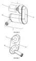
figure 6 présente schématiquement en trois dimensions l'invention selon un deuxième mode de réalisation. - La
figure 7 présente schématiquement une vue de côté de ce second mode de réalisation. - La
figure 8 présente schématiquement en trois dimensions l'invention selon un deuxième mode de réalisation. - La
figure 9 présente schématiquement une vue de côté de ce troisième mode de réalisation. - La
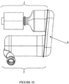
figure 10 présente schématiquement un quatrième mode de réalisation. - La
figure 1 présente un ensemble selon un mode de réalisation préférentiel de l'invention, selon une vue extérieure schématique en 3 dimensions. Lafigure 2 présente le même mode de réalisation, selon une vue en coupe partielle (les enveloppes contenant des monolithe de traitement des gaz d'échappement sont représentées schématiquement en coupe, de sorte à permettre de visualiser les différentes monolithes mis en jeu). Lesfigures 3 à 5 présentent de la même manière des variantes de réalisation. - Un ensemble selon l'invention comporte une première branche 1 rectiligne 1 et une seconde branche rectiligne 2. Dans l'invention, la première et la seconde branche sont sont sensiblement parallèles de sorte à former les deux branches d'une architecture en « U »,
- La première branche comporte un turbocompresseur 3 et, dans une enveloppe ou « canning » appropriée, un catalyseur d'oxydation 4. Le catalyseur d'oxydation sert principalement au traitement des hydrocarbures imbrûlés (HC) et du monoxyde de carbone (CO) dans le cadre d'un moteur Diesel.
- La seconde branche comporte un catalyseur de réduction catalytique sélective des oxydes d'azote, ou catalyseur SCR 5. La seconde branche comporte également un filtre à particule 6. Le catalyseur SCR 5 et le filtre à particules 6 peuvent, selon la variante de l'invention considérée, être contenus dans une enveloppe unique, voire être regroupés en un unique monolithe dit « FAP/SCR » 7, à savoir un filtre à particules portant une imprégnation de réduction catalytique sélective des oxydes d'azote.
- Le filtre à particule 6 est préférentiellement d'un type mettant en jeu un additif permettant d'abaisser la température d'oxydation des suies. Cette caractéristique permet au filtre de se régénérer à des températures plus basses qu'un filtre dit « catalysé » (désignant un filtre n'employant pas d'additif d'abaissement de la température d'oxydation des suies).
- La première branche 1 est reliée à la seconde branche par un raccord fluidique 8 permettant le transport des gaz d'échappement de la sortie de la première branche vers l'entrée de la seconde branche (les notions d'entrée et de sortie se comprenant dans l'ensemble du présent document selon le sens d'écoulement des gaz d'échappement dans l'ensemble selon l'invention).
- Ce raccord peut également avoir un rôle important dans le traitement des gaz d'échappement. En effet, la catalyse SCR nécessite l'introduction et le mélange dans les gaz d'échappement d'un réducteur (agent réducteur ou précurseur d'un tel agent) par des moyens appropriés tel qu'un injecteur dédié (non représentés sur les figures). L'embouchure d'un moyen d'introduction peut avantageusement être située dans le raccord fluidique 8, de préférence vers l'entrée du dit raccord afin de maximiser la distance entre le point d'introduction, de réducteur et le catalyseur SCR 5, une telle distance favorisant le mélange du réducteur dans les gaz d'échappement.
- La forme du raccord 8 peut également être optimisée de sorte à favoriser (voire totalement réaliser) le mélange homogène du réducteur et des gaz d'échappement.
- Une configuration en U telle que proposée dans l'invention est d'ailleurs favorable à ce phénomène.
- Le raccord 8 confère à l'ensemble en U, dans l'optique d'une application automobile, une largeur maximale de 600mm et pourra notamment lui conférer une largeur de l'ordre de 380mm. La largeur du U désigne la largeur hors tout entre les deux branches.
- L'invention présente des première et seconde branches sensiblement parallèles. La notion de forme en « U » doit s'interpréter de manière restrictive, de sorte qu'une forme sensiblement plus proche d'un « V » ne peut pas entrer dans la définition de l'invention. On considérerait alors la largeur maximale du « V ». En revanche, les deux branches du U constituées respectivement par la première branche 1 et la seconde branche 2 peuvent bien évidemment être reliées par un raccord 8 courbe ou droit sans sortir du cadre de l'invention.
- La notion de « U » ne préjuge pas de son orientation en utilisation. Ainsi, dans une application automobile, les première et seconde branche pourront (et seront généralement) positionnées sensiblement horizontalement.
- Dans la variante préférentielle de l'invention ici présentée, et ce à toutes les figures, le raccord 8 est constitué d'une plaque de liaison entre la première branche 1 et la seconde branche 2, et d'une coupelle creuse formant ainsi un corps creux faisant raccord.
- Le raccord 8 peut comporter un mélangeur 9 rapporté, c'est-à-dire un dispositif apte à générer des turbulences et/ou à augmenter la distance parcourue par les gaz d'échappement de sorte à favoriser leur mélange homogène avec le réducteur, ou augmenter leur temps de transport avant l'atteinte du catalyseur SCR, afin par exemple de permettre la transformation en agent réducteur d'un précurseur d'un tel agent.
- Un mélangeur 9 peut, selon la variante de l'invention considérée, être disposé dans la seconde branche en amont du catalyseur SCR 5 ou du monolithe FAP/SCR 7. On peut dans ce cadre employer préférentiellement un mélangeur du type connu au travers du document
FR2947003 - La seconde branche inclut également un convergent de sortie 10 afin de canaliser les gaz d'échappement traité par l'ensemble selon l'invention. Ce convergent présente préférentiellement une évacuation latérale. Cela permet d'en limiter la longueur et d'orienter le flux des gaz d'échappement de manière adéquate.
- De préférence, la première branche 1 et la seconde branche 2 présentent des longueurs sensiblement égales. Ceci est rendu possible par la répartition des fonctions proposée dans l'invention à savoir, la suralimentation et la catalyse des HC et CO dans la première branche 1, le traitement des NOx et des particules dans la seconde branche 2. De cette répartition découle un avantage majeur en termes de facilité d'implantation d'un ensemble selon l'invention.
- Pour une application automobile classique présentant un moteur de type Diesel, on pourra notamment employer :
- un turbocompresseur du type à géométrie fixe ou variable ;
- un catalyseur d'oxydation d'un diamètre compris entre 114mm (4,5 pouces) et 178mm (7pouces) et préférentiellement de l'ordre de 144 mm (5,66 pouces) et d'une longueur de 76mm à 127mm (3 à 5 pouces), et de préférence de l'ordre de 102mm (4 pouces) ;
- un monolithe FAP/SR d'un diamètre compris entre 114mm (4,5 pouces) et 178mm (7pouces) et préférentiellement de l'ordre de 144 mm (5,66 pouces) et d'une longueur de 127mm à 203mm (5 à 8 pouces), et de préférence de l'ordre de 152mm (6 pouces) ;
- Dans une application automobile, la hauteur du U c'est-à-dire la longueur de la plus grande des branches à laquelle s'ajoute la dimension du raccord selon l'axe de la branche, sera préférentiellement inférieure à 600mm et pourra notamment être de l'ordre de 400mm.
- Il est également possible d'employer des monolithes de traitement qui ne sont pas cylindriques ronds. Les
figures 6 et 7 illustrent cela avec des monolithes de section ovalisée. - Il est possible d'employer des monolithes cylindriques ronds en combinaison avec des monolithes non cylindriques ronds. Les
figures 8 et 9 présentent ainsi un dispositif selon l'invention comportant un catalyseur d'oxydation ovalisé et des fonctions de traitement des NOx et des particules par un ou plusieurs monolithes cylindriques ronds. - Enfin, le raccord 8 peut être oblique vis-à-vis des deux branches, sans sortir du cadre de l'invention, tel que présenté en
figure 10 . Cette architecture avec raccord 8 oblique est compatible de toutes les variantes de l'invention, par exemple avec des monolithes de traitement cylindriques ronds, ovalisés, ou avec un mélange de monolithes cylindriques rond et ovalisés. - L'invention ainsi développée, en permettant une répartition suivant deux axes des éléments de dépollution, favorise l'implantation d'un ensemble complet de traitement des gaz d'échappement d'un moteur à combustion dans un environnement contraint où l'ensemble ne peut être implanté suivant un seul axe. Positionner le catalyseur d'oxydation au plus près de la sortie du turbocompresseur permet de limiter les déperditions thermiques et de limiter les inerties thermiques s'opposant au chauffage rapide du catalyseur d'oxydation par les gaz d'échappement (une inertie thermique importante est pénalisant pour l'amorçage du catalyseur, notamment dans le cadre des cycles normalisés d'homologation). Positionner le catalyseur d'oxydation directement en sortie dans l'alignement de la sortie du turbocompresseur est la meilleure architecture pour permettre un amorçage rapide du catalyseur d'oxydation, et permet donc d'en limiter la dimension. En outre les pertes de charge sont entre la turbine et le catalyseur sont limitées.
- De même, un positionnement au plus près de la sortie de la turbine du catalyseur SCR favorise sa montée rapide en température, et donc son amorçage. Un choix de pièces intermédiaires, et notamment du raccord, de faible dimension et présentant une faible inertie thermique permet d'optimiser cette montée en température.
- Une architecture selon l'invention permet donc un cercle vertueux quant au dimensionnement des monolithes de traitement des gaz d'échappement, ce qui en facilite d'autant plus l'implantation dans un environnement contraint et en réduit le coût.
- Une architecture selon l'invention, avec une première et une seconde branche non coaxiale favorise en outre le mélange d'un réducteur SCR introduit en amont de la seconde branche, par exemple dans le raccord. Avec un raccord comportant une coupelle creuse, il est notamment possible d'optimiser sa forme pour favoriser au maximum le mélange du réducteur dans les gaz d'échappement.
- Enfin, l'implantation d'un ensemble selon l'invention dans un espace sous-capot moteur d'un véhicule automobile offre un potentiel de gain de masse important par rapport aux architectures connues, notamment en permettant la suppression de tout dispositif de post-traitement sous caisse ainsi que tout dispositif de calfeutrage (écrans thermiques, etc.) généralement disposés sous le plancher du véhicule pour minimiser les pertes thermiques avant l'entrée dans les moyens de traitement des gaz implanté sous le plancher.
Claims (18)
- Ensemble de post-traitement des gaz d'échappement d'un moteur à combustion suralimenté par un turbocompresseur comportant, selon le sens d'écoulement des gaz d'échappement du moteur :• un turbocompresseur (3) comprenant une turbine;• un catalyseur d'oxydation (4);• un catalyseur de réduction catalytique sélective des oxydes d'azote (5);• un filtre à particules (6);caractérisé en ce que l'ensemble est disposé selon une architecture sensiblement en « U » comportant :• une première et une seconde branche sensiblement parallèles ;• la première branche (1) rectiligne comportant le turbocompresseur (3) et le catalyseur d'oxydation (4), une enveloppe du catalyseur d'oxydation (4) étant directement raccordée en sortie de la turbine du turbocompresseur (3) ;• la seconde branche (2) rectiligne comportant le catalyseur de réduction catalytique sélective des oxydes d'azote (5) et le filtre à particules (6) ;• et un raccord (8) fluidique entre les première et seconde branches (1,2).
- Ensemble selon la revendication 1, caractérisé en ce que le filtre à particule (6) est du type à mettant en jeu un additif abaissant la température d'oxydation des particules de suie.
- Ensemble selon la revendication 1, comportant en outre entre le catalyseur d'oxydation (4) et le catalyseur de réduction catalytique sélective des oxydes d'azote (5) :• une embouchure d'un moyen d'introduction de réducteur ou de précurseur d'un réducteur pour la réduction catalytique sélective des oxydes d'azote ;• des moyens de mélange aptes à assurer un mélange sensiblement homogène des gaz d'échappement et du réducteur et/ou la conversion du précurseur en réducteur.
- Ensemble selon la revendication 3, dans lequel l'embouchure du moyen d'introduction est située dans le raccord (8) fluidique.
- Ensemble selon la revendication 4, dans lequel l'embouchure du moyen d'introduction est située vers l'entrée du raccord (8) fluidique.
- Ensemble selon l'une des revendications 3 à 5, dans lequel le raccord forme ou comporte les moyens de mélange.
- Ensemble selon l'une des revendications 3 à 5, dans lequel les moyens de mélanges comportent un mélangeur (9) dans la seconde branche.
- Ensemble selon l'une des revendications 1 à 7, dans lequel la seconde branche (2) comporte une enveloppe unique regroupant le catalyseur de réduction catalytique sélective des oxydes d'azote (5) et le filtre à particules (6).
- Ensemble selon la revendication 8, dans lequel le catalyseur de réduction catalytique sélective des oxydes d'azote (5) et le filtre à particules (6) sont constitués par un unique monolithe (7) de traitement des gaz d'échappement.
- Ensemble selon la revendication 9, dans lequel le filtre à particules porte une imprégnation catalytique sélective des oxydes d'azote.
- Ensemble selon l'une des revendications précédentes, dans lequel la seconde branche (2) comporte un convergent (10) à évacuation latérale.
- Ensemble selon l'une des revendications précédentes, dans lequel le raccord (8) forme une troisième branche droite entre la sortie de la première branche (1) et l'entrée de la seconde branche (2).
- Ensemble selon la revendication 12, dans lequel la troisième branche est orthogonale aux première et seconde branches (1,2), et présente un coude à angle droit à chacune de ses extrémités pour son raccordement aux premières et secondes branches (1,2).
- Ensemble selon l'une des revendications précédentes, dans lequel le raccord (8) comporte une plaque de jonction entre la première branche (1) et la seconde branche (2), plaque surmontée d'une coupelle creuse.
- Ensemble selon l'une des revendications précédentes, dans lequel que le U présente une largeur d'au plus 600mm, et de préférence de l'ordre de 380mm.
- Ensemble selon l'une quelconque des revendications précédentes, dans lequel le U présente une hauteur d'au plus 600mm et de préférence de l'ordre de 400mm.
- Ensemble selon l'une quelconque des revendications précédentes, présentant au moins une des caractéristiques suivantes :• le catalyseur d'oxydation (4) présente une densité de cellule comprise entre 62 et 140 cellules par centimètre carré, et de préférence de l'ordre de 93 cellules par centimètres carré ;• le catalyseur d'oxydation (4) présente une épaisseur de paroi comprise entre 50 µm et 165 µm ;• le catalyseur de réduction catalytique sélective des oxydes d'azote (6) présente une densité de cellule comprise entre 62 et 140 cellules par centimètre carré, et de préférence de l'ordre de 93 cellules par centimètres carré ;• le catalyseur de réduction catalytique sélective des oxydes d'azote (6) présente une épaisseur de paroi comprise entre 50 µm et 165 µm ;
- Véhicule automobile comportant un moteur à combustion interne disposé dans un espace sous-capot, caractérisé en ce qu'il comprend un ensemble selon l'une quelconque des revendications précédentes dans le dit espace sous-capot.
Applications Claiming Priority (2)
| Application Number | Priority Date | Filing Date | Title |
|---|---|---|---|
| FR1151374A FR2971810B1 (fr) | 2011-02-18 | 2011-02-18 | Ensemble de post-traitement des gaz d'echappement d'un moteur a combustion suralimente, et vehicule automobile comportant un tel ensemble |
| PCT/FR2012/050073 WO2012110720A1 (fr) | 2011-02-18 | 2012-01-11 | Ensemble de post-traitement des gaz d'echappement d'un moteur a combustion suralimente, et vehicule automobile comportant un tel ensemble |
Publications (3)
| Publication Number | Publication Date |
|---|---|
| EP2676016A1 EP2676016A1 (fr) | 2013-12-25 |
| EP2676016B1 EP2676016B1 (fr) | 2015-10-14 |
| EP2676016B2 true EP2676016B2 (fr) | 2025-02-12 |
Family
ID=45755366
Family Applications (1)
| Application Number | Title | Priority Date | Filing Date |
|---|---|---|---|
| EP12705320.5A Active EP2676016B2 (fr) | 2011-02-18 | 2012-01-11 | Ensemble de post-traitement des gaz d'echappement d'un moteur a combustion suralimente, et vehicule automobile comportant un tel ensemble |
Country Status (3)
| Country | Link |
|---|---|
| EP (1) | EP2676016B2 (fr) |
| FR (1) | FR2971810B1 (fr) |
| WO (1) | WO2012110720A1 (fr) |
Families Citing this family (41)
| Publication number | Priority date | Publication date | Assignee | Title |
|---|---|---|---|---|
| FR2972764B1 (fr) * | 2011-03-16 | 2013-03-29 | Peugeot Citroen Automobiles Sa | Ensemble compact coude de post-traitement de gaz d'echappement dote d'un bossage formant melangeur de reducteur scr |
| DE102011111590A1 (de) * | 2011-08-25 | 2013-02-28 | Volkswagen Aktiengesellschaft | Abgasbehandlungseinrichtung, Verfahren zur Aufbereitung von Abgas und Kraftfahrzeug |
| DE102012009940A1 (de) * | 2012-05-18 | 2013-11-21 | Daimler Ag | Crashtolerante Systemanordnung in einem Kraftfahrzeugmotorraum |
| DE102012214285A1 (de) * | 2012-08-10 | 2014-02-13 | Friedrich Boysen Gmbh & Co. Kg | Vorrichtung zum Führen eines Gasstroms |
| DE102012023049A1 (de) * | 2012-11-26 | 2014-05-28 | Volkswagen Aktiengesellschaft | SCR-Abgasnachbehandlungseinrichtung sowie Kraftfahrzeug mit einer solchen |
| WO2014167352A1 (fr) | 2013-04-11 | 2014-10-16 | Perkins Engines Company Limited | Bouclier thermique et module de suppression d'émissions |
| CN105247183B (zh) | 2013-04-11 | 2018-06-12 | 珀金斯发动机有限公司 | 流罩和排放物清洁模块 |
| JP6090208B2 (ja) | 2014-02-27 | 2017-03-08 | マツダ株式会社 | エンジンの排気装置 |
| FR3019062B1 (fr) * | 2014-03-26 | 2016-04-15 | Peugeot Citroen Automobiles Sa | Ensemble de depollution des gaz de combustion |
| JP6156228B2 (ja) * | 2014-03-31 | 2017-07-05 | マツダ株式会社 | 排気ガス浄化装置 |
| DE102014211159A1 (de) * | 2014-06-11 | 2015-12-17 | Volkswagen Aktiengesellschaft | Vorrichtung zur katalytischen chemischen Umsetzungwenigstens einer Komponente eines Gasstromsund Abgasanlage für eine Brennkraftmaschine |
| FR3029969A1 (fr) * | 2014-12-10 | 2016-06-17 | Peugeot Citroen Automobiles Sa | Dispositif de post-traitement des gaz d’echappement d’un moteur a combustion |
| EP3085916B1 (fr) * | 2015-04-22 | 2018-12-26 | Faurecia Systèmes d'Echappement | Dispositif de purification des gaz d'échappement et ligne d'échappement comprenant un tel dispositif |
| US9879581B2 (en) | 2016-03-25 | 2018-01-30 | Caterpillar Inc. | After-treatment system |
| DE102016213414A1 (de) | 2016-07-22 | 2018-01-25 | Bayerische Motoren Werke Aktiengesellschaft | Abgasanlage für eine Brennkraftmaschine |
| JP6361704B2 (ja) * | 2016-07-26 | 2018-07-25 | マツダ株式会社 | エンジンの排気構造 |
| US10022667B2 (en) * | 2016-07-29 | 2018-07-17 | Cummins Inc. | Systems and methods for increasing nitrogen dioxide fraction in exhaust gas at low temperature |
| CN108252773B (zh) * | 2016-12-28 | 2022-01-18 | 罗伯特·博世有限公司 | 具有并排布置的尾气处理元件的尾气后处理箱 |
| CN108252771B (zh) * | 2016-12-28 | 2021-11-30 | 罗伯特·博世有限公司 | 利用处理后的尾气进行保温的尾气后处理箱 |
| DE102017206794A1 (de) | 2017-04-24 | 2018-10-25 | Bayerische Motoren Werke Aktiengesellschaft | Abgasanlage für eine Brennkraftmaschine |
| US11136910B2 (en) | 2017-06-06 | 2021-10-05 | Cummins Emission Solutions Inc. | Systems and methods for mixing exhaust gases and reductant in an aftertreatment system |
| JP6508302B2 (ja) * | 2017-11-30 | 2019-05-08 | マツダ株式会社 | エンジンの排気装置 |
| JP2018040370A (ja) * | 2017-11-30 | 2018-03-15 | マツダ株式会社 | エンジンの排気装置 |
| JP6508300B2 (ja) * | 2017-11-30 | 2019-05-08 | マツダ株式会社 | エンジンの排気装置 |
| JP6508301B2 (ja) * | 2017-11-30 | 2019-05-08 | マツダ株式会社 | エンジンの排気装置 |
| JP2020012433A (ja) * | 2018-07-19 | 2020-01-23 | いすゞ自動車株式会社 | 車載エンジンの排気構造 |
| JP2019082181A (ja) * | 2019-02-28 | 2019-05-30 | マツダ株式会社 | エンジンの排気装置 |
| US10876450B2 (en) * | 2019-05-22 | 2020-12-29 | FEV Europe GmbH | Splitflow catalyst system |
| EP4069954A4 (fr) | 2019-12-03 | 2023-08-09 | Cummins Emission Solutions Inc. | Système de distribution de réducteur pour système de post-traitement de gaz d'échappement |
| WO2021173357A1 (fr) | 2020-02-27 | 2021-09-02 | Cummins Emission Solutions Inc. | Mélangeurs destinés à être utilisés dans des systèmes de post-traitement |
| GB2609163B (en) | 2020-05-08 | 2023-08-23 | Cummins Emission Solutions Inc | Configurable aftertreatment systems including a housing |
| US12173632B2 (en) | 2020-10-22 | 2024-12-24 | Cummins Emission Solutions Inc. | Exhaust gas aftertreatment system |
| US12352196B2 (en) | 2021-02-02 | 2025-07-08 | Cummins Emission Solutions Inc. | Exhaust gas aftertreatment system |
| US12123337B2 (en) | 2021-03-18 | 2024-10-22 | Cummins Emission Solutions Inc. | Aftertreatment systems |
| DE102021111759A1 (de) * | 2021-05-06 | 2022-11-10 | Purem GmbH | Abgasbehandlungsmodul |
| CN117396668A (zh) | 2021-07-27 | 2024-01-12 | 康明斯排放处理公司 | 废气后处理系统 |
| US11428141B1 (en) | 2021-08-04 | 2022-08-30 | Ford Global Technologies, Llc | Integrated turbo and catalyst |
| CN119643152A (zh) | 2021-08-23 | 2025-03-18 | 康明斯排放处理公司 | 用于后处理系统的出口取样系统 |
| USD1042545S1 (en) | 2022-04-21 | 2024-09-17 | Cummins Emission Solutions Inc. | Aftertreatment system |
| USD1042544S1 (en) | 2022-04-21 | 2024-09-17 | Cummins Emission Solutions Inc. | Aftertreatment system |
| CN114991926A (zh) * | 2022-06-29 | 2022-09-02 | 东风商用车有限公司 | 应用于倾斜后处理器的安装结构 |
Family Cites Families (26)
| Publication number | Priority date | Publication date | Assignee | Title |
|---|---|---|---|---|
| FR1050453A (fr) | 1950-11-22 | 1954-01-07 | Westinghouse Electric Corp | Dépoussiéreurs électrostatiques |
| US3565830A (en) | 1963-02-07 | 1971-02-23 | Engelhard Min & Chem | Coated film of catalytically active oxide on a refractory support |
| US4335023A (en) | 1980-01-24 | 1982-06-15 | Engelhard Corporation | Monolithic catalyst member and support therefor |
| DE4007516C2 (de) | 1990-03-09 | 1997-03-06 | Kloeckner Humboldt Deutz Ag | Dieselmotor |
| ATE250969T1 (de) | 1997-07-28 | 2003-10-15 | Siemens Ag | Verwendung eines statischer mischers als hydrilysekatalysator sowie dessen verwendung in einer abgasleitung für eine verbrennungsanlage |
| FR2810075B1 (fr) | 2000-06-08 | 2005-08-12 | Peugeot Citroen Automobiles Sa | Vehicule automobile a moteur thermique comportant une ligne d'echappement ayant un systeme de depollution place a l'avant du moteur |
| FR2810072B1 (fr) * | 2000-06-08 | 2004-07-16 | Peugeot Citroen Automobiles Sa | Vehicule automobile comportant un filtre a particules a l'interieur du compartiment moteur et procede et installation de nettoyage du filtre a particules |
| US6722123B2 (en) | 2001-10-17 | 2004-04-20 | Fleetguard, Inc. | Exhaust aftertreatment device, including chemical mixing and acoustic effects |
| GB2381218B (en) | 2001-10-25 | 2004-12-15 | Eminox Ltd | Gas treatment apparatus |
| DE10323607B4 (de) | 2003-05-20 | 2019-05-09 | Robert Bosch Gmbh | Vorrichtung zur Reinigung von Abgasen eines Verbrennungsmotors |
| US7229597B2 (en) | 2003-08-05 | 2007-06-12 | Basfd Catalysts Llc | Catalyzed SCR filter and emission treatment system |
| JP2005155404A (ja) * | 2003-11-25 | 2005-06-16 | Komatsu Ltd | 内燃機関の排気ガス浄化装置 |
| US8015802B2 (en) | 2004-11-25 | 2011-09-13 | Komatsu Ltd. | Exhaust gas purification device for internal combustion engine |
| US7263824B2 (en) | 2004-12-03 | 2007-09-04 | Cummins, Inc. | Exhaust gas aftertreatment device for an internal combustion engine |
| DE102005039630B4 (de) | 2005-08-20 | 2007-08-02 | Technische Universität Kaiserslautern | Vorrichtung, Reaktor und Verfahren zur Reduzierung von Stickoxyden im Abgasstrom von Verbrennungskraftmaschinen |
| JP4698359B2 (ja) * | 2005-09-22 | 2011-06-08 | Udトラックス株式会社 | 排気浄化装置 |
| DE102007011184A1 (de) | 2007-03-06 | 2008-09-11 | Behr Gmbh & Co. Kg | Wärmetauscher zur Kühlung von Abgas, Vorrichtung zur Überführung einer flüssigen Harnstofflösung in zumindest gasförmiges Ammoniak, System zur Abgaskühlung, Verfahren zur Rückführung von Abgas und zur Stickoxidreduzierung |
| CN101627190B (zh) | 2007-03-12 | 2012-05-30 | 博世株式会社 | 内燃机的排气净化装置 |
| JP5044359B2 (ja) | 2007-10-23 | 2012-10-10 | 三菱ふそうトラック・バス株式会社 | エンジンの排気浄化装置 |
| US8381512B2 (en) * | 2008-05-02 | 2013-02-26 | GM Global Technology Operations LLC | Passive ammonia-selective catalytic reduction for NOx control in internal combustion engines |
| JP5256881B2 (ja) | 2008-06-25 | 2013-08-07 | いすゞ自動車株式会社 | 排気ガス浄化装置 |
| US8475752B2 (en) | 2008-06-27 | 2013-07-02 | Basf Corporation | NOx adsorber catalyst with superior low temperature performance |
| JP5308176B2 (ja) | 2009-02-03 | 2013-10-09 | ヤンマー株式会社 | 排気浄化装置 |
| DE102009007765A1 (de) | 2009-02-06 | 2010-08-12 | Daimler Ag | Verfahren zum Betreiben einer Brennkraftmaschine mit einer einen SCR-Katalysator umfassenden Abgasreinigungsanlage |
| FR2943383B1 (fr) | 2009-03-23 | 2011-03-25 | Renault Sas | Circuit d'alimentation et d'echappement de vehicule automobile |
| FR2947003B1 (fr) | 2009-06-19 | 2015-04-10 | Faurecia Sys Echappement | Ligne d'echappement avec systeme d'injection |
-
2011
- 2011-02-18 FR FR1151374A patent/FR2971810B1/fr active Active
-
2012
- 2012-01-11 WO PCT/FR2012/050073 patent/WO2012110720A1/fr not_active Ceased
- 2012-01-11 EP EP12705320.5A patent/EP2676016B2/fr active Active
Also Published As
| Publication number | Publication date |
|---|---|
| FR2971810B1 (fr) | 2013-03-15 |
| EP2676016A1 (fr) | 2013-12-25 |
| WO2012110720A1 (fr) | 2012-08-23 |
| EP2676016B1 (fr) | 2015-10-14 |
| FR2971810A1 (fr) | 2012-08-24 |
Similar Documents
| Publication | Publication Date | Title |
|---|---|---|
| EP2676016B2 (fr) | Ensemble de post-traitement des gaz d'echappement d'un moteur a combustion suralimente, et vehicule automobile comportant un tel ensemble | |
| EP2686529B1 (fr) | Ensemble coudé de post-traitement des gaz d'echappement d'un moteur a combustion, groupe motopropulseur et vehicule associés | |
| EP2529091B1 (fr) | Dispositif de post-traitement des gaz d'échappement d'un moteur à combustion interne | |
| EP2522822B1 (fr) | Système comportant un moteur à combustion, un ensemble en « U » de traitement des gaz d'échappement, et un écran thermique optimisé | |
| EP2551482B1 (fr) | Ensemble coude de post-traitement des gaz d'echappement d'un moteur à combustion comportant un convergent interne | |
| EP2546488B1 (fr) | Ensemble coudé de post-traitement des gaz d'échappement d'un moteur à combustion interne comportant un répartiteur d'agent réducteur par impacteur | |
| FR2966197A1 (fr) | Ligne d'echappement pour vehicule automobile. | |
| FR2964413A1 (fr) | Filtre a particules a trois revetements catalytiques | |
| FR2945576A1 (fr) | Melangeur, dispositif de depollution et ligne d'echappement equipee de ce melangeur. | |
| FR2974595A1 (fr) | Enveloppe coudee d'un ensemble de post-traitement des gaz d'echappement d'un moteur a combustion comportant deux demi-coquilles | |
| FR3081921A1 (fr) | Ligne d’echappement de moteur thermique comprenant un element de chauffage amont | |
| EP2678536A1 (fr) | Vehicule automobile comportant une ligne d'echappement dont les moyens acoustiques sont disposes en avant du train arriere | |
| FR3037101A1 (fr) | Ligne d’echappement d’un moteur thermique | |
| FR3100839A1 (fr) | Ensemble comprenant un moteur à combustion interne avec un compresseur électrique et un élément chauffant | |
| EP3149300A1 (fr) | Dispositif de post-traitement des gaz d'échappement d'un moteur a combustion | |
| FR2955612A1 (fr) | Dispositif de post-traitement des gaz d'echappement d'un moteur a combustion | |
| FR2960593A1 (fr) | Dispositif de post-traitement des gaz d'echappement d'un moteur a combustion | |
| FR3037615B1 (fr) | Systeme de depollution des gaz d'echappement optimise | |
| FR3066541A1 (fr) | Systeme de post-traitement des gaz d'echappement d'un moteur a combustion interne | |
| FR2971005A1 (fr) | Ligne d'echappement pour moteur a combustion interne | |
| FR2986826A1 (fr) | Dispositif de traitement des gaz d'echappement d'un moteur a combustion et vehicule automobile associe | |
| FR2933448A1 (fr) | Dispositif de purification de gaz d'echappement | |
| WO2010100352A1 (fr) | Dispositif et procede de traitement des oxydes d'azote contenus dans des gaz d'echappement |
Legal Events
| Date | Code | Title | Description |
|---|---|---|---|
| PUAI | Public reference made under article 153(3) epc to a published international application that has entered the european phase |
Free format text: ORIGINAL CODE: 0009012 |
|
| 17P | Request for examination filed |
Effective date: 20130820 |
|
| AK | Designated contracting states |
Kind code of ref document: A1 Designated state(s): AL AT BE BG CH CY CZ DE DK EE ES FI FR GB GR HR HU IE IS IT LI LT LU LV MC MK MT NL NO PL PT RO RS SE SI SK SM TR |
|
| RIN1 | Information on inventor provided before grant (corrected) |
Inventor name: CEREIJO, MANUEL Inventor name: FERHAN, MEHDI Inventor name: LERE, SYLVAIN Inventor name: FERRAND, NICOLAS Inventor name: TRAIZET, GREGOIRE |
|
| DAX | Request for extension of the european patent (deleted) | ||
| 17Q | First examination report despatched |
Effective date: 20140709 |
|
| GRAP | Despatch of communication of intention to grant a patent |
Free format text: ORIGINAL CODE: EPIDOSNIGR1 |
|
| INTG | Intention to grant announced |
Effective date: 20150630 |
|
| GRAS | Grant fee paid |
Free format text: ORIGINAL CODE: EPIDOSNIGR3 |
|
| GRAA | (expected) grant |
Free format text: ORIGINAL CODE: 0009210 |
|
| AK | Designated contracting states |
Kind code of ref document: B1 Designated state(s): AL AT BE BG CH CY CZ DE DK EE ES FI FR GB GR HR HU IE IS IT LI LT LU LV MC MK MT NL NO PL PT RO RS SE SI SK SM TR |
|
| REG | Reference to a national code |
Ref country code: GB Ref legal event code: FG4D Free format text: NOT ENGLISH |
|
| REG | Reference to a national code |
Ref country code: AT Ref legal event code: REF Ref document number: 755269 Country of ref document: AT Kind code of ref document: T Effective date: 20151015 Ref country code: CH Ref legal event code: EP |
|
| REG | Reference to a national code |
Ref country code: IE Ref legal event code: FG4D Free format text: LANGUAGE OF EP DOCUMENT: FRENCH |
|
| REG | Reference to a national code |
Ref country code: DE Ref legal event code: R096 Ref document number: 602012011525 Country of ref document: DE |
|
| REG | Reference to a national code |
Ref country code: FR Ref legal event code: PLFP Year of fee payment: 5 |
|
| REG | Reference to a national code |
Ref country code: DE Ref legal event code: R084 Ref document number: 602012011525 Country of ref document: DE |
|
| REG | Reference to a national code |
Ref country code: GB Ref legal event code: 746 Effective date: 20160119 |
|
| REG | Reference to a national code |
Ref country code: NL Ref legal event code: MP Effective date: 20151014 |
|
| REG | Reference to a national code |
Ref country code: LT Ref legal event code: MG4D |
|
| REG | Reference to a national code |
Ref country code: AT Ref legal event code: MK05 Ref document number: 755269 Country of ref document: AT Kind code of ref document: T Effective date: 20151014 |
|
| PG25 | Lapsed in a contracting state [announced via postgrant information from national office to epo] |
Ref country code: HR Free format text: LAPSE BECAUSE OF FAILURE TO SUBMIT A TRANSLATION OF THE DESCRIPTION OR TO PAY THE FEE WITHIN THE PRESCRIBED TIME-LIMIT Effective date: 20151014 Ref country code: ES Free format text: LAPSE BECAUSE OF FAILURE TO SUBMIT A TRANSLATION OF THE DESCRIPTION OR TO PAY THE FEE WITHIN THE PRESCRIBED TIME-LIMIT Effective date: 20151014 Ref country code: LT Free format text: LAPSE BECAUSE OF FAILURE TO SUBMIT A TRANSLATION OF THE DESCRIPTION OR TO PAY THE FEE WITHIN THE PRESCRIBED TIME-LIMIT Effective date: 20151014 Ref country code: IT Free format text: LAPSE BECAUSE OF FAILURE TO SUBMIT A TRANSLATION OF THE DESCRIPTION OR TO PAY THE FEE WITHIN THE PRESCRIBED TIME-LIMIT Effective date: 20151014 Ref country code: NL Free format text: LAPSE BECAUSE OF FAILURE TO SUBMIT A TRANSLATION OF THE DESCRIPTION OR TO PAY THE FEE WITHIN THE PRESCRIBED TIME-LIMIT Effective date: 20151014 Ref country code: IS Free format text: LAPSE BECAUSE OF FAILURE TO SUBMIT A TRANSLATION OF THE DESCRIPTION OR TO PAY THE FEE WITHIN THE PRESCRIBED TIME-LIMIT Effective date: 20160214 Ref country code: NO Free format text: LAPSE BECAUSE OF FAILURE TO SUBMIT A TRANSLATION OF THE DESCRIPTION OR TO PAY THE FEE WITHIN THE PRESCRIBED TIME-LIMIT Effective date: 20160114 |
|
| PG25 | Lapsed in a contracting state [announced via postgrant information from national office to epo] |
Ref country code: LV Free format text: LAPSE BECAUSE OF FAILURE TO SUBMIT A TRANSLATION OF THE DESCRIPTION OR TO PAY THE FEE WITHIN THE PRESCRIBED TIME-LIMIT Effective date: 20151014 Ref country code: AT Free format text: LAPSE BECAUSE OF FAILURE TO SUBMIT A TRANSLATION OF THE DESCRIPTION OR TO PAY THE FEE WITHIN THE PRESCRIBED TIME-LIMIT Effective date: 20151014 Ref country code: GR Free format text: LAPSE BECAUSE OF FAILURE TO SUBMIT A TRANSLATION OF THE DESCRIPTION OR TO PAY THE FEE WITHIN THE PRESCRIBED TIME-LIMIT Effective date: 20160115 Ref country code: RS Free format text: LAPSE BECAUSE OF FAILURE TO SUBMIT A TRANSLATION OF THE DESCRIPTION OR TO PAY THE FEE WITHIN THE PRESCRIBED TIME-LIMIT Effective date: 20151014 Ref country code: PL Free format text: LAPSE BECAUSE OF FAILURE TO SUBMIT A TRANSLATION OF THE DESCRIPTION OR TO PAY THE FEE WITHIN THE PRESCRIBED TIME-LIMIT Effective date: 20151014 Ref country code: SE Free format text: LAPSE BECAUSE OF FAILURE TO SUBMIT A TRANSLATION OF THE DESCRIPTION OR TO PAY THE FEE WITHIN THE PRESCRIBED TIME-LIMIT Effective date: 20151014 Ref country code: FI Free format text: LAPSE BECAUSE OF FAILURE TO SUBMIT A TRANSLATION OF THE DESCRIPTION OR TO PAY THE FEE WITHIN THE PRESCRIBED TIME-LIMIT Effective date: 20151014 Ref country code: PT Free format text: LAPSE BECAUSE OF FAILURE TO SUBMIT A TRANSLATION OF THE DESCRIPTION OR TO PAY THE FEE WITHIN THE PRESCRIBED TIME-LIMIT Effective date: 20160215 Ref country code: BE Free format text: LAPSE BECAUSE OF NON-PAYMENT OF DUE FEES Effective date: 20160131 |
|
| REG | Reference to a national code |
Ref country code: DE Ref legal event code: R026 Ref document number: 602012011525 Country of ref document: DE |
|
| PLBI | Opposition filed |
Free format text: ORIGINAL CODE: 0009260 |
|
| PLBI | Opposition filed |
Free format text: ORIGINAL CODE: 0009260 |
|
| 26 | Opposition filed |
Opponent name: VOLKSWAGEN AKTIENGESELLSCHAFT Effective date: 20160620 |
|
| PG25 | Lapsed in a contracting state [announced via postgrant information from national office to epo] |
Ref country code: CZ Free format text: LAPSE BECAUSE OF FAILURE TO SUBMIT A TRANSLATION OF THE DESCRIPTION OR TO PAY THE FEE WITHIN THE PRESCRIBED TIME-LIMIT Effective date: 20151014 |
|
| 26 | Opposition filed |
Opponent name: TENNECO GMBH Effective date: 20160713 |
|
| PLAX | Notice of opposition and request to file observation + time limit sent |
Free format text: ORIGINAL CODE: EPIDOSNOBS2 |
|
| PG25 | Lapsed in a contracting state [announced via postgrant information from national office to epo] |
Ref country code: LU Free format text: LAPSE BECAUSE OF FAILURE TO SUBMIT A TRANSLATION OF THE DESCRIPTION OR TO PAY THE FEE WITHIN THE PRESCRIBED TIME-LIMIT Effective date: 20160111 Ref country code: RO Free format text: LAPSE BECAUSE OF FAILURE TO SUBMIT A TRANSLATION OF THE DESCRIPTION OR TO PAY THE FEE WITHIN THE PRESCRIBED TIME-LIMIT Effective date: 20151014 Ref country code: EE Free format text: LAPSE BECAUSE OF FAILURE TO SUBMIT A TRANSLATION OF THE DESCRIPTION OR TO PAY THE FEE WITHIN THE PRESCRIBED TIME-LIMIT Effective date: 20151014 Ref country code: SM Free format text: LAPSE BECAUSE OF FAILURE TO SUBMIT A TRANSLATION OF THE DESCRIPTION OR TO PAY THE FEE WITHIN THE PRESCRIBED TIME-LIMIT Effective date: 20151014 Ref country code: DK Free format text: LAPSE BECAUSE OF FAILURE TO SUBMIT A TRANSLATION OF THE DESCRIPTION OR TO PAY THE FEE WITHIN THE PRESCRIBED TIME-LIMIT Effective date: 20151014 Ref country code: SK Free format text: LAPSE BECAUSE OF FAILURE TO SUBMIT A TRANSLATION OF THE DESCRIPTION OR TO PAY THE FEE WITHIN THE PRESCRIBED TIME-LIMIT Effective date: 20151014 |
|
| REG | Reference to a national code |
Ref country code: CH Ref legal event code: PL |
|
| PG25 | Lapsed in a contracting state [announced via postgrant information from national office to epo] |
Ref country code: MC Free format text: LAPSE BECAUSE OF FAILURE TO SUBMIT A TRANSLATION OF THE DESCRIPTION OR TO PAY THE FEE WITHIN THE PRESCRIBED TIME-LIMIT Effective date: 20151014 |
|
| PG25 | Lapsed in a contracting state [announced via postgrant information from national office to epo] |
Ref country code: CH Free format text: LAPSE BECAUSE OF NON-PAYMENT OF DUE FEES Effective date: 20160131 Ref country code: LI Free format text: LAPSE BECAUSE OF NON-PAYMENT OF DUE FEES Effective date: 20160131 |
|
| REG | Reference to a national code |
Ref country code: IE Ref legal event code: MM4A |
|
| PG25 | Lapsed in a contracting state [announced via postgrant information from national office to epo] |
Ref country code: SI Free format text: LAPSE BECAUSE OF FAILURE TO SUBMIT A TRANSLATION OF THE DESCRIPTION OR TO PAY THE FEE WITHIN THE PRESCRIBED TIME-LIMIT Effective date: 20151014 |
|
| PLBB | Reply of patent proprietor to notice(s) of opposition received |
Free format text: ORIGINAL CODE: EPIDOSNOBS3 |
|
| REG | Reference to a national code |
Ref country code: FR Ref legal event code: PLFP Year of fee payment: 6 |
|
| PG25 | Lapsed in a contracting state [announced via postgrant information from national office to epo] |
Ref country code: IE Free format text: LAPSE BECAUSE OF NON-PAYMENT OF DUE FEES Effective date: 20160111 |
|
| RAP2 | Party data changed (patent owner data changed or rights of a patent transferred) |
Owner name: PSA AUTOMOBILES SA |
|
| PG25 | Lapsed in a contracting state [announced via postgrant information from national office to epo] |
Ref country code: MT Free format text: LAPSE BECAUSE OF FAILURE TO SUBMIT A TRANSLATION OF THE DESCRIPTION OR TO PAY THE FEE WITHIN THE PRESCRIBED TIME-LIMIT Effective date: 20151014 |
|
| REG | Reference to a national code |
Ref country code: FR Ref legal event code: PLFP Year of fee payment: 7 |
|
| PLCK | Communication despatched that opposition was rejected |
Free format text: ORIGINAL CODE: EPIDOSNREJ1 |
|
| STAA | Information on the status of an ep patent application or granted ep patent |
Free format text: STATUS: THE PATENT HAS BEEN GRANTED |
|
| PG25 | Lapsed in a contracting state [announced via postgrant information from national office to epo] |
Ref country code: CY Free format text: LAPSE BECAUSE OF FAILURE TO SUBMIT A TRANSLATION OF THE DESCRIPTION OR TO PAY THE FEE WITHIN THE PRESCRIBED TIME-LIMIT Effective date: 20151014 Ref country code: HU Free format text: LAPSE BECAUSE OF FAILURE TO SUBMIT A TRANSLATION OF THE DESCRIPTION OR TO PAY THE FEE WITHIN THE PRESCRIBED TIME-LIMIT; INVALID AB INITIO Effective date: 20120111 |
|
| APAH | Appeal reference modified |
Free format text: ORIGINAL CODE: EPIDOSCREFNO |
|
| APBM | Appeal reference recorded |
Free format text: ORIGINAL CODE: EPIDOSNREFNO |
|
| APBP | Date of receipt of notice of appeal recorded |
Free format text: ORIGINAL CODE: EPIDOSNNOA2O |
|
| PG25 | Lapsed in a contracting state [announced via postgrant information from national office to epo] |
Ref country code: MK Free format text: LAPSE BECAUSE OF FAILURE TO SUBMIT A TRANSLATION OF THE DESCRIPTION OR TO PAY THE FEE WITHIN THE PRESCRIBED TIME-LIMIT Effective date: 20151014 Ref country code: TR Free format text: LAPSE BECAUSE OF FAILURE TO SUBMIT A TRANSLATION OF THE DESCRIPTION OR TO PAY THE FEE WITHIN THE PRESCRIBED TIME-LIMIT Effective date: 20151014 |
|
| REG | Reference to a national code |
Ref country code: FR Ref legal event code: CA Effective date: 20180312 Ref country code: FR Ref legal event code: CD Owner name: PEUGEOT CITROEN AUTOMOBILES SA, FR Effective date: 20180312 |
|
| APBM | Appeal reference recorded |
Free format text: ORIGINAL CODE: EPIDOSNREFNO |
|
| APBP | Date of receipt of notice of appeal recorded |
Free format text: ORIGINAL CODE: EPIDOSNNOA2O |
|
| PG25 | Lapsed in a contracting state [announced via postgrant information from national office to epo] |
Ref country code: BG Free format text: LAPSE BECAUSE OF FAILURE TO SUBMIT A TRANSLATION OF THE DESCRIPTION OR TO PAY THE FEE WITHIN THE PRESCRIBED TIME-LIMIT Effective date: 20151014 |
|
| APBQ | Date of receipt of statement of grounds of appeal recorded |
Free format text: ORIGINAL CODE: EPIDOSNNOA3O |
|
| APBQ | Date of receipt of statement of grounds of appeal recorded |
Free format text: ORIGINAL CODE: EPIDOSNNOA3O |
|
| PG25 | Lapsed in a contracting state [announced via postgrant information from national office to epo] |
Ref country code: AL Free format text: LAPSE BECAUSE OF FAILURE TO SUBMIT A TRANSLATION OF THE DESCRIPTION OR TO PAY THE FEE WITHIN THE PRESCRIBED TIME-LIMIT Effective date: 20151014 |
|
| APBY | Invitation to file observations in appeal sent |
Free format text: ORIGINAL CODE: EPIDOSNOBA2O |
|
| APCA | Receipt of observations in appeal recorded |
Free format text: ORIGINAL CODE: EPIDOSNOBA4O |
|
| RAP2 | Party data changed (patent owner data changed or rights of a patent transferred) |
Owner name: FAURECIA SYSTEMES D'ECHAPPEMENT |
|
| REG | Reference to a national code |
Ref country code: GB Ref legal event code: 732E Free format text: REGISTERED BETWEEN 20201022 AND 20201028 |
|
| REG | Reference to a national code |
Ref country code: DE Ref legal event code: R081 Ref document number: 602012011525 Country of ref document: DE Owner name: FAURECIA SYSTEMES D'ECHAPPEMENT, FR Free format text: FORMER OWNER: PEUGEOT CITROEN AUTOMOBILES SA, NEUILLY SUR SEINE, FR |
|
| REG | Reference to a national code |
Ref country code: DE Ref legal event code: R082 Ref document number: 602012011525 Country of ref document: DE Representative=s name: LAVOIX MUNICH, DE Ref country code: DE Ref legal event code: R081 Ref document number: 602012011525 Country of ref document: DE Owner name: FAURECIA SYSTEMES D'ECHAPPEMENT, FR Free format text: FORMER OWNER: PSA AUTOMOBILES SA, POISSY, FR |
|
| PLBP | Opposition withdrawn |
Free format text: ORIGINAL CODE: 0009264 |
|
| APBU | Appeal procedure closed |
Free format text: ORIGINAL CODE: EPIDOSNNOA9O |
|
| PLAY | Examination report in opposition despatched + time limit |
Free format text: ORIGINAL CODE: EPIDOSNORE2 |
|
| PLBC | Reply to examination report in opposition received |
Free format text: ORIGINAL CODE: EPIDOSNORE3 |
|
| PLAY | Examination report in opposition despatched + time limit |
Free format text: ORIGINAL CODE: EPIDOSNORE2 |
|
| PLAB | Opposition data, opponent's data or that of the opponent's representative modified |
Free format text: ORIGINAL CODE: 0009299OPPO |
|
| R26 | Opposition filed (corrected) |
Opponent name: TENNECO GMBH Effective date: 20160713 |
|
| PUAH | Patent maintained in amended form |
Free format text: ORIGINAL CODE: 0009272 |
|
| STAA | Information on the status of an ep patent application or granted ep patent |
Free format text: STATUS: PATENT MAINTAINED AS AMENDED |
|
| 27A | Patent maintained in amended form |
Effective date: 20250212 |
|
| AK | Designated contracting states |
Kind code of ref document: B2 Designated state(s): AL AT BE BG CH CY CZ DE DK EE ES FI FR GB GR HR HU IE IS IT LI LT LU LV MC MK MT NL NO PL PT RO RS SE SI SK SM TR |
|
| REG | Reference to a national code |
Ref country code: DE Ref legal event code: R102 Ref document number: 602012011525 Country of ref document: DE |
|
| PGFP | Annual fee paid to national office [announced via postgrant information from national office to epo] |
Ref country code: GB Payment date: 20251217 Year of fee payment: 15 |
|
| PGFP | Annual fee paid to national office [announced via postgrant information from national office to epo] |
Ref country code: FR Payment date: 20251218 Year of fee payment: 15 |
|
| PGFP | Annual fee paid to national office [announced via postgrant information from national office to epo] |
Ref country code: DE Payment date: 20251217 Year of fee payment: 15 |