EP2679968A2 - Dispositif de mesure de température doté d'une souille de mesure de température pour la mesure de la température d'un produit liquide - Google Patents
Dispositif de mesure de température doté d'une souille de mesure de température pour la mesure de la température d'un produit liquide Download PDFInfo
- Publication number
- EP2679968A2 EP2679968A2 EP13002935.8A EP13002935A EP2679968A2 EP 2679968 A2 EP2679968 A2 EP 2679968A2 EP 13002935 A EP13002935 A EP 13002935A EP 2679968 A2 EP2679968 A2 EP 2679968A2
- Authority
- EP
- European Patent Office
- Prior art keywords
- temperature measuring
- temperature
- pipe section
- sleeve
- pipe
- Prior art date
- Legal status (The legal status is an assumption and is not a legal conclusion. Google has not performed a legal analysis and makes no representation as to the accuracy of the status listed.)
- Withdrawn
Links
- UFHFLCQGNIYNRP-UHFFFAOYSA-N Hydrogen Chemical compound [H][H] UFHFLCQGNIYNRP-UHFFFAOYSA-N 0.000 claims description 6
- 239000001257 hydrogen Substances 0.000 claims description 6
- 229910052739 hydrogen Inorganic materials 0.000 claims description 6
- 230000001154 acute effect Effects 0.000 claims description 5
- 239000000463 material Substances 0.000 claims description 4
- 238000009529 body temperature measurement Methods 0.000 description 10
- 238000010276 construction Methods 0.000 description 4
- 238000000034 method Methods 0.000 description 4
- 238000009434 installation Methods 0.000 description 3
- 238000000465 moulding Methods 0.000 description 3
- 230000002452 interceptive effect Effects 0.000 description 2
- 238000005259 measurement Methods 0.000 description 2
- 241000209035 Ilex Species 0.000 description 1
- 239000002131 composite material Substances 0.000 description 1
- 230000006835 compression Effects 0.000 description 1
- 238000007906 compression Methods 0.000 description 1
- 230000003111 delayed effect Effects 0.000 description 1
- 230000001419 dependent effect Effects 0.000 description 1
- 238000011143 downstream manufacturing Methods 0.000 description 1
- 230000000694 effects Effects 0.000 description 1
- 239000002360 explosive Substances 0.000 description 1
- 239000007789 gas Substances 0.000 description 1
- 239000001307 helium Substances 0.000 description 1
- 229910052734 helium Inorganic materials 0.000 description 1
- SWQJXJOGLNCZEY-UHFFFAOYSA-N helium atom Chemical compound [He] SWQJXJOGLNCZEY-UHFFFAOYSA-N 0.000 description 1
- 230000002757 inflammatory effect Effects 0.000 description 1
- 238000002955 isolation Methods 0.000 description 1
- 239000007788 liquid Substances 0.000 description 1
- 238000004519 manufacturing process Methods 0.000 description 1
- 239000000825 pharmaceutical preparation Substances 0.000 description 1
- 229940127557 pharmaceutical product Drugs 0.000 description 1
- 239000000523 sample Substances 0.000 description 1
- 238000007789 sealing Methods 0.000 description 1
- 239000007787 solid Substances 0.000 description 1
- 231100000331 toxic Toxicity 0.000 description 1
- 230000002588 toxic effect Effects 0.000 description 1
- 238000011144 upstream manufacturing Methods 0.000 description 1
- 238000003466 welding Methods 0.000 description 1
Images


Classifications
-
- G—PHYSICS
- G01—MEASURING; TESTING
- G01K—MEASURING TEMPERATURE; MEASURING QUANTITY OF HEAT; THERMALLY-SENSITIVE ELEMENTS NOT OTHERWISE PROVIDED FOR
- G01K13/00—Thermometers specially adapted for specific purposes
- G01K13/02—Thermometers specially adapted for specific purposes for measuring temperature of moving fluids or granular materials capable of flow
-
- G—PHYSICS
- G01—MEASURING; TESTING
- G01K—MEASURING TEMPERATURE; MEASURING QUANTITY OF HEAT; THERMALLY-SENSITIVE ELEMENTS NOT OTHERWISE PROVIDED FOR
- G01K1/00—Details of thermometers not specially adapted for particular types of thermometer
- G01K1/14—Supports; Fastening devices; Arrangements for mounting thermometers in particular locations
Definitions
- the invention relates to a temperature measuring device for measuring the temperature of a medium flowing through a piece of pipe, wherein the temperature measuring device comprises a temperature measuring sleeve inserted into the pipe section, in which a temperature sensor is mounted.
- Such temperature measuring devices are known per se and are installed in pipelines through which flows a medium whose temperature is to be determined as accurately as possible, for example, for downstream or upstream process steps. Particularly important is the temperature measurement in the high pressure area at the usual high pipe wall thicknesses.
- temperature measuring devices are known in which, for example, the temperature sensor without shell, so without temperature measuring sleeve, is installed directly into the flow, ie into the pipe interior.
- the temperature measurement can be made directly on the outer pipe wall.
- the temperature drop across the pipe wall must be taken into account;
- the medium temperature through the tube wall is to be measured only delayed.
- a removable temperature sensor in a temperature measuring sleeve In a known generic temperature measuring device is a removable temperature sensor in a temperature measuring sleeve.
- the wall thickness of the temperature measuring sleeve is usually more than 5 mm at its thinnest point.
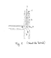
- FIG. 1 shows a known embodiment of the described temperature measuring sleeve, which is designated by 1.
- the pipe piece is a T-piece 4 with a long leg for receiving the temperature measuring sleeve 1.
- the temperature measuring sleeve also referred to as a pressure sleeve, has a plug-in tube 2 for the temperature sensor.
- the nozzle 3 or long leg is expanded to accommodate the pressure sleeve.
- the possible directions of flow of the medium 5 are indicated by a double arrow.
- the construction shown leads to a poor flow control due to the flow resistance and flow diversion.
- the temperature measuring sleeve 1 is screwed into a large-volume standard socket 3 (long leg of the T-piece 4). Overall, this results in a large dimension. Due to the large free lengths occurring certain minimum material thicknesses of the temperature measuring sleeve 1 on the one hand and the nozzle 3 on the other hand to avoid vibrations due to the inflowing medium 5 are necessary. As a further disadvantage remains the already mentioned relatively high minimum wall thickness of the cylindrical tapered to the peak temperature measuring sleeve. 1
- Object of the present invention is therefore to provide an improved temperature measuring device, which allows a fast and unadulterated measurement of the temperature of the flowing through a piece of pipe medium, in particular without the flow dynamics stronger than absolutely necessary to negatively influence and thus to produce a high flow pressure loss.
- the invention proposes to solve the problem, a temperature measuring device of the type mentioned, in which the temperature measuring sleeve protrudes partially into the pipe section, wherein the wall thickness of at least the projecting into the pipe section of the temperature measuring sleeve is less than that of the pipe section, the wall thickness and / or the outer diameter of the temperature measuring sleeve in a predetermined area around the temperature sensor around is reduced again.
- the invention further relates to the corresponding temperature measuring sleeve and the corresponding pipe piece, which is designed as a pipe forming component for receiving the temperature measuring sleeve.
- the invention relates to the use of a temperature measuring device according to the invention for measuring the temperature of hydrogen flowing through the pipe section. Further embodiments of the invention will become apparent from the respective dependent claims and the description below.
- the temperature measuring device has a temperature measuring sleeve, which compared to the pipe section, in which the medium whose temperature is to be measured flows, has a smaller wall thickness.
- the temperature measuring sleeve is usually designed so that the outer diameter is smaller, equal or for connection reasons, slightly larger than the inner diameter of the pipe section.
- the thinness of the temperature measuring sleeve allows a small outer diameter of the temperature sleeve, which is smaller in particular equal to the inner diameter of the pipe section, and thus a total of a small size of the temperature measuring device.
- the area of the again reduced wall thickness and / or the outer diameter in particular at the top of the temperature measuring sleeve. It is sufficient if this reduced in its wall thickness and / or outer diameter area, in particular so the tip of the temperature measuring sleeve projects into the interior of the pipe section to measure there the temperature of the medium.
- a short free tip of the temperature sleeve which projects into the interior of the tube.
- the wall thickness of the short free tip can be reduced to the minimum required wall thickness, which depends on the strength of the selected material and the operating conditions. For reasons of flow mechanics and heat transfer, a ratio of the outer diameter of the tip to the inner diameter of the pipe section should be less than or equal to 0.75.
- the temperature measuring sleeve is high-pressure resistant and / or made of high-strength material, which leads to a further reduction of the minimum necessary wall thickness of the temperature sleeve and thus the overall diameter of the temperature sleeve.
- the temperature measuring sleeve can be advantageously designed with a smaller outer diameter with the same sensor thickness d s than that of the pipe section, in particular as the wall thickness of the pipe section. This allows the introduction of the temperature measuring sleeve in pipes with smaller inner diameters than previously possible.
- the temperature measuring sleeve extends through the wall of the pipe section into a region around the axis of the pipe section into the interior desselbigen.
- the tip of the temperature measuring sleeve or the center of the region of the temperature measuring sleeve which is reduced again in its wall thickness can extend as far as the axis or essentially up to the axis of the pipeline system.
- the longitudinal axis is meant.
- the temperature measuring sleeve thus does not fill large areas of the interior of the tube, but protrudes with its tip, starting from the inner wall of the tube, a small distance, preferably into the middle of the interior. This leads to a stable arrangement, which also affects the flow as little as possible and has a low flow pressure loss.
- the axis of the in particular substantially cylindrical temperature measuring sleeve is at an acute angle to said axis of the pipe section with respect to the flow direction of the medium.
- the tip of the temperature measuring sleeve is thus flowed through by the medium at an acute angle. If the tip is located approximately in the center of the tube, this guarantees an optimal temperature measurement.
- the invention also relates to a temperature measuring sleeve, which can be introduced into a piece of pipe, having the features as described above in connection with the temperature measuring device according to the invention.
- the temperature measuring sleeve is fixed in a suitably formed counterpart in the pipe section, e.g. via clamping ring connection, preferably screwed and / or welded tight
- the invention also relates to a piece of pipe of a temperature measuring device according to the invention described above, wherein this piece of pipe is formed as a pipe forming component for receiving a temperature measuring sleeve according to the invention.
- the pipe forming component is also referred to as a receiving fitting. It is a component that is inserted into a pipeline in which flows the medium whose temperature is to be measured. It is useful if a flange is provided for receiving the temperature measuring sleeve in the pipe molding component, said flange is preferably designed in one piece with the mold component.
- the flange has an opening for introducing the temperature measuring sleeve into the interior of the molded component. If the axis of the temperature measuring sleeve is at an angle to the axis of the pipe section or of the mold component, the flange opening is expediently oriented accordingly.
- the inner diameter of the pipe-forming component is made larger in an environment of the flange than outside of this environment.
- this environment of the flange can be over most of the length in the Inner space of the pipe forming component so that only the end pieces of the pipe forming component have the smaller inner diameter.
- the temperature measuring device is particularly well suited for measuring the temperature of hydrogen flowing through the pipe section or the pipe forming component.
- the invention in addition to the use of the invention in the high-pressure range, it is also particularly well suited for temperature measurements in the low-pressure range and in the field of use of media with high density requirements (toxic, reactive, inflammatory media, foodstuffs, pharmaceutical products), especially if the need for rapid and accurate temperature measurement and / or or the changeability of the temperature sensor without process effect exists.
- FIG. 1 was already explained in the introduction to the description.
- FIGS. 2 to 4 are described comprehensively; like reference numerals indicate like elements.
- FIG. 2 shows a temperature measuring device 30 with a pipe section 11 and a temperature measuring sleeve 10.
- the tube interior 15 of the pipe section 11 is flowed through in the flow direction 17 by a medium 5, such as hydrogen.
- the longitudinal axis of the pipe section 11 is denoted by 16.
- the temperature measuring sleeve 10 is inserted with its front part in a flange 18 (welded here).
- the seal weld is designated 20.
- a front part of the temperature measuring sleeve 10 protrudes into the tube interior 15.
- the tip of the temperature measuring sleeve 10 is denoted by 13. It lies completely inside the pipe 15.
- a temperature sensor (not shown) is arranged inside the temperature measuring sleeve 10.
- pipe piece 11 may be a pipe forming component 14, also referred to as a receiving fitting act, as in FIG. 3 is shown.
- the pipe forming member 14 is inserted into the pipe in which the medium flows.
- the component 14 has a flange 18, which in turn has an opening 19 for receiving the temperature measuring sleeve 10.
- the flange 18 is preferably designed in one piece with the mold component 14. The flow direction of the medium is again denoted by 17.
- FIG. 4 shows the temperature measuring sleeve FIG. 2 in detail.
- the front region of the temperature measuring sleeve 10 with its tip 13 is visible FIG. 4
- the diameter of the temperature measuring sleeve 10 can be seen and with the diameters of the pipe section 11 from FIG. 2 comparable.
- the outer diameter of the temperature measuring sleeve 10 is less in its front region, equal to or not significantly larger than the inner diameter of the pipe section 11.
- a predetermined region 12 around the top of Temperature sensor around are the diameter and wall thickness, as out FIG. 4 seen, again reduced.
- the further reduced in its wall thickness region 12 protrudes, as from FIG. 2
- the temperature measuring sleeve 10 is also designed with a smaller outer diameter than that of the pipe section 11. This allows the introduction of the temperature measuring sleeve 10 in tubes with very small inner diameters.
- the axis of the temperature measuring sleeve 10 includes with the axis 16 of the pipe section 11 with respect to the flow direction 17 an acute angle, the tip 12 of the temperature measuring sleeve 10 extends approximately to the longitudinal axis 16. This allows accurate temperature measurement while having little influence on the flow dynamics.
- FIG. 2 is also apparent that the inner diameter D of the pipe section 11 and the pipe molding component 14 (see. FIG. 3 ) in an environment U of the flange 18 is exemplified larger than outside this environment at the end pieces of the pipe section 11.
- flow rate was optimized to heat transfer to the process requirement.
- gaseous and liquefied gases e.g. Hydrogen and helium
- a pressure of up to 1000 bar In transport, trailers are operated up to 500 bar.
- H2 refueling stations In the automotive industry, H2 refueling stations are being built for refueling up to 700 bar. Compressors up to 1000 bar are used for compression in the gaseous / liquid medium state.
- Typical pipe inside diameters are from 5 mm to 25 mm.
- the measurement of the temperature of the medium serves to determine the maximum filling pressure of the trailer / automotive.
- a fast and unadulterated temperature indicator is essential for correct and safe operation.
- the measuring range of Temperature measurement is in the range of 4 Kelvin to 373 Kelvin. At a temperature measurement of 1000 bar, DN 15, the pipe wall thickness of the piece 11 is 5.5 mm and the pipe wall thickness of the area 12 of the tip is 1.6 mm.
Landscapes
- Physics & Mathematics (AREA)
- General Physics & Mathematics (AREA)
- Measuring Temperature Or Quantity Of Heat (AREA)
Applications Claiming Priority (1)
| Application Number | Priority Date | Filing Date | Title |
|---|---|---|---|
| DE102012012740.5A DE102012012740A1 (de) | 2012-06-26 | 2012-06-26 | Temperaturmesseinrichtung mit Temperaturmesshülse zur Messung der Temperatur eines fließenden Mediums |
Publications (2)
| Publication Number | Publication Date |
|---|---|
| EP2679968A2 true EP2679968A2 (fr) | 2014-01-01 |
| EP2679968A3 EP2679968A3 (fr) | 2017-09-13 |
Family
ID=48625688
Family Applications (1)
| Application Number | Title | Priority Date | Filing Date |
|---|---|---|---|
| EP13002935.8A Withdrawn EP2679968A3 (fr) | 2012-06-26 | 2013-06-06 | Dispositif de mesure de température doté d'une souille de mesure de température pour la mesure de la température d'un produit liquide |
Country Status (4)
| Country | Link |
|---|---|
| US (1) | US20130343427A1 (fr) |
| EP (1) | EP2679968A3 (fr) |
| JP (1) | JP2014006260A (fr) |
| DE (1) | DE102012012740A1 (fr) |
Cited By (2)
| Publication number | Priority date | Publication date | Assignee | Title |
|---|---|---|---|---|
| EP3974793A1 (fr) * | 2020-09-25 | 2022-03-30 | L'air Liquide, Société Anonyme Pour L'Étude Et L'exploitation Des Procédés Georges Claude | Dispositif de mesure permettant de mesurer des profils de température axiaux dans un tube de réacteur |
| US20230296450A1 (en) * | 2020-08-26 | 2023-09-21 | Nifco Inc. | Temperature sensor and method for manufacturing temperature sensor |
Families Citing this family (14)
| Publication number | Priority date | Publication date | Assignee | Title |
|---|---|---|---|---|
| DE102014111985A1 (de) * | 2014-08-21 | 2016-02-25 | Endress + Hauser Wetzer Gmbh + Co. Kg | Verfahren zur Herstellung eines Messrohrs |
| US10115981B2 (en) * | 2015-09-25 | 2018-10-30 | Honda Motor Co., Ltd. | Fuel cell stack |
| JP6420801B2 (ja) * | 2015-09-25 | 2018-11-07 | 本田技研工業株式会社 | 燃料電池スタック |
| DE102015117367A1 (de) * | 2015-10-13 | 2017-04-13 | Technische Universität Dresden | Anschlusseinrichtung für einen Messfühler |
| CN106679831B (zh) * | 2016-12-13 | 2019-01-22 | 中国能源建设集团广东省电力设计研究院有限公司 | 管道内流体介质温度测量装置 |
| CN107991536B (zh) * | 2017-11-03 | 2023-06-13 | 国家电网公司 | 一种频域介电响应测试的温度校正方法及设备 |
| CN108955742A (zh) * | 2018-08-21 | 2018-12-07 | 宁波神通模塑有限公司 | 一种管道传感器固定结构 |
| CN113267266B (zh) * | 2021-07-21 | 2021-09-24 | 东营金昱技术开发有限公司 | 一种具有快速散热功能的防水型温度变送器 |
| CN113655830B (zh) * | 2021-08-30 | 2022-12-02 | 安徽工程大学 | 一种适用于电气自动化设备的温度报警装置 |
| CN113959594A (zh) * | 2021-09-24 | 2022-01-21 | 浙江恒成硬质合金有限公司 | 一种用于测量流动水体温度的测温装置 |
| JP2023088770A (ja) * | 2021-12-15 | 2023-06-27 | 横河電機株式会社 | 流路装置 |
| CN114414094B (zh) * | 2022-03-28 | 2022-06-17 | 四川省郫县豆瓣股份有限公司 | 一种高精度温度测量装置及其测量方法 |
| CN116989907B (zh) * | 2023-09-25 | 2023-12-12 | 常州恒盾机械科技有限公司 | 一种矿用测温的无线测温传感器防护结构 |
| CN118817096B (zh) * | 2024-09-13 | 2025-01-03 | 纳狮新材料有限公司杭州分公司 | 一种真空室内实时检测温度的装置 |
Family Cites Families (10)
| Publication number | Priority date | Publication date | Assignee | Title |
|---|---|---|---|---|
| US2981106A (en) * | 1957-10-08 | 1961-04-25 | Lewis Eng Co | Pyrometer bulb |
| US3081631A (en) * | 1958-11-18 | 1963-03-19 | Gilbert Associates | Thermometer well for pipes |
| GB2048474A (en) * | 1979-02-23 | 1980-12-10 | Ici Ltd | Thermometer mounting |
| GB2272058B (en) * | 1992-10-30 | 1997-01-29 | Schlumberger Ind Ltd | Thermocouple probe |
| US6390670B1 (en) * | 1999-08-06 | 2002-05-21 | Pgi International Ltd. | Temperature sensing device for metering fluids |
| JP3787569B2 (ja) * | 2004-06-30 | 2006-06-21 | 日本特殊陶業株式会社 | 温度センサ |
| US7581879B2 (en) * | 2004-06-30 | 2009-09-01 | Ngk Spark Plug Co., Ltd. | Temperature sensor |
| JP4620400B2 (ja) * | 2004-07-16 | 2011-01-26 | 日本特殊陶業株式会社 | 温度センサ、温度センサの製造方法 |
| DE102009056699B4 (de) * | 2009-12-02 | 2015-04-30 | Abb Technology Ag | Autonomer Temperaturtransmitter |
| US20110150034A1 (en) * | 2009-12-23 | 2011-06-23 | Thermo Fisher Scientific | Sanitary clean in place thermowell |
-
2012
- 2012-06-26 DE DE102012012740.5A patent/DE102012012740A1/de not_active Withdrawn
-
2013
- 2013-06-06 EP EP13002935.8A patent/EP2679968A3/fr not_active Withdrawn
- 2013-06-25 US US13/925,907 patent/US20130343427A1/en not_active Abandoned
- 2013-06-26 JP JP2013133412A patent/JP2014006260A/ja active Pending
Non-Patent Citations (1)
| Title |
|---|
| None |
Cited By (2)
| Publication number | Priority date | Publication date | Assignee | Title |
|---|---|---|---|---|
| US20230296450A1 (en) * | 2020-08-26 | 2023-09-21 | Nifco Inc. | Temperature sensor and method for manufacturing temperature sensor |
| EP3974793A1 (fr) * | 2020-09-25 | 2022-03-30 | L'air Liquide, Société Anonyme Pour L'Étude Et L'exploitation Des Procédés Georges Claude | Dispositif de mesure permettant de mesurer des profils de température axiaux dans un tube de réacteur |
Also Published As
| Publication number | Publication date |
|---|---|
| JP2014006260A (ja) | 2014-01-16 |
| EP2679968A3 (fr) | 2017-09-13 |
| DE102012012740A1 (de) | 2014-01-02 |
| US20130343427A1 (en) | 2013-12-26 |
Similar Documents
| Publication | Publication Date | Title |
|---|---|---|
| EP2679968A2 (fr) | Dispositif de mesure de température doté d'une souille de mesure de température pour la mesure de la température d'un produit liquide | |
| EP2710360B1 (fr) | Dispositif pour recevoir et/ou conduire un milieu liquide ou gazeux et procédé pour produire un tel dispositif | |
| DE102017001049A1 (de) | Wirkdruckgeber | |
| EP3387405B1 (fr) | Dispositif de mesure non intrusive de la pression d'un fluide | |
| EP3452236A1 (fr) | Procédé de fabrication d'un élément de raccordement tubulaire cintré | |
| EP3191803A1 (fr) | Tube servant à mesurer une pression différentielle d'un fluide parcourant le tube | |
| EP4179243A1 (fr) | Dispositif de raccordement d'un élément de tuyau de transport de gaz et procédé de raccordement d'un élément de tuyau de transport de gaz | |
| DE102010043781A1 (de) | Messgerät | |
| DE102013019608B4 (de) | Messelement und Verfahren und Rohrfedermanometer | |
| DE102018107017A1 (de) | Muffe mit Sensoranschluss und Verfahren zum Anbringen eines Sensors an einer Rohrleitung | |
| EP2251582B1 (fr) | Système de séparation de conduites à double tuyau | |
| EP1819953B1 (fr) | Procede de fabrication d'un composant supportant une pression | |
| DE102014016975A1 (de) | Vorrichtung zum Verbinden eines gasführenden Leitungselements mit einem Bauteil | |
| DE102010029343A1 (de) | Adapter zum Anschluss eines flanschlossen Durchflussmessgeräts an eine Rohrleitung | |
| DE102011117137A1 (de) | Verfahren und Anordnung zum Anschließen eines fexiblen Leitungselements aus Metall | |
| DE102017210086B4 (de) | Anschlussvorrichtung | |
| DE10227373B4 (de) | Rohrförmige Staudrucksonde | |
| DE102014106927A1 (de) | Messgerät, insbesondere Durchflussmessgerät, und Verfahren zur zur Herstellung eines Messrohres für ein Messgerät | |
| EP4409258B1 (fr) | Technique d'essai pour un échantillon d'essai tubulaire faisant intervenir une pression de liquide | |
| DE4421272A1 (de) | Doppeleinlaßsystem für die Messung der Isotopenzusammensetzung gasförmiger Substanzen sowie Verfahren zum Betreiben eines solchen Systems | |
| EP4191111B1 (fr) | Couplage de guidage de média et guidage de média | |
| EP3280943B1 (fr) | Dispositif permettant de relier une conduite de raccordement à une conduite rénovée | |
| DE102022003875B4 (de) | Druck-Armatur für Materialströme, Verfahren zum Betreiben von Druckarmaturen sowie Verwendung | |
| EP2295841A1 (fr) | Procédé de connexion de tuyaux et connexions de tuyaux | |
| DE4318872A1 (de) | Doppelrohr für eine pneumatische Förderung |
Legal Events
| Date | Code | Title | Description |
|---|---|---|---|
| PUAI | Public reference made under article 153(3) epc to a published international application that has entered the european phase |
Free format text: ORIGINAL CODE: 0009012 |
|
| AK | Designated contracting states |
Kind code of ref document: A2 Designated state(s): AL AT BE BG CH CY CZ DE DK EE ES FI FR GB GR HR HU IE IS IT LI LT LU LV MC MK MT NL NO PL PT RO RS SE SI SK SM TR |
|
| AX | Request for extension of the european patent |
Extension state: BA ME |
|
| PUAL | Search report despatched |
Free format text: ORIGINAL CODE: 0009013 |
|
| AK | Designated contracting states |
Kind code of ref document: A3 Designated state(s): AL AT BE BG CH CY CZ DE DK EE ES FI FR GB GR HR HU IE IS IT LI LT LU LV MC MK MT NL NO PL PT RO RS SE SI SK SM TR |
|
| AX | Request for extension of the european patent |
Extension state: BA ME |
|
| RIC1 | Information provided on ipc code assigned before grant |
Ipc: G01K 1/14 20060101AFI20170807BHEP Ipc: G01K 13/02 20060101ALI20170807BHEP |
|
| STAA | Information on the status of an ep patent application or granted ep patent |
Free format text: STATUS: THE APPLICATION IS DEEMED TO BE WITHDRAWN |
|
| 18D | Application deemed to be withdrawn |
Effective date: 20180314 |