EP2680907B1 - Bouchon pour seringue de poudre et seringue de poudre - Google Patents
Bouchon pour seringue de poudre et seringue de poudre Download PDFInfo
- Publication number
- EP2680907B1 EP2680907B1 EP12707475.5A EP12707475A EP2680907B1 EP 2680907 B1 EP2680907 B1 EP 2680907B1 EP 12707475 A EP12707475 A EP 12707475A EP 2680907 B1 EP2680907 B1 EP 2680907B1
- Authority
- EP
- European Patent Office
- Prior art keywords
- channel
- closure piece
- powder
- closure
- powder syringe
- Prior art date
- Legal status (The legal status is an assumption and is not a legal conclusion. Google has not performed a legal analysis and makes no representation as to the accuracy of the status listed.)
- Active
Links
Images




Classifications
-
- A—HUMAN NECESSITIES
- A61—MEDICAL OR VETERINARY SCIENCE; HYGIENE
- A61M—DEVICES FOR INTRODUCING MEDIA INTO, OR ONTO, THE BODY; DEVICES FOR TRANSDUCING BODY MEDIA OR FOR TAKING MEDIA FROM THE BODY; DEVICES FOR PRODUCING OR ENDING SLEEP OR STUPOR
- A61M5/00—Devices for bringing media into the body in a subcutaneous, intra-vascular or intramuscular way; Accessories therefor, e.g. filling or cleaning devices, arm-rests
- A61M5/178—Syringes
- A61M5/31—Details
-
- A—HUMAN NECESSITIES
- A61—MEDICAL OR VETERINARY SCIENCE; HYGIENE
- A61M—DEVICES FOR INTRODUCING MEDIA INTO, OR ONTO, THE BODY; DEVICES FOR TRANSDUCING BODY MEDIA OR FOR TAKING MEDIA FROM THE BODY; DEVICES FOR PRODUCING OR ENDING SLEEP OR STUPOR
- A61M5/00—Devices for bringing media into the body in a subcutaneous, intra-vascular or intramuscular way; Accessories therefor, e.g. filling or cleaning devices, arm-rests
- A61M5/178—Syringes
- A61M5/28—Syringe ampoules or carpules, i.e. ampoules or carpules provided with a needle
- A61M5/284—Syringe ampoules or carpules, i.e. ampoules or carpules provided with a needle comprising means for injection of two or more media, e.g. by mixing
-
- A—HUMAN NECESSITIES
- A61—MEDICAL OR VETERINARY SCIENCE; HYGIENE
- A61M—DEVICES FOR INTRODUCING MEDIA INTO, OR ONTO, THE BODY; DEVICES FOR TRANSDUCING BODY MEDIA OR FOR TAKING MEDIA FROM THE BODY; DEVICES FOR PRODUCING OR ENDING SLEEP OR STUPOR
- A61M5/00—Devices for bringing media into the body in a subcutaneous, intra-vascular or intramuscular way; Accessories therefor, e.g. filling or cleaning devices, arm-rests
- A61M5/178—Syringes
- A61M5/28—Syringe ampoules or carpules, i.e. ampoules or carpules provided with a needle
- A61M5/285—Syringe ampoules or carpules, i.e. ampoules or carpules provided with a needle with sealing means to be broken or opened
- A61M5/286—Syringe ampoules or carpules, i.e. ampoules or carpules provided with a needle with sealing means to be broken or opened upon internal pressure increase, e.g. pierced or burst
-
- A—HUMAN NECESSITIES
- A61—MEDICAL OR VETERINARY SCIENCE; HYGIENE
- A61J—CONTAINERS SPECIALLY ADAPTED FOR MEDICAL OR PHARMACEUTICAL PURPOSES; DEVICES OR METHODS SPECIALLY ADAPTED FOR BRINGING PHARMACEUTICAL PRODUCTS INTO PARTICULAR PHYSICAL OR ADMINISTERING FORMS; DEVICES FOR ADMINISTERING FOOD OR MEDICINES ORALLY; BABY COMFORTERS; DEVICES FOR RECEIVING SPITTLE
- A61J1/00—Containers specially adapted for medical or pharmaceutical purposes
- A61J1/14—Details; Accessories therefor
- A61J1/1406—Septums, pierceable membranes
-
- A—HUMAN NECESSITIES
- A61—MEDICAL OR VETERINARY SCIENCE; HYGIENE
- A61J—CONTAINERS SPECIALLY ADAPTED FOR MEDICAL OR PHARMACEUTICAL PURPOSES; DEVICES OR METHODS SPECIALLY ADAPTED FOR BRINGING PHARMACEUTICAL PRODUCTS INTO PARTICULAR PHYSICAL OR ADMINISTERING FORMS; DEVICES FOR ADMINISTERING FOOD OR MEDICINES ORALLY; BABY COMFORTERS; DEVICES FOR RECEIVING SPITTLE
- A61J1/00—Containers specially adapted for medical or pharmaceutical purposes
- A61J1/14—Details; Accessories therefor
- A61J1/20—Arrangements for transferring or mixing fluids, e.g. from vial to syringe
- A61J1/2003—Accessories used in combination with means for transfer or mixing of fluids, e.g. for activating fluid flow, separating fluids, filtering fluid or venting
- A61J1/202—Separating means
- A61J1/2041—Separating means having removable plugs
-
- A—HUMAN NECESSITIES
- A61—MEDICAL OR VETERINARY SCIENCE; HYGIENE
- A61M—DEVICES FOR INTRODUCING MEDIA INTO, OR ONTO, THE BODY; DEVICES FOR TRANSDUCING BODY MEDIA OR FOR TAKING MEDIA FROM THE BODY; DEVICES FOR PRODUCING OR ENDING SLEEP OR STUPOR
- A61M5/00—Devices for bringing media into the body in a subcutaneous, intra-vascular or intramuscular way; Accessories therefor, e.g. filling or cleaning devices, arm-rests
- A61M5/178—Syringes
- A61M5/28—Syringe ampoules or carpules, i.e. ampoules or carpules provided with a needle
- A61M5/285—Syringe ampoules or carpules, i.e. ampoules or carpules provided with a needle with sealing means to be broken or opened
- A61M5/286—Syringe ampoules or carpules, i.e. ampoules or carpules provided with a needle with sealing means to be broken or opened upon internal pressure increase, e.g. pierced or burst
- A61M2005/287—Syringe ampoules or carpules, i.e. ampoules or carpules provided with a needle with sealing means to be broken or opened upon internal pressure increase, e.g. pierced or burst by displacing occluding plugs
-
- A—HUMAN NECESSITIES
- A61—MEDICAL OR VETERINARY SCIENCE; HYGIENE
- A61M—DEVICES FOR INTRODUCING MEDIA INTO, OR ONTO, THE BODY; DEVICES FOR TRANSDUCING BODY MEDIA OR FOR TAKING MEDIA FROM THE BODY; DEVICES FOR PRODUCING OR ENDING SLEEP OR STUPOR
- A61M5/00—Devices for bringing media into the body in a subcutaneous, intra-vascular or intramuscular way; Accessories therefor, e.g. filling or cleaning devices, arm-rests
- A61M5/178—Syringes
- A61M5/31—Details
- A61M2005/3103—Leak prevention means for distal end of syringes, i.e. syringe end for mounting a needle
- A61M2005/3104—Caps for syringes without needle
-
- A—HUMAN NECESSITIES
- A61—MEDICAL OR VETERINARY SCIENCE; HYGIENE
- A61M—DEVICES FOR INTRODUCING MEDIA INTO, OR ONTO, THE BODY; DEVICES FOR TRANSDUCING BODY MEDIA OR FOR TAKING MEDIA FROM THE BODY; DEVICES FOR PRODUCING OR ENDING SLEEP OR STUPOR
- A61M5/00—Devices for bringing media into the body in a subcutaneous, intra-vascular or intramuscular way; Accessories therefor, e.g. filling or cleaning devices, arm-rests
- A61M5/178—Syringes
- A61M5/31—Details
- A61M2005/3103—Leak prevention means for distal end of syringes, i.e. syringe end for mounting a needle
- A61M2005/3106—Plugs for syringes without needle
-
- A—HUMAN NECESSITIES
- A61—MEDICAL OR VETERINARY SCIENCE; HYGIENE
- A61M—DEVICES FOR INTRODUCING MEDIA INTO, OR ONTO, THE BODY; DEVICES FOR TRANSDUCING BODY MEDIA OR FOR TAKING MEDIA FROM THE BODY; DEVICES FOR PRODUCING OR ENDING SLEEP OR STUPOR
- A61M5/00—Devices for bringing media into the body in a subcutaneous, intra-vascular or intramuscular way; Accessories therefor, e.g. filling or cleaning devices, arm-rests
- A61M5/178—Syringes
- A61M5/31—Details
- A61M2005/3117—Means preventing contamination of the medicament compartment of a syringe
- A61M2005/3118—Means preventing contamination of the medicament compartment of a syringe via the distal end of a syringe, i.e. syringe end for mounting a needle cannula
-
- A—HUMAN NECESSITIES
- A61—MEDICAL OR VETERINARY SCIENCE; HYGIENE
- A61M—DEVICES FOR INTRODUCING MEDIA INTO, OR ONTO, THE BODY; DEVICES FOR TRANSDUCING BODY MEDIA OR FOR TAKING MEDIA FROM THE BODY; DEVICES FOR PRODUCING OR ENDING SLEEP OR STUPOR
- A61M5/00—Devices for bringing media into the body in a subcutaneous, intra-vascular or intramuscular way; Accessories therefor, e.g. filling or cleaning devices, arm-rests
- A61M5/178—Syringes
- A61M5/31—Details
- A61M2005/3117—Means preventing contamination of the medicament compartment of a syringe
- A61M2005/3118—Means preventing contamination of the medicament compartment of a syringe via the distal end of a syringe, i.e. syringe end for mounting a needle cannula
- A61M2005/312—Means preventing contamination of the medicament compartment of a syringe via the distal end of a syringe, i.e. syringe end for mounting a needle cannula comprising sealing means, e.g. severable caps, to be removed prior to injection by, e.g. tearing or twisting
-
- A—HUMAN NECESSITIES
- A61—MEDICAL OR VETERINARY SCIENCE; HYGIENE
- A61M—DEVICES FOR INTRODUCING MEDIA INTO, OR ONTO, THE BODY; DEVICES FOR TRANSDUCING BODY MEDIA OR FOR TAKING MEDIA FROM THE BODY; DEVICES FOR PRODUCING OR ENDING SLEEP OR STUPOR
- A61M5/00—Devices for bringing media into the body in a subcutaneous, intra-vascular or intramuscular way; Accessories therefor, e.g. filling or cleaning devices, arm-rests
- A61M5/178—Syringes
- A61M5/31—Details
- A61M5/32—Needles; Details of needles pertaining to their connection with syringe or hub; Accessories for bringing the needle into, or holding the needle on, the body; Devices for protection of needles
- A61M5/34—Constructions for connecting the needle, e.g. to syringe nozzle or needle hub
- A61M5/344—Constructions for connecting the needle, e.g. to syringe nozzle or needle hub using additional parts, e.g. clamping rings or collets
- A61M5/345—Adaptors positioned between needle hub and syringe nozzle
-
- A—HUMAN NECESSITIES
- A61—MEDICAL OR VETERINARY SCIENCE; HYGIENE
- A61M—DEVICES FOR INTRODUCING MEDIA INTO, OR ONTO, THE BODY; DEVICES FOR TRANSDUCING BODY MEDIA OR FOR TAKING MEDIA FROM THE BODY; DEVICES FOR PRODUCING OR ENDING SLEEP OR STUPOR
- A61M5/00—Devices for bringing media into the body in a subcutaneous, intra-vascular or intramuscular way; Accessories therefor, e.g. filling or cleaning devices, arm-rests
- A61M5/178—Syringes
- A61M5/31—Details
- A61M5/32—Needles; Details of needles pertaining to their connection with syringe or hub; Accessories for bringing the needle into, or holding the needle on, the body; Devices for protection of needles
- A61M5/34—Constructions for connecting the needle, e.g. to syringe nozzle or needle hub
- A61M5/347—Constructions for connecting the needle, e.g. to syringe nozzle or needle hub rotatable, e.g. bayonet or screw
Definitions
- the invention relates to a closure for a powder syringe according to the preamble of claim 1 and a powder syringe according to the preamble of claim 13.
- Closures and powder spraying of the type discussed here are known. Preference is given to using dual-chamber systems as powder syringes, which have a proximal chamber and a distal chamber.
- the proximal chamber typically comprises a liquid solvent and is separated from the distal chamber by a center plug having a solvent-soluble material. This may be a powder that has a trickle tendency.
- Known closures have a channel that is in fluid communication with the distal chamber on the one hand, and that can be fluidly connected to a cannula or syringe needle placed on the closure on the other hand. It is possible for powder to reach the region of the channel provided in the closure or into the channel itself.
- the object of the invention is therefore to provide a closure for a powder syringe and a powder syringe, which does not have the disadvantages described.
- the object is achieved by providing a closure with the features of claim 1.
- the closure for a powder syringe comprises a base body and a sealing element which is arranged on the base body so that it sealingly abuts a distal opening of a powder tip when the closure is arranged on the powder syringe in its closing position.
- the closure also has a channel which passes through the base body and the sealing element. This has a proximal and a distal end.
- the closure is characterized by a retaining element, which is designed and / or arranged so that penetration of powder from a chamber of the powder syringe into the channel is largely prevented before activation of the powder syringe when the closure is arranged in its closing position on the powder syringe is.
- the retaining element is either designed so that it prevents penetration of the powdered material into the channel of the closure when it is arranged in its Verschdorfposition, or it can - possibly separated from the remaining elements of the closure - be arranged so that it Penetration of the powder into the channel prevented.
- the retaining element is arranged so that residual volumes in which agglomeration is possible, minimized or particularly preferably completely avoided.
- the retaining element can also be designed accordingly at the same time and be arranged accordingly.
- a closure comprising a closure cap for closing the distal end of the channel, the closure cap having a rod-shaped projection. This passes through the channel, wherein the retaining element is provided on it. The rod-shaped projection virtually closes the channel. This has the advantage that at a distance of the cap for activating the powder syringe at the same time the channel is released, without the need for further action. In addition, in a closure, which already includes a cap, no further elements necessary.
- the retaining element is designed as a preferably slotted membrane.
- the membrane can be burst open by the pressure forces built up when activating the syringe or for delivering the contents of the syringe to a patient, be shaped and pierced with the aid of a needle-shaped device or widened in the area of a slit to release the channel.
- the retaining element is formed as displaceable along the channel element. This is preferably arranged in the storage state of the syringe at the proximal end of the channel and closes it. To activate the powder syringe, the element can be displaced along the channel to its distal end, where it finally exits the channel and thus releases it.
- the retaining element comprises a soluble substance.
- the retention element comprises a lyophilized substance. This can be solved by activating the syringe by a solvent, so that the channel is released.
- the retaining element comprises a closure disc, which is designed so that it can sealingly abut against a constriction of a powder syringe. In this way it can prevent the penetration of powder into the channel.
- the closure disk can be soaked in particular in the region of the constriction of the powder syringe so that no powder can penetrate into the channel before activation of the powder syringe. Upon activation of the powder syringe, the closure disc is displaced away from the restriction so that a fluid path to the channel is released.
- a powder syringe with the features of claim 13. This has a distal opening and is characterized in that it carries a closure according to one of claims 1 to 12. Due to the Closure, which includes a retaining element for the powder, the powder syringe can be stored long and in any position without the risk of agglomeration of powder in the channel, because the powder is retained by the retaining element.
- the powder syringe is designed as a dual-chamber system.
- a powder syringe having a constriction in the region of its distal end.
- FIG. 1 shows a powder syringe 1, which is provided with a first embodiment of a closure 3.
- the powder syringe 1 has a proximal end 5 and a distal end 7. At the distal end 7, a distal opening 9 is provided. At the proximal end 5, a proximal opening 11 is arranged. In the region of the proximal opening 5, a finger rest 13 is arranged, which has a passage for a piston rod, not shown.
- the powder syringe 1 is formed as a dual-chamber system.
- a middle stopper 15 is preferably introduced through the proximal opening 11 into the interior of the powder syringe 1, which separates a proximal chamber 17 from a distal chamber 19.
- the distal chamber 19 is preferably filled by the distal opening 9.
- a dissolved active ingredient or a combination of dissolved active ingredients in general, a solution can be filled, which is then lyophilized. Thereafter, the distal chamber 19 or the distal opening 9 is closed by the closure 3.
- a lyophilisate cake placed in the distal chamber 19 typically adheres to a wall 21 of the powder syringe 1 so that it is not free to move in the distal chamber 19.
- a pulverulent, soluble substance is filled into the distal chamber 19, it can be distributed freely there.
- the distal chamber 19 is closed with the closure 3.
- the powder can then reach into the region of a channel of the closure 3 and optionally form insoluble agglomerates there. These clog the channel and impair the functionality of the powder syringe 1.
- a solvent can be introduced into the proximal chamber 17, after which it is closed by an end plug 23.
- the end plug 23 preferably has coupling means 25 for coupling to a non-illustrated piston rod.
- the coupling means 25 is an internal thread which can mesh with an external thread provided on the piston rod, not shown.
- a powder 27 is present in the distal chamber 19 of the powder syringe 1 designed here as a dual-chamber system.
- a solvent 29 is preferably present in the proximal chamber 17.
- the powder 27 is preferably soluble in the solvent 29.
- the wall 21 has a radial projection which, viewed in the circumferential direction, extends over only a relatively small angular range and is designed as a bypass 31.
- the End stop 23 is displaced in the direction of the distal end 7 with the help of the piston rod, not shown here, wherein due to the pressure forces formed in the proximal chamber 17 and the center stopper 15 moves in this direction.
- a radial direction is accordingly a direction perpendicular to the longitudinal direction.
- the longitudinal direction is also addressed as an axial direction.
- a circumferential direction extends along a circumferential line about the longitudinal axis of the powder syringe 1.
- the bypass 31 has - seen in the longitudinal direction - an extension which is greater than the axial length of the center plug 15. Therefore, if the center plug 15 moves in the region of the bypass 31, a fluid connection between the proximal chamber 17 and the distal chamber 19th formed over the bypass 31.
- the solvent 29 is then introduced in particular by means of a further displacement of the end plug 23 from the proximal chamber 17 in the distal chamber 19, where it dissolves the powder 27. Finally, a state is reached in which the center plug 15 and the end plug 23 abut each other.
- the solution now present in the distal chamber 19 can be expelled from the powder syringe 1 and preferably injected into a patient.
- the design and operation of such dual-chamber systems is known per se, so that will not be discussed further here.
- the distal opening 9 is preferably widened in comparison to double-chamber systems provided for lyophilisates, because this makes it easier to fill in the powder, while for a solution a smaller diameter suffices.
- the invention is not limited to powder spraying, which are designed as a double-chamber systems.
- the problem that powder present in a chamber of the syringe can agglomerate in a channel of a closure generally results with every powder syringe. Accordingly, the solution proposed here is applicable to any powder syringe. It also turns out that it is not excluded that a lyophilisate present in a distal chamber of a dual-chamber system becomes at least partially powdered during storage and can then clog the channel of a closure.
- the closure proposed here can therefore of course also preferably be used in a dual-chamber system which comprises a lyophilisate in its distal chamber.
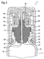
- FIG. 2 shows a detailed view of the embodiment of the closure 3 according to FIG. 1 , Identical and functionally identical elements are provided with the same reference numerals, so that reference is made to the preceding description.
- the closure 3 has a main body 33.
- a sealing element 35 is arranged so that it rests sealingly on the powder syringe 1 at the distal opening 9 of the powder syringe 1 in the closing position of the closure 3 shown here.
- the sealing element 35 is made of an elastic material and is virtually clamped between the wall 21 of the powder syringe 1 and the base body 33 of the closure 3, so that there is a sealing effect.
- an opening region 37 of the powder syringe 1 has an inner contour to which an outer contour of the sealing element 35 is adapted, so that it sealingly abuts in the closing position of the closure 3 along the entire mouth region 37.
- FIG. 2 Some edges of the sealing element 35 with edges of the main body 33 and the wall 21 are shown overlapping. This is merely an artifact of assembly in the technical drawing, in which the sealing element 35 is shown in its uncompressed state between the base body 33 and the wall 21. In reality, the sealing element is pressed together and then lies close to the base body 33 and the wall 21 at. If this state were represented realistically here, the corresponding edges would lie against each other, so that there would be no overlaps.
- the base body 33 has, at its end facing the distal chamber 19, inwardly pointing, radial projections 39, 39 '. With this he grasps behind a flange 41 of the powder syringe 1, which is provided in the mouth region 37 so that in the wall 21, an almost undercut or groove 43 is formed. In this grip the projections 39, 39 'in the Verschierposition of the closure 3 as a kind of locking lugs. Thus, it is possible to introduce forces into the sealing element 35, which press it together and allow its tight abutment in the region of the distal opening 9 or in the mouth region 37. At the same time, the shutter 3 by the projections 39, 39 'held securely on the base body formed by the wall 21 of the powder syringe 1.
- the flange 41 preferably comprises an annular groove which engages around it in the circumferential direction. In this groove, not shown here, the projections 39, 39 'engage latching.
- a further detent position is then formed, as it were, above the detent position of the closure 3, in which the sealing element 35 is not only not compressed, but leaves a gap in the area of the distal opening 9, so that a fluid connection is made from the distal chamber 19 in the surrounding area of the powder syringe 1 exists. It is possible to lyophilize a solution introduced in the distal chamber 19 while the shutter 3 is located in its upper detent position. After completion of the lyophilization process, the closure 3 is then placed in its in FIG. 2 shown locking position in which it sealingly closes the distal chamber 19.
- the closure 3 has a channel 45, which passes through the base body 33 and the sealing element 35.
- the channel 45 has a proximal end 47 and a distal end 49.
- powdered material from the distal chamber 19 via the proximal end 47 can penetrate into the channel 45.
- agglomerates may form, which may be insoluble and affect the functionality of the powder syringe 1.
- the closure 3 has a retaining element 51 which is designed and / or can be arranged such that preferably no powder can penetrate from the distal chamber 19 into the channel 45 before activation of the powder syringe if the closure 3 in FIG his in FIG. 2 shown closing position is arranged on the powder syringe.
- the closure 3 has a closure cap 53 which closes the distal end 49 of the channel 45.
- the closure cap 53 comprises a preferably rod-shaped projection 55. This protrudes through the channel.
- the retaining member 51 is provided on the projection 55.
- the preferably rod-shaped projection 55 with a diameter which is greater than the diameter of the portion of the channel 45 penetrating the sealing element 35.
- the sealing element 35 is then compressed when the projection 55 is inserted into the corresponding channel section, and it is correspondingly close to the same. If the projection 55 then has an extension, as seen in the longitudinal direction, which extends to the proximal end 47, the channel 45 is tightly sealed, so that no powder can penetrate into it.
- the retaining element 51 is formed as a thickening 57 of the rod-shaped projection.
- the thickening 57 is provided at an end of the projection 55 facing the distal chamber 19.
- the projection 55 passes through the entire sealing element 35, so that it protrudes with the thickening 57 at least partially out of the proximal end 47 of the channel 45.
- the sealing element 35 is sealingly against, so that the proximal end 47 is sealed. Thus, no powder can penetrate into the channel 45.
- a retaining element in the form of the thickening 57 is provided on the projection 55, its diameter outside the thickening 57 can be made smaller than corresponds to the inner diameter of the section of the channel 45 in the sealing element 35. As a result, frictional forces are reduced when removing the cap 53.
- the basic body 33 preferably has a projection 59, which serves for coupling with a cannula or syringe needle.
- the projection 59 conical. It is particularly preferably designed as a Luer cone.
- the base body 33 it is possible for the base body 33 to also have a luer thread 61 which surrounds the projection 59 and serves for coupling with dispensing means for dispensing an active substance or a solution.
- a Luer cone and a Luer thread are known, so it will not be discussed further here.
- the closure cap 53 still has a wall portion 63 which encompasses the attachment 59. At its distal end of the chamber 19 facing a - in the circumferential direction - extending radial projection 65 is provided. This is preferably in engagement with the Luer thread 61, so that the closure cap 53 can be screwed into or out of the Luer thread.
- FIG. 3 shows a second embodiment of a closure 3.
- the same and functionally identical elements are provided with the same reference numerals, so that reference is made to the preceding description.
- the retaining element is formed as a membrane 67.
- This can in principle be pierceable, rupturable, in particular by pressure forces aufsprengbar or designed destructible in other ways.
- destructible, in particular puncturable or aufsprengbare membranes have the disadvantage that small particles can be released when opening the membrane and injected into the patient.
- the diaphragm 67 is therefore preferably designed as a slotted membrane. It therefore has at least one slot 69, in the region of which it can be widened due to compressive forces.
- the slot can be urgeformt in a preferably injection-molded membrane, so be generated during spraying. He is preferably also possible to introduce the slot after production in this, for example by cutting, preferably laser cutting.
- the slot in the closed state is so narrow that no powder can penetrate. But it is also possible that only so little powder can penetrate through the slot that agglomeration in the channel 45 is excluded. Such an embodiment is also included in the subject matter of the invention.
- the sealing element 35 - seen in the axial direction - formed shorter than in the embodiment according to FIG. 2 has no contour here, which extends into the mouth region 37 and follows its contour.
- a sealing element which as in FIG. 2 is designed to provide a preferably slotted membrane.
- the sealing element 35 extends in the illustrated embodiment, however, through the entire projection 59 of the body 33. It even overlaps - seen in the axial direction - the projection 59 and forms at its distal end an annular bearing portion 71st
- the closure cap 53 bears here sealingly against the projection 59 with the wall section 63. It only has a short central Projection 73, which protrudes comparatively only over a short distance in the channel 45 and tight against the sealing element 35.
- the material which comprises the main body 33 and therefore also the shoulder 59, or of which they consist, is typically not suitable for a primary contact. This means that a drug must not have any contact with the main body 33, in particular during its storage. Therefore, the closure cap 53 typically has a projection 73 which, viewed in the axial direction, extends at least so far that it seals with the sealing element 35. This avoids that an agent provided in the distal chamber 19 gets in contact with the material of the main body 33.
- the sealing element 35 extends - as in the in FIG. 3 illustrated embodiment - through the entire projection 59 through and even beyond this one annular support portion 71, it is not necessary to provide a long projection 73 on the cap 53. Instead, it is sufficient if this is designed so that it still sealingly engages with the support area 71. It is then ensured that a substance provided in the distal chamber 19 does not come into contact with the material of the main body 33.
- the retaining ring 75 is connected via tear-off webs 77 with a securing cap 79 which engages over and around the closure cap 53.
- the securing cap 79 is separated and removed from the securing ring 75 in the region of the tear-off webs 77. Subsequently, the closure cap 53 can be removed in order to establish a fluid connection of the surroundings of the powder syringe 1 with the channel 45.
- FIG. 4 shows a sectional view of the embodiment according to FIG. 3 along the line AA. Identical and functionally identical elements are provided with the same reference numerals, so that reference is made to the preceding description.
- the base body 33 In the outer region of the retaining ring 75 is shown, which surrounds the base body 33. It is clear here that the base body 33 has a plurality of slots or recesses in the region of the cutting plane and in particular also in the region of the projections 39, 39 ', which extend over a certain area, viewed in the axial direction. By way of example, two slots are designated by the reference numerals 81, 81 'here. Overall, in FIG. 4 eight slots or recesses provided along the circumference of the base body.
- the recesses cause, on the one hand, that the base body 33 in the region of the projections 39, 39 'has sufficient elasticity to be pushed over the flange 41 before the projections 39, 39' engage in the groove 43.
- the recesses are essential when the closure 3 is used together with a dual-chamber system, in the distal chamber 19, a lyophilisate is provided.
- the closure 3 is then preferably located in its upper latching position during lyophilization, in which it the distal Do not close the opening 9 of the dual-chamber system tightly.
- the fluid path through which the solvent evaporating during the freeze-drying process can pass from the distal chamber 19 and the distal opening 9 into the environment of the dual-chamber system then passes through the recesses, in particular also through the slots 81, 81 ', which are exemplarily designated here.
- the membrane 67 is arranged. It has two slots 83, 83 ', which are perpendicular to each other, so that the overall result is a cross-shaped Einschlitzung. It is possible that the membrane 67 has only one slot. Also, more than two slots are possible. If two slots are provided, they must by no means be perpendicular to each other. In principle, any number and geometric arrangement of slots is possible.
- a width of the slots or an opening arranged in the center of the slots 83, 83 'arranged in a crosswise manner here is smaller than an average particle size of the powder which is provided in the distal chamber 19.
- the opening or the slot width is smaller than the smallest grain size of this powder.
- the membrane 67 is formed integrally with the sealing element 35. It is also possible to provide them as a separate element. In this case, it is preferably suitably connected to the sealing element 35. Particularly preferably, the membrane 67 is arranged on the proximal end 47 of the channel 49.
- FIG. 5 shows a third embodiment of a closure 3.
- the retaining element 51 is designed here as a displaceable element along the channel 45.
- the displaceable element is a ball 85. This has a diameter which is greater than the diameter of the portion of the channel 45 which is arranged in the sealing element 35. As a result, the proximal end 47 can be closed by the ball 85. The ball 85 is held by friction in its Verschpidposition.
- the displaceable element may have a different geometry.
- at least one projection on the ball 85 is possible, which extends beyond the proximal end 47 into the distal chamber 19. In this way, the channel 45 can also be closed directly at its proximal end 47.
- a cylindrical element may be provided. This too can be one have corresponding projection. Any other geometry n is possible.
- the displaceable element preferably comprises or consists of glass. It then has the necessary hardness, so that the sealing elements 35 can bear sealingly against him.
- glass is a material suitable for primary contact.
- a retaining means 87 for the displaceable element is provided at the proximal end 47. This prevents the displaceable element from entering the distal chamber 19.
- the holding means 87 is formed as a radial projection of a wall of the channel 45, on which the ball 85 abuts. If the displaceable element has a projection, this can extend through the region of the holding means 87, so that this region is also reliably protected against the penetration of powder from the distal chamber 19. A residual volume of the channel 45, in which optionally agglomeration is still possible, is thus not only minimized but largely avoided or even completely avoided.
- a disadvantage here is that the displaceable element is then either flushed out of the powder syringe 1, in which case it can be injected into a patient in the worst case, or it clogs a cannula or a syringe needle or closes its inlet. It is therefore preferable to provide a retaining means, which retains the displaceable element and at the same time releases a fluid path into an environment of the powder syringe 1.
- Such a retaining means may be provided in a specially designed cannula attachment.
- this is a relatively complicated and expensive solution, because then the closure 3 or the powder syringe 1 can not be used with conventional cannulas or syringe needles.
- FIG. 6 shows with regard to FIG. 5 slightly modified embodiment of the closure 3 in the activated state.
- a retaining means 89 for the displaceable element is provided in the region of the distal end 49 of the channel 45.
- a cannula 91 is arranged on the projection 59.
- This preferably comprises an inner cone, which can cooperate with the preferably conical projection 59 so that a tight connection of the powder syringe 1 to the cannula 91 is ensured.
- the retaining means 89 absorbs virtually the displaceable element.
- a fluid path from the channel 45 to the cannula 91 remains.
- an injection solution can flow around the displaceable element designed here as a ball 85.
- the operation of the restraining means 89 is based on the sectional view of FIG. 7 along the line AA in FIG. 6 explained in more detail. Identical and functionally identical elements are provided with the same reference numerals, so that reference is made to the preceding description.
- the luer thread 61 is shown in the outer area of FIG. 7 . Inwardly, viewed in the radial direction, next follows a wall section of the cannula 91. Next radially inside, the approach 59 is finally shown. Again, this results in an apparent overlap, which results from the fact that the graphic assembly was made with the elements in their disassembled configuration. Expansions or compression of material resulting from the assembly of the various elements were not taken into account here, resulting in seemingly overlapping areas.
- the projection 59 has, in the region of the distal end 49, radial projections 93, 93 ', 93 "' which project radially inwardly into the channel 45 so far that the displaceable element or the ball 85 is retained by them Embodiment - seen in the circumferential direction - three radial projections 93, 93 ', 93 "is provided. Finally, a radial projection is sufficient if it extends radially enough inwardly to retain the ball 85. There are also two or more than three projections possible.
- FIG. 8 shows a fourth embodiment of the shutter 3.
- the retaining element here comprises a soluble substance 97.
- This is selected to be in the same Solvent is soluble, in which the dissolving powder or optionally lyophilisate is soluble, which is present in the distal chamber 19. More preferably, the soluble substance 97 is a lyophilized substance.
- a solution can be introduced into the sealing element 35 and lyophilized there to form a channel 45 closing Lyophilisatkuchen.
- an extension 99 for receiving the substance 97 is provided in the region of the proximal end 47. This forms here virtually a plug, which closes the channel 45 and causes that present in the distal chamber 19 powder can not penetrate into the same.
- the substance 97 comprises excipients such as vitamin C.
- additional auxiliary substances can thus be added, as it were, by means of the substance 97 provided as a retaining element 51.
- the substance 97 may also preferably be introduced as a pellet into the sealing element 35, preferably into the extension 99. In this case, the additional Lyophilticians intimid for the substance 97 can be omitted.
- FIG. 9 the following is shown:
- an annular groove 101 in the region of the flange 41 is shown, in which the projections 39, 39 'of the main body 33 engage in its upper detent position, when a substance in the distal chamber 19 is lyophilized.
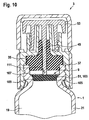
- FIG. 10 shows a fifth embodiment of the closure 3, the same and functionally identical elements are provided with the same reference numerals, so that reference is made to the preceding description.
- the retaining element 51 here comprises a closure disc 103.
- the closure disc 103 can be arranged such that it closes the distal chamber 19 so that no powder can enter the channel 45.
- the powder syringe 1 preferably comprises a constriction 105 in the mouth region 37.
- the wall 21 jumps radially inward in this region, so that the constriction 105 is formed.
- the closure plate 103 is formed so that it can bear sealingly against the constriction 105.
- it preferably has a - in the circumferential direction - extending, radial projection 107 on.
- the closure disk 103 preferably has an outer diameter which corresponds to the inner diameter of the constriction 105.
- the outer contour of the closure disc 103 follows, as it were, the inner contour of the constriction 105 or of the mouth region 37, so that it rests sealingly against the wall 21 with the projection 107 and the region 109.
- the closure cap 53 preferably comprises a rod-shaped projection, which is designed here as a locking pin 111 and the channel 45 passes through.
- a rod-shaped projection which is designed here as a locking pin 111 and the channel 45 passes through.
- the constriction 105 is preferably provided in the region of the distal end 9 of the powder syringe 1.
- the closure disc 103 preferably comprises rubber or TPE, more preferably it consists of at least one of these materials. It then has very good sealing properties, in addition, the materials mentioned are suitable for primary contact.
- FIG. 11 shows the embodiment according to FIG. 10 in activated state. Identical and functionally identical elements are provided with the same reference numerals, so that reference is made to the preceding description.
- This has at least one projection, in this case three projections 115, 115 ', 115 ", on a surface 113 facing the sealing element 35. With these, it is supported on a mating surface 117 of the sealing element 35.
- the protrusions 115 thus form the surface 113 and held the mating surface 117 at a distance from each other, so that between them and between the projections 115, 115 ', 115 ", a fluid path is formed.
- the solution emerging from the distal chamber 19 can therefore flow around the closure disk 103 and enter the channel 45. From there it can in turn be delivered to the cannula 91.
Landscapes
- Health & Medical Sciences (AREA)
- Hematology (AREA)
- Engineering & Computer Science (AREA)
- Anesthesiology (AREA)
- Biomedical Technology (AREA)
- Heart & Thoracic Surgery (AREA)
- Vascular Medicine (AREA)
- Life Sciences & Earth Sciences (AREA)
- Animal Behavior & Ethology (AREA)
- General Health & Medical Sciences (AREA)
- Public Health (AREA)
- Veterinary Medicine (AREA)
- Infusion, Injection, And Reservoir Apparatuses (AREA)
- Medical Preparation Storing Or Oral Administration Devices (AREA)
Claims (15)
- Fermeture pour une seringue à poudre (1) comprenant- un corps de base (33),- un élément d'étanchéité (35) placé de telle façon sur le corps de base (33) qu'il repose en étanchéité sur une ouverture distale (9) d'une seringue à poudre (1), lorsque la fermeture (3) est placée dans sa position de fermeture sur la seringue à poudre (1), et- un canal (45) qui traverse le corps de base (33) et l'élément d'étanchéité (35) et présente des extrémités proximale et distale (47, 49), et comprenant- un élément de retenue (51) qui est conçu et/ou peut être agencé de manière à empêcher en grande partie une pénétration de poudre (27) d'une chambre (19) de la seringue à poudre dans le canal (45) avant une activation de la seringue à poudre (1), lorsque la fermeture (3) est placée dans sa position de fermeture sur la seringue à poudre (1),
caractérisée en ce que- la fermeture (3) présente un bouchon de fermeture (53) qui ferme l'extrémité distale (49) du canal (45),- le bouchon de fermeture (53) présente une avancée (55) qui traverse le canal (45) et sur laquelle est prévu l'élément de retenue (51), et que- l'élément de retenue (51) est conçu en tant que renflement (57) de l'avancée (55). - Fermeture selon la revendication 1, caractérisée en ce que l'élément de retenue (51) est conçu en tant que membrane (67) fendue de préférence.
- Fermeture selon la revendication 2, caractérisée en ce que la membrane (67) est conçue d'un seul tenant avec l'élément d'étanchéité (35) et est placée de préférence sur l'extrémité proximale (47) du canal (45).
- Fermeture selon l'une des revendications précédentes, caractérisée en ce que l'élément de retenue (51) comprend un élément mobile le long du canal (45), de préférence une bille (85), par lequel l'extrémité proximale (47) du canal (45) peut être fermée.
- Fermeture selon la revendication 4, caractérisée en ce qu'un moyen de fixation (87) pour l'élément mobile est prévu sur l'extrémité proximale (47) du canal (45).
- Fermeture selon la revendication 4 ou 5, caractérisée en ce qu'un élément de retenue (89) pour l'élément mobile est prévu au niveau de l'extrémité distale (49) du canal (45).
- Fermeture selon l'une des revendications précédentes, caractérisée en ce que l'élément de retenue (51) comprend une substance soluble (97), lyophilisée de préférence.
- Fermeture selon la revendication 7, caractérisée en ce qu'un élargissement (99) pour recevoir la substance soluble (97) est prévu au niveau de l'extrémité proximale (47) du canal (45).
- Fermeture selon l'une des revendications précédentes, caractérisée en ce que l'élément de retenue (51) comprend une rondelle de fermeture (103) qui est ainsi conçue qu'elle peut se poser en étanchéité sur un resserrement (105) d'une seringue à poudre (1) pour empêcher une pénétration de poudre (27) dans le canal (45).
- Fermeture selon la revendication 9, caractérisée en ce que la rondelle de fermeture (103) présente, vu dans le sens périphérique, un épaulement radial (107) étendu.
- Fermeture selon l'une des revendications 9 ou 10, caractérisée en ce que la rondelle de fermeture (103) présente au moins une avancée (115) sur une surface (113) tournée vers l'élément d'étanchéité (35).
- Fermeture selon l'une des revendications 9 à 11, caractérisée en ce que le bouchon de fermeture (53) présente une avancée en forme de bâtonnet qui traverse le canal et tient la rondelle de fermeture (103) en position étanche avec la seringue à poudre (1) dans la position de fermeture de la fermeture (3).
- Seringue à poudre comprenant une ouverture distale (9), caractérisée par une fermeture (3) selon l'une des revendications 1 à 12.
- Seringue à poudre selon la revendication 13, caractérisée en ce que la seringue à poudre (1) est conçue en tant que système à chambre double.
- Seringue à poudre selon l'une des revendications 13 ou 14, caractérisée en ce que la seringue à poudre (1) présente un rétrécissement (105) au niveau de l'extrémité distale (9).
Priority Applications (2)
| Application Number | Priority Date | Filing Date | Title |
|---|---|---|---|
| EP15150522.9A EP2893946B1 (fr) | 2011-03-03 | 2012-02-23 | Bouchon pour seringue de poudre et seringue de poudre |
| EP15150520.3A EP2893915A1 (fr) | 2011-03-03 | 2012-02-23 | Bouchon pour seringue de poudre et seringue de poudre |
Applications Claiming Priority (2)
| Application Number | Priority Date | Filing Date | Title |
|---|---|---|---|
| DE201110013792 DE102011013792A1 (de) | 2011-03-03 | 2011-03-03 | Verschluss für eine Pulverspritze und Pulverspritze |
| PCT/EP2012/000787 WO2012116792A1 (fr) | 2011-03-03 | 2012-02-23 | Bouchon pour seringue de poudre et seringue de poudre |
Related Child Applications (4)
| Application Number | Title | Priority Date | Filing Date |
|---|---|---|---|
| EP15150520.3A Division EP2893915A1 (fr) | 2011-03-03 | 2012-02-23 | Bouchon pour seringue de poudre et seringue de poudre |
| EP15150520.3A Division-Into EP2893915A1 (fr) | 2011-03-03 | 2012-02-23 | Bouchon pour seringue de poudre et seringue de poudre |
| EP15150522.9A Division EP2893946B1 (fr) | 2011-03-03 | 2012-02-23 | Bouchon pour seringue de poudre et seringue de poudre |
| EP15150522.9A Division-Into EP2893946B1 (fr) | 2011-03-03 | 2012-02-23 | Bouchon pour seringue de poudre et seringue de poudre |
Publications (2)
| Publication Number | Publication Date |
|---|---|
| EP2680907A1 EP2680907A1 (fr) | 2014-01-08 |
| EP2680907B1 true EP2680907B1 (fr) | 2016-02-17 |
Family
ID=45808729
Family Applications (3)
| Application Number | Title | Priority Date | Filing Date |
|---|---|---|---|
| EP15150520.3A Withdrawn EP2893915A1 (fr) | 2011-03-03 | 2012-02-23 | Bouchon pour seringue de poudre et seringue de poudre |
| EP12707475.5A Active EP2680907B1 (fr) | 2011-03-03 | 2012-02-23 | Bouchon pour seringue de poudre et seringue de poudre |
| EP15150522.9A Active EP2893946B1 (fr) | 2011-03-03 | 2012-02-23 | Bouchon pour seringue de poudre et seringue de poudre |
Family Applications Before (1)
| Application Number | Title | Priority Date | Filing Date |
|---|---|---|---|
| EP15150520.3A Withdrawn EP2893915A1 (fr) | 2011-03-03 | 2012-02-23 | Bouchon pour seringue de poudre et seringue de poudre |
Family Applications After (1)
| Application Number | Title | Priority Date | Filing Date |
|---|---|---|---|
| EP15150522.9A Active EP2893946B1 (fr) | 2011-03-03 | 2012-02-23 | Bouchon pour seringue de poudre et seringue de poudre |
Country Status (11)
| Country | Link |
|---|---|
| US (2) | US9943648B2 (fr) |
| EP (3) | EP2893915A1 (fr) |
| JP (1) | JP6182073B2 (fr) |
| BR (1) | BR112013022566B1 (fr) |
| CA (2) | CA3045962C (fr) |
| DE (1) | DE102011013792A1 (fr) |
| ES (2) | ES2566104T3 (fr) |
| MX (1) | MX337219B (fr) |
| PT (1) | PT2893946T (fr) |
| RU (1) | RU2579626C2 (fr) |
| WO (1) | WO2012116792A1 (fr) |
Families Citing this family (18)
| Publication number | Priority date | Publication date | Assignee | Title |
|---|---|---|---|---|
| DE102012022008A1 (de) * | 2012-11-09 | 2014-05-15 | Vetter Pharma-Fertigung GmbH & Co. KG | Spritzenverschluss |
| WO2014179143A1 (fr) * | 2013-04-29 | 2014-11-06 | 3M Innovative Properties Company | Seringue pour administrer un médicament |
| CA2920632A1 (fr) * | 2013-08-07 | 2015-02-12 | Unitract Syringe Pty Ltd | Adaptateurs de raccord luer pour seringues |
| EP3030292A4 (fr) * | 2013-08-07 | 2017-03-15 | Unitract Syringe Pty Ltd | Adaptateurs de raccord luer pour seringues à aiguille rétractable |
| ES2755758T3 (es) | 2017-03-31 | 2020-04-23 | Schott Kaisha Private Ltd | Conjunto de tapa de punta de jeringa, jeringa que comprende dicha tapa de punta de jeringa y método para obturar un cilindro de jeringa |
| EP3689396A4 (fr) * | 2017-10-31 | 2020-08-19 | Terumo Kabushiki Kaisha | Seringue et seringue pré-remplie |
| USD862694S1 (en) | 2017-11-08 | 2019-10-08 | Schott Kaisha Pvt. Ltd | Syringe cap for sealing syringe for medical purpose |
| CN107929881B (zh) * | 2017-12-25 | 2023-08-25 | 江南大学 | 一种制剂注射器一体化结构 |
| EP3810254B1 (fr) * | 2018-06-20 | 2024-02-21 | Fresenius Kabi Deutschland GmbH | Ensemble raccord destiné à raccorder des tuyaux médicaux comprenant un élément de recouvrement |
| DE102018210941A1 (de) * | 2018-07-03 | 2020-01-09 | Vetter Pharma-Fertigung GmbH & Co. KG | Stopfenvorrichtung, Medikamentenbehälter und Verfahren zur Durchmischung zweier Substanzen in einem Medikamentenbehälter |
| US11154663B2 (en) * | 2018-10-25 | 2021-10-26 | Sharps Technology Inc. | Pre-filled safety needle and syringe system |
| DE102019207970A1 (de) * | 2019-05-29 | 2020-12-03 | Vetter Pharma-Fertigung GmbH & Co. KG | Medizinischer Hohlkörper, medizinischer Hohlkörper mit einer Verschlusskappe, Verfahren zum Herstellen eines medizinischen Hohlkörpers, und Kit |
| US11911588B2 (en) | 2019-08-06 | 2024-02-27 | Microvention, Inc. | Syringe |
| BR112022025141A2 (pt) | 2020-06-09 | 2023-04-25 | Vectivbio Ag | Fabricação, formulação e dosagem de apraglutida |
| JP7499090B2 (ja) * | 2020-07-01 | 2024-06-13 | テルモ株式会社 | プレフィルドシリンジ、シリンジ組立体、プレフィルドシリンジの製造方法及び表面積増加方法 |
| DE102021127437A1 (de) | 2021-10-21 | 2023-04-27 | Vetter Pharma-Fertigung GmbH & Co. KG | Verschluss für einen medizinischen Hohlkörper, medizinischer Hohlkörper mit einem solchen Verschluss und Verfahren zur Herstellung eines solchen Verschlusses |
| WO2024062668A1 (fr) | 2022-09-20 | 2024-03-28 | テルモ株式会社 | Seringue pré-remplie, élément d'extrémité distale, cylindre externe de seringue et procédé de fabrication de seringue pré-remplie |
| CN119860644A (zh) * | 2024-07-26 | 2025-04-22 | 维昇药业 | 制药、化妆品或医美产品的冻干方法、冻干制剂和注射剂 |
Family Cites Families (28)
| Publication number | Priority date | Publication date | Assignee | Title |
|---|---|---|---|---|
| GB576720A (en) * | 1942-06-17 | 1946-04-17 | Squibb & Sons Inc | Sterilization |
| US3091240A (en) * | 1958-12-29 | 1963-05-28 | Robert K Mcconnaughey | Hypodermic syringe and ventable closure means |
| US3380449A (en) * | 1964-11-02 | 1968-04-30 | Stanley J. Sarnoff | Cartridge with burstable seal |
| US4059109A (en) * | 1976-07-27 | 1977-11-22 | Tischlinger Edward A | Mixing and dispensing disposable medicament injector |
| US4331146A (en) * | 1976-12-23 | 1982-05-25 | The West Company | Syringe assembly |
| EP0072057B1 (fr) | 1981-08-10 | 1988-02-10 | Duphar International Research B.V | Seringue à injection automatique |
| US4479801A (en) * | 1982-06-25 | 1984-10-30 | Cohen Milton J | Fluid dispensing device |
| DE3916101A1 (de) * | 1989-05-17 | 1990-11-22 | Vetter & Co Apotheker | Spritze fuer medizinische zwecke |
| DE4127650C1 (fr) * | 1991-08-21 | 1993-02-25 | Arzneimittel Gmbh Apotheker Vetter & Co Ravensburg, 7980 Ravensburg, De | |
| DE69413423T2 (de) | 1994-06-16 | 1999-06-02 | Kwik Kork International Inc., Christ Church | Korkstopfen für weinflaschen |
| NL9401173A (nl) | 1994-07-15 | 1996-02-01 | A P I S Medical Bv | Voorgevuld injektiespuitsamenstel. |
| AUPM922394A0 (en) * | 1994-11-03 | 1994-11-24 | Astra Pharmaceuticals Pty Ltd | Plastic syringe with overcap |
| US6196998B1 (en) * | 1994-12-12 | 2001-03-06 | Becton Dickinson And Company | Syringe and tip cap assembly |
| US5779668A (en) * | 1995-03-29 | 1998-07-14 | Abbott Laboratories | Syringe barrel for lyophilization, reconstitution and administration |
| JPH0910281A (ja) | 1995-06-28 | 1997-01-14 | Maeda Sangyo Kk | 薬剤容器の口部構造 |
| US6383168B1 (en) | 1998-12-08 | 2002-05-07 | Bioject Medical Technologies Inc. | Needleless syringe with prefilled cartridge |
| JP3591636B2 (ja) | 2000-04-03 | 2004-11-24 | ニプロ株式会社 | プレフィルドシリンジ |
| US6953445B2 (en) | 2000-10-10 | 2005-10-11 | Meridian Medical Technologies, Inc. | Wet/dry automatic injector assembly |
| US6666852B2 (en) * | 2000-12-04 | 2003-12-23 | Bracco Diagnostics, Inc. | Axially activated vial access adapter |
| WO2003070296A2 (fr) | 2002-02-15 | 2003-08-28 | Antares Pharma, Inc. | Injecteur avec canal de derivation |
| US6883222B2 (en) | 2002-10-16 | 2005-04-26 | Bioject Inc. | Drug cartridge assembly and method of manufacture |
| US20080009822A1 (en) * | 2003-12-18 | 2008-01-10 | Halkey-Roberts Corporation | Needleless access vial |
| AT500930B1 (de) | 2004-10-25 | 2007-03-15 | Pharma Consult Ges M B H & Co | Verfahren und vorrichtung zum lyophilisieren, rekonstituieren und verabreichen eines rekonstituierten wirkstoffes |
| US20080033347A1 (en) * | 2006-08-03 | 2008-02-07 | Becton, Dickinson And Company | Detachable needle syringe having reduced dead space |
| US8002751B2 (en) * | 2006-10-23 | 2011-08-23 | Sue Carr | Filter needle |
| WO2009043000A1 (fr) | 2007-09-27 | 2009-04-02 | Becton, Dickinson And Company | Cartouche pour poudre et médicament liquide |
| CA2735289A1 (fr) | 2008-08-30 | 2010-03-04 | Sanofi-Aventis Deutschland Gmbh | Cartouche et systeme d'aiguille associe |
| JP2010131064A (ja) * | 2008-12-02 | 2010-06-17 | Arte Corp | 容器兼用注射器 |
-
2011
- 2011-03-03 DE DE201110013792 patent/DE102011013792A1/de not_active Ceased
-
2012
- 2012-02-23 BR BR112013022566-1A patent/BR112013022566B1/pt active IP Right Grant
- 2012-02-23 ES ES12707475.5T patent/ES2566104T3/es active Active
- 2012-02-23 PT PT151505229T patent/PT2893946T/pt unknown
- 2012-02-23 US US14/002,580 patent/US9943648B2/en active Active
- 2012-02-23 EP EP15150520.3A patent/EP2893915A1/fr not_active Withdrawn
- 2012-02-23 RU RU2013144328/14A patent/RU2579626C2/ru active
- 2012-02-23 CA CA3045962A patent/CA3045962C/fr active Active
- 2012-02-23 WO PCT/EP2012/000787 patent/WO2012116792A1/fr not_active Ceased
- 2012-02-23 EP EP12707475.5A patent/EP2680907B1/fr active Active
- 2012-02-23 MX MX2013010102A patent/MX337219B/es active IP Right Grant
- 2012-02-23 CA CA2828906A patent/CA2828906C/fr active Active
- 2012-02-23 JP JP2013555782A patent/JP6182073B2/ja active Active
- 2012-02-23 EP EP15150522.9A patent/EP2893946B1/fr active Active
- 2012-02-23 ES ES15150522.9T patent/ES2626565T3/es active Active
-
2018
- 2018-01-09 US US15/865,350 patent/US10357611B2/en active Active
Also Published As
| Publication number | Publication date |
|---|---|
| EP2680907A1 (fr) | 2014-01-08 |
| MX2013010102A (es) | 2014-01-08 |
| PT2893946T (pt) | 2017-07-18 |
| EP2893946B1 (fr) | 2017-04-05 |
| DE102011013792A1 (de) | 2012-09-06 |
| CA3045962C (fr) | 2021-12-28 |
| BR112013022566B1 (pt) | 2021-05-11 |
| EP2893946A1 (fr) | 2015-07-15 |
| EP2893915A1 (fr) | 2015-07-15 |
| RU2013144328A (ru) | 2015-04-10 |
| ES2566104T3 (es) | 2016-04-11 |
| ES2626565T3 (es) | 2017-07-25 |
| BR112013022566A2 (pt) | 2016-12-06 |
| JP2014508603A (ja) | 2014-04-10 |
| US10357611B2 (en) | 2019-07-23 |
| JP6182073B2 (ja) | 2017-08-16 |
| RU2579626C2 (ru) | 2016-04-10 |
| WO2012116792A1 (fr) | 2012-09-07 |
| US9943648B2 (en) | 2018-04-17 |
| US20130338575A1 (en) | 2013-12-19 |
| US20180126081A1 (en) | 2018-05-10 |
| MX337219B (es) | 2016-02-18 |
| CA2828906A1 (fr) | 2012-09-07 |
| CA2828906C (fr) | 2021-10-19 |
| CA3045962A1 (fr) | 2012-09-07 |
Similar Documents
| Publication | Publication Date | Title |
|---|---|---|
| EP2680907B1 (fr) | Bouchon pour seringue de poudre et seringue de poudre | |
| EP2678054B1 (fr) | Tete de seringue d'injection, dispositif d'injection et seringue d'injection | |
| DE69302852T2 (de) | Automatische Spritze | |
| EP2252350B2 (fr) | Système d'administration de produit à élément d'actionnement pouvant être bloqué | |
| EP1186312B1 (fr) | Dispositif distributeur de substances | |
| EP2531164B1 (fr) | Dispositif pour prélever un fluide dans un flacon | |
| DE69513696T2 (de) | Ein trockenes Medikament enthaltende und dessen Rekonstitution und Injektion ermöglichende Spritze | |
| EP1804862B1 (fr) | Procedes et dispositifs de lyophilisation, de reconstitution et d'administration d'un principe actif reconstituant | |
| DE69216306T2 (de) | Vorgefüllte Zweikammer-Spritze | |
| DE69317650T2 (de) | Vorrichtung zur vorbereitung einer lösung, einer suspension oder einer emulsion einer medizinischen lösung | |
| DE69426644T2 (de) | Injektionskartusche | |
| AT505616B1 (de) | Injektionsspritze | |
| EP2588221B1 (fr) | Dispositif combiné de mélange et de déversement | |
| EP1406686A1 (fr) | Dispositif pour delivrer des substances | |
| WO2007020239A1 (fr) | Contenant a deux chambres et procede pour le remplir | |
| EP2680909A1 (fr) | Bouchon et procédé de fabrication dudit bouchon | |
| DE10140704A1 (de) | Verfahren zur Durchmischung einer schwer löslichen pharmazeutischen Substanz mit einem Lösungsmittel und Spritze zur Anwendung des Verfahrens | |
| EP1917055A2 (fr) | Contenant à deux chambres sans dérivation | |
| EP3801688B1 (fr) | Dispositif et procédé d'administration d'au moins une substance | |
| DE8235862U1 (de) | Zuspritzvorrichtung fuer ein infusions- oder transfusionssystem | |
| DE1296312B (de) | Zweikammerbehaelter zum getrennten Abfuellen und Aufbewahren von Medikamenten und Loesungen bzw. Verduennungsmitteln in einer zur spaeteren Vermischung und darauffolgenden Entnahme geeigneten Form | |
| WO2010085903A1 (fr) | Dispositif d'administration comprenant un élément de maintien pour le réservoir à fluide | |
| EP2953669B1 (fr) | Dispositif de distribution permettant de distribuer un fluide | |
| WO2016055445A1 (fr) | Système et procédé pour la préparation d'une injection | |
| EP3817706B1 (fr) | Dispositif bouchon, récipient de médicament et procédé pour le mélange de deux substances dans un récipient de médicament |
Legal Events
| Date | Code | Title | Description |
|---|---|---|---|
| PUAI | Public reference made under article 153(3) epc to a published international application that has entered the european phase |
Free format text: ORIGINAL CODE: 0009012 |
|
| 17P | Request for examination filed |
Effective date: 20131004 |
|
| AK | Designated contracting states |
Kind code of ref document: A1 Designated state(s): AL AT BE BG CH CY CZ DE DK EE ES FI FR GB GR HR HU IE IS IT LI LT LU LV MC MK MT NL NO PL PT RO RS SE SI SK SM TR |
|
| DAX | Request for extension of the european patent (deleted) | ||
| RIC1 | Information provided on ipc code assigned before grant |
Ipc: A61M 5/28 20060101AFI20150629BHEP Ipc: A61M 5/34 20060101ALI20150629BHEP Ipc: A61M 5/31 20060101ALN20150629BHEP |
|
| GRAP | Despatch of communication of intention to grant a patent |
Free format text: ORIGINAL CODE: EPIDOSNIGR1 |
|
| RIC1 | Information provided on ipc code assigned before grant |
Ipc: A61J 1/14 20060101ALN20150727BHEP Ipc: A61M 5/28 20060101AFI20150727BHEP Ipc: A61M 5/31 20060101ALN20150727BHEP Ipc: A61M 5/34 20060101ALI20150727BHEP |
|
| INTG | Intention to grant announced |
Effective date: 20150902 |
|
| GRAS | Grant fee paid |
Free format text: ORIGINAL CODE: EPIDOSNIGR3 |
|
| GRAA | (expected) grant |
Free format text: ORIGINAL CODE: 0009210 |
|
| RAP1 | Party data changed (applicant data changed or rights of an application transferred) |
Owner name: VETTER PHARMA-FERTIGUNG GMBH & CO. KG |
|
| AK | Designated contracting states |
Kind code of ref document: B1 Designated state(s): AL AT BE BG CH CY CZ DE DK EE ES FI FR GB GR HR HU IE IS IT LI LT LU LV MC MK MT NL NO PL PT RO RS SE SI SK SM TR |
|
| REG | Reference to a national code |
Ref country code: GB Ref legal event code: FG4D Free format text: NOT ENGLISH |
|
| REG | Reference to a national code |
Ref country code: FR Ref legal event code: PLFP Year of fee payment: 5 |
|
| REG | Reference to a national code |
Ref country code: CH Ref legal event code: EP |
|
| REG | Reference to a national code |
Ref country code: IE Ref legal event code: FG4D Free format text: LANGUAGE OF EP DOCUMENT: GERMAN |
|
| REG | Reference to a national code |
Ref country code: AT Ref legal event code: REF Ref document number: 775346 Country of ref document: AT Kind code of ref document: T Effective date: 20160315 Ref country code: CH Ref legal event code: NV Representative=s name: OFFICE ERNEST T. FREYLINGER S.A., CH |
|
| REG | Reference to a national code |
Ref country code: DE Ref legal event code: R096 Ref document number: 502012006013 Country of ref document: DE |
|
| REG | Reference to a national code |
Ref country code: ES Ref legal event code: FG2A Ref document number: 2566104 Country of ref document: ES Kind code of ref document: T3 Effective date: 20160411 |
|
| REG | Reference to a national code |
Ref country code: PT Ref legal event code: SC4A Free format text: AVAILABILITY OF NATIONAL TRANSLATION Effective date: 20160513 |
|
| REG | Reference to a national code |
Ref country code: SE Ref legal event code: TRGR |
|
| REG | Reference to a national code |
Ref country code: NL Ref legal event code: MP Effective date: 20160217 |
|
| REG | Reference to a national code |
Ref country code: LT Ref legal event code: MG4D |
|
| PG25 | Lapsed in a contracting state [announced via postgrant information from national office to epo] |
Ref country code: HR Free format text: LAPSE BECAUSE OF FAILURE TO SUBMIT A TRANSLATION OF THE DESCRIPTION OR TO PAY THE FEE WITHIN THE PRESCRIBED TIME-LIMIT Effective date: 20160217 Ref country code: NO Free format text: LAPSE BECAUSE OF FAILURE TO SUBMIT A TRANSLATION OF THE DESCRIPTION OR TO PAY THE FEE WITHIN THE PRESCRIBED TIME-LIMIT Effective date: 20160517 Ref country code: FI Free format text: LAPSE BECAUSE OF FAILURE TO SUBMIT A TRANSLATION OF THE DESCRIPTION OR TO PAY THE FEE WITHIN THE PRESCRIBED TIME-LIMIT Effective date: 20160217 |
|
| PG25 | Lapsed in a contracting state [announced via postgrant information from national office to epo] |
Ref country code: RS Free format text: LAPSE BECAUSE OF FAILURE TO SUBMIT A TRANSLATION OF THE DESCRIPTION OR TO PAY THE FEE WITHIN THE PRESCRIBED TIME-LIMIT Effective date: 20160217 Ref country code: NL Free format text: LAPSE BECAUSE OF FAILURE TO SUBMIT A TRANSLATION OF THE DESCRIPTION OR TO PAY THE FEE WITHIN THE PRESCRIBED TIME-LIMIT Effective date: 20160217 Ref country code: LV Free format text: LAPSE BECAUSE OF FAILURE TO SUBMIT A TRANSLATION OF THE DESCRIPTION OR TO PAY THE FEE WITHIN THE PRESCRIBED TIME-LIMIT Effective date: 20160217 Ref country code: PL Free format text: LAPSE BECAUSE OF FAILURE TO SUBMIT A TRANSLATION OF THE DESCRIPTION OR TO PAY THE FEE WITHIN THE PRESCRIBED TIME-LIMIT Effective date: 20160217 Ref country code: LT Free format text: LAPSE BECAUSE OF FAILURE TO SUBMIT A TRANSLATION OF THE DESCRIPTION OR TO PAY THE FEE WITHIN THE PRESCRIBED TIME-LIMIT Effective date: 20160217 |
|
| REG | Reference to a national code |
Ref country code: GR Ref legal event code: EP Ref document number: 20160400937 Country of ref document: GR Effective date: 20160628 |
|
| PG25 | Lapsed in a contracting state [announced via postgrant information from national office to epo] |
Ref country code: EE Free format text: LAPSE BECAUSE OF FAILURE TO SUBMIT A TRANSLATION OF THE DESCRIPTION OR TO PAY THE FEE WITHIN THE PRESCRIBED TIME-LIMIT Effective date: 20160217 Ref country code: DK Free format text: LAPSE BECAUSE OF FAILURE TO SUBMIT A TRANSLATION OF THE DESCRIPTION OR TO PAY THE FEE WITHIN THE PRESCRIBED TIME-LIMIT Effective date: 20160217 |
|
| REG | Reference to a national code |
Ref country code: DE Ref legal event code: R097 Ref document number: 502012006013 Country of ref document: DE |
|
| PG25 | Lapsed in a contracting state [announced via postgrant information from national office to epo] |
Ref country code: CZ Free format text: LAPSE BECAUSE OF FAILURE TO SUBMIT A TRANSLATION OF THE DESCRIPTION OR TO PAY THE FEE WITHIN THE PRESCRIBED TIME-LIMIT Effective date: 20160217 Ref country code: SM Free format text: LAPSE BECAUSE OF FAILURE TO SUBMIT A TRANSLATION OF THE DESCRIPTION OR TO PAY THE FEE WITHIN THE PRESCRIBED TIME-LIMIT Effective date: 20160217 Ref country code: SK Free format text: LAPSE BECAUSE OF FAILURE TO SUBMIT A TRANSLATION OF THE DESCRIPTION OR TO PAY THE FEE WITHIN THE PRESCRIBED TIME-LIMIT Effective date: 20160217 Ref country code: RO Free format text: LAPSE BECAUSE OF FAILURE TO SUBMIT A TRANSLATION OF THE DESCRIPTION OR TO PAY THE FEE WITHIN THE PRESCRIBED TIME-LIMIT Effective date: 20160217 |
|
| PLBE | No opposition filed within time limit |
Free format text: ORIGINAL CODE: 0009261 |
|
| STAA | Information on the status of an ep patent application or granted ep patent |
Free format text: STATUS: NO OPPOSITION FILED WITHIN TIME LIMIT |
|
| 26N | No opposition filed |
Effective date: 20161118 |
|
| REG | Reference to a national code |
Ref country code: FR Ref legal event code: PLFP Year of fee payment: 6 |
|
| PG25 | Lapsed in a contracting state [announced via postgrant information from national office to epo] |
Ref country code: SI Free format text: LAPSE BECAUSE OF FAILURE TO SUBMIT A TRANSLATION OF THE DESCRIPTION OR TO PAY THE FEE WITHIN THE PRESCRIBED TIME-LIMIT Effective date: 20160217 Ref country code: BG Free format text: LAPSE BECAUSE OF FAILURE TO SUBMIT A TRANSLATION OF THE DESCRIPTION OR TO PAY THE FEE WITHIN THE PRESCRIBED TIME-LIMIT Effective date: 20160517 |
|
| REG | Reference to a national code |
Ref country code: NL Ref legal event code: FP |
|
| PG25 | Lapsed in a contracting state [announced via postgrant information from national office to epo] |
Ref country code: MT Free format text: LAPSE BECAUSE OF FAILURE TO SUBMIT A TRANSLATION OF THE DESCRIPTION OR TO PAY THE FEE WITHIN THE PRESCRIBED TIME-LIMIT Effective date: 20160217 |
|
| REG | Reference to a national code |
Ref country code: FR Ref legal event code: PLFP Year of fee payment: 7 |
|
| PG25 | Lapsed in a contracting state [announced via postgrant information from national office to epo] |
Ref country code: HU Free format text: LAPSE BECAUSE OF FAILURE TO SUBMIT A TRANSLATION OF THE DESCRIPTION OR TO PAY THE FEE WITHIN THE PRESCRIBED TIME-LIMIT; INVALID AB INITIO Effective date: 20120223 Ref country code: CY Free format text: LAPSE BECAUSE OF FAILURE TO SUBMIT A TRANSLATION OF THE DESCRIPTION OR TO PAY THE FEE WITHIN THE PRESCRIBED TIME-LIMIT Effective date: 20160217 |
|
| PG25 | Lapsed in a contracting state [announced via postgrant information from national office to epo] |
Ref country code: IS Free format text: LAPSE BECAUSE OF FAILURE TO SUBMIT A TRANSLATION OF THE DESCRIPTION OR TO PAY THE FEE WITHIN THE PRESCRIBED TIME-LIMIT Effective date: 20160217 Ref country code: MK Free format text: LAPSE BECAUSE OF FAILURE TO SUBMIT A TRANSLATION OF THE DESCRIPTION OR TO PAY THE FEE WITHIN THE PRESCRIBED TIME-LIMIT Effective date: 20160217 Ref country code: MC Free format text: LAPSE BECAUSE OF FAILURE TO SUBMIT A TRANSLATION OF THE DESCRIPTION OR TO PAY THE FEE WITHIN THE PRESCRIBED TIME-LIMIT Effective date: 20160217 Ref country code: TR Free format text: LAPSE BECAUSE OF FAILURE TO SUBMIT A TRANSLATION OF THE DESCRIPTION OR TO PAY THE FEE WITHIN THE PRESCRIBED TIME-LIMIT Effective date: 20160217 Ref country code: LU Free format text: LAPSE BECAUSE OF NON-PAYMENT OF DUE FEES Effective date: 20160223 |
|
| PG25 | Lapsed in a contracting state [announced via postgrant information from national office to epo] |
Ref country code: AL Free format text: LAPSE BECAUSE OF FAILURE TO SUBMIT A TRANSLATION OF THE DESCRIPTION OR TO PAY THE FEE WITHIN THE PRESCRIBED TIME-LIMIT Effective date: 20160217 |
|
| PG25 | Lapsed in a contracting state [announced via postgrant information from national office to epo] |
Ref country code: NL Free format text: LAPSE BECAUSE OF FAILURE TO SUBMIT A TRANSLATION OF THE DESCRIPTION OR TO PAY THE FEE WITHIN THE PRESCRIBED TIME-LIMIT Effective date: 20160217 |
|
| PGRI | Patent reinstated in contracting state [announced from national office to epo] |
Ref country code: NL Effective date: 20170426 |
|
| P01 | Opt-out of the competence of the unified patent court (upc) registered |
Effective date: 20230504 |
|
| REG | Reference to a national code |
Ref country code: CH Ref legal event code: U11 Free format text: ST27 STATUS EVENT CODE: U-0-0-U10-U11 (AS PROVIDED BY THE NATIONAL OFFICE) Effective date: 20260301 |
|
| PGFP | Annual fee paid to national office [announced via postgrant information from national office to epo] |
Ref country code: NL Payment date: 20260220 Year of fee payment: 15 |
|
| PGFP | Annual fee paid to national office [announced via postgrant information from national office to epo] |
Ref country code: SE Payment date: 20260223 Year of fee payment: 15 |
|
| PGFP | Annual fee paid to national office [announced via postgrant information from national office to epo] |
Ref country code: GB Payment date: 20260223 Year of fee payment: 15 |
|
| PGFP | Annual fee paid to national office [announced via postgrant information from national office to epo] |
Ref country code: ES Payment date: 20260317 Year of fee payment: 15 |
|
| PGFP | Annual fee paid to national office [announced via postgrant information from national office to epo] |
Ref country code: IE Payment date: 20260219 Year of fee payment: 15 Ref country code: DE Payment date: 20260220 Year of fee payment: 15 |
|
| PGFP | Annual fee paid to national office [announced via postgrant information from national office to epo] |
Ref country code: AT Payment date: 20260218 Year of fee payment: 15 |
|
| PGFP | Annual fee paid to national office [announced via postgrant information from national office to epo] |
Ref country code: BE Payment date: 20260220 Year of fee payment: 15 Ref country code: IT Payment date: 20260220 Year of fee payment: 15 |
|
| PGFP | Annual fee paid to national office [announced via postgrant information from national office to epo] |
Ref country code: FR Payment date: 20260224 Year of fee payment: 15 |
|
| PGFP | Annual fee paid to national office [announced via postgrant information from national office to epo] |
Ref country code: PT Payment date: 20260209 Year of fee payment: 15 Ref country code: CH Payment date: 20260301 Year of fee payment: 15 |
|
| PGFP | Annual fee paid to national office [announced via postgrant information from national office to epo] |
Ref country code: GR Payment date: 20260220 Year of fee payment: 15 |