EP1804862B1 - Procedes et dispositifs de lyophilisation, de reconstitution et d'administration d'un principe actif reconstituant - Google Patents
Procedes et dispositifs de lyophilisation, de reconstitution et d'administration d'un principe actif reconstituant Download PDFInfo
- Publication number
- EP1804862B1 EP1804862B1 EP05799629A EP05799629A EP1804862B1 EP 1804862 B1 EP1804862 B1 EP 1804862B1 EP 05799629 A EP05799629 A EP 05799629A EP 05799629 A EP05799629 A EP 05799629A EP 1804862 B1 EP1804862 B1 EP 1804862B1
- Authority
- EP
- European Patent Office
- Prior art keywords
- chamber
- housing
- cartridge
- plunger
- cannula
- Prior art date
- Legal status (The legal status is an assumption and is not a legal conclusion. Google has not performed a legal analysis and makes no representation as to the accuracy of the status listed.)
- Expired - Lifetime
Links
Images





Classifications
-
- A—HUMAN NECESSITIES
- A61—MEDICAL OR VETERINARY SCIENCE; HYGIENE
- A61M—DEVICES FOR INTRODUCING MEDIA INTO, OR ONTO, THE BODY; DEVICES FOR TRANSDUCING BODY MEDIA OR FOR TAKING MEDIA FROM THE BODY; DEVICES FOR PRODUCING OR ENDING SLEEP OR STUPOR
- A61M5/00—Devices for bringing media into the body in a subcutaneous, intra-vascular or intramuscular way; Accessories therefor, e.g. filling or cleaning devices, arm-rests
- A61M5/178—Syringes
- A61M5/28—Syringe ampoules or carpules, i.e. ampoules or carpules provided with a needle
- A61M5/284—Syringe ampoules or carpules, i.e. ampoules or carpules provided with a needle comprising means for injection of two or more media, e.g. by mixing
-
- A—HUMAN NECESSITIES
- A61—MEDICAL OR VETERINARY SCIENCE; HYGIENE
- A61J—CONTAINERS SPECIALLY ADAPTED FOR MEDICAL OR PHARMACEUTICAL PURPOSES; DEVICES OR METHODS SPECIALLY ADAPTED FOR BRINGING PHARMACEUTICAL PRODUCTS INTO PARTICULAR PHYSICAL OR ADMINISTERING FORMS; DEVICES FOR ADMINISTERING FOOD OR MEDICINES ORALLY; BABY COMFORTERS; DEVICES FOR RECEIVING SPITTLE
- A61J1/00—Containers specially adapted for medical or pharmaceutical purposes
- A61J1/14—Details; Accessories therefor
- A61J1/20—Arrangements for transferring or mixing fluids, e.g. from vial to syringe
- A61J1/2089—Containers or vials which are to be joined to each other in order to mix their contents
-
- A—HUMAN NECESSITIES
- A61—MEDICAL OR VETERINARY SCIENCE; HYGIENE
- A61M—DEVICES FOR INTRODUCING MEDIA INTO, OR ONTO, THE BODY; DEVICES FOR TRANSDUCING BODY MEDIA OR FOR TAKING MEDIA FROM THE BODY; DEVICES FOR PRODUCING OR ENDING SLEEP OR STUPOR
- A61M5/00—Devices for bringing media into the body in a subcutaneous, intra-vascular or intramuscular way; Accessories therefor, e.g. filling or cleaning devices, arm-rests
- A61M5/178—Syringes
- A61M5/24—Ampoule syringes, i.e. syringes with needle for use in combination with replaceable ampoules or carpules, e.g. automatic
- A61M5/2448—Ampoule syringes, i.e. syringes with needle for use in combination with replaceable ampoules or carpules, e.g. automatic comprising means for injection of two or more media, e.g. by mixing
- A61M2005/2451—Ampoule syringes, i.e. syringes with needle for use in combination with replaceable ampoules or carpules, e.g. automatic comprising means for injection of two or more media, e.g. by mixing preventing delivery before mixing is completed, e.g. by locking mechanisms
-
- A—HUMAN NECESSITIES
- A61—MEDICAL OR VETERINARY SCIENCE; HYGIENE
- A61M—DEVICES FOR INTRODUCING MEDIA INTO, OR ONTO, THE BODY; DEVICES FOR TRANSDUCING BODY MEDIA OR FOR TAKING MEDIA FROM THE BODY; DEVICES FOR PRODUCING OR ENDING SLEEP OR STUPOR
- A61M5/00—Devices for bringing media into the body in a subcutaneous, intra-vascular or intramuscular way; Accessories therefor, e.g. filling or cleaning devices, arm-rests
- A61M5/178—Syringes
- A61M5/31—Details
- A61M2005/3103—Leak prevention means for distal end of syringes, i.e. syringe end for mounting a needle
- A61M2005/3104—Caps for syringes without needle
-
- A—HUMAN NECESSITIES
- A61—MEDICAL OR VETERINARY SCIENCE; HYGIENE
- A61M—DEVICES FOR INTRODUCING MEDIA INTO, OR ONTO, THE BODY; DEVICES FOR TRANSDUCING BODY MEDIA OR FOR TAKING MEDIA FROM THE BODY; DEVICES FOR PRODUCING OR ENDING SLEEP OR STUPOR
- A61M5/00—Devices for bringing media into the body in a subcutaneous, intra-vascular or intramuscular way; Accessories therefor, e.g. filling or cleaning devices, arm-rests
- A61M5/178—Syringes
- A61M5/31—Details
- A61M2005/3103—Leak prevention means for distal end of syringes, i.e. syringe end for mounting a needle
- A61M2005/3106—Plugs for syringes without needle
-
- A—HUMAN NECESSITIES
- A61—MEDICAL OR VETERINARY SCIENCE; HYGIENE
- A61M—DEVICES FOR INTRODUCING MEDIA INTO, OR ONTO, THE BODY; DEVICES FOR TRANSDUCING BODY MEDIA OR FOR TAKING MEDIA FROM THE BODY; DEVICES FOR PRODUCING OR ENDING SLEEP OR STUPOR
- A61M5/00—Devices for bringing media into the body in a subcutaneous, intra-vascular or intramuscular way; Accessories therefor, e.g. filling or cleaning devices, arm-rests
- A61M5/178—Syringes
- A61M5/31—Details
- A61M2005/3117—Means preventing contamination of the medicament compartment of a syringe
- A61M2005/3121—Means preventing contamination of the medicament compartment of a syringe via the proximal end of a syringe, i.e. syringe end opposite to needle cannula mounting end
-
- A—HUMAN NECESSITIES
- A61—MEDICAL OR VETERINARY SCIENCE; HYGIENE
- A61M—DEVICES FOR INTRODUCING MEDIA INTO, OR ONTO, THE BODY; DEVICES FOR TRANSDUCING BODY MEDIA OR FOR TAKING MEDIA FROM THE BODY; DEVICES FOR PRODUCING OR ENDING SLEEP OR STUPOR
- A61M5/00—Devices for bringing media into the body in a subcutaneous, intra-vascular or intramuscular way; Accessories therefor, e.g. filling or cleaning devices, arm-rests
- A61M5/178—Syringes
- A61M5/31—Details
- A61M2005/3123—Details having air entrapping or venting means, e.g. purging channels in pistons
-
- A—HUMAN NECESSITIES
- A61—MEDICAL OR VETERINARY SCIENCE; HYGIENE
- A61M—DEVICES FOR INTRODUCING MEDIA INTO, OR ONTO, THE BODY; DEVICES FOR TRANSDUCING BODY MEDIA OR FOR TAKING MEDIA FROM THE BODY; DEVICES FOR PRODUCING OR ENDING SLEEP OR STUPOR
- A61M5/00—Devices for bringing media into the body in a subcutaneous, intra-vascular or intramuscular way; Accessories therefor, e.g. filling or cleaning devices, arm-rests
- A61M5/178—Syringes
- A61M5/31—Details
- A61M5/3129—Syringe barrels
- A61M2005/3142—Modular constructions, e.g. supplied in separate pieces to be assembled by end-user
-
- A—HUMAN NECESSITIES
- A61—MEDICAL OR VETERINARY SCIENCE; HYGIENE
- A61M—DEVICES FOR INTRODUCING MEDIA INTO, OR ONTO, THE BODY; DEVICES FOR TRANSDUCING BODY MEDIA OR FOR TAKING MEDIA FROM THE BODY; DEVICES FOR PRODUCING OR ENDING SLEEP OR STUPOR
- A61M5/00—Devices for bringing media into the body in a subcutaneous, intra-vascular or intramuscular way; Accessories therefor, e.g. filling or cleaning devices, arm-rests
- A61M5/178—Syringes
- A61M5/31—Details
- A61M5/315—Pistons; Piston-rods; Guiding, blocking or restricting the movement of the rod or piston; Appliances on the rod for facilitating dosing ; Dosing mechanisms
- A61M5/31596—Pistons; Piston-rods; Guiding, blocking or restricting the movement of the rod or piston; Appliances on the rod for facilitating dosing ; Dosing mechanisms comprising means for injection of two or more media, e.g. by mixing
- A61M2005/31598—Pistons; Piston-rods; Guiding, blocking or restricting the movement of the rod or piston; Appliances on the rod for facilitating dosing ; Dosing mechanisms comprising means for injection of two or more media, e.g. by mixing having multiple telescopically sliding coaxial pistons encompassing volumes for components to be mixed
-
- A—HUMAN NECESSITIES
- A61—MEDICAL OR VETERINARY SCIENCE; HYGIENE
- A61M—DEVICES FOR INTRODUCING MEDIA INTO, OR ONTO, THE BODY; DEVICES FOR TRANSDUCING BODY MEDIA OR FOR TAKING MEDIA FROM THE BODY; DEVICES FOR PRODUCING OR ENDING SLEEP OR STUPOR
- A61M5/00—Devices for bringing media into the body in a subcutaneous, intra-vascular or intramuscular way; Accessories therefor, e.g. filling or cleaning devices, arm-rests
- A61M5/178—Syringes
- A61M5/24—Ampoule syringes, i.e. syringes with needle for use in combination with replaceable ampoules or carpules, e.g. automatic
- A61M5/2448—Ampoule syringes, i.e. syringes with needle for use in combination with replaceable ampoules or carpules, e.g. automatic comprising means for injection of two or more media, e.g. by mixing
-
- A—HUMAN NECESSITIES
- A61—MEDICAL OR VETERINARY SCIENCE; HYGIENE
- A61M—DEVICES FOR INTRODUCING MEDIA INTO, OR ONTO, THE BODY; DEVICES FOR TRANSDUCING BODY MEDIA OR FOR TAKING MEDIA FROM THE BODY; DEVICES FOR PRODUCING OR ENDING SLEEP OR STUPOR
- A61M5/00—Devices for bringing media into the body in a subcutaneous, intra-vascular or intramuscular way; Accessories therefor, e.g. filling or cleaning devices, arm-rests
- A61M5/178—Syringes
- A61M5/28—Syringe ampoules or carpules, i.e. ampoules or carpules provided with a needle
- A61M5/285—Syringe ampoules or carpules, i.e. ampoules or carpules provided with a needle with sealing means to be broken or opened
- A61M5/286—Syringe ampoules or carpules, i.e. ampoules or carpules provided with a needle with sealing means to be broken or opened upon internal pressure increase, e.g. pierced or burst
-
- A—HUMAN NECESSITIES
- A61—MEDICAL OR VETERINARY SCIENCE; HYGIENE
- A61M—DEVICES FOR INTRODUCING MEDIA INTO, OR ONTO, THE BODY; DEVICES FOR TRANSDUCING BODY MEDIA OR FOR TAKING MEDIA FROM THE BODY; DEVICES FOR PRODUCING OR ENDING SLEEP OR STUPOR
- A61M5/00—Devices for bringing media into the body in a subcutaneous, intra-vascular or intramuscular way; Accessories therefor, e.g. filling or cleaning devices, arm-rests
- A61M5/50—Devices for bringing media into the body in a subcutaneous, intra-vascular or intramuscular way; Accessories therefor, e.g. filling or cleaning devices, arm-rests having means for preventing re-use, or for indicating if defective, used, tampered with or unsterile
- A61M5/5013—Means for blocking the piston or the fluid passageway to prevent illegal refilling of a syringe
- A61M5/502—Means for blocking the piston or the fluid passageway to prevent illegal refilling of a syringe for blocking the piston
-
- A—HUMAN NECESSITIES
- A61—MEDICAL OR VETERINARY SCIENCE; HYGIENE
- A61M—DEVICES FOR INTRODUCING MEDIA INTO, OR ONTO, THE BODY; DEVICES FOR TRANSDUCING BODY MEDIA OR FOR TAKING MEDIA FROM THE BODY; DEVICES FOR PRODUCING OR ENDING SLEEP OR STUPOR
- A61M5/00—Devices for bringing media into the body in a subcutaneous, intra-vascular or intramuscular way; Accessories therefor, e.g. filling or cleaning devices, arm-rests
- A61M5/50—Devices for bringing media into the body in a subcutaneous, intra-vascular or intramuscular way; Accessories therefor, e.g. filling or cleaning devices, arm-rests having means for preventing re-use, or for indicating if defective, used, tampered with or unsterile
- A61M5/5086—Devices for bringing media into the body in a subcutaneous, intra-vascular or intramuscular way; Accessories therefor, e.g. filling or cleaning devices, arm-rests having means for preventing re-use, or for indicating if defective, used, tampered with or unsterile for indicating if defective, used, tampered with or unsterile
Definitions
- the invention relates to a device and to a method for lyophilization, reconstitution and administration of active ingredients.
- the device has an elongated housing with a discharge-side front housing end and a rear housing end opposite thereto.
- a first chamber with a lyophilisate contained therein is formed in the region of the front housing end.
- the first chamber is closed at its end facing the front end of the housing with a removable closure and sealed in the direction of the rear end of the housing with a piston.
- a second chamber is formed, wherein the second chamber is connected via an opening with the surrounding atmosphere.
- the membrane is designed so that it is permeable to gas, but not to bacteria.
- a carpule containing a solvent is arranged in the second chamber.
- separate connection means are provided between the first chamber and the carpule.
- a sealed, first drug container by containing a lyophilized drug.
- this drug container may be inserted into an applicator with a second container containing an injection fluid.
- a fluid connection between the first and second container can be made, so that under the action of a piston also inserted into the cylinder interior of the applicator, the liquid from the second Container can be pressed into the drug container.
- This receiving chamber is sealed at its discharge-side, front housing end with a detachable closure with a Luer-lock connection and at its end facing away from the front housing with a piston in conjunction with an adapter inserted in this.
- the adapter is made in two parts and consists of two nested, tubular parts, wherein the outer part is slidably mounted on the inner wall of the receiving chamber, wherein the inner tubular part is screwed via a thread in the outer tubular part and a passage opening in the piston in the the occluding the lyophilized drug receiving chamber closes.
- the inner part can be unscrewed and screwed instead of a filled with a solvent injection device.
- the present invention has for its object to provide a device for lyophiliseren, reconstituting and administering a reconstituted drug that allows safe storage of the lyophiliersten drug and sterile storage. Independently of this, it should be ensured that the lyophilisate and the reconstituted active substance do not leave the receiving chamber for the lyophilised active substance during the mixing process and administration.
- the device can be stored in different preparation stages each sealed for use and still form individual parts of an overall system, which can be assembled in a few steps to an injection device or to a dispenser for administering the reconstituted drug , It is advantageous that thereby the entire way, the drug takes in the interior of the device as well as the way of the solvent or the liquid to dissolve the drug is sterile and thereby the connection between the lyophilisate-containing chamber and the solvent containing carpule must be opened only when put into use and a primary leakage of closures is therefore avoided as possible.
- the device in each case has the lyophilized active substance stored in the first chamber, the number of devices to be held in storage can be reduced overall if the remaining device parts are also assembled and packaged in a sterilized state. Thus, only the device parts need to be stored with the drug with different active ingredients and it can be stored a smaller number of actuator with carpule, since they can be coupled with the same device parts having different agents immediately.
- the lyophilized active ingredient and sealed device already the carpule with the liquid to reconstitute the lyophilized drug is included.
- the Auden- and inner region of the carpule and the chamber for the drug is sterilized through the closure-side piston, the liquid for reconstitution of the active ingredient having carpule, continuously and can also when assembled with the drive units, for example, a piston rod or an additional piston rod housing or a Autoinjector unit the sterility will not be destroyed.
- the advantage is achieved that a corresponding volume of air remains in the chamber, via the compression of the feed rate or the insertion speed of the liquid for reconstitution of the active ingredient can be easily controlled.
- it is possible in a simple manner to ensure the venting of the interior of the first chamber during lyophilization of the active ingredient and, on the other hand, to seal the first chamber sufficiently tight and sterile without great effort immediately after the lyophilization of the active substance.
- a further embodiment according to claim 7 has proved to be advantageous in that it is made with a single connection cannula the connection between the lyophilisate-containing chamber and the solvent-containing carpule by this connecting cannula pierces the chamber closing piston and the sealing disc, which the carpule closes.
- a cannula accommodated in the piston can be provided, whereby a component carrying the cannula is saved. It is advantageous according to claim 9 directed against the carpule end of the cannula covered with a cap of a rubber-elastic material, so that the sterility is ensured in the interior of the chambers in this embodiment.
- the cannula end directed towards the carpule is arranged in a depression of the piston and this depression is closed by another membrane which is permeable to gas but not to bacteria, the part of the device containing the lyophilisate can already be be kept sterile prior to assembly with the carpule containing part.
- the first chamber can be formed by a glass cylinder, which in turn is accommodated in the housing.
- the active ingredient can be previously lyophilized.
- the embodiment according to claim 12 offers advantages in the assembly of the device.
- claims 13 and 14 facilitate sterile occlusion and prevent unintentional opening of the lyophilisate-containing chamber.
- Claims 15 and 16 relate to embodiments which are advantageous in lyophilizing the active ingredient in the first chamber.
- the embodiment according to claim 19, which relates to a two-part housing, offers considerable advantages in the manufacture and assembly of the device. If, according to claim 20, the two housing parts are connected by a thread with each other, they can be very easy to assemble. These threaded connection is advantageously provided according to claim 21 with a tamper-evident, so that it can be determined whether the connection was separated.
- claims 22 and 23 facilitate lyophilization of the drug in the first chamber while maintaining sterility.
- the embodiment described in claim 24 allows the sterile storage of the device without actuating means.
- the actuating means advantageously serves a coupling part according to claim 25.
- the actuating means are already mounted and received in a protective tube, which in turn ensures the sterility of the whole device.
- the preferred embodiment according to claim 29 allows a stepwise actuation of the device and the embodiment of claim 30 shows a possible embodiment of the locking means.
- a braking effect is achieved by the elastic deformability of the Kolhenstangen Suitee that prevents too rapid advancement of the piston rod and thus undesirable foaming during mixing of the active ingredient with the solvent.
- the defined in claim 33 embodiment of this device shows a particularly simple way to implement the restraint device.
- a device according to claim 39 is advantageous.
- the restraint device increases the safety of the sequence of operations occurring during actuation of the device.
- the object of the invention can also be solved independently of the design of the device by the method according to claim 42.
- the chosen procedures not only simplify the lyophilization of the active ingredient, but also provide a continuous process for preparing the lyophilized drug and its sterile packaging for economic reuse and ease of use for delivery of the lyophilized reconstituted drug.
- excellent quality of the lyophilized active ingredient and its sufficient storage time can be achieved while at the same time sterility until reconstitution of the active ingredient is ensured.
- An advantage of this solution also lies in the manifold possibilities for the individual method steps, which open up a multiplicity of device-technical possibilities and, above all, make possible a cost-effective modular system.
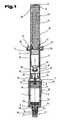
- FIG. 1 shows a first embodiment of a device according to the invention.
- a first chamber 1 containing a lyophilizate 26 is disposed in a housing 3 near its front, discharge-side housing end 6.
- the first chamber 1 is formed in a glass cylinder 23, which in turn is housed in the housing 3 made of plastic.
- the lyophilizate 26 was formed in the first chamber 1, as will be described later.
- the glass cylinder 23 containing the lyophilizate 26 has at its end located near the discharge-side, front housing end 6 a narrowed orifice 24 onto which an adapter 25 made of plastic is placed.
- the adapter 25 made of plastic can be molded or glued to the glass cylinder 23 or attached to the glass cylinder 23 with a snap device.
- the downstream end side of the glass cylinder projecting cylindrical projection which is occupied by the mouth 24 For attachment of the adapter 25 to a, the downstream end side of the glass cylinder projecting cylindrical projection which is occupied by the mouth 24, this extension between the end face of the glass cylinder 23 and the discharge end thereof has a circumferential groove 50. From the voltage applied to the front side part of the adapter 25 extend in the radial direction elastic snap arms, which have to the longitudinal center axis of the glass cylinder projecting snap hook, in this groove 50 and is thus the Adapter immovably connected to the glass cylinder 23.
- the adapter 25 further has a luer-lock attachment in its end region facing away from the glass cylinder 23.
- a Luer-lock approach which can be provided with appropriate locking means for fixing and holding the shutter 9 and a, to be connected to the adapter 25 injection needle.
- the contamination-free application of the injection solution i. the reconstituted active ingredient or the lyophilizate 26, a significant advantage of the inventive device of the method according to the invention.
- This freedom from contamination must be ensured over the entire period of use of the device.
- the sealing takes place on the discharge-side housing end 6 by means of the latchable and, if necessary, releasable cap 27 with the integrated sealing element 10 made of rubber rubber, which closes the opening of the gas cylinder 23 bacteria-tight.
- the adapter 25 has a luer-lock closure with adaptation, as this unintentional release of the closure 9 is avoided even when handling the device for their final use.
- a closure 9 which consists of a cap 27 made of plastic and a sealing element 10 held in this.
- the latter consists of pharmaceutical rubber and protrudes into the mouth 24 to close this tight.
- the cap 27 is provided in addition to or in place of the Luer-lock lock with a locking lug 46 which prevents inadvertent removal of the closure 9.
- the adapter 25 forms a luer lock or a luer lock coupling to which a luer connection, an injection needle or a hose leading to such or another component can be connected.
- the glass cylinder 23 has bypasses 45 running in the axial direction, which facilitate gas exchange during the lyophilization process serve, as will be explained below.
- a cylinder plug 11 which also consists of pharmaceutical rubber and has such axial extent, or can take in different positions, so that it either extends beyond the length of the bypasses 45 out or can be moved to a position, in which the cylinder plug 11 closes the glass cylinder 23 tightly.
- the rear side of the cylinder stopper 11 begins a second chamber 2, in which an existing glass or plastic cartridge 12 is added, which contains a solvent.
- the carpule 12 is closed at its discharge-side end by means of a cartridge rubber cartridge disc 37 which is held by a crimp cap 38 on the carpule 12.
- the discharge side facing away from the end of the carpule 12 is a Karpulenstopfen 31, which closes the solvent-containing interior of the carpule tight.
- a gas passage extending in the longitudinal direction of the housing 3 is provided.
- This gas passage may consist of a clearance between the outer diameter of the carpule and the inner diameter of the housing, or there may be provided fine longitudinal ribs or longitudinal grooves or elevations distributed over the surface or a corresponding roughness inside the housing or on the outside of the carpule.
- the passage of gas serves the sterilization of the device with ethylene oxide described in more detail below.
- At least one carpule support 39 is arranged on the inner wall of the housing 3, on which the carpule 12 is supported with its cartridge shoulder 36.
- a plurality of carpule supports 39 are arranged distributed on the circumference of the housing 3, which can be formed, for example, by softening and slight depression of the housing wall or with a separate component which can be inserted in the housing part.
- a transfer set 16 is arranged, which has the task, in use of the device, to direct the solvent contained in the cartridge 12 into the first chamber 1 for reconstitution of the lyophilisate.
- the transfer set 16 contains a continuous, held in a cannula guide 17 Connecting cannula 18.
- the connecting cannula 18 is open in this embodiment and therefore also continuous for gas, so that both sides of the transfer set 16 can be sterilized with ethylene oxide.
- the transfer set 16 is held in its axial position in the housing 3 by integrally formed on its circumference spring latching tabs 47 which engage in an arranged in the rear housing part 5 annular groove 48.
- the housing 3 of the device may expediently consist of a front, discharge-side housing part 4 and a rear housing part 5, which are screwed together releasably at a connection point 8.
- the connection point 8 may be covered with a label 35.
- This label 35 can be used for tamper evidence but also to ensure and maintain the sterility of the entire interior of the device, because the destruction or breakage of the label 35 indicates that the housing part 4 and 5 were separated from each other and thus the originality and thus possibly also the sterility is no longer present.
- the rear housing part 5 with a vertical planes arranged to the longitudinal axis bearing surface (flange 56 in FIG. 7 ) is provided for placing and sealing a sealing film
- a connecting device in particular a snap device is arranged, with the piston rod 29 and a first of several detents 40 for coupling and fixing the piston rod 29 to the rear housing part 5 can be used.
- This connecting device which may be formed by a jumping to the longitudinal axis circumferential point, can be engaged from radially to the longitudinal axis of elastically adjustable snap arms and allows a support of the piston rod 29 is positioned between the cartridge plug 31 and the inwardly projecting point of the connecting device is positioned and a feed movement can exercise the cartridge plug 31.
- the carpule 12 can act with a partially over the surface of the outside of the carpule 12 Press fit be connected to the rear housing part 5, or there are corresponding over the inner surface of the rear housing part 5 before protruding projections formed holding elements for the carpule.
- the retention force of the press fit or the restraints is less than a support of the cartridge sealing washer 37 on the crimping cap 38, since the advancement of the carpule 12 for engagement in a transfer seat 16 using the medium in the carpule 11, due to the incompressibility of the liquid via the Karpulenstopfen 31 of the carpule 12. That is, the anchoring of the cartridge sealing disk 37 must be so strong that the force required to overcome the interference fit or the retainer results in a necessary thrust force exerted on the carpule in the region of the cartridge sealing disk 37, before the carpule Washer 37 is pierced by the connecting cannula 18 of the transfer set 16.
- the piston rod 29 is equipped with a plurality of detents 40, whose function will be explained in more detail below.
- a flange-like finger rest 32 is formed at the rear end of the housing 7. The piston rod is received in an axially displaceable manner in a formed in the rear housing part 5 brake cylinder extension 41.
- a piston rod housing 30 completely covering the piston rod 29 is connected to a connecting flange 33 with the rear housing part 5, for example by a weld 42, which can be made by ultrasound or gluing or Anformung and only so strongly dimensioned that they quasi a breaking point and thus forms an additional quality criterion that makes it possible to remove the piston rod housing 30 from the housing 3.
- a label 34 covering the connecting flange 33 and the finger rest 32 serves as a guarantee seal, the breakage of which indicates that the piston rod housing 30 has been removed from the housing 3.
- the end face at its rear end, the piston rod housing 30 has an opening 13 which is closed by a resting on a support grid 28 membrane 14.
- the membrane 14 is such that it is permeable to gas, but not to bacteria. So-called medical grade paper meets this requirement.
- the membrane 14 serves to prevent unintentional puncture of Teretpapiers during sterilization or during subsequent transport until use.
- This membrane 14 can be integrally molded or molded into the piston rod housing 30 But it is also possible to press the grid, glued, latched or otherwise fix or replace by a flow of a fabric, knitted fabric or other membrane or a filter.
- the front housing part 4, the glass cylinder 23, the glass cylinder 23 at the rear tightly closing cylinder plug 11 and the glass cylinder 23 front tightly closing adapter 25 with the attached to this closure 9 form a unit that is produced in a closed process and sold as such and / or the further processing can be supplied.
- the manufacture and assembly of this unit are carried out in appropriate clean rooms in order to ensure as particle-free production as possible even before sterilization.
- the pharmaceutical rubber parts consist of a rubber formulation suitable for lyophilization.
- the pre-assembly of this unit is such that first the shutter 9 is assembled by the sealing element 10 is installed with a mounting device in the cap 27. Then, the shutter 9 is connected to the adapter 25, e.g. connected by Luer-lock system, wherein the cap 27 engages with the locking projection 46 in the adapter 25, so that a secure, but again releasable, securing against unintentional release of the two parts is given from each other.
- cylinder plugs 11 which have already been washed by default, siliconized and sterilized, are introduced into receiving magazines of a bottling plant and disposed of for further processing.
- the cylinder plugs 11 may also be washed, siliconized, sterilized and dried in a standard filling line.
- glass cylinder 23 are introduced into the bottling plant, washed, siliconized and sterilized in a hot air tunnel.
- the adapter 25 by means of a snap connection at the undercut of the glass cylinder neck 23 indissoluble.
- the mouth 24 of the glass cylinder 23 is sealed bacteria-tight with the sealing element 10 of the closure 9.
- the dispensing side sterile closed glass cylinder 23 are placed in recordings standing in the bottling plant and the drug solution can now be dosed into the open glass cylinder 23.
- the lyophilization process is initiated at this moment, wherein the venting or the gas exchange over the still open cross-sections of the glass cylinder 23 takes place.
- the cylinder plugs 11 are automatically pushed into the glass cylinders 23, sealing them tightly. In this embodiment can be dispensed with the bypasses 45 in the glass cylinder.
- the prepared, sterile cylinder plug 11 are fed and inserted into the glass cylinder 23 accurately positioned, and only so far that the bypasses 45 of the glass cylinder 23 remain open, so that a gas exchange during the subsequent lyophilization on the open transverse steps of the bypasses 45 can take place.
- the lyophilization process can be initiated, wherein the venting or the gas exchange via the open cross sections of the bypasses 45 takes place.
- the cylinder plugs 11 are automatically pushed to the end position in the glass cylinders 23, whereby the bypasses 45 are sealed.
- glass cylinders 23 without bypasses 45 are used.
- cylinder plug 11 are used, whose diameter is greater than the inner diameter of the glass cylinder 23 and having in the region of its circumference axially extending vent passages. At least in the area of these vent passages, the cylinder plug 11 has a larger diameter beyond it, so that when the latter is inserted more deeply into the chamber, the vent passages are tightly closed by the stronger compression.
- the cross-section of these vent passages is dimensioned such that it is closed by the elastic deformation of the cylinder plug 11 when it is completely received in the glass cylinder 23.
- cylinder plugs 11 are first supplied and inserted accurately positioned in the glass cylinder 23, and only so far, that the vent passages in the cylinder plug 11 remain open, so that gas exchange during the subsequent lyophilization can take place via the open transverse steps of the vent passages. Immediately after the completion of the lyophilization, the cylinder plugs 11 are automatically pushed to the end position in the glass cylinders 23, whereby the vent passages are squeezed and sealed so tightly.
- the glass cylinder 23 are first sealed at its mouth 24 facing away from the side with the cylinder plug 11 and then placed in receptacles with upward-oriented mouth 24 standing in the bottling plant. Thereafter, the drug solution is filled through the mouth 24 metered into the glass cylinder 23. In the subsequent lyophilization, the gas exchange takes place through the open mouth 24 of the glass cylinder 23. After completion of the lyophilization, the glass cylinders 23 are closed with the pre-assembled closures 9 on the discharge side. In this case, the adapter 25 by means of a snap connection at the undercut of the glass cylinder neck 23 indissoluble. As a result, the mouth 24 of the glass cylinder 23 is closed bacteria-tight with the sealing element 10 of the closure 9.
- the glass cylinder 23 were filled and lyophilized, these can now, as both sides bacteria-tightly closed, the further, optionally external Fertigmontagerati be supplied.
- the assembly steps of the device described below can be performed temporally and locally independently of the previously described assembly steps.
- the finished, on both sides bacteria-tight sealed glass cylinder 23 with the lyophilized active ingredient is introduced by means of a mounting device in the front housing part 4.
- a secure coupling and optionally a torsion protection between the housing part 4 and the adapter 25 and the glass cylinder 23 is achieved, so that the closure 9 can be removed from the device, without causing relative movement or possibly a rotation between the glass cylinder 23 relative to Adapter 25 or the housing part 4 can come.
- the now completed unit which is referred to below as injection unit, is thus completed for further assembly.
- Another unit of the device is formed as follows. In the at its rear end e.g. through the inner circumferential collar narrowed rear housing part 5, the carpule 12 with the solvent (water for injectable preparations) and finally the transfer set 16 is introduced from the joint 8 ago forth first.
- the piston rod 29 is first introduced through the constriction until it engages with its snap connection, then the piston rod housing 30 is placed with the integrally formed connecting flange 33 on the finger rest 32 of the housing part 5.
- the connection is still secured with a 4-point welding. Subsequently, the flange Fingerauflagen für is completely labeled to provide the originality can.
- activator unit can now be connected to the injection unit described above by the rear housing part 5 screwed onto the front housing part 4 and the junction 8 is then also labeled all around, in order to provide quality proof at this point can.
- the thus completely assembled device can now be supplied to a final sterilization process, in which a gas, preferably ethylene oxide, is supplied to the interior of the device without thereby entering the first chamber 1.
- a gas preferably ethylene oxide
- the gas penetrates through the membrane 14, with which the present in the rear end of the piston rod housing 30 opening 13 is covered bacteria-tight, first enters the interior of the piston rod housing, where it sterilizes this interior together with the piston rod 29 contained therein.
- FIG. 2 is shown a further embodiment of the device.
- the first chamber is not formed in a glass cylinder, but directly in the existing plastic front housing part 4.
- a coupling projection 51 which is preferably designed as a Luer-lock approach, directly on the front housing part 4 molded.
- the first chamber 1 as in the embodiment of Figure 1, bacteria-tightly closed with a cylinder plug 11 made of pharmaceutical rubber, which also two different embodiments of the cylinder plug 11 can be used, namely with or without vent passages.
- bypasses 45 are present in the front housing part 4 and the cylinder plug 11 accordingly has no vent passages.
- the embodiment of the device according to FIG. 3 is similar to the embodiment described above according to FIG. 2 , Again, the first chamber 1 is formed in the front housing part 4 made of plastic. However, in this embodiment, another embodiment of the transfer set 16 is incorporated, which is constructed so that the transfer set 16 takes over the rear boundary and seal of the first chamber 1, as well as the function of a piston for expelling the reconstituted drug from the first chamber 1. Consequently, in this embodiment, in connection with the embodiments according to the FIGS. 1 and 2 described cylinder plug 11 superfluous.
- the choice of the materials used for the above-described embodiments of the device is primarily with the aim of long-term assurance of functionality and mechanical stability, even under extreme conditions.
- the front housing part 4 the cylinder plug 11, the cartridge plug 31, the cartridge sealing disk 37, the connecting cannula 18, the injection cannula 49 and all sealing elements such as O-rings beyond the fulfillment of the requirements for materials for the production of Medical devices required.
- the resistance of the material used to ethylene oxide is important for all components.
- the front housing part is preferably made of cyclolefin copolymer, hereinafter called COC. It is an amorphous thermoplastic known under the trade name Topas 6013.
- the front housing part 4 takes over in the embodiments FIG. 2 and 3 the function of a primary packaging containing the lyophilisate.
- the choice of said material for the execution of this housing part was therefore in view of the high demands on precise shaping, chemical resistance, glassy transparency, high heat resistance and breaking strength, autoclaving at 121 ° C and sterilizability by gamma irradiation and ethylene oxide.
- COC meets all the requirements that are placed on pharmaceutical containers for the storage of parenteral substances according to EP / JP and USP incl. USP Class VI. Due to the high processing temperatures pyrogen free can be guaranteed. Furthermore, the excellent barrier against water vapor makes it possible to store medicines in containers for several years.
- the COC containers are particularly suitable for the packaging of biotech products, toxic products, solvents, lyophilisates and other pharmaceuticals because of the material properties given above, making plastic pharmaceutical containers a real alternative to glass pharmaceutical containers.
- the shape of the front housing part 4 can be optimally designed and manufactured in accordance with the requirements for size, ventilation channels (bypasses), syringe head and neck, etc., due to the shape-technical design possibilities which are possible through the use of thermoplastics.
- the glass cylinder 23 are preferably made of borosilicate glass, which is known for example under the trade name Fiolax.
- This type of glass meets the requirements of the pharmacopoeia USP, European Pharmacopoeia, Japanese Pharmacopoeia and the German Pharmacopoeia (DAB) with regard to chemical resistance and light protection. Compliance with the heavy metal limit values (lead, cadmium, mercury, chromium VI) according to the European directive 94/62 / CE is guaranteed. Glass is completely inert and dense to ethylene oxide.
- a polyacetate (POM) is used for the cannula guide 17.
- POM is also designed by the manufacturer to produce parts for food contact use and complies with FDA and European Union regulations.
- the cannula guide that, when the device is used as intended, it has no direct contact with the drug and the human body. Nevertheless, since the cannula guide receives the connection cannula 18, it has been important to use a material that is specified by the manufacturer for use in the field of medical devices.
- connection cannula 18 stainless steel (NIRO 1.403, AISI 304) was chosen.
- the stainless steel used is suitable and specified for the manufacture of medical cannulas and also suitable for sterilization with ethylene oxide.
- the fixation of the connecting cannula 18 in the cannula guide 17 takes place with the aid of a UV-curing cyano-acrylate adhesive, for example an adhesive known under the trade name Loctite 4304.
- the examination of the adhesive suitability for ensuring the cannula fixation also after the sterilization took place in the form of the needle stick seat test (strength between cannula guide 17 and connection cannula 18) according to EN ISO 7864 at the injection units.
- the selected sterilization process with ethylene oxide serves to ensure the sterility of the entire device, excluding the contained therein, in the first chamber 1 gas-tight packed drug (lyophilisate) and the gas-tight packed in the cartridge 12 solvent (WFI).
- the functioning as bacteria-tight barrier membranes 14 and 15 are made of medical grade paper with a basis weight of 60g / m 2.
- the paper is coated with the piston rod housing 30 with polyethylene for sealability.
- the material used is designed for use in the medical / pharmaceutical sector, especially for the supply of sterile goods and meets the requirements of EN 868 parts 1 and 7. It is well-permeable to ethylene oxide and specified as bacteria-proof.
- the ETO sterilization of the device must not lead to any change of the lyophilisate present in the bacteria-tightly sealed first chamber 1 and the solvent present in the carpule 12. To ensure this, it must be ensured that no ethylene oxide can penetrate into the interior of the first chamber 1 and the carpule 12. Practical verification of the ethylene oxide tightness of the syringe barrel with the lyophilizate and the carpule with the solvent (WFI) was made by examining the contents of the cartridge and the contents of the first chamber 1 of sterilized devices according to the invention, in the described embodiments on ethylene oxide. Ethylene oxide could not be detected in any of the cartridges and first chambers sterilized with ethylene oxide. Thus, a change in the solvent stored therein (water for injection) and the lyophilisate can be excluded by the action of ethylene oxide.
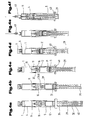
- FIGS. 4a to 4f the use of the described device in the embodiment according to FIG. 2 explained.
- the activator unit is secured to the piston rod housing 30 and the connection between the activator unit and the injection unit (rear housing part 5) is provided with the label 34.
- the other end of the connecting cannula 18 also pierces the carpule sealing disc 37 of the carpule 12 and the connecting cannula 18 penetrates into the interior of the carpule 12, so now a continuous connection between the carpule interior (with the solvent) and the first Chamber 1 (with the lyophilisate) is made.
- One of the detents 40 of the piston rod 29 now automatically engages in the rear housing part 5 and secures the transfer set 16 in conjunction with the cylinder plug 11 in this position. Retraction of the piston rod from this position is no longer possible. This ensures that the connection between the first chamber 1 with the lyophilisate and the carpule with the solvent remains upright via the connecting cannula 18.
- the injection solution is pressed out of the first chamber 1 by means of the cylinder stopper 11.
- the device After injection, the device finally reaches the in Fig. 4f shown position.
- a further detent 40 engages in the housing part 5 and secures the piston rod 29 in its end position against pulling out. For a reuse of the device is effectively prevented.
- the activator unit is secured to the piston rod housing 30 and the connection between the activator unit and the injection unit (rear housing part 5) with the tamper-evident closure (label 34).
- the closure 9 is removed and the injection cannula 49 is attached ( FIG. 5e ). After venting the first chamber 1 via the cannula, the injection can take place.
- the brake lugs 54 which have so far retained the transfer set 16 in a projection in the front housing part 4, are pushed away and the transfer set 16 begins to move towards the delivery side of the device.
- the transfer set 16 now serves as a syringe plunger and forces the injection solution out of the first chamber 1.
- the device After injection, the device finally reaches the in Fig. 5f shown position in which a further detent 40 engages in the housing part 5 and secures the piston rod 29 in its final position against withdrawal. For a reuse of the device is effectively prevented.
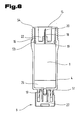
- FIG. 6 shows an embodiment of an injection unit, which can be manufactured separately, stored and sold and later assembled with an activator.
- the first, the lyophilizate 26 containing chamber 1 is formed directly through the front housing part 4 and has on the delivery side a coupling lug 51, which forms a Luer-lock approach and from the cap 27 with the sealing element 10 disposed therein closure 9 releasably holds.
- a transfer set 16th used is different from the one in FIG. 3 illustrated transfer set differs in that a recess 22 in which the Karpu structuriitige end 20 of the connecting cannula 18 is closed by a membrane 15 against the outside bacteria-tight.
- the made of medical grade paper membrane 15 is coated for this purpose with polyethylene and tightly welded to the transfer set 16.
- the transfer set 16 is sealed by an O-ring 53 in the front housing part 4 and held by brake lugs 54 in the position shown.
- the membrane 15 When assembled with an activator unit, the membrane 15 initially remains intact. Only in the activation of the device, more specifically, when advancing the carpule 12, as related to the FIGS. 5b and 5c has been described, the membrane 15 is pierced by the carpule 12.
- FIG. 7 Another embodiment of the device is in FIG. 7 shown.
- the housing 3 from the front housing part 4 and the carpule 12 containing the rear housing part 5, which are bolted together at the junction 8.
- a radially inwardly projecting flange 56 is integrally formed.
- a membrane 55 is tightly welded from polyethylene-coated, medical grade medical paper. This forms a bacteria-proof injection unit.
- an actuating unit is shown, which consists of a piston rod 29 carrying the coupling part 58.
- the latter has a finger rest 32 and can be connected by means of a bayonet coupling 59 with the rear housing part 5.
- the piston rod 29 is guided in a brake cylinder approach 41.
- latching means 60 are arranged, which consist of radially inwardly projecting locking lugs which protrude into existing on the piston rod 29 notches and ensure that the piston rod 29 to move a certain amount of force is required.
- cutting means 57 Disposed on the end of the piston rod 29 are cutting means 57 which sever the membrane 55 as soon as the actuating unit is connected to the rear housing part 5 by means of the bayonet connection 59.
- FIGS. 8a to 8c shows a further embodiment of the device is shown, in which the activation takes place automatically by spring force.
- the device essentially corresponds to that according to FIG. 2 , only the rear end of the piston rod housing 30th is different, as described below.
- a spring housing 63 With the open, rear end of the piston rod housing 30, a spring housing 63 is connected by means of a welded, screwed or snapped connection 65. This carries in its interior a plunger 66 which is widened plate-like at its front end and carries at its rear end two Ratshaken 67.
- a locking disk 68 is received, which has a passage opening in which the latching hook 67 in the in FIG. 8a sitting starting position.
- a spring 64 is seated on the plunger 66 and is biased between its plate-like extension and the locking disc 68.
- the spring housing 63 is closed with an end cap 69 having a central opening 70.
- On the end cap is in the starting position according to FIG. 8a a safety cap 61 is fitted, which has a central locking pin 62 which extends through the opening 70 of the end cap 69 through between the latching hooks 67.
- the latching hooks 67 are prevented from moving against each other and to slip in the sequence through the opening in the locking disc. thereby the device is in this position according to FIG. 8a secured and can not be triggered.
- a label (not shown) may be attached, which serves as a guarantee seal. It is also possible to secure with a single continuous label the joints between the rear housing part 5 and the piston rod housing 30, between the piston rod housing 30 and the spring housing 63 and between the spring housing 63, the end cap 69 and the safety cap 61.
- the safety cap 61 is first pulled off, as indicated by the arrow in FIG. 8a is indicated. Now the activation of the device can be triggered. This is done by pushing the end cap towards the discharge end of the device. This has the consequence that the existing in the end cap 69, conically shaped opening 70 presses the latching hooks 76 against each other so that they move under the force of the prestressed spring 64 through the opening of the locking disc 68 therethrough.
- a comparison between the FIGS. 8a and 8b clearly shows that the end cap 69 for the purpose of triggering the device covers an axial path.
- the FIG. 8b shows a position with respect to the injection unit according to the position FIG. 4d equivalent.
- piston rod housing 30 can be removed together with the spring housing and arranged in this component of the device, as shown in FIG. 8c represented and illustrated by an arrow.
- a membrane sealed opening (not shown) in the jacket of the piston rod housing 30, in the shell of the spring housing 63 or in the safety cap 61.
- FIGS. 9a to 9e the use of a further embodiment of the device according to the invention is described.
- the device is similar in construction to that described above with reference to FIG Fig. 1 described device, the most important differences are also explained below.
- the device comprises a housing consisting of a front housing part 4 and a rear housing part 5, wherein in the front housing part 4 a glass cylinder 23 is accommodated, which contains the lyophilisate 26.
- the glass cylinder 23 is provided with an adapter 71, which engages in the groove 50 of the glass cylinder 23.
- a closure 72 which closes the glass cylinder 23 tight.
- an O-ring 73 is arranged between the outside of the adapter 71 and the inside of the neck of the front housing part 4.
- This construction makes it possible to insert the glass cylinder 23 containing the lyophilizate 26 and closed with the adapter 71 and the closure 72 into the front housing part 4. When sterilizing with ethylene oxide, this can penetrate as a result of the game between the front housing part 4 and the glass cylinder 23 to the O-ring 73 and this keeps the entire interior sealed and sterile.
- the transfer set 75 differs from the transfer set 16 according to Fig. 1 in that, in addition to outer spring detent lugs 76 cooperating with the inner wall of the rear housing part 5, it also has inner spring detent lugs 74 cooperating with the cartridge head.
- the carpule 12 sits with the Karpulenkopf on inner spring latching lugs 74 of the transfer set 75.
- the outer spring latching tabs 76 of the transfer set 75 are locked in this position in a first, formed for example by an annular groove 77 in the rear housing part 5 locking position.
- the outer and inner spring latching lugs are dimensioned so that the force to overcome the braking effect of the outer spring latching tabs 76 is in a range of, for example, 1 to 1.5 Newtons, and thus is smaller than the force to overcome the braking effect of the inner spring latching lobes, which, for example is about 2 Newtons.
- the piston rod housing 30 is removed, so that the piston rod is exposed and can be operated.
- the piston rod 29 presses on the cartridge plug 31 and pushes the carpule 12 with the transfer set 75 by the path 79 to the front.
- the outer spring latching tabs 76 of the transfer set 75 from the annular groove 77 and engage in the course of forward movement in the annular groove 78 of the rear housing part 5 again.
- the cylinder plug 11 is pierced with the connecting cannula 18 which travels the path 80 corresponding to the path 79 so that now the front cannula tip comes to rest within the first chamber 1 of the glass cylinder 23.
- the needle attachment part 81 of the transfer set 75 seals off the conical recess 82 of the cylinder stopper 11.
- the needle attachment part 81 spring elements are provided which engage in this step in the conical recess 82 of the cylinder plug 11 and so connect the transfer set 75 with the cylinder plug 11. In this case, it is prevented, in particular, that the transfer set 75 is removed from the cylinder stopper 11 again and liquid flows into the space between the rear housing part 5 and the carpule 12.
- the position reached according to Fig. 9b is secured by engagement of a detent 40 of the piston rod 29.
- the first chamber 1 now contains the reconstituted active substance 85 and air 86.
- the injector is to be held at this moment so that the closure 72 is at the top. Only now is the closure 72 removed from the injector and the injection cannula 49 put on. The sterility of the injector or the injection solution is ensured until the insertion of the injection cannula 49. After placing the injection cannula 49, the air is displaced and injected the required amount of solution, the path 87 is covered. So that only a subset of the active substance 85 can be injected as required, a scale 88 is arranged on the glass cylinder 23 or on the front housing part 4. After spraying out the solution, the corresponding locking catch engages 40 of the piston rod 29 automatically in the cartridge housing 3 and secures the piston rod 29 in the final position. Thus, a manipulation (pulling out the piston rod) with the injector is no longer possible.
- the piston rod housing 30 is simply placed over the cannula 49 on the front housing part 4 after injection, as shown in Fig. 9e is shown, and locked inextricably.
- the now closed on both sides Injector, which is no longer manipulatable, can now be disposed of easily and without risk of injury.
Landscapes
- Health & Medical Sciences (AREA)
- Vascular Medicine (AREA)
- Engineering & Computer Science (AREA)
- Anesthesiology (AREA)
- Biomedical Technology (AREA)
- Heart & Thoracic Surgery (AREA)
- Hematology (AREA)
- Life Sciences & Earth Sciences (AREA)
- Animal Behavior & Ethology (AREA)
- General Health & Medical Sciences (AREA)
- Public Health (AREA)
- Veterinary Medicine (AREA)
- Infusion, Injection, And Reservoir Apparatuses (AREA)
- Medical Preparation Storing Or Oral Administration Devices (AREA)
- Medicinal Preparation (AREA)
- Medicines Containing Antibodies Or Antigens For Use As Internal Diagnostic Agents (AREA)
Abstract
Claims (42)
- Dispositif de lyophilisation, de reconstitution et d'administration d'un principe actif reconstitué, comportant un boîtier (3) allongé avec une extrémité avant (6) du côté administration et une extrémité arrière (7) opposée à celle-ci, une première chambre (1), contenant un lyophilisat, étant réalisée ou agencée dans le boîtier (3) dans la zone de l'extrémité avant (6), ladite première chambre (1) étant obturée hermétiquement avec une fermeture (9) amovible au niveau de son extrémité orientée vers l'extrémité avant (6) et avec un piston (11) en direction de l'extrémité arrière (7) du boîtier, une deuxième chambre (2) étant réalisée ou agencée dans le boîtier (3) dans la zone de son extrémité arrière (7) et ladite deuxième chambre (2) étant reliée à l'atmosphère ambiante par l'intermédiaire d'au moins une ouverture (13) et étant fermée par une membrane (14; 55) qui est perméable aux gaz, mais ne laisse pas passer les bactéries, une carpule (12), contenant un solvant, étant agencée dans la deuxième chambre (2), et des moyens de liaison (16; 75) étant disposés entre la première chambre (1) et la carpule (12) et étant destinés à établir une liaison entre l'intérieur de la carpule (12) et la première chambre (1), caractérisé en ce que la carpule (12), sur son côté opposé à l'extrémité avant (6) du boîtier, est obturée hermétiquement par un bouchon (31) mobile en translation dans la carpule (12), et en ce qu'au niveau de l'extrémité arrière (7) du boîtier sont disposés des moyens de manoeuvre (29) destinés à coopérer avec le bouchon (31) de la carpule et munis de moyens de blocage (40, 41) qui autorisent un mouvement des moyens de manoeuvre (29) uniquement vers l'extrémité avant (6) du boîtier et empêchent tout mouvement dans le sens opposé.
- Dispositif selon la revendication 1, caractérisé en ce que le piston (11) est disposé à proximité de la membrane (55), sur le côté de celle-ci orienté vers la première chambre (1).
- Dispositif selon la revendication 2, caractérisé en ce que le piston (11) est disposé à distance de la membrane (55), à une distance de 0,1 à 30 mm, de préférence de 0,1 à 5 mm.
- Dispositif selon l'une quelconque des revendications 1 à 3, caractérisé en ce que le volume dans la première chambre (1) est supérieur au volume du principe actif lyophilisé.
- Dispositif selon l'une quelconque des revendications 1 à 4, caractérisé en ce que la pression d'air dans la première chambre (1) est supérieure à 1 bar ou supérieure à la pression atmosphérique.
- Dispositif selon l'une quelconque des revendications 1 à 4, caractérisé en ce que la pression d'air dans la première chambre (1) est inférieure à 1 bar ou inférieure à la pression atmosphérique.
- Dispositif selon l'une quelconque des revendications 1 à 6, caractérisé en ce que les moyens de liaison (16; 75) comprennent un guidage de canule (17), qui est mobile en translation dans le boîtier (3) et dans lequel est logée une canule de jonction (18) avec une extrémité (19) orientée vers le piston (11) et une extrémité (20) orientée vers la carpule (12), et la canule de jonction (18) est une aiguille à double extrémité qui, dans sa partie centrale peut être fixée dans le guidage de canule et peut être maintenue, par exemple, par collage, par expansion ou par un ajustement serré.
- Dispositif selon l'une quelconque des revendications 1 à 6, caractérisé en ce que les moyens de liaison (16; 75) comprennent une canule de jonction (18) logée avec son extrémité (19) dans le piston (11), l'autre extrémité (20) de la canule étant dirigée vers la carpule (12).
- Dispositif selon la revendication 8, caractérisé en ce que l'extrémité (20) de la canule, dirigée vers la carpule (12), est fermée par un capuchon (21) en matériau élastique, ledit capuchon (21) étant relié de manière étanche au piston (11).
- Dispositif selon la revendication 8, caractérisé en ce que l'extrémité (20) de la canule, dirigée vers la carpule (12), est disposée dans un creux (22) du piston (11), et en ce que ledit creux (22) est fermé par une autre membrane (15) qui est perméable aux gaz, mais ne laisse pas passer les bactéries.
- Dispositif selon l'une quelconque des revendications précédentes, caractérisé en ce que la première chambre (1) est formée par un cylindre en verre (23) qui, pour sa part, est logé dans le boîtier (3).
- Dispositif selon la revendication 11, caractérisé en ce que le cylindre en verre (23) comporte, au niveau de son extrémité d'administration, une bouche (24) rétrécie portant un adaptateur (25), sur lequel est posée la fermeture (9).
- Dispositif selon l'une quelconque des revendications précédentes, caractérisé en ce que la fermeture (9) contient un élément d'étanchéité (10) en matériau élastique, qui obture un orifice d'embouchure de la première chambre (1) lorsque la fermeture (9) est en place.
- Dispositif selon l'une quelconque des revendications précédentes, caractérisé en ce que la fermeture (9) est immobilisée par un système de blocage empêchant toute désolidarisation accidentelle.
- Dispositif selon l'une quelconque des revendications précédentes, caractérisé en ce que la fermeture (9) comporte une sortie pouvant être fermée, laissant passer l'air, mais pas les liquides, communiquant avec l'intérieur de la première chambre (1).
- Dispositif selon la revendication 15, caractérisé en ce que la sortie peut être obturée de manière étanche aux bactéries.
- Dispositif selon l'une quelconque des revendications 15 à 16, caractérisé en ce que la sortie est reliée à la fermeture (9) ou au boîtier (3) par un témoin d'inviolabilité.
- Dispositif selon l'une quelconque des revendications précédentes, caractérisé en ce que la fermeture (9) est reliée au boîtier (3), à l'orifice d'embouchure ou au cylindre de verre (23) par un témoin d'inviolabilité.
- Dispositif selon l'une quelconque des revendications précédentes, caractérisé en ce que le boîtier (3) est formé par deux parties (4, 5) disposées axialement l'une derrière l'autre et reliées l'une à l'autre au niveau d'une zone d'assemblage (8), ladite zone d'assemblage (8) étant située entre la première chambre (1) et la deuxième chambre (2).
- Dispositif selon la revendication 19, caractérisé en ce que la zone d'assemblage (8) est formée par un assemblage fileté.
- Dispositif selon la revendication 20, caractérisé en ce que la zone d'assemblage (8) est sécurisée par un témoin d'inviolabilité, tel qu'une étiquette (35).
- Dispositif selon l'une quelconque des revendications précédentes, caractérisé en ce que la première chambre (1), au niveau de son extrémité opposée à l'extrémité avant (6) du boîtier, comporte des rainures longitudinales (45) dans le diamètre vers le volume intérieur.
- Dispositif selon l'une quelconque des revendications 1 à 21, caractérisé en ce que le piston (11) est réalisé en matériau élastique, possède un diamètre supérieur au diamètre intérieur de la première chambre (1) et comporte au moins un passage de purge d'air orienté axialement, disposé dans la zone de son pourtour et ayant une section transversale dimensionnée de telle sorte qu'il est obturé par la déformation élastique du piston (11) lorsque celui-ci est logé complètement dans la première chambre (1).
- Dispositif selon l'une quelconque des revendications 1 à 9, caractérisé en ce que l'ouverture (13), obturée par la membrane (14), est disposée du côté frontal au niveau de l'extrémité arrière (7) du boîtier.
- Dispositif selon la revendication 24, caractérisé en ce qu'il est prévu un élément de couplage (58), pouvant être posé sur l'extrémité arrière (7) du boîtier et auquel sont reliés les moyens de manoeuvre (29), et en ce que sur l'élément de couplage ou sur les moyens de manoeuvre sont disposés des moyens de coupe ou de séparation (57) qui transpercent la membrane (14) lorsque l'élément de couplage (58) est appliqué sur l'extrémité arrière (7) du boîtier.
- Dispositif selon l'une quelconque des revendications 1 à 24, caractérisé en ce que les moyens de manoeuvre (29) sont logés dans un tube de protection (30) fixé de manière amovible et étanche sur le boîtier (3).
- Dispositif selon la revendication 26, caractérisé en ce que l'ouverture (13), obturée par la membrane (14), est disposée dans le tube de protection.
- Dispositif selon l'une quelconque des revendications 1 à 27, caractérisé en ce que les moyens de liaison (16; 75), le bouchon (31) du piston et le piston (11) sont dimensionnés de telle sorte que pendant le mouvement des moyens de manoeuvre (29) vers l'extrémité avant (6) du boîtier, sont actionnés d'abord les moyens de liaison (16; 75), de telle sorte qu'une liaison fluidique est établie depuis la carpule (12) vers la première chambre (1), ensuite le bouchon (31) de la carpule est déplacé vers l'extrémité avant (6) du boîtier, de telle sorte que le solvant coule hors de la carpule (12) vers l'intérieur de la première chambre (1) et s'y mélange au lyophilisat, ensuite, le piston (11) dans la première chambre (1) est déplacé vers l'extrémité avant (6) du boîtier de telle sorte que le principe actif reconstitué est expulsé hors de la première chambre (1).
- Dispositif selon la revendication 28, caractérisé en ce qu'une pluralité de moyens de blocage (40) directement successifs sont disposés dans le sens de déplacement des moyens de manoeuvre (29).
- Dispositif selon la revendication 29, caractérisé en ce que les moyens de blocage sont formés par un système de cliquets de blocage (40, 41).
- Dispositif selon la revendication 30, caractérisé en ce que les moyens de manoeuvre (29) comprennent une tige de piston comportant des nervures déformables, orientées longitudinalement, pouvant être rappelées élastiquement dans la direction radiale par rapport à l'axe médian longitudinal de la tige de piston, et en ce que les moyens de blocage comportent des crans d'arrêt (40) qui sont réalisés sur la face frontale des nervures, orientée vers la face intérieure du boîtier.
- Dispositif selon l'une quelconque des revendications 28 à 31, caractérisé en ce que les moyens de liaison (16; 75) sont maintenus dans le volume intérieur du boîtier par un premier dispositif de retenue (47, 48; 76, 77, 78), agencé dans le boîtier (3) et ayant une force de retenue prédéfinissable.
- Dispositif selon la revendication 32, caractérisé en ce que le premier dispositif de retenue est formé par une rainure (48) prévue dans la paroi intérieure du boîtier sur au moins une partie du pourtour et par des bras de blocage, disposés sur le moyen de liaison (16), précontraints vers la paroi intérieure du boîtier et munis d'ergots de blocage (47) s'engageant dans la rainure.
- Dispositif selon l'une quelconque des revendications précédentes, caractérisé en ce que le piston (11), obturant hermétiquement la première chambre (1), est muni ou relié à un dispositif de retenue ayant une force de retenue prédéfinissable.
- Dispositif selon la revendication 34, caractérisé en ce que le dispositif de retenue est formé par un bourrelet de retenue (43), disposé sur le piston (11) et ayant un diamètre extérieur supérieur au diamètre intérieur du boîtier.
- Dispositif selon la revendication 35, caractérisé en ce que plusieurs bourrelets de retenue sont disposés les uns derrière les autres dans le sens d'avance.
- Dispositif selon l'une quelconque des revendications 35 à 36, caractérisé en ce que le bourrelet de retenue (43) ou les bourrelets de retenue s'engagent dans des creux ménagés dans la paroi intérieure du boîtier.
- Dispositif selon l'une quelconque des revendications précédentes, caractérisé en ce qu'il est prévu des moyens de ressort (64) pouvant être précontraints et induisant, lors de leur détente, le mouvement des moyens de manoeuvre (29).
- Dispositif selon la revendication 32, caractérisé en ce que le premier dispositif de retenue (76, 77, 78) comporte une première position de blocage (77) et une deuxième position de blocage (78).
- Dispositif selon la revendication 39, caractérisé en ce que les moyens de liaison (75) comportent un deuxième dispositif de retenue (74) qui oppose une force de retenue prédéterminée au mouvement relatif entre la carpule (12) et les moyens de liaison (75).
- Dispositif selon l'une quelconque des revendications 39 à 40, caractérisé en ce qu'entre les moyens de liaison (75) et le piston (11) sont prévus des moyens de blocage (81, 82) efficaces qui, après l'établissement de la liaison fluidique entre la carpule (12) et la première chambre (1), empêchent une séparation entre les moyens de liaison (75) et le piston (11).
- Procédé de mise à disposition d'un principe actif dans un dispositif selon l'une quelconque des revendications précédentes, caractérisé en ce qu'en premier lieu, l'extrémité, opposée au côté d'administration, de la première chambre (1) est obturée hermétiquement avec le piston (11), en ce que le principe actif est introduit dans la première chambre (1) via la bouche (24) du côté admission et est lyophilisé dans la chambre, et en ce que la bouche est ensuite obturée hermétiquement par la fermeture (9).
Priority Applications (1)
| Application Number | Priority Date | Filing Date | Title |
|---|---|---|---|
| PL05799629T PL1804862T3 (pl) | 2004-10-25 | 2005-10-25 | Sposób i urządzenie do liofilizacji, odtwarzania i podawania odtworzonej substancji czynnej |
Applications Claiming Priority (2)
| Application Number | Priority Date | Filing Date | Title |
|---|---|---|---|
| AT0180404A AT500930B1 (de) | 2004-10-25 | 2004-10-25 | Verfahren und vorrichtung zum lyophilisieren, rekonstituieren und verabreichen eines rekonstituierten wirkstoffes |
| PCT/AT2005/000423 WO2006045132A2 (fr) | 2004-10-25 | 2005-10-25 | Procedes et dispositifs de lyophilisation, de reconstitution et d'administration d'un principe actif reconstituant |
Publications (2)
| Publication Number | Publication Date |
|---|---|
| EP1804862A2 EP1804862A2 (fr) | 2007-07-11 |
| EP1804862B1 true EP1804862B1 (fr) | 2012-01-18 |
Family
ID=35716255
Family Applications (1)
| Application Number | Title | Priority Date | Filing Date |
|---|---|---|---|
| EP05799629A Expired - Lifetime EP1804862B1 (fr) | 2004-10-25 | 2005-10-25 | Procedes et dispositifs de lyophilisation, de reconstitution et d'administration d'un principe actif reconstituant |
Country Status (11)
| Country | Link |
|---|---|
| US (1) | US8814823B2 (fr) |
| EP (1) | EP1804862B1 (fr) |
| JP (1) | JP4829243B2 (fr) |
| CN (1) | CN101090745B (fr) |
| AT (2) | AT500930B1 (fr) |
| CA (1) | CA2585139C (fr) |
| DK (1) | DK1804862T3 (fr) |
| ES (1) | ES2382294T3 (fr) |
| PL (1) | PL1804862T3 (fr) |
| RU (1) | RU2384349C2 (fr) |
| WO (1) | WO2006045132A2 (fr) |
Families Citing this family (53)
| Publication number | Priority date | Publication date | Assignee | Title |
|---|---|---|---|---|
| JP5456324B2 (ja) * | 2006-02-14 | 2014-03-26 | アーツナイミッテル・ゲーエムベーハー・アポテーカー・フェッター・ウント・コンパニー・ラフェンスブルク | シリンジ |
| CN101244297B (zh) * | 2007-02-14 | 2010-09-08 | 丁玉英 | 粉针剂自动混药装置 |
| DE102007021243A1 (de) * | 2007-05-07 | 2008-11-13 | Rexam Pharma Gmbh | Spritzenvorrichtung mit einem länglichen Kolbenraum |
| WO2008151431A1 (fr) * | 2007-06-13 | 2008-12-18 | Duoject Medical Systems Inc. | Dispositif de transfert de liquides depuis une cartouche dans un récipient |
| DE102007031799B3 (de) * | 2007-07-07 | 2008-10-16 | Haindl, Hans, Dr. med. | Kanülenvorrichtung zur Entnahme von Rückenmarksflüssigkeiten (Liquor) |
| CN101983080B (zh) * | 2008-04-01 | 2013-12-25 | 生化学工业株式会社 | 药液排放部密封盖 |
| GB2467904B (en) | 2009-02-17 | 2013-06-12 | Oval Medical Technologies Ltd | Drug container and delivery mechanism |
| ITAR20090017A1 (it) * | 2009-03-23 | 2010-09-24 | Nedo Magrini | Siringa, particolarmente per uso medico e veterinario, multicamera, monouso e precaricata |
| EP2476403A4 (fr) * | 2009-09-08 | 2014-11-26 | Terumo Corp | Appareil de mélange et procédé de perçage pour une aiguille à double extrémité |
| US9498271B2 (en) * | 2009-10-29 | 2016-11-22 | Cook Medical Technologies Llc | Coaxial needle cannula with distal spiral mixer and side ports for fluid injection |
| WO2012010564A1 (fr) * | 2010-07-19 | 2012-01-26 | Sanofi-Aventis Deutschland Gmbh | Cartouches de médicament ayant des dimensions non-standard |
| WO2012013585A1 (fr) * | 2010-07-26 | 2012-02-02 | Sanofi-Aventis Deutschland Gmbh | Co-administration de deux médicaments dans une seule injection |
| MX2013008031A (es) * | 2011-01-10 | 2014-05-13 | Byeong Seon Chang | Dispositivo de reconstitucion de medicamento compacto y metodo. |
| DE102011013792A1 (de) | 2011-03-03 | 2012-09-06 | Vetter Pharma-Fertigung GmbH & Co. KG | Verschluss für eine Pulverspritze und Pulverspritze |
| TR201902458T4 (tr) * | 2011-03-17 | 2019-03-21 | Sanofi Aventis Deutschland | Emniyet belirteçli kapak aracına sahip ilaç dağıtım cihazı. |
| CA2742555A1 (fr) * | 2011-06-10 | 2012-12-10 | Duoject Medical Systems Inc. | Dispositif d'injection |
| CA2745320A1 (fr) * | 2011-07-06 | 2013-01-06 | Duoject Medical Systems Inc. | Dispositif de reconstitution |
| CN104159626B (zh) * | 2012-03-08 | 2018-04-06 | 贝克顿·迪金森公司 | 药物重构系统 |
| US10064990B2 (en) * | 2012-07-16 | 2018-09-04 | Becton, Dickinson And Company | Packageless syringe assembly with sterilizable fluid path |
| WO2014031150A1 (fr) * | 2012-08-24 | 2014-02-27 | St. Jude Medical Puerto Rico Llc | Systèmes de stockage, de préparation et de distribution de produit d'étanchéité, et procédés associés |
| JP5968167B2 (ja) * | 2012-08-31 | 2016-08-10 | 株式会社吉野工業所 | 混合噴出器 |
| ES2863049T3 (es) | 2012-11-26 | 2021-10-08 | Becton Dickinson Co | Válvula que permite mezcla en un dispositivo de suministro de fármacos |
| US9199037B2 (en) * | 2013-03-15 | 2015-12-01 | Windgap Medical, Inc. | Portable drug mixing and delivery system and method |
| WO2015034870A2 (fr) * | 2013-09-03 | 2015-03-12 | Arocha Max | Seringue de mélange à double chambre et procédé d'utilisation |
| FR3012955B1 (fr) * | 2013-11-14 | 2018-03-23 | Biomerieux | Procede et dispositif pour transferer une partie d'un liquide contenu dans un recipient |
| FR3012972A1 (fr) * | 2013-11-14 | 2015-05-15 | Biomerieux Sa | Nouveau milieu filtrant pour l'obtention de plasma, dispositif et procede de filtration associes |
| DE102013112856A1 (de) * | 2013-11-21 | 2015-05-21 | fzmb GmbH, Forschungszentrum für Medizintechnik und Biotechnologie | Verfahren und Vorrichtung zum Lagern und Rekonstituieren von getrockneten Wirkstoffen |
| TWI495492B (zh) * | 2014-03-27 | 2015-08-11 | Taiwan Biomaterial Co Ltd | 注射裝置 |
| US10279325B1 (en) * | 2014-09-04 | 2019-05-07 | Black Tie Medical, Inc. | System and method for harvesting emulsified fat and stem cells |
| CN104306152A (zh) * | 2014-10-10 | 2015-01-28 | 丁西 | 一种三腔卡式医药用瓶及其注射装置组合件 |
| BR112017014941B1 (pt) | 2015-01-16 | 2022-03-29 | Brevetti Angela S.R.L. | Processo para produção e montagem de um recipiente asséptico |
| US10143625B2 (en) | 2015-03-17 | 2018-12-04 | Recon Therapeutics, Inc. | Pharmaceutical reconstitution |
| EP3307361B1 (fr) | 2015-06-12 | 2019-04-17 | Becton Dickinson France | Adaptateur pour un dispositif d'administration de médicament et dispositif d'administration de médicament |
| US9999731B2 (en) * | 2015-06-16 | 2018-06-19 | ZebraSci, Inc | Self-lubricating medical syringes |
| TWI746569B (zh) | 2016-06-08 | 2021-11-21 | 瑞士商瑞健醫療股份有限公司 | 計量器具、注射裝置、及其應用 |
| CN106214480B (zh) * | 2016-08-11 | 2023-07-25 | 重庆医科大学附属永川医院 | 一种医用雾化液储存瓶 |
| JP7053614B2 (ja) | 2016-11-28 | 2022-04-12 | エスエイチエル・メディカル・アーゲー | 物質を投与する装置 |
| US10603446B2 (en) * | 2017-04-03 | 2020-03-31 | Becton, Dickinson And Company | IV catheter with integral extension set and a spring powered needle safety |
| PT3787561T (pt) * | 2018-04-30 | 2022-05-27 | Edwards Lifesciences Corp | Dispositivos para crimpar implantes protéticos |
| KR101992055B1 (ko) * | 2018-05-17 | 2019-06-21 | 유승모 | 단위 체결을 통한 확장형 약액 주사장치 |
| US12257381B2 (en) | 2018-06-15 | 2025-03-25 | Boehringer Ingelheim International Gmbh | System, cartridge and process |
| BR112021013076A2 (pt) * | 2019-01-11 | 2021-09-21 | Janssen Pharmaceuticals, Inc. | Sistema de liofilização, reconstituição e aplicação de um medicamento, e métodos relacionados |
| US11014529B2 (en) | 2019-04-30 | 2021-05-25 | Joyson Safety Systems Acquisition Llc | Seat belt retractor |
| DE102019116970B4 (de) * | 2019-06-24 | 2023-11-30 | Sartorius Stedim Biotech Gmbh | Sterilverbinder für den sterilen Transfer eines flüssigen Mediums |
| US11439768B2 (en) * | 2019-07-17 | 2022-09-13 | Wagner Florexil | Compartmentalized syringe for combined medicine and flush solution |
| CA3077844A1 (fr) * | 2020-04-03 | 2021-10-03 | Duoject Medical Systems Inc. | Methode d`assainissement d`un appareil medical |
| CN112245784A (zh) | 2020-11-09 | 2021-01-22 | 上海微创医疗器械(集团)有限公司 | 医疗输送装置和药物输送系统 |
| CN113893891B (zh) * | 2021-10-07 | 2022-11-15 | 北京梓晶生物科技有限公司 | 一种实现物料保存的微流控装置 |
| CN113769804B (zh) * | 2021-10-07 | 2022-11-15 | 北京梓晶生物科技有限公司 | 一种实现物料混匀的微流控装置及混匀控制方法 |
| CN113769805B (zh) * | 2021-10-07 | 2023-01-10 | 北京梓晶生物科技有限公司 | 一种微流控芯片中实现物料混匀的微流控装置及混匀控制方法 |
| CN113877644B (zh) * | 2021-10-11 | 2022-11-15 | 北京梓晶生物科技有限公司 | 一种实现开关阀门的微流控装置 |
| WO2023095094A1 (fr) * | 2021-11-29 | 2023-06-01 | University Of Miami | Dispositif de transfert et de distribution de médicament pour les yeux |
| EP4574188A1 (fr) * | 2023-12-22 | 2025-06-25 | Transcoject GmbH | Récipient d'application médicale comprenant un corps de seringue pré-remplissable |
Family Cites Families (26)
| Publication number | Priority date | Publication date | Assignee | Title |
|---|---|---|---|---|
| US3542023A (en) * | 1968-03-06 | 1970-11-24 | Min I Mix Corp | Minimix |
| US4171698A (en) * | 1977-08-15 | 1979-10-23 | Abbott Laboratories | Prefilled two-compartment syringe |
| US4254768A (en) | 1979-09-14 | 1981-03-10 | Ty Perla J | Hypodermic syringe |
| US4416984A (en) * | 1981-05-22 | 1983-11-22 | Concord Laboratories, Inc. | Sterilization indicator |
| US4445893A (en) * | 1982-05-13 | 1984-05-01 | Sherwood Medical Company | Infusion apparatus |
| FR2573310B1 (fr) * | 1984-11-20 | 1988-12-30 | Poutrait Morin | Ampoule pour seringue hypodermique, en particulier seringue auto-injectante |
| CH666870A5 (fr) * | 1986-04-10 | 1988-08-31 | Cosmonor Sa | Dispositif de conditionnement de substances liquides ou liquides et solides. |
| DE3924830A1 (de) * | 1989-07-27 | 1991-02-07 | Vetter & Co Apotheker | Spritzenzylinder fuer medizinische zwecke |
| DK288590D0 (da) * | 1990-12-04 | 1990-12-04 | Michael Morris | Blandings/oploesnings-sproejte til cytostatika for medicinsk behandling af cancer patienter |
| DE4127650C1 (fr) * | 1991-08-21 | 1993-02-25 | Arzneimittel Gmbh Apotheker Vetter & Co Ravensburg, 7980 Ravensburg, De | |
| US5281198A (en) * | 1992-05-04 | 1994-01-25 | Habley Medical Technology Corporation | Pharmaceutical component-mixing delivery assembly |
| EP0664137B1 (fr) | 1994-01-25 | 1999-03-31 | Becton, Dickinson and Company | Seringue et méthode de lyophilisation et reconstitution de médicaments injectables |
| DE4445969C1 (de) | 1994-12-22 | 1996-03-14 | Schott Glaswerke | Spritzenzylinder für eine Zweikammer-Fertigspritze, Zweikammer-Fertigspritze und Verfahren zum Herstellen und Füllen derselben |
| US5785682A (en) | 1995-03-22 | 1998-07-28 | Abbott Laboratories | Pre-filled syringe drug delivery system |
| US5637087A (en) * | 1995-03-22 | 1997-06-10 | Abbott Laboratories | Prefilled, two-constituent syringe |
| US5779668A (en) * | 1995-03-29 | 1998-07-14 | Abbott Laboratories | Syringe barrel for lyophilization, reconstitution and administration |
| US5718690A (en) | 1996-06-10 | 1998-02-17 | Gettig Technologies, Incorporated | Hypodermic injector system and method for maintaining the sterility thereof prior to use |
| DE19638940C2 (de) * | 1996-09-23 | 1999-01-07 | Vetter & Co Apotheker | Vorgefüllte Spritze für medizinische Zwecke |
| DE19751226C1 (de) * | 1997-11-19 | 1999-01-28 | Vetter & Co Apotheker | Verfahren zum Befüllen einer Spritze sowie Vorrichtung zur Durchführung des Verfahrens |
| EP1107806A1 (fr) * | 1999-06-30 | 2001-06-20 | Baxter International Inc. | Seringue destinee au transfert de medicament a partir d'un recipient de medicaments pre-rempli |
| FR2799654B1 (fr) | 1999-10-13 | 2002-01-11 | Sod Conseils Rech Applic | Dispositif pour reconstituer une solution, une suspension ou une dispersion therapeutique et procede de preparation et de conditionnement dans ce dispositif |
| ATE297232T1 (de) | 2000-01-07 | 2005-06-15 | Glaxo Group Ltd | Injektionsvorrichtung zur verabreichung von insbesondere medizinischen flüssigkeiten |
| US6440101B1 (en) * | 2000-05-31 | 2002-08-27 | Abbott Laboratories | Syringe systems for lyophilized drugs and methods for making the same |
| US6641561B1 (en) * | 2000-10-10 | 2003-11-04 | Meridian Medical Technologies, Inc. | Drug delivery device |
| US6981963B2 (en) * | 2001-03-13 | 2006-01-03 | Mdc Investment Holdings, Inc. | Pre-filled safety diluent injector |
| JP2003199827A (ja) | 2001-12-28 | 2003-07-15 | Terumo Corp | シリンジ |
-
2004
- 2004-10-25 AT AT0180404A patent/AT500930B1/de not_active IP Right Cessation
-
2005
- 2005-10-25 CN CN2005800420308A patent/CN101090745B/zh not_active Expired - Fee Related
- 2005-10-25 EP EP05799629A patent/EP1804862B1/fr not_active Expired - Lifetime
- 2005-10-25 ES ES05799629T patent/ES2382294T3/es not_active Expired - Lifetime
- 2005-10-25 AT AT05799629T patent/ATE541601T1/de active
- 2005-10-25 DK DK05799629.0T patent/DK1804862T3/da active
- 2005-10-25 JP JP2007538213A patent/JP4829243B2/ja not_active Expired - Fee Related
- 2005-10-25 WO PCT/AT2005/000423 patent/WO2006045132A2/fr not_active Ceased
- 2005-10-25 US US11/666,263 patent/US8814823B2/en active Active
- 2005-10-25 RU RU2007119397/14A patent/RU2384349C2/ru not_active IP Right Cessation
- 2005-10-25 CA CA2585139A patent/CA2585139C/fr not_active Expired - Fee Related
- 2005-10-25 PL PL05799629T patent/PL1804862T3/pl unknown
Also Published As
| Publication number | Publication date |
|---|---|
| JP4829243B2 (ja) | 2011-12-07 |
| CA2585139C (fr) | 2014-07-29 |
| CN101090745A (zh) | 2007-12-19 |
| RU2384349C2 (ru) | 2010-03-20 |
| ES2382294T3 (es) | 2012-06-07 |
| CA2585139A1 (fr) | 2006-05-04 |
| CN101090745B (zh) | 2010-09-01 |
| JP2008517678A (ja) | 2008-05-29 |
| EP1804862A2 (fr) | 2007-07-11 |
| ATE541601T1 (de) | 2012-02-15 |
| AT500930A1 (de) | 2006-05-15 |
| RU2007119397A (ru) | 2008-11-27 |
| WO2006045132A2 (fr) | 2006-05-04 |
| US8814823B2 (en) | 2014-08-26 |
| AT500930B1 (de) | 2007-03-15 |
| PL1804862T3 (pl) | 2012-06-29 |
| WO2006045132A3 (fr) | 2006-07-13 |
| DK1804862T3 (da) | 2012-05-14 |
| US20090131864A1 (en) | 2009-05-21 |
Similar Documents
| Publication | Publication Date | Title |
|---|---|---|
| EP1804862B1 (fr) | Procedes et dispositifs de lyophilisation, de reconstitution et d'administration d'un principe actif reconstituant | |
| DE68908700T2 (de) | Aufbewahrungs- und umfüllflasche zum aufbewahren von zwei bestandteilen einer heilkräftigen substanz. | |
| DE69712499T2 (de) | Abgabesystem für in pharmazeutischen phiolen verpackte arzneimittel | |
| DE69725574T2 (de) | Wiederherstellungsvorrichtung für einspritzbare medikamente | |
| DE3885018T2 (de) | Injektionsspritze. | |
| EP2331177B1 (fr) | Dispositif d'injection | |
| DE68909402T2 (de) | Aufbewahrungs- und umfüllflasche zum aufbewahren von zwei bestandteilen einer heilkräftigen substanz. | |
| DE69508629T2 (de) | Spritze und Verfahren zur Lyophilisierung und Wiederherstellung von einspritzbaren Medikamenten | |
| DE60028401T2 (de) | Vorrichtung zur wiederherstellung einer therapeutischen suspension oder dispersion | |
| DE69317650T2 (de) | Vorrichtung zur vorbereitung einer lösung, einer suspension oder einer emulsion einer medizinischen lösung | |
| DE69418489T2 (de) | Einen einwegteil eines stiftartigen injektors bildender behälter für eine gefriergetrocknete verbindung sowie anwendungsverfahren | |
| DE69418314T2 (de) | Vorgefüllte spritze zur bewahrung und abgabe eines sterilen flüssigen arzneimittels | |
| DE69630444T2 (de) | Spritze zur lyophilisation, rekonstitution und verabreichung | |
| DE60107935T2 (de) | Kolbenmethode zur erhaltung von sterilität | |
| WO2007020239A1 (fr) | Contenant a deux chambres et procede pour le remplir | |
| EP1917055A2 (fr) | Contenant à deux chambres sans dérivation | |
| DE2455509A1 (de) | Zweikammermischspritze | |
| EP1915184A1 (fr) | Contenant a deux chambres sans derivation dans le corps cylindrique | |
| DE3213072A1 (de) | Vorrichtung zur aufnahme von medikamenten mit einem einzigen in zwei abteilungen unterteilten gefaess | |
| EP2893946A1 (fr) | Bouchon pour seringue de poudre et seringue de poudre | |
| EP2744468B1 (fr) | Adaptateur pour un dispositif de transfert de fluide et dispositif de transfert | |
| EP3750580A1 (fr) | Récipient pouvant être pré-rempli ou pré-rempli d'un fluide ainsi que module de canules et système de fermeture pour un récipient pouvant être pré-rempli ou pré-rempli d'un fluide | |
| CH714525A2 (de) | Injektionsvorrichtung mit einer Kappe zur Entfernung einer Nadelschutzkappe von einem Produktbehälter und Verfahren zum Montieren einer Injektionsvorrichtung. | |
| DE69715747T2 (de) | Vorrichtung zum Befüllen und zum Verabreichen des Inhalts von Spritzen | |
| CH714527A2 (de) | Injektionsvorrichtung mit einer Kappe zur Entfernung einer Nadelschutzkappe von einem Produktbehälter und Verfahren zum Montieren einer Injektionsvorrichtung. |
Legal Events
| Date | Code | Title | Description |
|---|---|---|---|
| PUAI | Public reference made under article 153(3) epc to a published international application that has entered the european phase |
Free format text: ORIGINAL CODE: 0009012 |
|
| 17P | Request for examination filed |
Effective date: 20070428 |
|
| AK | Designated contracting states |
Kind code of ref document: A2 Designated state(s): AT BE BG CH CY CZ DE DK EE ES FI FR GB GR HU IE IS IT LI LT LU LV MC NL PL PT RO SE SI SK TR |
|
| AX | Request for extension of the european patent |
Extension state: HR |
|
| RAX | Requested extension states of the european patent have changed |
Extension state: HR Payment date: 20070428 |
|
| 17Q | First examination report despatched |
Effective date: 20100909 |
|
| GRAP | Despatch of communication of intention to grant a patent |
Free format text: ORIGINAL CODE: EPIDOSNIGR1 |
|
| GRAS | Grant fee paid |
Free format text: ORIGINAL CODE: EPIDOSNIGR3 |
|
| GRAA | (expected) grant |
Free format text: ORIGINAL CODE: 0009210 |
|
| AK | Designated contracting states |
Kind code of ref document: B1 Designated state(s): AT BE BG CH CY CZ DE DK EE ES FI FR GB GR HU IE IS IT LI LT LU LV MC NL PL PT RO SE SI SK TR |
|
| AX | Request for extension of the european patent |
Extension state: HR |
|
| REG | Reference to a national code |
Ref country code: GB Ref legal event code: FG4D Free format text: NOT ENGLISH |
|
| REG | Reference to a national code |
Ref country code: CH Ref legal event code: EP |
|
| REG | Reference to a national code |
Ref country code: IE Ref legal event code: FG4D Free format text: LANGUAGE OF EP DOCUMENT: GERMAN Ref country code: AT Ref legal event code: REF Ref document number: 541601 Country of ref document: AT Kind code of ref document: T Effective date: 20120215 |
|
| REG | Reference to a national code |
Ref country code: DE Ref legal event code: R096 Ref document number: 502005012375 Country of ref document: DE Effective date: 20120322 |
|
| REG | Reference to a national code |
Ref country code: CH Ref legal event code: NV Representative=s name: ABP PATENT NETWORK SWISS GMBH |
|
| REG | Reference to a national code |
Ref country code: NL Ref legal event code: VDEP Effective date: 20120118 |
|
| REG | Reference to a national code |
Ref country code: DK Ref legal event code: T3 |
|
| REG | Reference to a national code |
Ref country code: ES Ref legal event code: FG2A Ref document number: 2382294 Country of ref document: ES Kind code of ref document: T3 Effective date: 20120607 |
|
| LTIE | Lt: invalidation of european patent or patent extension |
Effective date: 20120118 |
|
| REG | Reference to a national code |
Ref country code: PL Ref legal event code: T3 |
|
| PG25 | Lapsed in a contracting state [announced via postgrant information from national office to epo] |
Ref country code: IS Free format text: LAPSE BECAUSE OF FAILURE TO SUBMIT A TRANSLATION OF THE DESCRIPTION OR TO PAY THE FEE WITHIN THE PRESCRIBED TIME-LIMIT Effective date: 20120518 Ref country code: LT Free format text: LAPSE BECAUSE OF FAILURE TO SUBMIT A TRANSLATION OF THE DESCRIPTION OR TO PAY THE FEE WITHIN THE PRESCRIBED TIME-LIMIT Effective date: 20120118 Ref country code: NL Free format text: LAPSE BECAUSE OF FAILURE TO SUBMIT A TRANSLATION OF THE DESCRIPTION OR TO PAY THE FEE WITHIN THE PRESCRIBED TIME-LIMIT Effective date: 20120118 Ref country code: BG Free format text: LAPSE BECAUSE OF FAILURE TO SUBMIT A TRANSLATION OF THE DESCRIPTION OR TO PAY THE FEE WITHIN THE PRESCRIBED TIME-LIMIT Effective date: 20120418 |
|
| REG | Reference to a national code |
Ref country code: IE Ref legal event code: FD4D |
|
| PG25 | Lapsed in a contracting state [announced via postgrant information from national office to epo] |
Ref country code: GR Free format text: LAPSE BECAUSE OF FAILURE TO SUBMIT A TRANSLATION OF THE DESCRIPTION OR TO PAY THE FEE WITHIN THE PRESCRIBED TIME-LIMIT Effective date: 20120419 Ref country code: FI Free format text: LAPSE BECAUSE OF FAILURE TO SUBMIT A TRANSLATION OF THE DESCRIPTION OR TO PAY THE FEE WITHIN THE PRESCRIBED TIME-LIMIT Effective date: 20120118 Ref country code: PT Free format text: LAPSE BECAUSE OF FAILURE TO SUBMIT A TRANSLATION OF THE DESCRIPTION OR TO PAY THE FEE WITHIN THE PRESCRIBED TIME-LIMIT Effective date: 20120518 Ref country code: LV Free format text: LAPSE BECAUSE OF FAILURE TO SUBMIT A TRANSLATION OF THE DESCRIPTION OR TO PAY THE FEE WITHIN THE PRESCRIBED TIME-LIMIT Effective date: 20120118 |
|
| PG25 | Lapsed in a contracting state [announced via postgrant information from national office to epo] |
Ref country code: CY Free format text: LAPSE BECAUSE OF FAILURE TO SUBMIT A TRANSLATION OF THE DESCRIPTION OR TO PAY THE FEE WITHIN THE PRESCRIBED TIME-LIMIT Effective date: 20120118 |
|
| PG25 | Lapsed in a contracting state [announced via postgrant information from national office to epo] |
Ref country code: SI Free format text: LAPSE BECAUSE OF FAILURE TO SUBMIT A TRANSLATION OF THE DESCRIPTION OR TO PAY THE FEE WITHIN THE PRESCRIBED TIME-LIMIT Effective date: 20120118 Ref country code: EE Free format text: LAPSE BECAUSE OF FAILURE TO SUBMIT A TRANSLATION OF THE DESCRIPTION OR TO PAY THE FEE WITHIN THE PRESCRIBED TIME-LIMIT Effective date: 20120118 Ref country code: IE Free format text: LAPSE BECAUSE OF FAILURE TO SUBMIT A TRANSLATION OF THE DESCRIPTION OR TO PAY THE FEE WITHIN THE PRESCRIBED TIME-LIMIT Effective date: 20120118 Ref country code: RO Free format text: LAPSE BECAUSE OF FAILURE TO SUBMIT A TRANSLATION OF THE DESCRIPTION OR TO PAY THE FEE WITHIN THE PRESCRIBED TIME-LIMIT Effective date: 20120118 Ref country code: SE Free format text: LAPSE BECAUSE OF FAILURE TO SUBMIT A TRANSLATION OF THE DESCRIPTION OR TO PAY THE FEE WITHIN THE PRESCRIBED TIME-LIMIT Effective date: 20120118 |
|
| PLBE | No opposition filed within time limit |
Free format text: ORIGINAL CODE: 0009261 |
|
| STAA | Information on the status of an ep patent application or granted ep patent |
Free format text: STATUS: NO OPPOSITION FILED WITHIN TIME LIMIT |
|
| PG25 | Lapsed in a contracting state [announced via postgrant information from national office to epo] |
Ref country code: SK Free format text: LAPSE BECAUSE OF FAILURE TO SUBMIT A TRANSLATION OF THE DESCRIPTION OR TO PAY THE FEE WITHIN THE PRESCRIBED TIME-LIMIT Effective date: 20120118 |
|
| 26N | No opposition filed |
Effective date: 20121019 |
|
| REG | Reference to a national code |
Ref country code: DE Ref legal event code: R097 Ref document number: 502005012375 Country of ref document: DE Effective date: 20121019 |
|
| BERE | Be: lapsed |
Owner name: PHARMA CONSULT GES.M.B.H. & CO NFG KG Effective date: 20121031 |
|
| PG25 | Lapsed in a contracting state [announced via postgrant information from national office to epo] |
Ref country code: MC Free format text: LAPSE BECAUSE OF NON-PAYMENT OF DUE FEES Effective date: 20121031 |
|
| PG25 | Lapsed in a contracting state [announced via postgrant information from national office to epo] |
Ref country code: BE Free format text: LAPSE BECAUSE OF NON-PAYMENT OF DUE FEES Effective date: 20121031 |
|
| REG | Reference to a national code |
Ref country code: CH Ref legal event code: NV Representative=s name: ABP PATENT NETWORK AG, CH |
|
| REG | Reference to a national code |
Ref country code: AT Ref legal event code: MM01 Ref document number: 541601 Country of ref document: AT Kind code of ref document: T Effective date: 20121031 |
|
| PG25 | Lapsed in a contracting state [announced via postgrant information from national office to epo] |
Ref country code: AT Free format text: LAPSE BECAUSE OF NON-PAYMENT OF DUE FEES Effective date: 20121031 |
|
| PG25 | Lapsed in a contracting state [announced via postgrant information from national office to epo] |
Ref country code: LU Free format text: LAPSE BECAUSE OF NON-PAYMENT OF DUE FEES Effective date: 20121025 |
|
| PG25 | Lapsed in a contracting state [announced via postgrant information from national office to epo] |
Ref country code: HU Free format text: LAPSE BECAUSE OF FAILURE TO SUBMIT A TRANSLATION OF THE DESCRIPTION OR TO PAY THE FEE WITHIN THE PRESCRIBED TIME-LIMIT Effective date: 20051025 |
|
| PGFP | Annual fee paid to national office [announced via postgrant information from national office to epo] |
Ref country code: TR Payment date: 20140923 Year of fee payment: 10 |
|
| PGFP | Annual fee paid to national office [announced via postgrant information from national office to epo] |
Ref country code: CZ Payment date: 20140930 Year of fee payment: 10 |
|
| PGFP | Annual fee paid to national office [announced via postgrant information from national office to epo] |
Ref country code: PL Payment date: 20141001 Year of fee payment: 10 |
|
| REG | Reference to a national code |
Ref country code: FR Ref legal event code: PLFP Year of fee payment: 11 |
|
| PG25 | Lapsed in a contracting state [announced via postgrant information from national office to epo] |
Ref country code: CZ Free format text: LAPSE BECAUSE OF NON-PAYMENT OF DUE FEES Effective date: 20151025 |
|
| REG | Reference to a national code |
Ref country code: CH Ref legal event code: PCAR Free format text: NEW ADDRESS: OTHMARSTRASSE 8, 8008 ZUERICH (CH) |
|
| REG | Reference to a national code |
Ref country code: FR Ref legal event code: PLFP Year of fee payment: 12 |
|
| PG25 | Lapsed in a contracting state [announced via postgrant information from national office to epo] |
Ref country code: PL Free format text: LAPSE BECAUSE OF NON-PAYMENT OF DUE FEES Effective date: 20151025 |
|
| PG25 | Lapsed in a contracting state [announced via postgrant information from national office to epo] |
Ref country code: TR Free format text: LAPSE BECAUSE OF NON-PAYMENT OF DUE FEES Effective date: 20151025 |
|
| REG | Reference to a national code |
Ref country code: FR Ref legal event code: PLFP Year of fee payment: 13 |
|
| REG | Reference to a national code |
Ref country code: FR Ref legal event code: PLFP Year of fee payment: 14 |
|
| REG | Reference to a national code |
Ref country code: DE Ref legal event code: R082 Ref document number: 502005012375 Country of ref document: DE Representative=s name: ABP BURGER RECHTSANWALTSGESELLSCHAFT MBH, DE |
|
| PGFP | Annual fee paid to national office [announced via postgrant information from national office to epo] |
Ref country code: GB Payment date: 20211027 Year of fee payment: 17 Ref country code: DK Payment date: 20211029 Year of fee payment: 17 Ref country code: ES Payment date: 20211103 Year of fee payment: 17 Ref country code: DE Payment date: 20211028 Year of fee payment: 17 |
|
| PGFP | Annual fee paid to national office [announced via postgrant information from national office to epo] |
Ref country code: IT Payment date: 20211027 Year of fee payment: 17 Ref country code: FR Payment date: 20211027 Year of fee payment: 17 Ref country code: CH Payment date: 20211028 Year of fee payment: 17 |
|
| REG | Reference to a national code |
Ref country code: DE Ref legal event code: R119 Ref document number: 502005012375 Country of ref document: DE |
|
| REG | Reference to a national code |
Ref country code: DK Ref legal event code: EBP Effective date: 20221031 |
|
| REG | Reference to a national code |
Ref country code: CH Ref legal event code: PL |
|
| GBPC | Gb: european patent ceased through non-payment of renewal fee |
Effective date: 20221025 |
|
| PG25 | Lapsed in a contracting state [announced via postgrant information from national office to epo] |
Ref country code: LI Free format text: LAPSE BECAUSE OF NON-PAYMENT OF DUE FEES Effective date: 20221031 Ref country code: FR Free format text: LAPSE BECAUSE OF NON-PAYMENT OF DUE FEES Effective date: 20221031 Ref country code: DE Free format text: LAPSE BECAUSE OF NON-PAYMENT OF DUE FEES Effective date: 20230503 Ref country code: CH Free format text: LAPSE BECAUSE OF NON-PAYMENT OF DUE FEES Effective date: 20221031 |
|
| PG25 | Lapsed in a contracting state [announced via postgrant information from national office to epo] |
Ref country code: IT Free format text: LAPSE BECAUSE OF NON-PAYMENT OF DUE FEES Effective date: 20221025 Ref country code: GB Free format text: LAPSE BECAUSE OF NON-PAYMENT OF DUE FEES Effective date: 20221025 Ref country code: DK Free format text: LAPSE BECAUSE OF NON-PAYMENT OF DUE FEES Effective date: 20221031 |
|
| REG | Reference to a national code |
Ref country code: ES Ref legal event code: FD2A Effective date: 20231201 |
|
| PG25 | Lapsed in a contracting state [announced via postgrant information from national office to epo] |
Ref country code: ES Free format text: LAPSE BECAUSE OF NON-PAYMENT OF DUE FEES Effective date: 20221026 |
|
| PG25 | Lapsed in a contracting state [announced via postgrant information from national office to epo] |
Ref country code: ES Free format text: LAPSE BECAUSE OF NON-PAYMENT OF DUE FEES Effective date: 20221026 |