EP2681984A1 - Moissonneuse-batteuse - Google Patents
Moissonneuse-batteuse Download PDFInfo
- Publication number
- EP2681984A1 EP2681984A1 EP13165465.9A EP13165465A EP2681984A1 EP 2681984 A1 EP2681984 A1 EP 2681984A1 EP 13165465 A EP13165465 A EP 13165465A EP 2681984 A1 EP2681984 A1 EP 2681984A1
- Authority
- EP
- European Patent Office
- Prior art keywords
- reel
- crop
- height adjustment
- cutting
- combine harvester
- Prior art date
- Legal status (The legal status is an assumption and is not a legal conclusion. Google has not performed a legal analysis and makes no representation as to the accuracy of the status listed.)
- Granted
Links
Images


Classifications
-
- A—HUMAN NECESSITIES
- A01—AGRICULTURE; FORESTRY; ANIMAL HUSBANDRY; HUNTING; TRAPPING; FISHING
- A01D—HARVESTING; MOWING
- A01D41/00—Combines, i.e. harvesters or mowers combined with threshing devices
- A01D41/12—Details of combines
- A01D41/14—Mowing tables
- A01D41/141—Automatic header control
-
- A—HUMAN NECESSITIES
- A01—AGRICULTURE; FORESTRY; ANIMAL HUSBANDRY; HUNTING; TRAPPING; FISHING
- A01D—HARVESTING; MOWING
- A01D57/00—Delivering mechanisms for harvesters or mowers
- A01D57/01—Devices for leading crops to the mowing apparatus
- A01D57/02—Devices for leading crops to the mowing apparatus using reels
Definitions
- the invention relates according to the preamble of claim 1 a combine harvester with a reel and a cutting trough having cutting unit, wherein the rotatively driven reel has a plurality of spaced apart on a reel arranged supporting stars as well as these guided provided with tines supporting beams and wherein the reel on support arms guided at the cutting trough and with respect to this and this upstream cutting table is at least adjustable in height, with a sensor for determining an actual value of the altitude of the reel, with a connected to the cutting trough conveyor, which is followed by a threshing and separating device in the direction of Ernteguthnes, and with a control unit, which is connected to the sensor and at least one transducer for detecting harvest conditions of the combine harvester and serving for height adjustment of the reel control elements.
- the invention according to the preamble of claim 9 relates to a method for operating a rotary driven reel having combine, wherein a height adjustment of the reel with respect to a cutting trough or a cutting table via a control unit and actuators is varied automatically and wherein at least one sensor recorded crop conditions Parameters for a height adjustment of the reel are.
- canola or soybean harvesters are provided with a header, which is designed as a height-adjustable cutting unit.
- Corresponding reapers which are used for the harvest of these different crops, usually have a by means of corresponding adjusting elements relative to the cutting trough displaceable cutting table, said cutting table is provided with a cutter bar for cutting the crop. Consequently, by a corresponding longitudinal displacement of the cutting table relative to the arranged in the cutting trough intake auger, the cutting unit with regard to optimizing the recording of the crop to different culm lengths and especially to the crop of oilseed rape can be adjusted.
- the goal is to reduce crop losses avoid, which consist in the fact that a portion of the ears of corn and rape pods or rapeseed grains do not get into the cutting trough and from there via the feederhouse in the threshing and separating device but on the field, where they grow out under certain circumstances.
- the feeding of the mown crop to the auger is also influenced to a considerable extent by the action of the reel.
- the reels consisting essentially of carrying stars and of supporting beams provided with conveying tines, rotate about their longitudinal axis, the conveying tines directed perpendicular or at an angle to the lashing rake engaging the crop.
- the reel is adjustable in view of the different types of crop and their condition in order to improve the crop flow and counteract the aforementioned losses.
- the reel receiving support arms are usually provided with a hydraulic longitudinal adjustment.
- the reel speed may be varied in relation to the travel speed of the combine during the harvesting operation to achieve optimum crop flow by adjusting the reel peripheral speed within the header to match the condition of the crop and the travel speed of the combine.
- the reel tines are to raise the stalks of crops and the stands of rapeseed, so that they can be cut close to the ground by means of the cutter bar, a height adjustment of the reel to be tuned to this condition of the crop.
- the crop flow is influenced by how much the feed tines engage in the crop, which is also dependent on the height adjustment.
- the corresponding height adjustment of the reel which, as explained, for example, can be varied according to the height and density of the crop, also plays the set on the raisable and lowerable cutting height cutting height, because if this is changed, changes inevitably also the position of the reel opposite the stalk.
- These Height adjustments of the reel are usually performed manually by the combine operator. As the width of combine harvester heads increases, it becomes more and more difficult for the driver to observe the height, density and condition of the crop as well as the crop flow resulting therefrom over the entire width of the cutting deck and to make adjustments to the reel.
- a combine harvester with a header having a reel of the type specified in the preamble of the independent claims 1 and 9 is known from DE 103 39 551 A1 known.
- the cutter bar receiving cutting table is formed together with the cutting unit, so it is not adjustable relative to this, and receives two pivotable support arms, which are adjusted via hinged on the cutting table hydraulic cylinder.
- a pivoting of the support arms leads to a change in the height position of the reel, wherein in at least one of the articulation points provided between support arm and cutting table, a rotation angle sensor is provided as an actual value sensor, which cooperates with the control unit.
- the reel height is to be regulated in dependence on the force acting on the crop by the reel.
- a reel torque determined via corresponding transducers is fed to the control unit and the reel height is varied as a function of this. In this way it is to be achieved that the reel with its feed tines and supporting beams with a preset uniform tensile force acts on the crop to be harvested.
- a self-propelled combine harvester with a arranged on the roof of a cabin sensor unit for monitoring a Erntegut Weg 1es within a cutting unit known.
- the crop flow should be monitored only in a range between a first contact of the crop with the cutter bar to the transfer of the crop to a downstream Erntegutanddling issued, which an auger and a subsequent feeder are meant.
- the corresponding mounted on the roof of the cabin sensor unit is designed as a camera, which performs an image evaluation together with an evaluation and control unit. This should on the one hand irregularities in crop flow and on the other foreign body in the form of stones or metal parts, the Detected by the cutting unit, are detected, so that damage to the threshing can be avoided.
- the at least one measuring transducer for detecting fluctuations in the crop flow is to be formed in at least one conveying member arranged downstream of the cutting table and / or for detecting a stock level and / or for detecting spray grain losses.
- the present invention thus aims to reduce by means of an automatic height adjustment of the reel, the fluctuations of the crop flow in the following devices of the combine harvester and to support the crop flow in the cutting unit by changing the reel engagement more or less for this purpose. A strong support of the crop flow through an increased engagement of the reel will be required, inter alia, with strong storage grain.
- the height adjustment of the reel can be made in dependence on a determined by a sensor inventory height.
- This regulation of the reel height can be carried out, in particular, when hardly any storage grain occurs in the stock, in which case the corresponding stock level is determined by means of a measuring pickup, which is preferably designed as a camera.
- a measuring transducer should be provided which determines the spray grain losses.
- These spraying grain losses are rapeseed or cereal grains, as well as cereal ears, which are separated from the stalk by the impact of the conveying tines and supporting beams of the reel and reach the bottom of the field outside the extension of the cutting unit.
- the problem occurs primarily in the crop rape, since the ripe fruit pods easily jump on contact with the tine or the support beams, whereupon the rapeseed come as crop losses to the bottom of the field.
- the grain harvest can also be problematic if the harvest has been delayed due to a persistent bad weather period and the grain is overripe. Then losses can occur due to the reel removing cereal grains or kinking ears from the stalks.
- the present invention aims to avoid these loss of crops and, moreover, to avoid by a too low reel setting a winding of the crop or a cereal debris, which may also result in crop losses.
- the operator of the combine harvester is thus relieved of manual adjustments due to the automatic height adjustment of the reel and no longer has to control the flow of crops or the occurrence of grain losses due to spray over the entire width of the cutting unit.
- EP 2 143 316 A1 only determines the crop flow of the Crop material in the area of the cutter bar receiving cutting table, which, as already stated, to be detected by the optics of a camera. Obviously, it is primarily the determination of foreign bodies and not optimal crop flow in the devices downstream of the cutting table. There is also no determination of spray grain losses in this prior art monitoring device.
- the transducer for detecting variations in the Erntegutls be arranged as arranged in the feeder conveyor crop measuring device, wherein the crop quantity measuring device determines a deflection of a conveyor chain or layer height potentiometer a layer thickness of Erntegutstromes or to detect fluctuations in crop flow to a drive a arranged in the cutting mechanism auger is arranged and used to determine the transmitted to the auger drive torque.
- the arranged in the feeder conveyor chains are connected to each other via spaced conveyor strips, wherein the crop passes through an inlet opening in the rear part of the cutting trough in the feeder, where it is detected by the conveyor belts and guided along a bottom of the feederhouse.
- An increase in the layer thickness of the crop flow leads to a corresponding deflection of the two chains receiving the conveyor belts, and according to the invention, this deflection is used to determine the momentary crop flow.
- this deflection is used to determine the crop flow directly over the layer thickness of the Erntegutstromes, for which purpose a layer height potentiometer is to be used. This layer height potentiometer is also arranged within the feederhouse.
- the required by the auger drive torque is determined.
- the auger serves as a cross conveyor and pulls the crop together over the entire width of the cutting trough center, in order to then transport it in the direction of the feederhouse.
- the auger is provided with counter-rotating screw flights. With an increase in the screw flights of the auger Centrally contracted crop quantity thus increases the required torque.
- the transducer for detecting variations in crop flow as part of a provided on a drive motor of the combine engine management, said drive motor drives the cutting unit, the feeder and the threshing and separating device and the engine management a respective engine utilization can be determined.
- the drive motor also drives the traction drive of the combine via a power-split transmission or via a hydrostatic drive. Consequently, erroneous measured values could be determined if load fluctuations occur in the traction drive.
- the same may also be the case when the drive wheels of the combine harvester sink relatively strongly into the ground due to a prolonged period of moisture, thereby increasing the running resistance.
- the erroneous measured values resulting from these driving conditions can be counteracted by determining the respective driving state on the transmission of the combine harvester and by supplying a correction value derived therefrom to the control unit.
- the transducer for detecting variations in crop flow in the drive of a threshing cylinder or Vorbe instructungstrommel the threshing and separating device and to provide for determining a load-dependent slip change or a change in the drive torque.
- the drive of the threshing mechanism is designed as a variator drive in the form of a belt drive.
- a slip change can be detected by a sensor arranged as slippage sensors on the drive and the driven pulley.
- changes in the drive torque can be determined, for example, by spring deflection of conical disks of the variators of the variator. If a drive of the threshing device takes place via a hydrostatic transmission, then in this case the required drive torque could be derived from pressure fluctuations in the working circuit of the hydrostatic transmission.
- transducers for detecting spray grain losses above a vertical rear wall of the cutting trough and / or on the support beam of the reel are to be monitored especially during the harvest of oilseed rape, in which there are many ripe pods, especially in the upper area of the fruit stands.
- These jump when touched by the feed tines of the reel or its support beams, so that the rapeseed grains can get into an area outside of the cutting unit and consequently considerable Erntegutratee occur.
- the corresponding transducer is provided with a corresponding sensor that detects the occurrence of spatter or even cut off by the reel tines or the support arms cereal ears.
- a wireless signal transmission between the transducers and the control unit may be provided. If the problem occurring spray grain is detected, the height adjustment of the reel, their position in the longitudinal direction of the combine and possibly also the reel speed are changed via the control unit in a corresponding manner.
- Corresponding transducers for the detection of spray grain losses may be provided as an alternative to the above-described detection of Erntegut Weghnes or be used together with this for controlling the altitude of the reel.
- the transducers for the detection of spray grain losses to be in development of the invention as a spectrometer with a light source and an optical detector for Reception of light pulses of light reflected by the light bodies or be designed as a camera sensor.
- Corresponding devices are already known in connection with the determination of grain losses at the end of the separator of the combine harvester, where grains are detected in the straw and in the chaff.
- the appearance of sprayed grain can also be a measure of how far the cutting table must be moved forward during the harvest of rapeseed.
- an automatic height adjustment of the reel in the context of a defined or manually definable control process by means of the adjusting elements and the control device in dependence on a first parameter carried out from the first measured value fluctuations of the crop flow at a arranged within the cutting unit cross conveyor, on a feeder or results on a threshing, and / or that an automatic height adjustment of the reel by means of the adjusting elements and the control device takes place in dependence on a second parameter, which is detected as detected by a second transducer injection grain losses.
- a control process can be defined by a computer from certain boundary conditions or this control process is manually defined by the driver of the combine.
- the height adjustment of the reel is thereby continuously corrected due to the fluctuations of the crop flow occurring during the harvesting process and can additionally or alternatively be corrected as a function of spray grain losses detected via the second transducers.
- the second parameter is regarded as a correction value, so that initially due to the first parameter, a height adjustment of the reel takes place and this is changed due to the second parameter, ie the occurrence of spray grain losses in a corresponding manner.
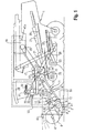
- FIG. 1 denotes a self-propelled combine harvester having a cutting unit 2 for harvesting cereals, rape, soybeans, etc.
- the cutting unit 2 consists essentially of a cutter bar 3 receiving cutting table 4, followed by a cutting trough 5 in the direction of Erntegut Weg 1es.
- the schematic representation of the cutting table 4 and the cutting trough 5 are formed as a common unit. However, it is possible to separate the cutting table 4 from the cutting trough 5 and to arrange it in a longitudinally displaceable manner, whereby the distance between the cutter bar 3 and an intake worm 6 arranged in the cutting trough 5 can be varied.
- a reel 8 is guided over support arms 9 in the rear region of the cutting trough 5 at joints 7, wherein the height position of the reel 8 by means of hydraulic cylinders 10 formed adjusting elements is variable.
- the reel 8, whose speed is preferably continuously variable via a variator gear not shown in detail is and which, depending on the design of the support arms 9, also in the longitudinal direction of the combine 1 can be adjusted, in connection with the following FIGS. 2 and 3 will be explained in more detail.
- a feeder 11 connects, wherein the auger 6 concentrically over opposing worm spiral the crop over the entire width of the cutting trough 5 and passes through an opening in a rear wall 12 of the cutting trough 5 to the inclined conveyor 11.
- This has at least two mutually spaced chains 13, the cooperating with a bottom 14 of a conveyor channel conveyor bars 14a (see FIGS. 2 and 3 ) take up. That of the in the FIGS. 2 and 3 crops 14a detected crop is transported across the bottom 14 and enters a tangentially acted threshing 15, which consists of a Vorbenchungstrommel 16, a threshing drum 17 and a concave 18.
- the threshing unit 15 is driven by a drive motor 19 via a variator 20.
- This drive motor 19 is the only drive source of the combine harvester 1 and therefore drives, among other things, the entire cutting unit 2, the feederhouse 11, the threshing unit 15 and the subordinate tray shaker 21, screens 22, a cleaning fan 23, a preparation tray 24, a return tray 25, a tailings elevator 26, a grain tank elevator 27, and a transmission 28 associated with a drive axle.
- the combine harvester 1 has a driver's cab 29, within which an input unit 30 and a display 31 are arranged.
- both the display 31 and the input unit 30 communicate with a control unit 32 via data lines 33 and 34.
- the control unit 32 is preferably connected via a first signal line 35 to first transducers 36 and via a second signal line 37 to second transducers 38.
- further signal lines are shown in dashed lines, with the corresponding arrangement of transducers connected to them still being discussed separately.
- a sensor 44 for detecting an actual value of the height position of the reel 8 is arranged on at least one of the above-explained joints 7, the corresponding measured values being transmitted to the control unit 32 via a sensor line 45 and being processed therein.
- First transducers 36 are used to detect fluctuations in the Ernteguthnes inside the feederhouse 11, where they measure a deflection of at least one of the chains 13 of the feeder 11 relative to the bottom 14 and feed this value for determining the Erntegutmenge on the basis of a layer thickness of Erntegutstromes the control unit 32 .
- Second transducers 38 are arranged above the rear wall 12 and serve to detect any spillage losses that they detect and transmit signals derived therefrom to the control unit 32.
- the control unit 32 has at least one signal output, via which it controls a hydraulic actuator system, for example in the form of a directional control valve, by means of a control line 39.
- the following arrangements and functions of transducers can be provided for detecting the crop flow:
- the first sensor serves to determine the crop flow as a function of a stock level and stock density of the crop to be harvested and consists for this purpose of at least one crop sensor 40 arranged on the cutting unit 2 and a position sensor 41 which measures the respective vertical position of the cutting unit 2, the measured values of Halmgutsensors 40 are compared with those of the position sensor 41 in the control unit 32.
- the first transducer serves to determine the flow of crop as a function of a torque required to drive the auger 6 by means of a torque sensor 42. Due to the greater amount of Halmguts to be conveyed by the screw flights and entrainment of the auger 6, the absorbed torque, so that it can be deduced from fluctuations in the crop flow.
- the first measuring sensor is used to determine the flow of crop material as a function of a torque required at the drive of the threshing unit 15.
- a torque sensor 43 is arranged in a tangential threshing mechanism on the drive of the threshing cylinder 17 and / or the pre-acceleration drum 16.
- a corresponding determination of the crop flow via a torque sensor 43 is natural also possible on a threshing unit with axial drum.
- this method can be implemented with relatively little effort for detecting fluctuations in the crop flow. For example, in a drive of the threshing unit 15 via a belt variator occurring at the conical variator discs spring travel change can be used to determine the required torque. In addition, to determine the torque required in the threshing unit 15, the slip occurring in the corresponding belt drive can also be determined.
- FIG. 1 nor an alternative shown, in which the crop flow is determined by the engine load of the drive motor 19.
- a sensor 43a is provided, which detects in particular via an interface to the engine management corresponding data.
- this method assumes that the power consumption is monitored by the drive, ie by the transmission 28 so that in certain driving situations, such as driving on slopes, with increased driving resistance caused by sinking drive wheels, etc., no erroneous adjustment of the reel 8 becomes.
- the reel 8 consists of a plurality of spaced apart in the axial direction hexagonal support stars 46 which are mounted on a reel shaft 47 and receive at their vertices in the longitudinal direction of the reel 8 extending support beam 48.
- the support bars 48 provided with conveyor tines 49 are pivotally guided in the support stars 46, wherein during one revolution of the reel 8 via a not-shown cam gear, the position of the conveyor tines 49 is controlled such that this offset by an acute angle to a perpendicular in the Intervene stalk crops.
- the reel shaft 47 rotatably mounted on the support arms 9 also receives an output pulley 50, which is connected via a drive belt to a drive pulley 51.
- the support arms 9 are, as already in connection with the FIG. 1 explained, pivotally guided on joints 7 on the rear wall 12 of the cutting trough 5 and supported by the hydraulic cylinder 10 on the cutting unit 2. At least one of these joints 7, the sensor 44 for determining an actual value of the altitude of the Reel 8 arranged.
- the entire consisting of the cutting unit 2 and the inclined conveyor 11 unit is also supported by a not-shown at the exit end of the inclined conveyor 11 pivot bearing provided on the combine and for cutting height adjustment of the cutting unit 2 via a lifting cylinder 52 pivotally.
- FIG. 2 show two different crop heights of a crop with an upper range, in which the cereal ears and rape or soybean pods carrying fruit pods are.
- a large stock level is denoted by 53
- the reel 8 is adjusted with respect to the stock height 53 of the crop so that both the support beam 48 and the conveyor tines 49 deeply engage in the crop to be harvested, so that there is a strong reel support.
- This has the consequence that whole ears of corn or cereal grains or rapeseed or soybean from bursting pods as a sprout, which is indicated by arrows 55, are removed from the crop.
- the occurrence of spatter is detected by the second transducer 38 and signaled to the control unit 32, whereupon by means of the hydraulic cylinder 10, the reel 8 is raised to a higher position in which no spatter occurs.
- the height adjustment of the reel 8 is controlled as a function of Erntegutl, which compensated by means of a corresponding reel supports fluctuations in crop flow and thus to achieve a uniform utilization of the subsequent threshing and separating device at maximum without grain losses realizable harvest speed.
- the respective drive torque is to be detected at the pre-acceleration drum 16 or the threshing cylinder 17 by means of the first measuring transducer 36 and fed to the control unit 32. This ensures that, depending on the parameter "Erntegut Weg" the height adjustment of the reel 8 via the hydraulic cylinder 10 is varied.
- the corresponding signal characterizing the crop flow can also be transmitted via the control unit 32 to a longitudinal displacement of the reel 8 or its speed change cause, if such adjustment options are provided.
- FIG. 3 is designated at 56 a control range for the height adjustment of the reel 8.
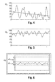
- FIGS. 4 and 5 show as diagrams the engine load of the drive motor 19, which is determined essentially by the fluctuations of the crop flow, wherein in each case on the ordinate the engine utilization M A and on the abscissa the time t is plotted.
- To FIG. 4 is operated with low reel support, whereby the average motor load M A decreases to a low value.
- the disadvantageous consequence of this is a low harvesting speed.
- after the FIG. 5 due to a higher reel support also a high average engine utilization M A the result. This also increases the harvesting speed.
- the FIG. 6 shows a diagram in which the crop flow fluctuations .DELTA.G F over the time t are plotted.
- crop flow fluctuations with a minimal fluctuation range ⁇ G Fmin are therefore to be regarded as having a low amplitude.
- FIG. 7 a possible embodiment of the CPU-containing display 31, the different fields for input or selected data, regarding the type of crop, its state, etc., the mode with which the reel control is operated, and data from the transducers according to the invention 36 and 38 and other sensors are detected, has. It can therefore be menu fields, operator display fields, result fields, etc. Of course, corresponding displays can also be integrated into existing displays on modern combine harvesters.
- FIG. 7 the input unit 30 and the control unit 32 in connection. With the illustrated input unit, after activating different menus, control processes can be activated.
- the control unit 32 further comprises a memory device 57 from which stored setting parameters can be retrieved.
- the first measuring transducer 36 for detecting the flow of crop material, the second measuring transducer 38 for detecting spray grain losses and the sensor 44 for actual values for the height position of the reel 8 are connected to the control unit.
- the control unit 32 is also in communication with a hydraulic control device 58 for the height adjustment of the reel 8 causing hydraulic cylinder 10, with a hydraulic control device 59 a speed adjustment of a variator for the reel drive and with a hydraulic control device 60 for a longitudinal adjustment of the reel 8. It is also conceivable, other functions in the field of To control cutting unit 2, which have an influence on the crop flow and possible grain losses.
Landscapes
- Life Sciences & Earth Sciences (AREA)
- Environmental Sciences (AREA)
- Outside Dividers And Delivering Mechanisms For Harvesters (AREA)
- Harvester Elements (AREA)
- Management, Administration, Business Operations System, And Electronic Commerce (AREA)
Applications Claiming Priority (1)
| Application Number | Priority Date | Filing Date | Title |
|---|---|---|---|
| DE201210106065 DE102012106065A1 (de) | 2012-07-06 | 2012-07-06 | Mähdrescher |
Publications (2)
| Publication Number | Publication Date |
|---|---|
| EP2681984A1 true EP2681984A1 (fr) | 2014-01-08 |
| EP2681984B1 EP2681984B1 (fr) | 2016-01-06 |
Family
ID=48190757
Family Applications (1)
| Application Number | Title | Priority Date | Filing Date |
|---|---|---|---|
| EP13165465.9A Active EP2681984B1 (fr) | 2012-07-06 | 2013-04-26 | Moissonneuse-batteuse |
Country Status (3)
| Country | Link |
|---|---|
| EP (1) | EP2681984B1 (fr) |
| DE (1) | DE102012106065A1 (fr) |
| HU (1) | HUE029725T2 (fr) |
Cited By (20)
| Publication number | Priority date | Publication date | Assignee | Title |
|---|---|---|---|---|
| EP3300580A1 (fr) * | 2016-09-30 | 2018-04-04 | CLAAS Selbstfahrende Erntemaschinen GmbH | Moissonneuse-batteuse pourvue de barre de coupe et dispositif de commande d'une barre de coupe |
| EP3403485A1 (fr) | 2017-05-18 | 2018-11-21 | Deere & Company | Dispositif d'auto-apprentissage, prenant en considération les entrées de correction destiné au contrôle automatique d'un paramètre de travail d'un dispositif de transport de produit de la récolte et/ou de traitement |
| CN109089527A (zh) * | 2018-11-02 | 2018-12-28 | 江苏农牧科技职业学院 | 一种智能收割机割台水平升降控制系统及方法 |
| EP3430881A1 (fr) | 2017-07-20 | 2019-01-23 | Deere & Company | Système pour optimiser des réglages de plate-forme sur la base d'une classification d'état de culture |
| US10209235B2 (en) | 2015-05-04 | 2019-02-19 | Deere & Company | Sensing and surfacing of crop loss data |
| WO2019055743A1 (fr) * | 2017-09-15 | 2019-03-21 | Cnh Industrial America Llc | Ensemble réglage de piste de came pour un rabatteur de récolte |
| EP3552474A1 (fr) | 2018-04-09 | 2019-10-16 | Deere & Company | Système pour commander un paramètre opérationnel d'une moissonneuse |
| WO2019234539A1 (fr) * | 2018-06-08 | 2019-12-12 | Agco Corporation | Hauteur automatique de bobine |
| CN111712127A (zh) * | 2018-04-10 | 2020-09-25 | 克拉斯自行式收获机械有限公司 | 联合收割机 |
| EP3766329A1 (fr) * | 2019-07-15 | 2021-01-20 | CLAAS Selbstfahrende Erntemaschinen GmbH | Engin d'abattage-façonnage agricole |
| EP3827656A1 (fr) * | 2019-11-27 | 2021-06-02 | CNH Industrial Belgium N.V. | Mesure laser montée sur une bobine de tête de moissonneuse |
| EP3858129A1 (fr) * | 2020-02-03 | 2021-08-04 | CLAAS Selbstfahrende Erntemaschinen GmbH | Ajustement de la longueur de table de coupe |
| EP3888444A1 (fr) * | 2020-04-03 | 2021-10-06 | CNH Industrial Belgium N.V. | Engagement entre rabatteur de tête de moissonneuse et récolte |
| CN113661827A (zh) * | 2021-08-16 | 2021-11-19 | 江苏大学 | 一种激光传感器的倒伏检测割台自适应装置及控制方法 |
| CN115119629A (zh) * | 2022-07-18 | 2022-09-30 | 山东理工大学 | 一种间隙可调式饲草收获机喂入装置 |
| EP4088560A1 (fr) * | 2021-05-10 | 2022-11-16 | AGCO International GmbH | Détection de perte de grain |
| EP4205528A1 (fr) | 2022-01-04 | 2023-07-05 | CNH Industrial Belgium N.V. | Réglage des paramètres de récolte sur un récolteur d'une moissonneuse-batteuse |
| EP4285706A1 (fr) * | 2022-06-01 | 2023-12-06 | CNH Industrial Belgium N.V. | Mesures de couple de bobine dans une machine agricole |
| RU2816642C2 (ru) * | 2019-07-15 | 2024-04-02 | КЛААС Зельбстфаренде Эрнтемашинен ГмбХ | Сельскохозяйственная уборочная машина |
| US20240114832A1 (en) * | 2022-10-11 | 2024-04-11 | Cnh Industrial America Llc | Agricultural system and method for monitoring feeder throughput of a harvester |
Families Citing this family (8)
| Publication number | Priority date | Publication date | Assignee | Title |
|---|---|---|---|---|
| DE102015113527A1 (de) | 2015-08-17 | 2017-02-23 | Claas Selbstfahrende Erntemaschinen Gmbh | Landwirtschaftliche Erntemaschine |
| AT522856B1 (de) * | 2019-06-27 | 2023-02-15 | Franz Schrattenecker | Schneidwerk für einen Mähdrescher |
| US11870973B2 (en) | 2021-07-27 | 2024-01-09 | Deere & Company | Camera calibration tool |
| US12477986B2 (en) | 2022-07-13 | 2025-11-25 | Deere & Company | Radar based cutting height system for a sugarcane harvester |
| DE102022133920A1 (de) | 2022-12-19 | 2024-06-20 | Claas Selbstfahrende Erntemaschinen Gmbh | Erntemaschine mit einem Kornverlustsensor umfassenden Erntevorsatzgerät |
| DE102023135792A1 (de) * | 2023-12-19 | 2025-06-26 | Claas Selbstfahrende Erntemaschinen Gmbh | Selbstfahrender Mähdrescher mit Haspeleingriffseinstellung |
| EP4666832A1 (fr) * | 2024-06-21 | 2025-12-24 | CNH Industrial Belgium N.V. | Commande de bobine pour une tête de récolte pour une moissonneuse-batteuse |
| EP4714250A1 (fr) * | 2024-09-18 | 2026-03-25 | CNH Industrial Belgium N.V. | Commande de vitesse d'alimentation de moissonneuse-batteuse |
Citations (5)
| Publication number | Priority date | Publication date | Assignee | Title |
|---|---|---|---|---|
| GB2173309A (en) * | 1985-04-02 | 1986-10-08 | Lundahl Inc Ezra C | Automatic sonar activated height control for a header |
| EP0812530A1 (fr) * | 1996-06-14 | 1997-12-17 | CLAAS KGaA | Moissonneuse à tablier à hauteur réglable |
| DE10339551A1 (de) | 2003-08-26 | 2005-04-14 | Claas Selbstfahrende Erntemaschinen Gmbh | Verfahren und Vorrichtung zur Steuerung eines höhenverstellbaren Schneidwerks |
| EP2143316A1 (fr) | 2008-07-09 | 2010-01-13 | CLAAS Selbstfahrende Erntemaschinen | Moissonneuse automobile |
| EP2517549A1 (fr) * | 2011-04-27 | 2012-10-31 | Deere & Company | Agencement et procédé de détection de la quantité de plantes sur un champ |
-
2012
- 2012-07-06 DE DE201210106065 patent/DE102012106065A1/de not_active Ceased
-
2013
- 2013-04-26 EP EP13165465.9A patent/EP2681984B1/fr active Active
- 2013-04-26 HU HUE13165465A patent/HUE029725T2/hu unknown
Patent Citations (5)
| Publication number | Priority date | Publication date | Assignee | Title |
|---|---|---|---|---|
| GB2173309A (en) * | 1985-04-02 | 1986-10-08 | Lundahl Inc Ezra C | Automatic sonar activated height control for a header |
| EP0812530A1 (fr) * | 1996-06-14 | 1997-12-17 | CLAAS KGaA | Moissonneuse à tablier à hauteur réglable |
| DE10339551A1 (de) | 2003-08-26 | 2005-04-14 | Claas Selbstfahrende Erntemaschinen Gmbh | Verfahren und Vorrichtung zur Steuerung eines höhenverstellbaren Schneidwerks |
| EP2143316A1 (fr) | 2008-07-09 | 2010-01-13 | CLAAS Selbstfahrende Erntemaschinen | Moissonneuse automobile |
| EP2517549A1 (fr) * | 2011-04-27 | 2012-10-31 | Deere & Company | Agencement et procédé de détection de la quantité de plantes sur un champ |
Cited By (39)
| Publication number | Priority date | Publication date | Assignee | Title |
|---|---|---|---|---|
| US10209235B2 (en) | 2015-05-04 | 2019-02-19 | Deere & Company | Sensing and surfacing of crop loss data |
| EP3300580B2 (fr) † | 2016-09-30 | 2022-04-27 | CLAAS Selbstfahrende Erntemaschinen GmbH | Moissonneuse-batteuse pourvue de barre de coupe et dispositif de commande d'une barre de coupe |
| EP3300580A1 (fr) * | 2016-09-30 | 2018-04-04 | CLAAS Selbstfahrende Erntemaschinen GmbH | Moissonneuse-batteuse pourvue de barre de coupe et dispositif de commande d'une barre de coupe |
| EP3300580B1 (fr) | 2016-09-30 | 2019-04-10 | CLAAS Selbstfahrende Erntemaschinen GmbH | Moissonneuse-batteuse pourvue de barre de coupe et dispositif de commande d'une barre de coupe |
| EP3403485A1 (fr) | 2017-05-18 | 2018-11-21 | Deere & Company | Dispositif d'auto-apprentissage, prenant en considération les entrées de correction destiné au contrôle automatique d'un paramètre de travail d'un dispositif de transport de produit de la récolte et/ou de traitement |
| DE102017208442A1 (de) | 2017-05-18 | 2018-11-22 | Deere & Company | Selbstlernende, Korrektureingaben berücksichtigende Anordnung zur selbsttätigen Kontrolle eines Arbeitsparameters einer Erntegutförder- und/oder -bearbeitungseinrichtung |
| US10925211B2 (en) | 2017-05-18 | 2021-02-23 | Deere & Company | Self-learning system that takes into account corrective inputs for automatic control of an operating parameter of a crop transport or processing device |
| EP3430881B1 (fr) | 2017-07-20 | 2020-07-29 | Deere & Company | Système pour optimiser des réglages de plate-forme sur la base d'une classification d'état de culture |
| EP3430881A1 (fr) | 2017-07-20 | 2019-01-23 | Deere & Company | Système pour optimiser des réglages de plate-forme sur la base d'une classification d'état de culture |
| US10757859B2 (en) | 2017-07-20 | 2020-09-01 | Deere & Company | System for optimizing platform settings based on crop state classification |
| WO2019055743A1 (fr) * | 2017-09-15 | 2019-03-21 | Cnh Industrial America Llc | Ensemble réglage de piste de came pour un rabatteur de récolte |
| US12010950B2 (en) | 2017-09-15 | 2024-06-18 | Cnh Industrial America Llc | Cam track adjustment assembly for a harvesting reel |
| EP3552474A1 (fr) | 2018-04-09 | 2019-10-16 | Deere & Company | Système pour commander un paramètre opérationnel d'une moissonneuse |
| US11483972B2 (en) | 2018-04-09 | 2022-11-01 | Deere & Company | System for controlling an operative parameter of a harvesting header |
| CN111712127A (zh) * | 2018-04-10 | 2020-09-25 | 克拉斯自行式收获机械有限公司 | 联合收割机 |
| US11903342B2 (en) | 2018-06-08 | 2024-02-20 | Agco Corporation | Auto reel height |
| WO2019234539A1 (fr) * | 2018-06-08 | 2019-12-12 | Agco Corporation | Hauteur automatique de bobine |
| CN109089527A (zh) * | 2018-11-02 | 2018-12-28 | 江苏农牧科技职业学院 | 一种智能收割机割台水平升降控制系统及方法 |
| CN109089527B (zh) * | 2018-11-02 | 2024-01-12 | 江苏农牧科技职业学院 | 一种智能收割机割台水平升降控制系统及方法 |
| EP3766329A1 (fr) * | 2019-07-15 | 2021-01-20 | CLAAS Selbstfahrende Erntemaschinen GmbH | Engin d'abattage-façonnage agricole |
| RU2816642C2 (ru) * | 2019-07-15 | 2024-04-02 | КЛААС Зельбстфаренде Эрнтемашинен ГмбХ | Сельскохозяйственная уборочная машина |
| US20210015040A1 (en) * | 2019-07-15 | 2021-01-21 | Claas Selbstfahrende Erntemaschinen Gmbh | Agricultural harvesting machine |
| US11596102B2 (en) * | 2019-07-15 | 2023-03-07 | Claas Selbstfahrende Erntemaschinen Gmbh | Agricultural harvesting machine |
| EP3827656A1 (fr) * | 2019-11-27 | 2021-06-02 | CNH Industrial Belgium N.V. | Mesure laser montée sur une bobine de tête de moissonneuse |
| US11793111B2 (en) | 2019-11-27 | 2023-10-24 | Cnh Industrial America Llc | Harvesting head reel-mounted laser measurement |
| EP3858129A1 (fr) * | 2020-02-03 | 2021-08-04 | CLAAS Selbstfahrende Erntemaschinen GmbH | Ajustement de la longueur de table de coupe |
| US11895950B2 (en) * | 2020-02-03 | 2024-02-13 | Claas Selbstfahrende Erntemaschinen Gmbh | System and method for cutting table length adaptation |
| EP3888444A1 (fr) * | 2020-04-03 | 2021-10-06 | CNH Industrial Belgium N.V. | Engagement entre rabatteur de tête de moissonneuse et récolte |
| US11659787B2 (en) * | 2020-04-03 | 2023-05-30 | Cnh Industrial America Llc | Harvesting head reel-crop engagement |
| US20210307248A1 (en) * | 2020-04-03 | 2021-10-07 | Cnh Industrial America Llc | Harvesting Head Reel-Crop Engagement |
| EP4088560A1 (fr) * | 2021-05-10 | 2022-11-16 | AGCO International GmbH | Détection de perte de grain |
| CN113661827B (zh) * | 2021-08-16 | 2022-07-22 | 江苏大学 | 一种激光传感器的倒伏检测割台自适应装置及控制方法 |
| CN113661827A (zh) * | 2021-08-16 | 2021-11-19 | 江苏大学 | 一种激光传感器的倒伏检测割台自适应装置及控制方法 |
| EP4205528A1 (fr) | 2022-01-04 | 2023-07-05 | CNH Industrial Belgium N.V. | Réglage des paramètres de récolte sur un récolteur d'une moissonneuse-batteuse |
| EP4285706A1 (fr) * | 2022-06-01 | 2023-12-06 | CNH Industrial Belgium N.V. | Mesures de couple de bobine dans une machine agricole |
| WO2023232728A1 (fr) * | 2022-06-01 | 2023-12-07 | Cnh Industrial Belgium N.V. | Mesures de couple de bobine dans un organe de coupe agricole |
| CN115119629A (zh) * | 2022-07-18 | 2022-09-30 | 山东理工大学 | 一种间隙可调式饲草收获机喂入装置 |
| US20240114832A1 (en) * | 2022-10-11 | 2024-04-11 | Cnh Industrial America Llc | Agricultural system and method for monitoring feeder throughput of a harvester |
| US12593751B2 (en) * | 2022-10-11 | 2026-04-07 | Cnh Industrial America Llc | Agricultural system and method for monitoring feeder throughput of a harvester |
Also Published As
| Publication number | Publication date |
|---|---|
| EP2681984B1 (fr) | 2016-01-06 |
| HUE029725T2 (hu) | 2017-03-28 |
| DE102012106065A1 (de) | 2014-01-09 |
Similar Documents
| Publication | Publication Date | Title |
|---|---|---|
| EP2681984B1 (fr) | Moissonneuse-batteuse | |
| EP3662741B1 (fr) | Machine de travail agricole ainsi que procédé de fonctionnement d'une machine de travail agricole | |
| EP3560314B1 (fr) | Mécanisme de coupe à réglage automatique de l'orientation de dent de rabatteur | |
| EP1281310B1 (fr) | Machine de récolte avec contrôle de la vitesse | |
| EP3494771B1 (fr) | Dispositif de hauteur de coupe automatique | |
| DE102004038404B4 (de) | Einrichtung zur selbsttätigen Einstellung der Schnitthöhe eines Erntevorsatzes zur Ernte stängelartiger Pflanzen | |
| EP2995190B1 (fr) | Procédé d'exploitation d'une moissonneuse-batteuse | |
| EP2687080A2 (fr) | Appareil frontal pour la récolte de maïs | |
| EP3659421B1 (fr) | Tête de récolte dotée de vis sans fin transversale réglable | |
| EP1982574B1 (fr) | Moissonneuse | |
| EP2863729B1 (fr) | Mécanisme de coupe | |
| EP3391724B1 (fr) | Appareil de paillage destiné au traitement de souches debout dans un champ ayant une position et/ou force d'appui au sol réglable | |
| EP3597027B1 (fr) | Moissonneuse-batteuse doté d'un convoyeur incliné pourvu de rouleau de déviation inférieur réglable | |
| EP2636297B1 (fr) | Moissonneuse automobile | |
| DE102017222587B4 (de) | Mulchgerät zur Bearbeitung von auf einem Feld stehenden Pflanzenstümpfen mit verstellbarer Position und/oder Bodenandruckkraft | |
| EP1790210B1 (fr) | Dispositif d'alimentation pour une faucheuse-hâcheuse | |
| EP3443833A1 (fr) | Chaîne cinématique destinée à l'entraînement d'une unité de travail d'une moissonneuse automotrice | |
| EP4252519B1 (fr) | Moissonneuse agricole et procédé de commande d'une moissonneuse agricole | |
| EP2168420B1 (fr) | Moissonneuse agricole | |
| BE1026594B1 (de) | Anordnung zur Einstellung der Position der Gegenschneide eines Feldhäckslers | |
| DE102012105881A1 (de) | Selbstfahrende landwirtschaftliche Arbeitsmaschine | |
| EP3794932A1 (fr) | Dispositif pivotant destiné à la distribution uniforme d'une marchandise sur un organe de transport et de nettoyage | |
| DE102013214561B4 (de) | Feldhäcksler mit einer Anordnung zur Höhensteuerung eines Vordruckbügels eines Erntevorsatzes | |
| DE102022119175A1 (de) | Schneidwerk für eine erntemaschine mit automatischer haspelfingerneigungseinstellung auf positionsbasis | |
| DE102021131109A1 (de) | Adaptereinheit zur Ankopplung eines Vorsatzgerätes an eine selbstfahrende Erntemaschine |
Legal Events
| Date | Code | Title | Description |
|---|---|---|---|
| PUAI | Public reference made under article 153(3) epc to a published international application that has entered the european phase |
Free format text: ORIGINAL CODE: 0009012 |
|
| AK | Designated contracting states |
Kind code of ref document: A1 Designated state(s): AL AT BE BG CH CY CZ DE DK EE ES FI FR GB GR HR HU IE IS IT LI LT LU LV MC MK MT NL NO PL PT RO RS SE SI SK SM TR |
|
| AX | Request for extension of the european patent |
Extension state: BA ME |
|
| 17P | Request for examination filed |
Effective date: 20140708 |
|
| RBV | Designated contracting states (corrected) |
Designated state(s): AL AT BE BG CH CY CZ DE DK EE ES FI FR GB GR HR HU IE IS IT LI LT LU LV MC MK MT NL NO PL PT RO RS SE SI SK SM TR |
|
| REG | Reference to a national code |
Ref country code: DE Ref legal event code: R079 Ref document number: 502013001733 Country of ref document: DE Free format text: PREVIOUS MAIN CLASS: A01D0041140000 Ipc: A01D0057020000 |
|
| GRAP | Despatch of communication of intention to grant a patent |
Free format text: ORIGINAL CODE: EPIDOSNIGR1 |
|
| RIC1 | Information provided on ipc code assigned before grant |
Ipc: A01D 41/14 20060101ALI20150824BHEP Ipc: A01D 57/02 20060101AFI20150824BHEP |
|
| INTG | Intention to grant announced |
Effective date: 20150923 |
|
| GRAS | Grant fee paid |
Free format text: ORIGINAL CODE: EPIDOSNIGR3 |
|
| GRAA | (expected) grant |
Free format text: ORIGINAL CODE: 0009210 |
|
| AK | Designated contracting states |
Kind code of ref document: B1 Designated state(s): AL AT BE BG CH CY CZ DE DK EE ES FI FR GB GR HR HU IE IS IT LI LT LU LV MC MK MT NL NO PL PT RO RS SE SI SK SM TR |
|
| REG | Reference to a national code |
Ref country code: GB Ref legal event code: FG4D Free format text: NOT ENGLISH |
|
| REG | Reference to a national code |
Ref country code: CH Ref legal event code: EP |
|
| REG | Reference to a national code |
Ref country code: IE Ref legal event code: FG4D Free format text: LANGUAGE OF EP DOCUMENT: GERMAN |
|
| REG | Reference to a national code |
Ref country code: AT Ref legal event code: REF Ref document number: 767995 Country of ref document: AT Kind code of ref document: T Effective date: 20160215 |
|
| REG | Reference to a national code |
Ref country code: DE Ref legal event code: R096 Ref document number: 502013001733 Country of ref document: DE |
|
| REG | Reference to a national code |
Ref country code: LT Ref legal event code: MG4D |
|
| REG | Reference to a national code |
Ref country code: NL Ref legal event code: MP Effective date: 20160106 |
|
| PG25 | Lapsed in a contracting state [announced via postgrant information from national office to epo] |
Ref country code: NL Free format text: LAPSE BECAUSE OF FAILURE TO SUBMIT A TRANSLATION OF THE DESCRIPTION OR TO PAY THE FEE WITHIN THE PRESCRIBED TIME-LIMIT Effective date: 20160106 |
|
| PG25 | Lapsed in a contracting state [announced via postgrant information from national office to epo] |
Ref country code: FI Free format text: LAPSE BECAUSE OF FAILURE TO SUBMIT A TRANSLATION OF THE DESCRIPTION OR TO PAY THE FEE WITHIN THE PRESCRIBED TIME-LIMIT Effective date: 20160106 Ref country code: HR Free format text: LAPSE BECAUSE OF FAILURE TO SUBMIT A TRANSLATION OF THE DESCRIPTION OR TO PAY THE FEE WITHIN THE PRESCRIBED TIME-LIMIT Effective date: 20160106 Ref country code: ES Free format text: LAPSE BECAUSE OF FAILURE TO SUBMIT A TRANSLATION OF THE DESCRIPTION OR TO PAY THE FEE WITHIN THE PRESCRIBED TIME-LIMIT Effective date: 20160106 Ref country code: NO Free format text: LAPSE BECAUSE OF FAILURE TO SUBMIT A TRANSLATION OF THE DESCRIPTION OR TO PAY THE FEE WITHIN THE PRESCRIBED TIME-LIMIT Effective date: 20160406 Ref country code: IT Free format text: LAPSE BECAUSE OF FAILURE TO SUBMIT A TRANSLATION OF THE DESCRIPTION OR TO PAY THE FEE WITHIN THE PRESCRIBED TIME-LIMIT Effective date: 20160106 Ref country code: GR Free format text: LAPSE BECAUSE OF FAILURE TO SUBMIT A TRANSLATION OF THE DESCRIPTION OR TO PAY THE FEE WITHIN THE PRESCRIBED TIME-LIMIT Effective date: 20160407 |
|
| PG25 | Lapsed in a contracting state [announced via postgrant information from national office to epo] |
Ref country code: RS Free format text: LAPSE BECAUSE OF FAILURE TO SUBMIT A TRANSLATION OF THE DESCRIPTION OR TO PAY THE FEE WITHIN THE PRESCRIBED TIME-LIMIT Effective date: 20160106 Ref country code: PL Free format text: LAPSE BECAUSE OF FAILURE TO SUBMIT A TRANSLATION OF THE DESCRIPTION OR TO PAY THE FEE WITHIN THE PRESCRIBED TIME-LIMIT Effective date: 20160106 Ref country code: LT Free format text: LAPSE BECAUSE OF FAILURE TO SUBMIT A TRANSLATION OF THE DESCRIPTION OR TO PAY THE FEE WITHIN THE PRESCRIBED TIME-LIMIT Effective date: 20160106 Ref country code: IS Free format text: LAPSE BECAUSE OF FAILURE TO SUBMIT A TRANSLATION OF THE DESCRIPTION OR TO PAY THE FEE WITHIN THE PRESCRIBED TIME-LIMIT Effective date: 20160506 Ref country code: LV Free format text: LAPSE BECAUSE OF FAILURE TO SUBMIT A TRANSLATION OF THE DESCRIPTION OR TO PAY THE FEE WITHIN THE PRESCRIBED TIME-LIMIT Effective date: 20160106 Ref country code: PT Free format text: LAPSE BECAUSE OF FAILURE TO SUBMIT A TRANSLATION OF THE DESCRIPTION OR TO PAY THE FEE WITHIN THE PRESCRIBED TIME-LIMIT Effective date: 20160506 Ref country code: SE Free format text: LAPSE BECAUSE OF FAILURE TO SUBMIT A TRANSLATION OF THE DESCRIPTION OR TO PAY THE FEE WITHIN THE PRESCRIBED TIME-LIMIT Effective date: 20160106 |
|
| REG | Reference to a national code |
Ref country code: DE Ref legal event code: R097 Ref document number: 502013001733 Country of ref document: DE |
|
| PG25 | Lapsed in a contracting state [announced via postgrant information from national office to epo] |
Ref country code: EE Free format text: LAPSE BECAUSE OF FAILURE TO SUBMIT A TRANSLATION OF THE DESCRIPTION OR TO PAY THE FEE WITHIN THE PRESCRIBED TIME-LIMIT Effective date: 20160106 Ref country code: DK Free format text: LAPSE BECAUSE OF FAILURE TO SUBMIT A TRANSLATION OF THE DESCRIPTION OR TO PAY THE FEE WITHIN THE PRESCRIBED TIME-LIMIT Effective date: 20160106 |
|
| PLBE | No opposition filed within time limit |
Free format text: ORIGINAL CODE: 0009261 |
|
| STAA | Information on the status of an ep patent application or granted ep patent |
Free format text: STATUS: NO OPPOSITION FILED WITHIN TIME LIMIT |
|
| PG25 | Lapsed in a contracting state [announced via postgrant information from national office to epo] |
Ref country code: RO Free format text: LAPSE BECAUSE OF FAILURE TO SUBMIT A TRANSLATION OF THE DESCRIPTION OR TO PAY THE FEE WITHIN THE PRESCRIBED TIME-LIMIT Effective date: 20160106 Ref country code: SK Free format text: LAPSE BECAUSE OF FAILURE TO SUBMIT A TRANSLATION OF THE DESCRIPTION OR TO PAY THE FEE WITHIN THE PRESCRIBED TIME-LIMIT Effective date: 20160106 Ref country code: CZ Free format text: LAPSE BECAUSE OF FAILURE TO SUBMIT A TRANSLATION OF THE DESCRIPTION OR TO PAY THE FEE WITHIN THE PRESCRIBED TIME-LIMIT Effective date: 20160106 Ref country code: SM Free format text: LAPSE BECAUSE OF FAILURE TO SUBMIT A TRANSLATION OF THE DESCRIPTION OR TO PAY THE FEE WITHIN THE PRESCRIBED TIME-LIMIT Effective date: 20160106 |
|
| RAP2 | Party data changed (patent owner data changed or rights of a patent transferred) |
Owner name: CLAAS SELBSTFAHRENDE ERNTEMASCHINEN GMBH |
|
| REG | Reference to a national code |
Ref country code: CH Ref legal event code: PL |
|
| 26N | No opposition filed |
Effective date: 20161007 |
|
| PG25 | Lapsed in a contracting state [announced via postgrant information from national office to epo] |
Ref country code: LU Free format text: LAPSE BECAUSE OF FAILURE TO SUBMIT A TRANSLATION OF THE DESCRIPTION OR TO PAY THE FEE WITHIN THE PRESCRIBED TIME-LIMIT Effective date: 20160426 |
|
| REG | Reference to a national code |
Ref country code: IE Ref legal event code: MM4A |
|
| REG | Reference to a national code |
Ref country code: FR Ref legal event code: ST Effective date: 20161230 |
|
| PG25 | Lapsed in a contracting state [announced via postgrant information from national office to epo] |
Ref country code: LI Free format text: LAPSE BECAUSE OF NON-PAYMENT OF DUE FEES Effective date: 20160430 Ref country code: CH Free format text: LAPSE BECAUSE OF NON-PAYMENT OF DUE FEES Effective date: 20160430 Ref country code: FR Free format text: LAPSE BECAUSE OF NON-PAYMENT OF DUE FEES Effective date: 20160502 |
|
| PG25 | Lapsed in a contracting state [announced via postgrant information from national office to epo] |
Ref country code: SI Free format text: LAPSE BECAUSE OF FAILURE TO SUBMIT A TRANSLATION OF THE DESCRIPTION OR TO PAY THE FEE WITHIN THE PRESCRIBED TIME-LIMIT Effective date: 20160106 Ref country code: BG Free format text: LAPSE BECAUSE OF FAILURE TO SUBMIT A TRANSLATION OF THE DESCRIPTION OR TO PAY THE FEE WITHIN THE PRESCRIBED TIME-LIMIT Effective date: 20160406 |
|
| REG | Reference to a national code |
Ref country code: HU Ref legal event code: AG4A Ref document number: E029725 Country of ref document: HU |
|
| PG25 | Lapsed in a contracting state [announced via postgrant information from national office to epo] |
Ref country code: IE Free format text: LAPSE BECAUSE OF NON-PAYMENT OF DUE FEES Effective date: 20160426 |
|
| GBPC | Gb: european patent ceased through non-payment of renewal fee |
Effective date: 20170426 |
|
| PG25 | Lapsed in a contracting state [announced via postgrant information from national office to epo] |
Ref country code: GB Free format text: LAPSE BECAUSE OF NON-PAYMENT OF DUE FEES Effective date: 20170426 |
|
| PG25 | Lapsed in a contracting state [announced via postgrant information from national office to epo] |
Ref country code: CY Free format text: LAPSE BECAUSE OF FAILURE TO SUBMIT A TRANSLATION OF THE DESCRIPTION OR TO PAY THE FEE WITHIN THE PRESCRIBED TIME-LIMIT Effective date: 20160106 |
|
| PG25 | Lapsed in a contracting state [announced via postgrant information from national office to epo] |
Ref country code: MT Free format text: LAPSE BECAUSE OF FAILURE TO SUBMIT A TRANSLATION OF THE DESCRIPTION OR TO PAY THE FEE WITHIN THE PRESCRIBED TIME-LIMIT Effective date: 20160106 Ref country code: TR Free format text: LAPSE BECAUSE OF FAILURE TO SUBMIT A TRANSLATION OF THE DESCRIPTION OR TO PAY THE FEE WITHIN THE PRESCRIBED TIME-LIMIT Effective date: 20160106 Ref country code: MC Free format text: LAPSE BECAUSE OF FAILURE TO SUBMIT A TRANSLATION OF THE DESCRIPTION OR TO PAY THE FEE WITHIN THE PRESCRIBED TIME-LIMIT Effective date: 20160106 Ref country code: MK Free format text: LAPSE BECAUSE OF FAILURE TO SUBMIT A TRANSLATION OF THE DESCRIPTION OR TO PAY THE FEE WITHIN THE PRESCRIBED TIME-LIMIT Effective date: 20160106 |
|
| PG25 | Lapsed in a contracting state [announced via postgrant information from national office to epo] |
Ref country code: AL Free format text: LAPSE BECAUSE OF FAILURE TO SUBMIT A TRANSLATION OF THE DESCRIPTION OR TO PAY THE FEE WITHIN THE PRESCRIBED TIME-LIMIT Effective date: 20160106 |
|
| REG | Reference to a national code |
Ref country code: AT Ref legal event code: MM01 Ref document number: 767995 Country of ref document: AT Kind code of ref document: T Effective date: 20180426 |
|
| PG25 | Lapsed in a contracting state [announced via postgrant information from national office to epo] |
Ref country code: AT Free format text: LAPSE BECAUSE OF NON-PAYMENT OF DUE FEES Effective date: 20180426 |
|
| P01 | Opt-out of the competence of the unified patent court (upc) registered |
Effective date: 20230515 |
|
| PGFP | Annual fee paid to national office [announced via postgrant information from national office to epo] |
Ref country code: DE Payment date: 20250422 Year of fee payment: 13 |
|
| PGFP | Annual fee paid to national office [announced via postgrant information from national office to epo] |
Ref country code: BE Payment date: 20250418 Year of fee payment: 13 |
|
| PGFP | Annual fee paid to national office [announced via postgrant information from national office to epo] |
Ref country code: HU Payment date: 20251008 Year of fee payment: 13 |