EP3443833A1 - Chaîne cinématique destinée à l'entraînement d'une unité de travail d'une moissonneuse automotrice - Google Patents
Chaîne cinématique destinée à l'entraînement d'une unité de travail d'une moissonneuse automotrice Download PDFInfo
- Publication number
- EP3443833A1 EP3443833A1 EP18168429.1A EP18168429A EP3443833A1 EP 3443833 A1 EP3443833 A1 EP 3443833A1 EP 18168429 A EP18168429 A EP 18168429A EP 3443833 A1 EP3443833 A1 EP 3443833A1
- Authority
- EP
- European Patent Office
- Prior art keywords
- drive
- drive train
- clutch
- belt
- pressure
- Prior art date
- Legal status (The legal status is an assumption and is not a legal conclusion. Google has not performed a legal analysis and makes no representation as to the accuracy of the status listed.)
- Granted
Links
Images
Classifications
-
- F—MECHANICAL ENGINEERING; LIGHTING; HEATING; WEAPONS; BLASTING
- F16—ENGINEERING ELEMENTS AND UNITS; GENERAL MEASURES FOR PRODUCING AND MAINTAINING EFFECTIVE FUNCTIONING OF MACHINES OR INSTALLATIONS; THERMAL INSULATION IN GENERAL
- F16D—COUPLINGS FOR TRANSMITTING ROTATION; CLUTCHES; BRAKES
- F16D13/00—Friction clutches
- F16D13/76—Friction clutches specially adapted to incorporate with other transmission parts, i.e. at least one of the clutch parts also having another function, e.g. being the disc of a pulley
-
- A—HUMAN NECESSITIES
- A01—AGRICULTURE; FORESTRY; ANIMAL HUSBANDRY; HUNTING; TRAPPING; FISHING
- A01D—HARVESTING; MOWING
- A01D41/00—Combines, i.e. harvesters or mowers combined with threshing devices
- A01D41/12—Details of combines
- A01D41/1243—Devices for laying-out or distributing the straw
-
- A—HUMAN NECESSITIES
- A01—AGRICULTURE; FORESTRY; ANIMAL HUSBANDRY; HUNTING; TRAPPING; FISHING
- A01D—HARVESTING; MOWING
- A01D69/00—Driving mechanisms or parts thereof for harvesters or mowers
- A01D69/08—Clutches
-
- A—HUMAN NECESSITIES
- A01—AGRICULTURE; FORESTRY; ANIMAL HUSBANDRY; HUNTING; TRAPPING; FISHING
- A01D—HARVESTING; MOWING
- A01D75/00—Accessories for harvesters or mowers
- A01D75/18—Safety devices for parts of the machines
- A01D75/182—Avoiding overload
-
- F—MECHANICAL ENGINEERING; LIGHTING; HEATING; WEAPONS; BLASTING
- F16—ENGINEERING ELEMENTS AND UNITS; GENERAL MEASURES FOR PRODUCING AND MAINTAINING EFFECTIVE FUNCTIONING OF MACHINES OR INSTALLATIONS; THERMAL INSULATION IN GENERAL
- F16D—COUPLINGS FOR TRANSMITTING ROTATION; CLUTCHES; BRAKES
- F16D13/00—Friction clutches
- F16D13/22—Friction clutches with axially-movable clutching members
- F16D13/38—Friction clutches with axially-movable clutching members with flat clutching surfaces, e.g. discs
- F16D13/40—Friction clutches with axially-movable clutching members with flat clutching surfaces, e.g. discs in which the or each axially-movable member is pressed exclusively against an axially-located member
-
- F—MECHANICAL ENGINEERING; LIGHTING; HEATING; WEAPONS; BLASTING
- F16—ENGINEERING ELEMENTS AND UNITS; GENERAL MEASURES FOR PRODUCING AND MAINTAINING EFFECTIVE FUNCTIONING OF MACHINES OR INSTALLATIONS; THERMAL INSULATION IN GENERAL
- F16D—COUPLINGS FOR TRANSMITTING ROTATION; CLUTCHES; BRAKES
- F16D7/00—Slip couplings, e.g. slipping on overload, for absorbing shock
- F16D7/02—Slip couplings, e.g. slipping on overload, for absorbing shock of the friction type
- F16D7/024—Slip couplings, e.g. slipping on overload, for absorbing shock of the friction type with axially applied torque limiting friction surfaces
- F16D7/025—Slip couplings, e.g. slipping on overload, for absorbing shock of the friction type with axially applied torque limiting friction surfaces with flat clutching surfaces, e.g. discs
-
- F—MECHANICAL ENGINEERING; LIGHTING; HEATING; WEAPONS; BLASTING
- F16—ENGINEERING ELEMENTS AND UNITS; GENERAL MEASURES FOR PRODUCING AND MAINTAINING EFFECTIVE FUNCTIONING OF MACHINES OR INSTALLATIONS; THERMAL INSULATION IN GENERAL
- F16H—GEARING
- F16H7/00—Gearings for conveying rotary motion by endless flexible members
- F16H7/08—Means for varying tension of belts, ropes or chains
- F16H7/10—Means for varying tension of belts, ropes or chains by adjusting the axis of a pulley
- F16H7/12—Means for varying tension of belts, ropes or chains by adjusting the axis of a pulley of an idle pulley
- F16H7/1254—Means for varying tension of belts, ropes or chains by adjusting the axis of a pulley of an idle pulley without vibration damping means
- F16H7/1281—Means for varying tension of belts, ropes or chains by adjusting the axis of a pulley of an idle pulley without vibration damping means where the axis of the pulley moves along a substantially circular path
-
- F—MECHANICAL ENGINEERING; LIGHTING; HEATING; WEAPONS; BLASTING
- F16—ENGINEERING ELEMENTS AND UNITS; GENERAL MEASURES FOR PRODUCING AND MAINTAINING EFFECTIVE FUNCTIONING OF MACHINES OR INSTALLATIONS; THERMAL INSULATION IN GENERAL
- F16H—GEARING
- F16H7/00—Gearings for conveying rotary motion by endless flexible members
- F16H7/08—Means for varying tension of belts, ropes or chains
- F16H2007/0802—Actuators for final output members
- F16H2007/0806—Compression coil springs
-
- F—MECHANICAL ENGINEERING; LIGHTING; HEATING; WEAPONS; BLASTING
- F16—ENGINEERING ELEMENTS AND UNITS; GENERAL MEASURES FOR PRODUCING AND MAINTAINING EFFECTIVE FUNCTIONING OF MACHINES OR INSTALLATIONS; THERMAL INSULATION IN GENERAL
- F16H—GEARING
- F16H7/00—Gearings for conveying rotary motion by endless flexible members
- F16H7/08—Means for varying tension of belts, ropes or chains
- F16H2007/0863—Finally actuated members, e.g. constructional details thereof
- F16H2007/0865—Pulleys
-
- F—MECHANICAL ENGINEERING; LIGHTING; HEATING; WEAPONS; BLASTING
- F16—ENGINEERING ELEMENTS AND UNITS; GENERAL MEASURES FOR PRODUCING AND MAINTAINING EFFECTIVE FUNCTIONING OF MACHINES OR INSTALLATIONS; THERMAL INSULATION IN GENERAL
- F16H—GEARING
- F16H7/00—Gearings for conveying rotary motion by endless flexible members
- F16H7/08—Means for varying tension of belts, ropes or chains
- F16H2007/0889—Path of movement of the finally actuated member
- F16H2007/0893—Circular path
Definitions
- the present invention relates to a drive train for driving a working aggregate of a self-propelled harvester according to the preamble of claim 1 and to a self-propelled harvester according to the preamble of claim 9.
- the drive train comprising a belt drive serves to drive a radial distributor of a combine harvester.
- the radial distributor comprises two rotatably driven runners.
- a drive belt connecting a drive pulley and a driven pulley is drivingly coupled by means of a hydraulically actuated coupling cylinder.
- additional bandages are required as belt guides.
- the driven pulley of the belt drive is connected by a drive shaft drivingly connected to the radial distributor.
- the drive shaft opens into a first gear stage of the first rotor. From the first gear stage is another wave, which opens into a second gear stage of the second rotor.
- a dry friction clutch is provided on a transmission input shaft of an input gear.
- Object of the present invention is to provide a drive train for a working unit of the type mentioned above, wherein the drive train is characterized by a simpler and space-reduced structure.
- a drive train for driving a working unit of a self-propelled harvesting machine comprising a switchable belt drive with a drive pulley and a driven pulley drivingly connecting drive belt, wherein the driven pulley of the belt drive is connected by a drive shaft drivingly connected to the working unit.
- the drive train comprises a clutch system which combines the functions of a belt clutch and an overload clutch in a structural unit, and that the response of the clutch system is hydraulically adjustable.
- the EP2 839 729 B1 can be dispensed with the dome cylinder, the friction clutch and bandages for belt guide.
- the belt tension remains permanent maintained, which extends the life of the belt.
- the hydraulic adjustability of the response of the clutch system realizes the function of the overload protection characterized in that a voltage applied to the clutch system hydraulic pressure, hereafter referred to as clutch pressure, can be limited in its maximum that when exceeding the set maximum clutch pressure equivalent torque slips the overload clutch. This slip limit is adjustable by means of different maximum pressure levels and thus reduces the complexity.
- the coupling system can be designed as a hydraulically switched, spring-returnable single-disc dry clutch with a housing section designed as a driven pulley.
- the components that implement the switching and the overload protection are arranged in a housing, so that the influence of pollution and weather is reduced.
- Another advantage results from the size of the single-disc dry clutch, which allows a high energy consumption, so that the slip time of the clutch or the wear is reduced.
- the integration of the driven pulley in a single-disc dry clutch receiving housing simplifies the structure, the housing protects the single-disc dry clutch from the weather or pollution.
- the single-disc dry clutch can have a pressurizable section.
- the pressurisable section is loaded or unloaded with the adjustable clutch pressure. Upon appropriate action on the section with the clutch pressure, the torque transmission takes place frictionally.
- the pressure applied to the pressurizable portion, provided by a pressure source, hydraulic pressure in response to at least one operating parameter of the working unit can be controlled.
- this hydraulic pressure referred to as the clutch pressure by means of a Switching valve arrangement can be varied.
- a directly controlled or pilot-controlled pressure relief valve could be provided in order to be able to adapt the clutch pressure to the at least one operating parameter.
- operating parameters in particular the drive torque and / or the drive speed of the working unit in question.
- an existing hydraulic or a separate hydraulic pump come into consideration, the latter can also serve to drive at least one other working unit.
- an adjustable pressure relief valve may be provided for controlling or regulating the clutch pressure.
- a spring-loaded belt tensioning device can be provided for pretensioning the drive belt.
- the provision of a simpler construction belt tensioner is sufficient.
- a spring-loaded belt tensioning device is cheaper.
- a mechanical brake can be integrated into the drive train. This has the advantage that a long overrun of the driven working unit can be avoided. This is particularly important against the background of the reliability of the working aggregate.
- the working unit can be designed as a radial distributor.
- the radial distributor serves for the application of chopped straw over the working width of an attachment arranged on the harvesting machine.
- the radial distributor is adapted to be transferred to a so-called swathing position to deposit the straw taken up by the harvester in the form of swaths.
- the coupling system according to the invention satisfies both operating situations of such a radial distributor by providing, in distribution mode, in addition to the torque transmission, the overload protection function, for example, when an occurrence of a blockage in one of the runners, met and interrupts the drive train in Schwadablage des.
- the radial distributor can have at least two runners.
- the radial distributor of a self-propelled harvester has at least two driven runners which serve to distribute chopped straw across the working width of an attachment arranged on the harvester.
- the radial distributor can also be designed with a total of four runners. Accordingly, the required clutch pressure can be adapted to the different variants of the radial distributor, without having to resize the single-disc dry clutch.
- a self-propelled harvester with a working unit designed as a radial distributor, a pressure source and a control device, wherein the self-propelled harvester comprises a drive train for driving the radial distributor according to one of claims 1 to 8.
- the control device can preferably be set up to control the hydraulic pressure applied to the pressurizable section in order to set the response of the overload clutch.
- the overload function by means of the clutch pressure to the design of the radial distributor, two or four runners, the drive speed of the rotor and the wear of the coupling system can be adjusted.
- control device may be configured to perform the control of the applied hydraulic pressure as a function of at least one crop property.
- the operating behavior of the rotor of the radial distributor is determined inter alia by the good properties of the crop to be distributed, including the throughput, the moisture, the Humbleselgutin and also the fruit type count. These crop properties can be used for the continuous adaptation of the hydraulically adjusted overload torque.
- control device may be configured to perform the control of the applied hydraulic pressure as a function of at least one operating parameter of the radial distributor.
- a torque peak occurring in the drive train during start-up of the radial distributor can be taken into account in the control of the clutch pressure.
- This can be achieved by depositing at least one corresponding switch-on routine or a pressure curve in the control device, which temporarily leads to the activation of a high clutch pressure.
- This switch-on routine is selected by the control device when the radial distributor is switched on or before it is engaged by the coupling system.
- the clutch pressure is lowered to a lower level based on at least one overload routine that can be stored in the control device, which corresponds to the desired overload torque, which is dependent, inter alia, on crop characteristics.
- the switch-on and overload routines can take into account different configurations or variants of the radial distributor in the control of the clutch system.
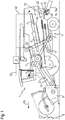
- Fig.1 shows the side view of a combine harvester 1 designed as a harvester with several working units such as a known per se and therefore not described here threshing 2 and this downstream as Horden presentler running separator 3.
- a cleaning device 4 consisting of a cleaning fan. 5 and at least two superposed sieves, upper sieve 6 and lower sieve 7.
- the invention is expressly not limited to such types of combine harvester, but also refers, for example, to combine with Axialabscheiderotoren as a separating organ and combine with axially arranged threshing separation device.
- a cutting unit 9 is arranged on the combine harvester 1, with the harvested crop 8 to be harvested cut and picked up.
- the cutting unit 9 feeds the crop 8 to a feeder 10, which is arranged on the front of the combine harvester 1.
- the inclined conveyor 10 transfers the crop 8 to the arranged in the machine housing 11 threshing 2 for expressing.
- a detection device 21 for determining the Erntegut besatzes is arranged in the inclined conveyor 10.
- a layer height sensor is usually provided, which determines the current throughput of recorded crop 8.
- a predominantly consisting of grains grain-chaff mixture is by a or more concave 12 of the threshing unit 2 deposited and passes through a preparation tray 13 to the cleaning device 5 to separate the grains from the non-grain components, that is from Halm former and spreader parts.
- a moisture sensor 22 arranged in the material flow path detects the moisture of the crop.
- threshing 2 In the rear region of the threshing 2 is associated with a rotating turning drum, which assumes the emerging from the threshing 2, consisting essentially of threshed crops Gutstrom and the separator 3 feeds, which promotes the flow of material in the rear region of the combine 1. In this case, the grains are still present in the flow and short straw and chaff are separated by passing from the separator 3 on a return tray 14.
- the return tray 14 transports the grains, short straw and chaff to the preparation tray 13.
- the crop From the preparation soil 13, the crop enters the cleaning device 4, in which the grains are separated from the short straw and from the chaff by means of the oscillatingly driven sieves 6, 7.
- straw reaches the rear end of the combine harvester 1, where it is fed to a chopper device 15 and to a distribution device 16 arranged downstream thereof as further working aggregates of the combine harvester 1.
- the chopping device 15 has inter alia a rotating chopper drum 17, which is mounted in a chopper housing 20.
- the chopper drum 17 is occupied with movable knives 18, which mesh with the chopper housing 20 fixed counter knives 19. With these knives 18 and the counter knives 19, the straw is shredded to shredded material and accelerated.
- the distribution device 16 is designed as a radial distributor 16a.
- the radial distributor 16a comprises at least two rotatably driven runners which distribute the chopped material flow over the width of the attachment 9 on the field floor.
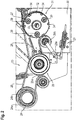
- FIG. 2 shows a schematic partial view of a drive train 23 of the distribution device 16 of the combine harvester 1 designed as a radial distributor 16a.
- a stage drive 24 having two pulleys 24a, 24b drives a counter stage 25 with a drive pulley 25a through a belt 26.
- the drive pulley 25a of the countershaft stage 25 is operatively connected by a drive belt 28 to an output pulley 27.
- a tensioning device 29 biases the drive belt 28.
- the clamping device 29 is supported for this purpose on a housing 30 of the distributor 16 from.
- the tensioning device 29 comprises a pressure roller 29b which is pressed against the drive belt 28 by a lever arrangement 29a acted upon by a spring force.
- the driven pulley 27 is formed on the outer circumferential surface of a housing 32 of a single-disc dry clutch 31, which forms a coupling system of the drive train 23.
- the single-disc dry clutch 31 is hydraulically actuated, for which purpose a hydraulic connection 33 is provided thereon.
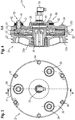
- FIG. 3 is a front view of the coupling system shown.
- the illustration shows the housing 32 of the single-disc dry clutch 31 and the driven pulley 27 arranged or formed on its lateral surface.
- the representation in FIG. 4 shows a sectional view of the single-disc dry clutch 31 along the line AA according to FIG. 3 ,
- the housing 32 includes a first housing portion 32a and a second housing portion 32b.
- the first housing portion 32 a and the second housing portion 32 b are connected to each other by screws 34.
- the first housing portion 32a is on a shaft 35 rotatably supported by a rolling bearing assembly 35a.
- a clutch disc 36 is arranged, which is positively connected by means of a toothing with this and displaceable in the axial direction.
- the clutch disc 36 has a friction lining 37. Coaxial with the clutch disc 36 is also a displaceable in the axial direction pressure plate 38 is arranged.
- the pressure plate 38 is connected to the second housing portion 32 b by prestressed screw 39.
- the respective screw 39 comprises a bushing 40 which extends through a through hole 41 of the second housing portion 32b.
- a compression spring 42 is arranged, which is supported on the second housing portion 32b and a flange 40 arranged at the free end of the sleeve 40 portion 43.
- a connection screw 44 received by the bush 40 is screwed into a threaded portion 45 of the pressure plate 38.
- three screw 39 are offset from one another at an angle of 120 ° in the circumferential direction.
- the pressure plate 38 has a piston-shaped portion 46, which can be acted upon by the hydraulic connection 33 with a hydraulic pressure or clutch pressure.
- the lateral surface of the piston-shaped section 46 is sealed off from the second housing section 32b by a sealing ring 47. If the piston-shaped portion 46 of the pressure plate 38 is acted upon by a clutch pressure, the clutch disc 36 is pressed with its friction lining 37 against the first housing portion 32a. If the piston-shaped portion 46 is depressurized, i. If there is no clutch pressure at the hydraulic connection 33, the pressure plate 38 is kept at a distance from the first housing section 32a due to the restoring force of the compression springs 42, so that no frictional connection occurs between the coupling disc 36 and the first housing section 32a.
- the single-disc dry clutch 31 combines the function of coupling, in which the torque transmission is produced by the pressurization of the piston-shaped portion 46 by frictional engagement, with the function overload protection by the voltage applied to the piston-shaped portion 46 maximum hydraulic Pressure is limited so that when exceeding the maximum hydraulic pressure equivalent torque, the single-disc dry clutch 31 slips.
- This slip limit can be adjusted by means of various maximum pressure levels and thus reduces the complexity of various drive variants of the distribution device 16.
- the distribution device 16 embodied as a radial distributor 16a, this means that depending on the number of runners provided, two runners or four runners, only the maximum pressure level must be adjusted while the single-disc dry clutch 31 remains structurally unchanged.
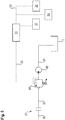
- FIG. 4 is greatly simplifies a circuit diagram illustrating the control of the coupling system.
- a designed as a hydraulic pump 48 pressure source is fed from a tank T with hydraulic oil. Through a hydraulic line 50, the hydraulic oil passes to the hydraulic port 33 of the single-disc dry clutch 31 to pressurize the piston-shaped portion 46.
- a pressure limiting valve 49 makes it possible to set the maximum hydraulic pressure at various values, with which the piston-shaped portion 46 is acted upon.
- the pressure relief valve 49 can be controlled by a control device 51, with which the pressure relief valve 49 is signal-technically connected by a signal and control line 52.
- the pressure source may be as in Fig. 4 shown to act a separate hydraulic pump 48.
- a hydraulic pressure provided by a working hydraulics, in particular a constant pressure system, of the combine harvester 1 may be used to actuate the single-disc dry clutch 31 of the clutch system.
- the control device 51 is connected by other signal and control lines 52 with the detection device 21 for detecting the Erntegut besatzes and the humidity sensor 22 by signal technology.
- the crop-specific signals provided by the detection device 21 and the moisture sensor 22 are evaluated by the control device 51.
- the control of the pressure limiting valve 49 for setting the maximum hydraulic pressure takes place as a function of at least one of these crop specific parameters throughput and or moisture.
- Another crop specific parameter is the shredded material length, which can be determined from the respective drive speed of the chopper device 15.
- a speed sensor 53 is provided, the signals of which can be supplied to the control device 51 for evaluation by means of the signal and control line 52.
- the control device 51 is configured to perform the control of the applied hydraulic pressure as a function of at least one operating parameter of the distribution device 16.
- the operating parameters include, as already stated, the number of runners of the radial distributor 16a.
- different pressure profiles can be stored in the control device 51, which are used when engaging the single-disc dry clutch 31 during start-up of the radial distributor 16a and during operation.
- a higher maximum hydraulic pressure can be preset by activation of the pressure-limiting valve 49, so that an occurring torque peak is compensated.
- a maximum hydraulic pressure is set by the actuation of the pressure limiting valve 49, which corresponds to the desired overload torque.
- the continuous sensory detection of crop-specific parameters allows continuous adjustment of the set overload torque by the control device 51 as a function of at least one crop quality such as crop, moisture, throughput and / or shred length.
Landscapes
- Engineering & Computer Science (AREA)
- General Engineering & Computer Science (AREA)
- Life Sciences & Earth Sciences (AREA)
- Environmental Sciences (AREA)
- Mechanical Engineering (AREA)
- Harvester Elements (AREA)
Applications Claiming Priority (1)
| Application Number | Priority Date | Filing Date | Title |
|---|---|---|---|
| DE102017118858.4A DE102017118858A1 (de) | 2017-08-18 | 2017-08-18 | Antriebsstrang zum Antreiben eines Arbeitsaggregates einer selbstfahrenden Erntemaschine |
Publications (2)
| Publication Number | Publication Date |
|---|---|
| EP3443833A1 true EP3443833A1 (fr) | 2019-02-20 |
| EP3443833B1 EP3443833B1 (fr) | 2021-07-28 |
Family
ID=62044541
Family Applications (1)
| Application Number | Title | Priority Date | Filing Date |
|---|---|---|---|
| EP18168429.1A Active EP3443833B1 (fr) | 2017-08-18 | 2018-04-20 | Moissonneuse automotrice équipée d'une chaîne cinématique destinée à l'entraînement d'une unité de travail |
Country Status (3)
| Country | Link |
|---|---|
| US (1) | US10830287B2 (fr) |
| EP (1) | EP3443833B1 (fr) |
| DE (1) | DE102017118858A1 (fr) |
Families Citing this family (6)
| Publication number | Priority date | Publication date | Assignee | Title |
|---|---|---|---|---|
| US11009105B2 (en) * | 2018-01-02 | 2021-05-18 | Agco Corporation | Easy adjust tensioner assembly |
| US10694671B2 (en) * | 2018-04-19 | 2020-06-30 | Cnh Industrial America Llc | Header with multiple row elements |
| US11596105B2 (en) | 2019-10-30 | 2023-03-07 | Cnh Industrial America Llc | Drive system for an agricultural baler |
| US11589514B2 (en) | 2019-10-30 | 2023-02-28 | Cnh Industrial America Llc | Pickup drive system for an agricultural baler |
| JP7337040B2 (ja) * | 2020-12-18 | 2023-09-01 | 株式会社クボタ | コンバイン |
| GB202219845D0 (en) * | 2022-12-30 | 2023-02-15 | Agco Int Gmbh | Reversible belt drive system |
Citations (3)
| Publication number | Priority date | Publication date | Assignee | Title |
|---|---|---|---|---|
| EP0207685A1 (fr) * | 1985-07-01 | 1987-01-07 | Borg-Warner Automotive, Inc. | Dispositif d'embrayage de démarrage pour une transmission continue variable |
| DE102009014101A1 (de) * | 2009-03-20 | 2010-09-23 | Sms Siemag Aktiengesellschaft | Sicherheitskupplung gegen Überlast, insbesondere für ein Walzgerüst oder eine Schere in einem Walzwerk |
| EP2839729B1 (fr) | 2013-08-19 | 2016-05-18 | CLAAS Selbstfahrende Erntemaschinen GmbH | Moissonneuse-batteuse équipée d'un dispositif de hache-paille |
Family Cites Families (25)
| Publication number | Priority date | Publication date | Assignee | Title |
|---|---|---|---|---|
| US2073146A (en) * | 1934-04-04 | 1937-03-09 | Gen Motors Corp | Clutch |
| US3217851A (en) * | 1962-01-23 | 1965-11-16 | Caterpillar Tractor Co | Fluid-actuated rotating clutch |
| GB1317744A (en) * | 1970-07-04 | 1973-05-23 | Girling Ltd | Disc brakes |
| US3789943A (en) * | 1971-10-12 | 1974-02-05 | Int Harvester Co | Vehicle drive and power control means |
| US4520912A (en) * | 1982-10-18 | 1985-06-04 | Borg-Warner Corporation | Hydraulically actuated starting clutch assembly |
| US4690662A (en) * | 1985-07-29 | 1987-09-01 | Shimano Industrial Company Limited | Speed control device |
| JPS62228749A (ja) * | 1986-03-27 | 1987-10-07 | Mitsuboshi Belting Ltd | 動力伝動装置 |
| US4856635A (en) * | 1987-09-29 | 1989-08-15 | Borg-Warner Automotive, Inc. | Starting clutch for a continuously variable transmission |
| US4964506A (en) * | 1988-04-29 | 1990-10-23 | Chrysler Corporation | Pressure balanced pistons in an automatic transmission |
| US4997074A (en) * | 1989-10-11 | 1991-03-05 | Borg-Warner Automotive Transmission & Engine Components Corporation | CVT hydraulic start clutch |
| GB2289201A (en) * | 1994-05-07 | 1995-11-15 | Ford New Holland Nv | Drive reversal for agricultural harvester |
| US5956998A (en) * | 1996-06-06 | 1999-09-28 | Fenelon; Paul J. | Stress reduction gear and apparatus using same |
| US5778644A (en) * | 1996-08-09 | 1998-07-14 | Deere & Company | Crop harvesting platform having a reversible drive for the reel, cutterbar center-feed augers and conditioner rolls |
| JP4663922B2 (ja) * | 2001-07-23 | 2011-04-06 | 株式会社ジェイテクト | 駆動力伝達装置 |
| US6708808B1 (en) * | 2002-09-11 | 2004-03-23 | General Motors Corporation | Torque-transmitting mechanism with a self-returning piston |
| DE10260196A1 (de) * | 2002-12-20 | 2004-07-01 | Bayerische Motoren Werke Ag | Verfahren zum Steuern einer schaltbaren Kupplung in einem Antriebsstrang eines Kraftfahrzeugs mit Vierradantrieb |
| JP4048487B2 (ja) * | 2003-03-07 | 2008-02-20 | トヨタ自動車株式会社 | ダンパ装置およびロックアップクラッチ装置 |
| US20060032722A1 (en) * | 2004-08-13 | 2006-02-16 | Guinter Joseph W | Retrofit hydraulic power take-off clutch |
| DE102005002880A1 (de) * | 2005-01-21 | 2006-08-17 | Deere & Company, Moline | Antriebsanordnung einer landwirtschaftlichen Arbeitsmaschine |
| US20060223640A1 (en) * | 2005-04-05 | 2006-10-05 | Bassett Michael L | Rotational coupling with overload protection |
| DE102007021732A1 (de) * | 2007-05-09 | 2008-11-20 | Agco Gmbh | Antriebssystem für Fahrzeuge mit mindestens zwei antreibbaren Fahrzeugachsen |
| US8066619B2 (en) * | 2008-04-19 | 2011-11-29 | Pt Tech, Inc | Clutch control system |
| JP5521596B2 (ja) * | 2009-05-12 | 2014-06-18 | 日産自動車株式会社 | 駆動力伝達装置 |
| GB2479566A (en) * | 2010-04-15 | 2011-10-19 | Agco Int Gmbh | Braking system for a rotating chopper drum of a forage harvester |
| BE1025046B1 (nl) * | 2017-03-10 | 2018-10-11 | Cnh Industrial Belgium Nv | Slipkoppeling voor een werkmachine |
-
2017
- 2017-08-18 DE DE102017118858.4A patent/DE102017118858A1/de not_active Withdrawn
-
2018
- 2018-04-20 EP EP18168429.1A patent/EP3443833B1/fr active Active
- 2018-06-12 US US16/006,191 patent/US10830287B2/en active Active
Patent Citations (3)
| Publication number | Priority date | Publication date | Assignee | Title |
|---|---|---|---|---|
| EP0207685A1 (fr) * | 1985-07-01 | 1987-01-07 | Borg-Warner Automotive, Inc. | Dispositif d'embrayage de démarrage pour une transmission continue variable |
| DE102009014101A1 (de) * | 2009-03-20 | 2010-09-23 | Sms Siemag Aktiengesellschaft | Sicherheitskupplung gegen Überlast, insbesondere für ein Walzgerüst oder eine Schere in einem Walzwerk |
| EP2839729B1 (fr) | 2013-08-19 | 2016-05-18 | CLAAS Selbstfahrende Erntemaschinen GmbH | Moissonneuse-batteuse équipée d'un dispositif de hache-paille |
Also Published As
| Publication number | Publication date |
|---|---|
| US10830287B2 (en) | 2020-11-10 |
| EP3443833B1 (fr) | 2021-07-28 |
| DE102017118858A1 (de) | 2019-02-21 |
| US20190055993A1 (en) | 2019-02-21 |
Similar Documents
| Publication | Publication Date | Title |
|---|---|---|
| EP3443833B1 (fr) | Moissonneuse automotrice équipée d'une chaîne cinématique destinée à l'entraînement d'une unité de travail | |
| EP3662741B2 (fr) | Machine de travail agricole ainsi que procédé de fonctionnement d'une machine de travail agricole | |
| EP2681984B1 (fr) | Moissonneuse-batteuse | |
| DE3048255C2 (de) | Antriebsvorrichtung für eine landwirtschaftlich genutzte Maschine, insbesondere Mähdrescher | |
| EP1847169B1 (fr) | Procédé et dispositif destinés au réglage de la longueur de coupe d'un dispositif de fourrage d'une moissonneuse agricole | |
| EP3395158B1 (fr) | Moissonneuse-batteuse | |
| EP2636297B1 (fr) | Moissonneuse automobile | |
| EP2995190B1 (fr) | Procédé d'exploitation d'une moissonneuse-batteuse | |
| EP2839729B2 (fr) | Moissonneuse-batteuse équipée d'un dispositif de hache-paille | |
| EP2687080A2 (fr) | Appareil frontal pour la récolte de maïs | |
| EP1825740A1 (fr) | Procédé et dispositif destinés à la détermination des propriétés de compactage de biens de récolte | |
| WO2017005852A1 (fr) | Dispositif d'unité de coupe | |
| EP2789222A1 (fr) | Système d'entraînement configuré sous forme d'entraînement à courroie d'une moissonneuse-batteuse automotrice | |
| EP2952087A1 (fr) | Système d'entraînement d'une moissonneuse automotrice | |
| EP3479674B1 (fr) | Moissonneuse agricole | |
| EP0727135B1 (fr) | Moissonneuse-batteuse | |
| EP3146833B1 (fr) | Machine agricole | |
| DE102004056233A1 (de) | Landwirtschaftliche Arbeitsmaschine mit einem Antriebsmotor | |
| DE19847891A1 (de) | Steuerung für Vorsatzgerät | |
| EP1066745B1 (fr) | Méthode et dispositif de commande pour les organes de travail et transport des machines récolteuses agricoles | |
| EP2965610B1 (fr) | Ramasseuse-hacheuse dotée d'une protection contre les surcharges | |
| DE4425453C1 (de) | Mähdrescher mit Gebläseregelung | |
| DE20001144U1 (de) | Landwirtschaftliche Erntemaschine | |
| EP2574227B1 (fr) | Moissonneuse automobile | |
| DE19926827C2 (de) | Antrieb für eine Kolbensammelpresse für landwirtschaftliche Erntegüter |
Legal Events
| Date | Code | Title | Description |
|---|---|---|---|
| PUAI | Public reference made under article 153(3) epc to a published international application that has entered the european phase |
Free format text: ORIGINAL CODE: 0009012 |
|
| STAA | Information on the status of an ep patent application or granted ep patent |
Free format text: STATUS: THE APPLICATION HAS BEEN PUBLISHED |
|
| AK | Designated contracting states |
Kind code of ref document: A1 Designated state(s): AL AT BE BG CH CY CZ DE DK EE ES FI FR GB GR HR HU IE IS IT LI LT LU LV MC MK MT NL NO PL PT RO RS SE SI SK SM TR |
|
| AX | Request for extension of the european patent |
Extension state: BA ME |
|
| STAA | Information on the status of an ep patent application or granted ep patent |
Free format text: STATUS: REQUEST FOR EXAMINATION WAS MADE |
|
| 17P | Request for examination filed |
Effective date: 20190820 |
|
| RBV | Designated contracting states (corrected) |
Designated state(s): AL AT BE BG CH CY CZ DE DK EE ES FI FR GB GR HR HU IE IS IT LI LT LU LV MC MK MT NL NO PL PT RO RS SE SI SK SM TR |
|
| STAA | Information on the status of an ep patent application or granted ep patent |
Free format text: STATUS: EXAMINATION IS IN PROGRESS |
|
| 17Q | First examination report despatched |
Effective date: 20200424 |
|
| GRAP | Despatch of communication of intention to grant a patent |
Free format text: ORIGINAL CODE: EPIDOSNIGR1 |
|
| STAA | Information on the status of an ep patent application or granted ep patent |
Free format text: STATUS: GRANT OF PATENT IS INTENDED |
|
| INTG | Intention to grant announced |
Effective date: 20210222 |
|
| GRAS | Grant fee paid |
Free format text: ORIGINAL CODE: EPIDOSNIGR3 |
|
| GRAA | (expected) grant |
Free format text: ORIGINAL CODE: 0009210 |
|
| STAA | Information on the status of an ep patent application or granted ep patent |
Free format text: STATUS: THE PATENT HAS BEEN GRANTED |
|
| AK | Designated contracting states |
Kind code of ref document: B1 Designated state(s): AL AT BE BG CH CY CZ DE DK EE ES FI FR GB GR HR HU IE IS IT LI LT LU LV MC MK MT NL NO PL PT RO RS SE SI SK SM TR |
|
| REG | Reference to a national code |
Ref country code: GB Ref legal event code: FG4D Free format text: NOT ENGLISH |
|
| REG | Reference to a national code |
Ref country code: CH Ref legal event code: EP |
|
| REG | Reference to a national code |
Ref country code: AT Ref legal event code: REF Ref document number: 1413863 Country of ref document: AT Kind code of ref document: T Effective date: 20210815 |
|
| REG | Reference to a national code |
Ref country code: IE Ref legal event code: FG4D Free format text: LANGUAGE OF EP DOCUMENT: GERMAN |
|
| REG | Reference to a national code |
Ref country code: DE Ref legal event code: R096 Ref document number: 502018006276 Country of ref document: DE |
|
| REG | Reference to a national code |
Ref country code: LT Ref legal event code: MG9D |
|
| REG | Reference to a national code |
Ref country code: NL Ref legal event code: MP Effective date: 20210728 |
|
| PG25 | Lapsed in a contracting state [announced via postgrant information from national office to epo] |
Ref country code: SE Free format text: LAPSE BECAUSE OF FAILURE TO SUBMIT A TRANSLATION OF THE DESCRIPTION OR TO PAY THE FEE WITHIN THE PRESCRIBED TIME-LIMIT Effective date: 20210728 Ref country code: RS Free format text: LAPSE BECAUSE OF FAILURE TO SUBMIT A TRANSLATION OF THE DESCRIPTION OR TO PAY THE FEE WITHIN THE PRESCRIBED TIME-LIMIT Effective date: 20210728 Ref country code: HR Free format text: LAPSE BECAUSE OF FAILURE TO SUBMIT A TRANSLATION OF THE DESCRIPTION OR TO PAY THE FEE WITHIN THE PRESCRIBED TIME-LIMIT Effective date: 20210728 Ref country code: ES Free format text: LAPSE BECAUSE OF FAILURE TO SUBMIT A TRANSLATION OF THE DESCRIPTION OR TO PAY THE FEE WITHIN THE PRESCRIBED TIME-LIMIT Effective date: 20210728 Ref country code: FI Free format text: LAPSE BECAUSE OF FAILURE TO SUBMIT A TRANSLATION OF THE DESCRIPTION OR TO PAY THE FEE WITHIN THE PRESCRIBED TIME-LIMIT Effective date: 20210728 Ref country code: NO Free format text: LAPSE BECAUSE OF FAILURE TO SUBMIT A TRANSLATION OF THE DESCRIPTION OR TO PAY THE FEE WITHIN THE PRESCRIBED TIME-LIMIT Effective date: 20211028 Ref country code: NL Free format text: LAPSE BECAUSE OF FAILURE TO SUBMIT A TRANSLATION OF THE DESCRIPTION OR TO PAY THE FEE WITHIN THE PRESCRIBED TIME-LIMIT Effective date: 20210728 Ref country code: PT Free format text: LAPSE BECAUSE OF FAILURE TO SUBMIT A TRANSLATION OF THE DESCRIPTION OR TO PAY THE FEE WITHIN THE PRESCRIBED TIME-LIMIT Effective date: 20211129 Ref country code: BG Free format text: LAPSE BECAUSE OF FAILURE TO SUBMIT A TRANSLATION OF THE DESCRIPTION OR TO PAY THE FEE WITHIN THE PRESCRIBED TIME-LIMIT Effective date: 20211028 Ref country code: LT Free format text: LAPSE BECAUSE OF FAILURE TO SUBMIT A TRANSLATION OF THE DESCRIPTION OR TO PAY THE FEE WITHIN THE PRESCRIBED TIME-LIMIT Effective date: 20210728 |
|
| PG25 | Lapsed in a contracting state [announced via postgrant information from national office to epo] |
Ref country code: PL Free format text: LAPSE BECAUSE OF FAILURE TO SUBMIT A TRANSLATION OF THE DESCRIPTION OR TO PAY THE FEE WITHIN THE PRESCRIBED TIME-LIMIT Effective date: 20210728 Ref country code: LV Free format text: LAPSE BECAUSE OF FAILURE TO SUBMIT A TRANSLATION OF THE DESCRIPTION OR TO PAY THE FEE WITHIN THE PRESCRIBED TIME-LIMIT Effective date: 20210728 Ref country code: GR Free format text: LAPSE BECAUSE OF FAILURE TO SUBMIT A TRANSLATION OF THE DESCRIPTION OR TO PAY THE FEE WITHIN THE PRESCRIBED TIME-LIMIT Effective date: 20211029 |
|
| PG25 | Lapsed in a contracting state [announced via postgrant information from national office to epo] |
Ref country code: DK Free format text: LAPSE BECAUSE OF FAILURE TO SUBMIT A TRANSLATION OF THE DESCRIPTION OR TO PAY THE FEE WITHIN THE PRESCRIBED TIME-LIMIT Effective date: 20210728 |
|
| REG | Reference to a national code |
Ref country code: DE Ref legal event code: R097 Ref document number: 502018006276 Country of ref document: DE |
|
| PG25 | Lapsed in a contracting state [announced via postgrant information from national office to epo] |
Ref country code: SM Free format text: LAPSE BECAUSE OF FAILURE TO SUBMIT A TRANSLATION OF THE DESCRIPTION OR TO PAY THE FEE WITHIN THE PRESCRIBED TIME-LIMIT Effective date: 20210728 Ref country code: SK Free format text: LAPSE BECAUSE OF FAILURE TO SUBMIT A TRANSLATION OF THE DESCRIPTION OR TO PAY THE FEE WITHIN THE PRESCRIBED TIME-LIMIT Effective date: 20210728 Ref country code: RO Free format text: LAPSE BECAUSE OF FAILURE TO SUBMIT A TRANSLATION OF THE DESCRIPTION OR TO PAY THE FEE WITHIN THE PRESCRIBED TIME-LIMIT Effective date: 20210728 Ref country code: EE Free format text: LAPSE BECAUSE OF FAILURE TO SUBMIT A TRANSLATION OF THE DESCRIPTION OR TO PAY THE FEE WITHIN THE PRESCRIBED TIME-LIMIT Effective date: 20210728 Ref country code: CZ Free format text: LAPSE BECAUSE OF FAILURE TO SUBMIT A TRANSLATION OF THE DESCRIPTION OR TO PAY THE FEE WITHIN THE PRESCRIBED TIME-LIMIT Effective date: 20210728 Ref country code: AL Free format text: LAPSE BECAUSE OF FAILURE TO SUBMIT A TRANSLATION OF THE DESCRIPTION OR TO PAY THE FEE WITHIN THE PRESCRIBED TIME-LIMIT Effective date: 20210728 |
|
| PLBE | No opposition filed within time limit |
Free format text: ORIGINAL CODE: 0009261 |
|
| STAA | Information on the status of an ep patent application or granted ep patent |
Free format text: STATUS: NO OPPOSITION FILED WITHIN TIME LIMIT |
|
| 26N | No opposition filed |
Effective date: 20220429 |
|
| PG25 | Lapsed in a contracting state [announced via postgrant information from national office to epo] |
Ref country code: IT Free format text: LAPSE BECAUSE OF FAILURE TO SUBMIT A TRANSLATION OF THE DESCRIPTION OR TO PAY THE FEE WITHIN THE PRESCRIBED TIME-LIMIT Effective date: 20210728 |
|
| REG | Reference to a national code |
Ref country code: CH Ref legal event code: PL |
|
| GBPC | Gb: european patent ceased through non-payment of renewal fee |
Effective date: 20220420 |
|
| PG25 | Lapsed in a contracting state [announced via postgrant information from national office to epo] |
Ref country code: MC Free format text: LAPSE BECAUSE OF FAILURE TO SUBMIT A TRANSLATION OF THE DESCRIPTION OR TO PAY THE FEE WITHIN THE PRESCRIBED TIME-LIMIT Effective date: 20210728 Ref country code: LU Free format text: LAPSE BECAUSE OF NON-PAYMENT OF DUE FEES Effective date: 20220420 Ref country code: LI Free format text: LAPSE BECAUSE OF NON-PAYMENT OF DUE FEES Effective date: 20220430 Ref country code: GB Free format text: LAPSE BECAUSE OF NON-PAYMENT OF DUE FEES Effective date: 20220420 Ref country code: CH Free format text: LAPSE BECAUSE OF NON-PAYMENT OF DUE FEES Effective date: 20220430 |
|
| PG25 | Lapsed in a contracting state [announced via postgrant information from national office to epo] |
Ref country code: IE Free format text: LAPSE BECAUSE OF NON-PAYMENT OF DUE FEES Effective date: 20220420 |
|
| P01 | Opt-out of the competence of the unified patent court (upc) registered |
Effective date: 20230516 |
|
| PG25 | Lapsed in a contracting state [announced via postgrant information from national office to epo] |
Ref country code: HU Free format text: LAPSE BECAUSE OF FAILURE TO SUBMIT A TRANSLATION OF THE DESCRIPTION OR TO PAY THE FEE WITHIN THE PRESCRIBED TIME-LIMIT; INVALID AB INITIO Effective date: 20180420 |
|
| PG25 | Lapsed in a contracting state [announced via postgrant information from national office to epo] |
Ref country code: MK Free format text: LAPSE BECAUSE OF FAILURE TO SUBMIT A TRANSLATION OF THE DESCRIPTION OR TO PAY THE FEE WITHIN THE PRESCRIBED TIME-LIMIT Effective date: 20210728 Ref country code: CY Free format text: LAPSE BECAUSE OF FAILURE TO SUBMIT A TRANSLATION OF THE DESCRIPTION OR TO PAY THE FEE WITHIN THE PRESCRIBED TIME-LIMIT Effective date: 20210728 |
|
| REG | Reference to a national code |
Ref country code: AT Ref legal event code: MM01 Ref document number: 1413863 Country of ref document: AT Kind code of ref document: T Effective date: 20230420 |
|
| PG25 | Lapsed in a contracting state [announced via postgrant information from national office to epo] |
Ref country code: AT Free format text: LAPSE BECAUSE OF NON-PAYMENT OF DUE FEES Effective date: 20230420 |
|
| PG25 | Lapsed in a contracting state [announced via postgrant information from national office to epo] |
Ref country code: AT Free format text: LAPSE BECAUSE OF NON-PAYMENT OF DUE FEES Effective date: 20230420 |
|
| PG25 | Lapsed in a contracting state [announced via postgrant information from national office to epo] |
Ref country code: MT Free format text: LAPSE BECAUSE OF FAILURE TO SUBMIT A TRANSLATION OF THE DESCRIPTION OR TO PAY THE FEE WITHIN THE PRESCRIBED TIME-LIMIT Effective date: 20210728 |
|
| PGFP | Annual fee paid to national office [announced via postgrant information from national office to epo] |
Ref country code: DE Payment date: 20250422 Year of fee payment: 8 |
|
| PGFP | Annual fee paid to national office [announced via postgrant information from national office to epo] |
Ref country code: BE Payment date: 20250418 Year of fee payment: 8 |
|
| PGFP | Annual fee paid to national office [announced via postgrant information from national office to epo] |
Ref country code: FR Payment date: 20250425 Year of fee payment: 8 |
|
| PG25 | Lapsed in a contracting state [announced via postgrant information from national office to epo] |
Ref country code: TR Free format text: LAPSE BECAUSE OF FAILURE TO SUBMIT A TRANSLATION OF THE DESCRIPTION OR TO PAY THE FEE WITHIN THE PRESCRIBED TIME-LIMIT Effective date: 20210728 |
|
| PGFP | Annual fee paid to national office [announced via postgrant information from national office to epo] |
Ref country code: AT Payment date: 20260410 Year of fee payment: 5 |