EP2682034B1 - Aspirateur à poussière doté d'un dispositif de réglage d'une puissance de ventilateur et procédé de fonctionnement d'un tel aspirateur à poussière - Google Patents
Aspirateur à poussière doté d'un dispositif de réglage d'une puissance de ventilateur et procédé de fonctionnement d'un tel aspirateur à poussière Download PDFInfo
- Publication number
- EP2682034B1 EP2682034B1 EP13401061.0A EP13401061A EP2682034B1 EP 2682034 B1 EP2682034 B1 EP 2682034B1 EP 13401061 A EP13401061 A EP 13401061A EP 2682034 B1 EP2682034 B1 EP 2682034B1
- Authority
- EP
- European Patent Office
- Prior art keywords
- vacuum cleaner
- suction
- acceleration sensor
- fan
- power
- Prior art date
- Legal status (The legal status is an assumption and is not a legal conclusion. Google has not performed a legal analysis and makes no representation as to the accuracy of the status listed.)
- Active
Links
Images





Classifications
-
- A—HUMAN NECESSITIES
- A47—FURNITURE; DOMESTIC ARTICLES OR APPLIANCES; COFFEE MILLS; SPICE MILLS; SUCTION CLEANERS IN GENERAL
- A47L—DOMESTIC WASHING OR CLEANING; SUCTION CLEANERS IN GENERAL
- A47L9/00—Details or accessories of suction cleaners, e.g. mechanical means for controlling the suction or for effecting pulsating action; Storing devices specially adapted to suction cleaners or parts thereof; Carrying-vehicles specially adapted for suction cleaners
- A47L9/28—Installation of the electric equipment, e.g. adaptation or attachment to the suction cleaner; Controlling suction cleaners by electric means
- A47L9/2805—Parameters or conditions being sensed
- A47L9/2831—Motor parameters, e.g. motor load or speed
-
- A—HUMAN NECESSITIES
- A47—FURNITURE; DOMESTIC ARTICLES OR APPLIANCES; COFFEE MILLS; SPICE MILLS; SUCTION CLEANERS IN GENERAL
- A47L—DOMESTIC WASHING OR CLEANING; SUCTION CLEANERS IN GENERAL
- A47L9/00—Details or accessories of suction cleaners, e.g. mechanical means for controlling the suction or for effecting pulsating action; Storing devices specially adapted to suction cleaners or parts thereof; Carrying-vehicles specially adapted for suction cleaners
- A47L9/28—Installation of the electric equipment, e.g. adaptation or attachment to the suction cleaner; Controlling suction cleaners by electric means
- A47L9/2836—Installation of the electric equipment, e.g. adaptation or attachment to the suction cleaner; Controlling suction cleaners by electric means characterised by the parts which are controlled
- A47L9/2842—Suction motors or blowers
-
- A—HUMAN NECESSITIES
- A47—FURNITURE; DOMESTIC ARTICLES OR APPLIANCES; COFFEE MILLS; SPICE MILLS; SUCTION CLEANERS IN GENERAL
- A47L—DOMESTIC WASHING OR CLEANING; SUCTION CLEANERS IN GENERAL
- A47L9/00—Details or accessories of suction cleaners, e.g. mechanical means for controlling the suction or for effecting pulsating action; Storing devices specially adapted to suction cleaners or parts thereof; Carrying-vehicles specially adapted for suction cleaners
- A47L9/28—Installation of the electric equipment, e.g. adaptation or attachment to the suction cleaner; Controlling suction cleaners by electric means
- A47L9/2857—User input or output elements for control, e.g. buttons, switches or displays
-
- A—HUMAN NECESSITIES
- A47—FURNITURE; DOMESTIC ARTICLES OR APPLIANCES; COFFEE MILLS; SPICE MILLS; SUCTION CLEANERS IN GENERAL
- A47L—DOMESTIC WASHING OR CLEANING; SUCTION CLEANERS IN GENERAL
- A47L9/00—Details or accessories of suction cleaners, e.g. mechanical means for controlling the suction or for effecting pulsating action; Storing devices specially adapted to suction cleaners or parts thereof; Carrying-vehicles specially adapted for suction cleaners
- A47L9/28—Installation of the electric equipment, e.g. adaptation or attachment to the suction cleaner; Controlling suction cleaners by electric means
- A47L9/2857—User input or output elements for control, e.g. buttons, switches or displays
- A47L9/2863—Control elements activated by pivoting movement of the upright vacuum cleaner handle
Definitions
- the invention relates to a vacuum cleaner with a device for adjusting a fan power of a suction fan included by the vacuum cleaner.
- the invention further relates to a method for operating such a vacuum cleaner.
- Vacuum cleaners with a device for adjusting a blower power of a suction blower enclosed by the vacuum cleaner are known per se. Conventional are as devices or devices for adjusting such a blower power controls in the form of potentiometers or buttons on a device housing of the vacuum cleaner or as part of a realized on a handle of the vacuum cleaner handle control. About these controls, an adjustment of the fan power of the vacuum cleaner included by the suction fan and thus ultimately an adjustment of the respective suction power of the vacuum cleaner.
- the adjustment of the blower power of the respective suction blower essentially means a regulation of an electrical power consumption of the suction blower, which can be realized for example in the form of a so-called phase control and a phase control based thereon.
- the JP 2011 206351 A discloses the use of an acceleration sensor on a handle of a vacuum cleaner to control the blower drive of the vacuum cleaner via the motion and acceleration information thus obtained.
- the JP 11 313 789 A describes the arrangement of a vibration or acceleration sensor on the handle of a vacuum cleaner. This is used to reduce the speed of the blower drive of the vacuum cleaner, in the event that the vibration or acceleration sensor experiences no vibration or acceleration caused by the operation of a vacuum cleaner.
- An object of the present invention is to provide a vacuum cleaner with a new operating concept, in particular a vacuum cleaner, in which a movement of the vacuum cleaner or an element of the vacuum cleaner can be interpreted as operator action and used to set a blower power of a respective suction fan.
- a vacuum cleaner with a device for adjusting a fan power of a vacuum cleaner included by the suction fan with the features of claim 1.
- a vacuum cleaner that acts as a device for adjusting a fan power, an acceleration sensor.
- an acceleration sensor provides a simple and mature possibility for detecting positions and movements in space, in this case positions or movements of the vacuum cleaner or of an element of the vacuum cleaner.
- the use of several such acceleration sensors comes into question.
- By evaluating one or more sensor signals which can be tapped on such an acceleration sensor it is thus possible to determine a movement or a position of the vacuum cleaner or of an element of the vacuum cleaner. On the basis of such a determined movement can then be a setting of a blower power of the respective suction fan, so for example an increase in the fan power or a reduction in the blower power can be effected.
- the position of the vacuum cleaner or an element of the vacuum cleaner is specifically understood an orientation of the vacuum cleaner or vacuum cleaner element, for example, an upright or inclined position of a bar vacuum cleaner or a suction pipe of a vacuum cleaner.
- any change in such a position can be detected based thereon.
- the acceleration sensor is attached to a grip element of the vacuum cleaner or is integrated in such a grip element.
- the above-mentioned detected position or movement of an element of the vacuum cleaner is insofar a position or movement of such a grip element.
- a vacuum cleaner in one embodiment as a so-called vacuum cleaner has a handle element at the end of a leading to a device housing with the suction fan Suction hose on and the handle member is used either itself as a suction nozzle or to guide a suction tube with a mounted at the end and acting as a suction nozzle floor nozzle.
- the respective position and movement of the grip element is thus meaningful in terms of a position and movement of the suction nozzle and thus meaningful in terms of a current use of the vacuum cleaner. Even with a vacuum cleaner in one embodiment as a rod vacuum cleaner, this has a handle element.
- the grip element is located on a tubular extension of the device housing, which has on its opposite side of the grip element a usually short suction tube and at the end of the respective suction nozzle.
- the acceleration sensor can also be attached to a suction nozzle or integrated in such a suction nozzle.
- the acceleration sensor is arranged in or on the movable connecting piece of the suction nozzle, this gives information about, among other things, the inclination of the suction pipe connected to the connecting piece and the respective position and movement of the gripping element connected to the suction pipe.
- the arrangement of the acceleration sensor in or on the connection piece of the suction nozzle thus provides information about the respective position and movement of the suction nozzle and the inclination of the suction pipe together with the handle element connected thereto. This information is thus meaningful in terms of a current use of the vacuum cleaner.
- Such a mentioned connecting piece which is movable relative to a main body of the suction nozzle, is usually found on suction nozzles, which act as bottom nozzles.
- the acceleration sensor can also be arranged in or on the suction nozzle, that is to say in or on the base body which rests on the base body during the treatment of a flat surface.
- the above-mentioned detected position or movement of an element of the vacuum cleaner is a position or movement of such a suction nozzle.
- the direct sensing of the position and movement of the suction nozzle gives a meaningful feedback regarding an instantaneous use of the vacuum cleaner.
- An adjustment of the blower power ie an adjustment of the blower power in the sense of reducing the blower power or in the sense of increasing the blower power, is always useful when the to be vacuumed flooring or the degree of contamination changes or special Sugsituationen occur, such as the suction of Curtains or similar.
- the components of the gravitational or gravitational acceleration are detected regularly or continuously with the acceleration sensor. From the acceleration-proportional stresses supplied by the acceleration sensor, the respective inclination angle of the acceleration sensor and thus, for example, the inclination angle of the grip element can be determined by means of trigonometric functions, namely inverse angle functions. In this case, for example, a rotation of the grip element about the axis of the suction tube can be detected in the same way as the inclination of the suction tube in the direction of the suction movement.
- the vacuum cleaner with an acceleration sensor as a device for setting or influencing a fan power is provided that with the acceleration sensor forward or backward movement of a suction nozzle of the vacuum cleaner can be seen. Then, the adjustment or adjustment of the blower power to the direction of movement of the suction nozzle and thus the movement during the suction process can be adjusted, for example, such that during a forward movement of the suction nozzle increased fan power and a backward movement of the suction nozzle, a reduced fan power is effective.
- the acceleration sensor is attached to a handle member of the vacuum cleaner or is integrated in such a handle member, the forward or backward movement of a suction nozzle can be seen that the handle member is firmly connected via a suction pipe to the suction nozzle.
- a vacuum cleaner with an acceleration sensor for adjusting or influencing a fan power is provided with the acceleration sensor, an inclination of an upstream (upstream with respect to the suction air flow generated in the operation before the suction fan) of the handle member suction pipe of the vacuum cleaner or an inclination of Vacuum cleaner is recognizable.
- Detecting an inclination of the suction pipe refers to vacuum cleaner in one embodiment as a vacuum cleaner.
- Detection of an inclination of the vacuum cleaner refers to vacuum cleaners in one embodiment as a stick vacuum cleaner, hand vacuum cleaner or table vacuum cleaner.
- As an inclination is understood to mean a deviation from a reference position and as a reference position or reference orientation is here and below to be assumed a horizontal floor surface.
- a suction pipe lying flat on the floor thus has the inclination zero and a vertically held suction pipe has an inclination of 90 °.
- the respective tendency to adjust or influence the fan power can be used. For example, by simply raising the grip member one or more times and thus changing the inclination of, for example, the suction pipe in a floor vacuum cleaner to increase the blower output, and correspondingly, changing the inclination by lowering the grip member to reduce the blower output.
- the power setting could also be carried out continuously as a function of a respective inclination of the suction pipe. Then the suction pipe acts like a big operating lever for the vacuum cleaner. An average inclination would lead to a medium fan performance. If a higher or lower blower power is required temporarily, the user can easily achieve this by changing the tilt of the draft tube.
- a rotational position and / or a rotation of the grip element can be detected with the acceleration sensor. Then such rotations on the handle element easily in signals for setting or influencing a Blower power of the respective suction fan to be implemented.
- a left turn of the handle member may result in a decrease in fan power and, correspondingly, a clockwise rotation, an increase in fan power. Even with a converted over a rotation of the handle element operating concept continuous or discrete adjustments of the fan power are possible.
- the fan power may be reduced continuously or in predetermined or predetermined discrete levels as the handle member is held by the user in this rotated position.
- the handle member is again moved to a center position and the blower power achieved by the previous rotation of the handle member is maintained.
- by a single or multiple rotational movements of the handle element to the left or right each carried a stepped adjustment of the fan power.
- Both concepts can also be implemented in combination, such that, with the rotation of the handle element to the left or right for more than a predetermined period of time, the blower power is reduced or increased continuously and that upon rotation of the handle element to the left or right and a subsequent rotation of the handle Grip element back into the middle position during the backward movement in the middle position, a stepped reduction or increase of the fan power takes place.
- a logic unit For processing the sensor signal or sensor signals which can be tapped off at the acceleration sensor and for evaluating or recognizing the respective operator actions or operating situations, a logic unit is suitable for processing one or more acceleration measured values supplied by the acceleration sensor as sensor signal or sensor signals.
- the logic unit includes predetermined logic operations for processing such an acceleration measurement or acceleration measurements.
- the logic unit may also include predetermined logical operations for comparing and processing such an acceleration measurement or acceleration measurement values from a plurality of acceleration sensors. On this basis, the logic unit is effective for adjusting or influencing the fan power of the suction fan depending on the result of the logic operations.
- ASIC user-specific integrated circuit
- Such a logic unit offers versatile and flexible possibilities for implementing one or more logic operations for processing at least one acceleration measurement value supplied by an acceleration sensor.
- a vacuum cleaner with such a logic unit for adjusting the blower power is provided that different user scenarios of the vacuum cleaner are created in the form of a plurality of logical links and depending on the result of the logic operations and depending on the respective use scenario respectively identified the blower power adjustable or can be influenced. Then, for example, the duration during which a particular accelerometer reading is pending may be used to detect a usage scenario to allow for a momentarily changed intake manifold tilt from a prolonged change in intake manifold tilt and a user's desire to change the blower output distinguished. The same applies to a situation in which the respective blower power can be influenced by a rotation of the grip element.
- the invention thus also relates to a method for operating a vacuum cleaner as described here and below, wherein with the acceleration sensor in the form of acceleration measurements at least one component of the force acting on the acceleration sensor gravitational acceleration is detected and wherein depending on the or each detected acceleration reading a fan power of is changed by the vacuum cleaner included suction fan.
- a considered component of the vacuum cleaner for which at least one acceleration measurement is detected, in particular a handle element is considered, because the handle element is the natural component to operate a vacuum cleaner during the suction process, so that optimally based on a position or orientation of the handle member respective suction situation is recognizable.
- suction nozzle Another component of the vacuum cleaner, for which at least one acceleration reading can be detected, is the suction nozzle, because the suction nozzle, acting as a floor nozzle, is the natural component, which is moved back and forth on a flat surface during the suction process, so that on the basis of the acceleration from forward movement and opposite backward movement the respective suction situation is recognizable.
- the fan power is changed continuously in accordance with an acceleration measured value detected by the acceleration sensor and / or that the fan power is discretely changed by a predetermined or specifiable amount if an acceleration measured value acquired with the acceleration sensor exceeds a predetermined or predefinable threshold value. or below.
- An acceleration measured value detected with the acceleration sensor is used as a basis for a forward or backward movement of a Suction nozzle of the vacuum cleaner is evaluated and in a forward movement, the fan power is increased and the fan power is reduced in a backward movement;
- an acceleration value detected by the acceleration sensor is evaluated as an indication of an inclination of a suction pipe of the vacuum cleaner, and when the intake pipe is in a steep position the fan power is reduced and the fan power is increased when the suction pipe is in a flat position;
- an acceleration measurement value detected by the acceleration sensor is evaluated as an indication of a rotation of a grip element of the vacuum cleaner, and when the grip element is rotated in a first direction increases the blower output and reduces the blower output when the grip element is rotated in an opposite, second direction.
- FIG. 1 schematically shows a simplified vacuum cleaner 10 in one embodiment as a vacuum cleaner.
- a simplified vacuum cleaner 10 in one embodiment as a vacuum cleaner.
- This comprises, in a manner known per se, a device housing 12 with a suction fan located therein and not shown, a suction hose 14 connected to the device housing 12, a grip element 16 located at the end of the suction hose 14 and a suction pipe 18 mounted upstream of the grip element 16, at the end of which a suction nozzle 20 is in the form of a floor nozzle.
- the grip element 16 is considered as a location for mounting an acceleration sensor 22 into consideration.
- the grip element and the suction nozzle 20 comes as a place for mounting an acceleration sensor 28 in question.
- the acceleration sensor 22, 28 acts as a device for adjusting or influencing a fan power of the vacuum cleaner 10, the further description using the example of a vacuum cleaner is not to be construed as limiting, because the approach presented here and the feasible operating concept come just as for vacuum cleaners in others Embodiments, in particular stick vacuum cleaner, hand vacuum cleaner, vacuum cleaner and so on, into consideration.
- FIG. 2 shows a detail of the suction pipe 18 and in comparison to the illustration in FIG. 1 a simplified representation of the handle member 16.
- the acceleration sensor 22 is shown in the region of the handle member 16.
- the illustrated location and magnitude of the acceleration sensor 22 is selected only for ease of illustration, and the acceleration sensor 22 is either attached to the handle member 16 or integrated with the handle member 16.
- measured values for the gravitational acceleration acting on the acceleration sensor 22 in three independent spatial directions can be determined with the acceleration sensor 22.
- the gravitational acceleration is shown with the formula symbol g commonly used for this purpose and acts vertically downwards.
- the respective inclination of the .mu Suction tube 18 can be determined.
- the inclination of the suction pipe 18 is in FIG. 2 symbolically denoted by the symbol ⁇ . This is also used in the following for the respective description of the inclination of the suction pipe 18.
- a rather steep orientation of the suction tube 18 means a strong angle of inclination and, correspondingly, a rather flat orientation of the suction tube 18 means a small angle of inclination.
- a direction of a forward movement 46 is drawn during the suction process and this direction of movement is also referred to below.
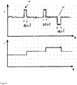
- FIG. 3 shows two graphs, namely in the upper part of a curve of an ascertained by the acceleration sensor 22 Acceleration measured values of the inclination angle ⁇ of the suction pipe 18 and in the lower part a graph of a designated by the symbol P power of a suction fan of the respective vacuum cleaner 10.
- the intake pipe 18 is changed in its inclination ⁇ for the first time, such that the intake pipe 18 is steeper, at least in the short term (greater inclination ⁇ ). This is done later again and at the end of the presentation in FIG.
- the reference numeral 26 designates a situation in which the suction pipe 18 is kept shallower (smaller inclination ⁇ ). Such waveforms can be used to adjust or influence a blower power P of the respective suction fan, as in the lower part of the illustration in FIG FIG. 3 is shown. Thereafter, each time the inclination ⁇ of the suction pipe 18 is increased for a predetermined duration (here expressed as ⁇ t> T), the blower power P of the suction fan is increased, as can be seen from the two-stage rising graph of the blower power P. If finally according to the in FIG.
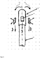
- FIG. 4 illustrates that with the acceleration sensor 22 not only a changed inclination ⁇ of the suction pipe 18, but also a rotation 50, 52 of the grip member 16 can be detected.
- FIG. 4 With a rotatability of the gripping element 16 or a rotatable portion of the gripping element 16, a setting or influencing of a blower power P of the suction blower of the respective vacuum cleaner 10 is also possible by a rotary movement.
- FIG. 5 explained (in a similar representation as FIG. 3 ) the effect of a realizable with a rotatable handle member 16 operating concept.
- FIG. 5 shows FIG. 5 in the upper area, a graph of a rotational angle, determined on the basis of the acceleration measured values obtained by the acceleration sensor 22, of the grip element 16, which is designated here symbolically by the symbol ⁇ .
- a progression of the blower power of the suction blower designated by the formula P is shown over the same time base.
- the grip element 16 is for the first time noticeably rotated, for example, to the right, and this rotation position lasts at least for a predetermined duration (.DELTA.t> T), so that the adjustment of the blower power P can take place with the passage of the predetermined duration
- a reduction in the blower power P which can be seen from the descending stage of the graph for the blower power P.
- Such a reduction of the blower power P takes place at a later time by a further right turn 52 of the grip element 16 again and at the conclusion of the illustration in FIG FIG. 5 is denoted by the reference numeral 26, a situation in which the grip member 16 undergoes a left turn 50.
- this rotational position stops for more than a predetermined period of time T, so that at the end of the period influencing the fan power P takes place.
- FIG. 6 shows the representation in FIG. 6 in that likewise a continuous adjustment of the blower power P, for example as a function of the inclination ⁇ of the suction pipe 18 (or of the rotation 50, 52 of the gripping element 16), can take place.
- a situation is shown in which the suction tube 18 is initially in a medium inclination 35. Thereafter, the suction tube 18 is kept flatter (the inclination angle ⁇ thus decreases).
- FIG. 6 shows in the lower part of the correlated with the reduced inclination ⁇ of the suction pipe 18 increased blower power P.
- the suction pipe 18 is steeper steered at the end of the period considered and the blower power P is withdrawn, because at a steeper position and a correspondingly increased inclination of the suction pipe 18 results in a less favorable lever with respect to the movement of the suction nozzle 20, so that movement of the Suction nozzle 20 with a comparable use of force is only possible if the blower power P is reduced. Accordingly, a steeper orientation of the suction pipe 18 is interpreted as a control action for the reduction of the blower power P.
- FIG. 7 shows an adjustment of the blower power P of the suction fan according to a forward movement 46 (FIG. FIG. 2 . FIG. 8 ) and backward movement 48 ( FIG. 2 . FIG. 8 ) of the suction nozzle 20 during the suction process.
- This is with two graphs as with the previous ones Figures 3 . 5 and 6 in the upper part of the illustration, an inclination ⁇ of the suction pipe 18 and in the lower part of the illustration, a blower power P of the suction fan shown.
- the graphs are divided into three sections, namely first, second and third sections 30, 32, 34.
- the inclination ⁇ of the suction pipe 18 begins above a mean inclination 35 and decreases continuously to a value below an average inclination 35 from. This is characteristic of a forward movement 46 of a suction nozzle 20 by means of a suction tube 18.
- the inclination ⁇ of the suction tube 18 increases from a value below the mean inclination 35 to a value above the mean inclination 35, as for a backward movement 48 ( FIG. 2 . FIG. 8 ) is characteristic, and in the third section 34, the value of the inclination ⁇ of the suction pipe 18 decreases again similar to the first section 30.
- the three sections 30, 32, 34 thus represent the change in the inclination ⁇ of the suction pipe 18 in a forward movement 46 (first Section 30), a subsequent backward movement 48 (second section 32) and a
- the inclination ⁇ suction pipe 18 can be determined by an arrangement of the acceleration sensor 22 in or on the handle member 16 as well as by an arrangement of the acceleration sensor 28 in or on the connecting piece 21 of the suction nozzle 20.
- the arrangement of the acceleration sensor 28 in the suction nozzle 20 is not shown in detail. However, the same applies here as for the acceleration sensor 22. Also for the acceleration sensor 28, measured values for the gravitational acceleration acting on the acceleration sensor 28 can be determined in three independent spatial directions. The inclination of the suction nozzle or the inclination of the connecting piece 21 can be determined via the gravitational acceleration acting downwards. Of particular importance for the arrangement of the acceleration sensor 28 in the suction nozzle 20, however, is the sensing of the accelerations of the suction nozzle 20 in forward movement 46 (FIG. FIG. 2 . FIG. 8 ) and opposite backward motion 48 (FIG. FIG. 2 . FIG. 8 ) during the suction process.
- Forward motion 46 and reverse motion 48 (FIG. FIG. 2 . FIG. 8 ) of the suction nozzle during the suction process can also be detected directly by arranging the acceleration sensor 28 in the suction nozzle 20. It is also conceivable, however, to combine a plurality of acceleration sensors into suction nozzle and grip element in order to make the respective suction situation more clearly recognizable.
- FIG. 7 illustrates, in its entirety, that with the forward motion 46 normally included in a suction process, 46 (FIG. FIG. 2 . FIG. 8 ) and backward movements 48 ( FIG. 2 . FIG. 8 ) of the suction nozzle 20 may be associated with adjustments or adjustments of the blower power P of the suction fan of the respective vacuum cleaner 10.
- the lower part of the illustration in FIG. 7 shows two variants.
- the respective resulting blower power P can be adjusted in accordance with the inclination ⁇ of the suction pipe 18 during a forward movement 46 (FIG. FIG. 2 . FIG. 8 ) or backward movement 48 (FIG. FIG. 2 .
- FIG. 7 illustrates, in its entirety, that with the forward motion 46 normally included in a suction process, 46 (FIG. FIG. 2 . FIG. 8 ) and backward movements 48 ( FIG. 2 . FIG. 8 ) of the suction nozzle 20 may be associated with adjustments or adjustments of the blower power P of the suction fan of the respective vacuum
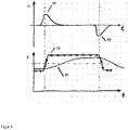
- FIG. 8 shows that during a suction process and the forward movement 46 and backward movements 48 of the suction nozzle 20 normally associated therewith, adjustments or adjustments of the blower output P of the suction blower of the respective vacuum cleaner 10 may occur.
- the lower part of the illustration in FIG. 8 shows two variants.
- the respective resulting blower power P corresponding to the acceleration a x of the suction nozzle 20 can be set to fixed blower power values at a forward movement 46 and backward movement 48 of the suction nozzle 20, as shown in the fixed power graph 36.
- the switching between an upper fixed power value and a lower fixed power value takes place, for example, at sufficiently significant inflection points of the course of the acceleration a x of the suction nozzle 20.
- an adjustment or influencing of the blower output P of the respective suction blower can also be carried out for other usage scenarios.
- the suction tube 18 is lowered almost horizontally and at the same time the handle element 16 is rotated 90 degrees, so that the floor nozzle acting as a suction nozzle 20 can lie flat due to their hinged connection to the suction tube, it can be assumed that under a low piece of furniture, for example, a sofa, to be sucked.
- the previous blower power P of the normal operation could be maintained.
- the suction tube 18 are held without rotation 50, 52 of the handle member 16 in the horizontal or even steep upward, so it is assumed that curtains or ceilings are sucked. In this case, the blower power P could be automatically reduced significantly.
- an interruption or termination of a suction process can be detected, because at such an interruption or termination of the suction, the suction pipe 18 is often brought for a long time in a vertical position, ie a so-called parking position, so that upon detection of such a tendency ⁇ of the suction pipe 18, the suction fan could be completely switched off.
- a separate switch to detect the parking position as previously required for deactivation of the suction fan when the parking position, could then be omitted.
- a dropping of the suction pipe 18 next to the vacuum cleaner 10 can be detected and in the absence of further movements of the suction pipe 18 or the handle member 16, the suction fan can be switched off. The reconnection of the suction fan can then be done automatically as soon as movements of the grip element 16 or a suction angle for the usual inclination angle of the suction pipe 18 are detected.
- FIG. 9 shows a schematically simplified block diagram for clarifying the processes when setting or influencing a blower power P of a suction blower 40 enclosed by the respective vacuum cleaner 10.
- the acceleration sensor 22 delivers one or more acceleration measurement values which are processed by a logic unit.
- the logic unit 42 handles the processing of the or each acceleration measurement value provided by the acceleration sensor 22 in accordance with predetermined logical operations.
- the setting of the fan power P of the suction fan 40 then takes place as a function of the result of these logic operations.
- FIG. 9 In this respect, schematically shows a plurality of logic networks 44 for implementing such logic operations, to which each or each acceleration measurement value supplied by the acceleration sensor 22 is supplied.
- Each logic network 44 has logic operations with which a particular usage situation of the vacuum cleaner 10 or a specific operating action on the vacuum cleaner 10 can be seen. For example, in a continuous adjustment of the blower power P of the suction fan 40 in response to an inclination ⁇ of the suction pipe 18, a first logic network 44 due to the respectively determined inclination angle ⁇ of the suction pipe 18 determine a suitable blower power P. Another logic network 44 could recognize sudden changes in the inclination ⁇ of the intake manifold 18 and monitor whether a sudden change in inclination ⁇ of the intake manifold 18 longer than a predetermined period (see. FIG. 3 ) persists.
- the logic unit 42 can respond to either use scenario according to either a continuous or a spike adjustment of the blower power P.
- the logic unit 42 further, possibly also individually activatable or deactivatable logic networks 44 include the other with reference to the other Figures 4-8
- a linking or mutual interlocking of the individual signals respectively generated by the logic networks 44 can take place in order to prevent contradictory activation of the suction blower 40 with a respective setpoint value for the blower output P given a simultaneous activity of a plurality of logic networks 44.
- Vacuum cleaners 10 are provided with a device for setting a fan power of a suction fan 40 encompassed by the vacuum cleaner 10, an acceleration sensor 22 functioning as a device for setting a fan power a method for operating such a vacuum cleaner, wherein detected by the acceleration sensor 22, at least one acceleration reading and depending on the fan power of the suction fan 40 is changed.
Landscapes
- Engineering & Computer Science (AREA)
- Mechanical Engineering (AREA)
- Electric Vacuum Cleaner (AREA)
Claims (11)
- Aspirateur (10) chez lequel un capteur d'accélération (22) fonctionne en tant que dispositif de réglage de la puissance d'aspiration d'un ventilateur d'aspiration (40) compris dans l'aspirateur (10), lequel capteur d'accélération est fixé sur ou dans un élément de poignée (16) de l'aspirateur (10), caractérisé en ce qu'une rotation (50, 52) de l'élément de poignée (16) peut être détectée avec le capteur d'accélération (22).
- Aspirateur (10) selon la revendication 1, dans lequel un capteur d'accélération (28) est fixé sur une buse d'aspiration (20) ou est intégré dans une telle buse d'aspiration (20).
- Aspirateur (10) selon l'une des revendications précédentes, dans lequel un mouvement vers l'avant ou vers l'arrière (46, 48) d'une buse d'aspiration (20) de l'aspirateur (10) peut être détecté avec le capteur d'accélération (22, 28).
- Aspirateur (10) selon la revendication 1 ou la revendication 2, dans lequel une inclinaison d'un tuyau d'aspiration (18) de l'aspirateur (10) se trouvant en aval par rapport à l'élément de poignée (16) ou une inclinaison de l'aspirateur (10) peut être détectée avec le capteur d'accélération (22).
- Aspirateur (10) selon l'une des revendications précédentes, doté d'une unité logique (42) pour l'exploitation d'une valeur de mesure d'accélération délivrée par le capteur d'accélération (22, 28) conformément à des couplages logiques prédéfinis et pour le réglage de la puissance d'aspiration du ventilateur d'aspiration (40) en fonction du résultat des couplages logiques.
- Aspirateur (10) selon la revendication 5, dans lequel divers scénarios d'utilisation de l'aspirateur (10) sont prévus sous la forme d'une multiplicité de couplages logiques et dans lequel la puissance d'aspiration est réglable en fonction du résultat des couplages logiques et en fonction du scénario d'utilisation respectivement reconnu par ceux-ci.
- Procédé de fonctionnement d'un aspirateur (10) selon l'une des revendications précédentes, dans lequel au moins une valeur de mesure d'accélération d'une composante de l'aspirateur (10) est détectée avec le capteur d'accélération (22), et est évaluée en tant qu'indice pour une rotation (50, 52) d'un élément de poignée (16) de l'aspirateur (10) et dans lequel, lors d'une rotation (50, 52) de l'élément de poignée (16), augmente la puissance d'aspiration dans un premier sens et diminue la puissance d'aspiration dans un second sens opposé lors d'une rotation (50, 52) de l'élément de poignée (16).
- Procédé selon la revendication 7, dans lequel la puissance d'aspiration est modifiée en continu en fonction d'une valeur de mesure d'accélération détectée avec le capteur d'accélération (22, 28).
- Procédé selon la revendication 7, dans lequel la puissance d'aspiration est modifiée de manière discrète d'une quantité prédéfinie ou prédéfinissable lorsqu'une valeur de mesure d'accélération détectée avec le capteur d'accélération (22, 28) dépasse ou est inférieure à une valeur de seuil prédéfinie ou prédéfinissable.
- Procédé selon l'une des revendications 7 à 9, dans lequel une valeur de mesure d'accélération détectée avec le capteur d'accélération (22, 28) est évaluée en tant qu'indice pour un mouvement vers l'avant ou vers l'arrière (46, 48) d'une buse d'aspiration (20) de l'aspirateur (10) et dans lequel la puissance d'aspiration est augmentée lors d'un mouvement vers l'avant (46) et la puissance d'aspiration est diminuée lors d'un mouvement vers l'arrière (48).
- Procédé selon l'une des revendications 7 à 10, dans lequel une valeur de mesure d'accélération détectée avec le capteur d'accélération (22) est évaluée en tant qu'indice pour une inclinaison d'un tuyau d'aspiration (18) de l'aspirateur (10) et dans lequel la puissance d'aspiration est diminuée pour une position fortement inclinée du tuyau d'aspiration (18) et la puissance d'aspiration est augmentée pour une position plane du tuyau d'aspiration (18).
Applications Claiming Priority (1)
| Application Number | Priority Date | Filing Date | Title |
|---|---|---|---|
| DE102012105845.8A DE102012105845A1 (de) | 2012-07-02 | 2012-07-02 | Staubsauger mit einer Vorrichtung zur Einstellung einer Gebläseleistung und Verfahren zum Betrieb eines solchen Staubsaugers |
Publications (3)
| Publication Number | Publication Date |
|---|---|
| EP2682034A2 EP2682034A2 (fr) | 2014-01-08 |
| EP2682034A3 EP2682034A3 (fr) | 2017-12-27 |
| EP2682034B1 true EP2682034B1 (fr) | 2019-02-27 |
Family
ID=48795538
Family Applications (1)
| Application Number | Title | Priority Date | Filing Date |
|---|---|---|---|
| EP13401061.0A Active EP2682034B1 (fr) | 2012-07-02 | 2013-06-26 | Aspirateur à poussière doté d'un dispositif de réglage d'une puissance de ventilateur et procédé de fonctionnement d'un tel aspirateur à poussière |
Country Status (2)
| Country | Link |
|---|---|
| EP (1) | EP2682034B1 (fr) |
| DE (1) | DE102012105845A1 (fr) |
Cited By (1)
| Publication number | Priority date | Publication date | Assignee | Title |
|---|---|---|---|---|
| EP4464218A4 (fr) * | 2022-01-21 | 2025-03-19 | LG Electronics Inc. | Aspirateur et son procédé de commande |
Families Citing this family (18)
| Publication number | Priority date | Publication date | Assignee | Title |
|---|---|---|---|---|
| DE102015106885A1 (de) * | 2015-05-04 | 2016-11-10 | Miele & Cie. Kg | Staubsauger und Verfahren zum Steuern eines Saugbetriebs eines Staubsaugers |
| DE102015108464A1 (de) * | 2015-05-28 | 2016-12-01 | Vorwerk & Co. Interholding Gmbh | Verfahren zum Betrieb eines elektromotorisch angetriebenen Gerätes |
| KR101842463B1 (ko) * | 2016-07-08 | 2018-03-27 | 엘지전자 주식회사 | 진공 청소기 및 청소기의 핸들 |
| DE102016120439A1 (de) * | 2016-10-26 | 2018-04-26 | Miele & Cie. Kg | Verfahren und Steuergerät zum Regeln einer Leistung eines Gebläses eines Staubsaugers und Staubsauger mit einem Steuergerät |
| FR3068839B1 (fr) * | 2017-07-07 | 2019-07-26 | Seb S.A. | Procede de regulation de la puissance d’aspiration d’un aspirateur balai sans fil |
| CN114190845B (zh) | 2017-12-18 | 2023-03-28 | 创科地板护理技术有限公司 | 具有无触发流体分配机构的表面清洁设备 |
| US11382477B2 (en) | 2017-12-18 | 2022-07-12 | Techtronic Floor Care Technology Limited | Surface cleaning device with automated control |
| EP3569124B1 (fr) * | 2018-05-18 | 2021-08-18 | Miele & Cie. KG | Appareil de nettoyage |
| DE102020200483A1 (de) | 2020-01-16 | 2021-07-22 | Robert Bosch Gesellschaft mit beschränkter Haftung | Verfahren zur Steuerung eines Sauggeräts |
| GB2596858B (en) | 2020-07-10 | 2023-01-04 | Dyson Technology Ltd | Vacuum cleaner |
| GB2596861B (en) * | 2020-07-10 | 2023-01-04 | Dyson Technology Ltd | Vacuum cleaner |
| GB2596857B (en) | 2020-07-10 | 2023-01-04 | Dyson Technology Ltd | Vacuum cleaner |
| GB2596855B (en) | 2020-07-10 | 2023-01-04 | Dyson Technology Ltd | Vacuum cleaner |
| GB2596854B (en) | 2020-07-10 | 2023-03-29 | Dyson Technology Ltd | Vacuum cleaner |
| ES2910899A1 (es) * | 2020-11-13 | 2022-05-13 | Cecotec Res And Development Sl | Aparato electronico de limpieza y/o desinfeccion con medios de medicion inercial (imu) y metodo para operarlo |
| CN114652230A (zh) * | 2020-12-22 | 2022-06-24 | 美智纵横科技有限责任公司 | 清洁设备及其控制方法、设备和计算机程序产品 |
| CN113643954A (zh) * | 2021-07-07 | 2021-11-12 | 深圳拓邦股份有限公司 | 等离子体发生控制方法、装置及清洁仪 |
| DE202021002931U1 (de) | 2021-09-11 | 2021-10-01 | Matthias Jünemann | Equilateraler Flächenreiniger |
Family Cites Families (11)
| Publication number | Priority date | Publication date | Assignee | Title |
|---|---|---|---|---|
| DE4427639A1 (de) * | 1993-12-04 | 1995-06-08 | Vorwerk Co Interholding | Mittels eines Elektromotors betriebener Staubsauger |
| US5748853A (en) * | 1994-07-13 | 1998-05-05 | Moulinex S.A. | Vacuum cleaner with fuzzy logic control unit |
| DE19602723C2 (de) * | 1996-01-26 | 2001-04-19 | Gerhard Kurz | Vorrichtung zum Betrieb eines Staubsaugers |
| JPH11313789A (ja) * | 1998-05-06 | 1999-11-16 | Matsushita Electric Ind Co Ltd | 電気掃除機の制御装置 |
| JP2003319894A (ja) * | 2002-04-30 | 2003-11-11 | Toshiba Tec Corp | 吸込口体と電気掃除機 |
| DE10338874A1 (de) * | 2002-09-07 | 2004-03-18 | Vorwerk & Co. Interholding Gmbh | Staubsauger mit einem Elektromotor und einem Vorsatzgerät |
| US8438693B2 (en) * | 2006-09-11 | 2013-05-14 | Panasonic Corporation | Electric cleaner |
| JP4813433B2 (ja) * | 2007-08-29 | 2011-11-09 | シャープ株式会社 | 電気掃除機 |
| JP2011206351A (ja) * | 2010-03-30 | 2011-10-20 | Panasonic Corp | 電気掃除機 |
| JP5603951B2 (ja) * | 2010-12-06 | 2014-10-08 | シャープ株式会社 | 電気掃除機 |
| JP2012148010A (ja) * | 2011-01-21 | 2012-08-09 | Panasonic Corp | 電気掃除機 |
-
2012
- 2012-07-02 DE DE102012105845.8A patent/DE102012105845A1/de not_active Withdrawn
-
2013
- 2013-06-26 EP EP13401061.0A patent/EP2682034B1/fr active Active
Non-Patent Citations (1)
| Title |
|---|
| None * |
Cited By (1)
| Publication number | Priority date | Publication date | Assignee | Title |
|---|---|---|---|---|
| EP4464218A4 (fr) * | 2022-01-21 | 2025-03-19 | LG Electronics Inc. | Aspirateur et son procédé de commande |
Also Published As
| Publication number | Publication date |
|---|---|
| EP2682034A2 (fr) | 2014-01-08 |
| EP2682034A3 (fr) | 2017-12-27 |
| DE102012105845A1 (de) | 2014-01-02 |
Similar Documents
| Publication | Publication Date | Title |
|---|---|---|
| EP2682034A2 (fr) | Aspirateur à poussière doté d'un dispositif de réglage d'une puissance de ventilateur et procédé de fonctionnement d'un tel aspirateur à poussière | |
| EP2679086B1 (fr) | Machine de récolte automotrice dotée d'un tête de coupe réglable en hauteur | |
| EP2219505B1 (fr) | Dispositif de régulation de débit volumique d'air et de force de poussée | |
| EP2222215B1 (fr) | Dispositif de commande ou de régulation de la puissance moteur d'un aspirateur | |
| DE10207360B4 (de) | Sitz | |
| EP3162266B1 (fr) | Appareil de nettoyage et procédé pour utiliser l'appareil de nettoyage | |
| DE102009020842B4 (de) | System zum Steuern der Geschwindigkeit eines Elektromotors in einem Kraftfahrzeug | |
| EP2377445B1 (fr) | Aspirateur avec un dispositif de régulation du ventilateur | |
| EP2910097A1 (fr) | Dispositif de commande amortissant les vibrations d'un actionneur d'une machine de travail agricole | |
| EP2583586A1 (fr) | Dispositif de détection de collisions et procédé associé | |
| EP2245974A2 (fr) | Procédé d'opération d'un appareil adaptable pour un aspirateur et appareil adaptable correspondant | |
| EP4030888A1 (fr) | Unité de coupe comportant des capteurs pour la régulation de la hauteur | |
| DE102012212846A1 (de) | Ballenpresse | |
| DE102015108464A1 (de) | Verfahren zum Betrieb eines elektromotorisch angetriebenen Gerätes | |
| DE102016108579A1 (de) | Näherungssensorbaugruppe mit verschachtelter elektrodenanordnung | |
| DE102020110742A1 (de) | Einstellradhöhensteuerung für eine Erntegutbergungseinrichtung | |
| EP1790252B1 (fr) | Système de commande pour l'ouverture de tiroirs sans poignée, en appuyant sur la face frontale sans que la course d'actionnement ne soit augmentée | |
| EP1064162A1 (fr) | Procede et dispositif permettant de faire fonctionner une commande de reglage dans un vehicule | |
| DE102016217078A1 (de) | Verfahren zum Steuern einer Gehhilfe, Steuereinrichtung für eine Gehhilfe, Gehhilfe | |
| EP2691003B1 (fr) | Procédé pour faire fonctionner un aspirateur en fonction de la pression d'aspiration | |
| EP4125523B1 (fr) | Nettoyage des filtres en fonction de la demande | |
| EP3108785A1 (fr) | Aspirateur et procede destine au fonctionnement d'un aspirateur | |
| EP2842471A1 (fr) | Aspirateur doté d'une commande destinée à régler la puissance de la soufflante | |
| EP2781179B1 (fr) | Procédé de réglage de la puissance d'un ventilateur d'aspirateur, dispositif de régulation pour la mise en oeuvre du procédé et aspirateur doté d'un tel dispositif de régulation | |
| DE102007020801A1 (de) | In der Höhe einstellbare Landbearbeitungseinrichtung |
Legal Events
| Date | Code | Title | Description |
|---|---|---|---|
| PUAI | Public reference made under article 153(3) epc to a published international application that has entered the european phase |
Free format text: ORIGINAL CODE: 0009012 |
|
| AK | Designated contracting states |
Kind code of ref document: A2 Designated state(s): AL AT BE BG CH CY CZ DE DK EE ES FI FR GB GR HR HU IE IS IT LI LT LU LV MC MK MT NL NO PL PT RO RS SE SI SK SM TR |
|
| AX | Request for extension of the european patent |
Extension state: BA ME |
|
| PUAL | Search report despatched |
Free format text: ORIGINAL CODE: 0009013 |
|
| AK | Designated contracting states |
Kind code of ref document: A3 Designated state(s): AL AT BE BG CH CY CZ DE DK EE ES FI FR GB GR HR HU IE IS IT LI LT LU LV MC MK MT NL NO PL PT RO RS SE SI SK SM TR |
|
| AX | Request for extension of the european patent |
Extension state: BA ME |
|
| RIC1 | Information provided on ipc code assigned before grant |
Ipc: A47L 9/28 20060101AFI20171117BHEP |
|
| STAA | Information on the status of an ep patent application or granted ep patent |
Free format text: STATUS: REQUEST FOR EXAMINATION WAS MADE |
|
| 17P | Request for examination filed |
Effective date: 20180116 |
|
| RBV | Designated contracting states (corrected) |
Designated state(s): AL AT BE BG CH CY CZ DE DK EE ES FI FR GB GR HR HU IE IS IT LI LT LU LV MC MK MT NL NO PL PT RO RS SE SI SK SM TR |
|
| GRAJ | Information related to disapproval of communication of intention to grant by the applicant or resumption of examination proceedings by the epo deleted |
Free format text: ORIGINAL CODE: EPIDOSDIGR1 |
|
| STAA | Information on the status of an ep patent application or granted ep patent |
Free format text: STATUS: GRANT OF PATENT IS INTENDED |
|
| GRAP | Despatch of communication of intention to grant a patent |
Free format text: ORIGINAL CODE: EPIDOSNIGR1 |
|
| INTG | Intention to grant announced |
Effective date: 20181025 |
|
| GRAS | Grant fee paid |
Free format text: ORIGINAL CODE: EPIDOSNIGR3 |
|
| GRAA | (expected) grant |
Free format text: ORIGINAL CODE: 0009210 |
|
| STAA | Information on the status of an ep patent application or granted ep patent |
Free format text: STATUS: THE PATENT HAS BEEN GRANTED |
|
| REG | Reference to a national code |
Ref country code: DE Ref legal event code: R084 Ref document number: 502013012286 Country of ref document: DE |
|
| AK | Designated contracting states |
Kind code of ref document: B1 Designated state(s): AL AT BE BG CH CY CZ DE DK EE ES FI FR GB GR HR HU IE IS IT LI LT LU LV MC MK MT NL NO PL PT RO RS SE SI SK SM TR |
|
| REG | Reference to a national code |
Ref country code: GB Ref legal event code: FG4D Free format text: NOT ENGLISH |
|
| REG | Reference to a national code |
Ref country code: CH Ref legal event code: EP |
|
| REG | Reference to a national code |
Ref country code: AT Ref legal event code: REF Ref document number: 1100147 Country of ref document: AT Kind code of ref document: T Effective date: 20190315 |
|
| REG | Reference to a national code |
Ref country code: IE Ref legal event code: FG4D Free format text: LANGUAGE OF EP DOCUMENT: GERMAN |
|
| REG | Reference to a national code |
Ref country code: DE Ref legal event code: R096 Ref document number: 502013012286 Country of ref document: DE |
|
| REG | Reference to a national code |
Ref country code: GB Ref legal event code: 746 Effective date: 20190312 |
|
| REG | Reference to a national code |
Ref country code: NL Ref legal event code: MP Effective date: 20190227 |
|
| REG | Reference to a national code |
Ref country code: LT Ref legal event code: MG4D |
|
| PG25 | Lapsed in a contracting state [announced via postgrant information from national office to epo] |
Ref country code: PT Free format text: LAPSE BECAUSE OF FAILURE TO SUBMIT A TRANSLATION OF THE DESCRIPTION OR TO PAY THE FEE WITHIN THE PRESCRIBED TIME-LIMIT Effective date: 20190627 Ref country code: LT Free format text: LAPSE BECAUSE OF FAILURE TO SUBMIT A TRANSLATION OF THE DESCRIPTION OR TO PAY THE FEE WITHIN THE PRESCRIBED TIME-LIMIT Effective date: 20190227 Ref country code: NO Free format text: LAPSE BECAUSE OF FAILURE TO SUBMIT A TRANSLATION OF THE DESCRIPTION OR TO PAY THE FEE WITHIN THE PRESCRIBED TIME-LIMIT Effective date: 20190527 Ref country code: NL Free format text: LAPSE BECAUSE OF FAILURE TO SUBMIT A TRANSLATION OF THE DESCRIPTION OR TO PAY THE FEE WITHIN THE PRESCRIBED TIME-LIMIT Effective date: 20190227 Ref country code: SE Free format text: LAPSE BECAUSE OF FAILURE TO SUBMIT A TRANSLATION OF THE DESCRIPTION OR TO PAY THE FEE WITHIN THE PRESCRIBED TIME-LIMIT Effective date: 20190227 Ref country code: FI Free format text: LAPSE BECAUSE OF FAILURE TO SUBMIT A TRANSLATION OF THE DESCRIPTION OR TO PAY THE FEE WITHIN THE PRESCRIBED TIME-LIMIT Effective date: 20190227 |
|
| PG25 | Lapsed in a contracting state [announced via postgrant information from national office to epo] |
Ref country code: GR Free format text: LAPSE BECAUSE OF FAILURE TO SUBMIT A TRANSLATION OF THE DESCRIPTION OR TO PAY THE FEE WITHIN THE PRESCRIBED TIME-LIMIT Effective date: 20190528 Ref country code: RS Free format text: LAPSE BECAUSE OF FAILURE TO SUBMIT A TRANSLATION OF THE DESCRIPTION OR TO PAY THE FEE WITHIN THE PRESCRIBED TIME-LIMIT Effective date: 20190227 Ref country code: BG Free format text: LAPSE BECAUSE OF FAILURE TO SUBMIT A TRANSLATION OF THE DESCRIPTION OR TO PAY THE FEE WITHIN THE PRESCRIBED TIME-LIMIT Effective date: 20190527 Ref country code: IS Free format text: LAPSE BECAUSE OF FAILURE TO SUBMIT A TRANSLATION OF THE DESCRIPTION OR TO PAY THE FEE WITHIN THE PRESCRIBED TIME-LIMIT Effective date: 20190627 Ref country code: LV Free format text: LAPSE BECAUSE OF FAILURE TO SUBMIT A TRANSLATION OF THE DESCRIPTION OR TO PAY THE FEE WITHIN THE PRESCRIBED TIME-LIMIT Effective date: 20190227 Ref country code: HR Free format text: LAPSE BECAUSE OF FAILURE TO SUBMIT A TRANSLATION OF THE DESCRIPTION OR TO PAY THE FEE WITHIN THE PRESCRIBED TIME-LIMIT Effective date: 20190227 |
|
| PG25 | Lapsed in a contracting state [announced via postgrant information from national office to epo] |
Ref country code: IT Free format text: LAPSE BECAUSE OF FAILURE TO SUBMIT A TRANSLATION OF THE DESCRIPTION OR TO PAY THE FEE WITHIN THE PRESCRIBED TIME-LIMIT Effective date: 20190227 Ref country code: SK Free format text: LAPSE BECAUSE OF FAILURE TO SUBMIT A TRANSLATION OF THE DESCRIPTION OR TO PAY THE FEE WITHIN THE PRESCRIBED TIME-LIMIT Effective date: 20190227 Ref country code: AL Free format text: LAPSE BECAUSE OF FAILURE TO SUBMIT A TRANSLATION OF THE DESCRIPTION OR TO PAY THE FEE WITHIN THE PRESCRIBED TIME-LIMIT Effective date: 20190227 Ref country code: ES Free format text: LAPSE BECAUSE OF FAILURE TO SUBMIT A TRANSLATION OF THE DESCRIPTION OR TO PAY THE FEE WITHIN THE PRESCRIBED TIME-LIMIT Effective date: 20190227 Ref country code: DK Free format text: LAPSE BECAUSE OF FAILURE TO SUBMIT A TRANSLATION OF THE DESCRIPTION OR TO PAY THE FEE WITHIN THE PRESCRIBED TIME-LIMIT Effective date: 20190227 Ref country code: CZ Free format text: LAPSE BECAUSE OF FAILURE TO SUBMIT A TRANSLATION OF THE DESCRIPTION OR TO PAY THE FEE WITHIN THE PRESCRIBED TIME-LIMIT Effective date: 20190227 Ref country code: EE Free format text: LAPSE BECAUSE OF FAILURE TO SUBMIT A TRANSLATION OF THE DESCRIPTION OR TO PAY THE FEE WITHIN THE PRESCRIBED TIME-LIMIT Effective date: 20190227 Ref country code: RO Free format text: LAPSE BECAUSE OF FAILURE TO SUBMIT A TRANSLATION OF THE DESCRIPTION OR TO PAY THE FEE WITHIN THE PRESCRIBED TIME-LIMIT Effective date: 20190227 |
|
| REG | Reference to a national code |
Ref country code: DE Ref legal event code: R097 Ref document number: 502013012286 Country of ref document: DE |
|
| PG25 | Lapsed in a contracting state [announced via postgrant information from national office to epo] |
Ref country code: SM Free format text: LAPSE BECAUSE OF FAILURE TO SUBMIT A TRANSLATION OF THE DESCRIPTION OR TO PAY THE FEE WITHIN THE PRESCRIBED TIME-LIMIT Effective date: 20190227 Ref country code: PL Free format text: LAPSE BECAUSE OF FAILURE TO SUBMIT A TRANSLATION OF THE DESCRIPTION OR TO PAY THE FEE WITHIN THE PRESCRIBED TIME-LIMIT Effective date: 20190227 |
|
| PLBE | No opposition filed within time limit |
Free format text: ORIGINAL CODE: 0009261 |
|
| STAA | Information on the status of an ep patent application or granted ep patent |
Free format text: STATUS: NO OPPOSITION FILED WITHIN TIME LIMIT |
|
| PG25 | Lapsed in a contracting state [announced via postgrant information from national office to epo] |
Ref country code: MC Free format text: LAPSE BECAUSE OF FAILURE TO SUBMIT A TRANSLATION OF THE DESCRIPTION OR TO PAY THE FEE WITHIN THE PRESCRIBED TIME-LIMIT Effective date: 20190227 |
|
| REG | Reference to a national code |
Ref country code: CH Ref legal event code: PL |
|
| 26N | No opposition filed |
Effective date: 20191128 |
|
| PG25 | Lapsed in a contracting state [announced via postgrant information from national office to epo] |
Ref country code: SI Free format text: LAPSE BECAUSE OF FAILURE TO SUBMIT A TRANSLATION OF THE DESCRIPTION OR TO PAY THE FEE WITHIN THE PRESCRIBED TIME-LIMIT Effective date: 20190227 |
|
| REG | Reference to a national code |
Ref country code: BE Ref legal event code: MM Effective date: 20190630 |
|
| PG25 | Lapsed in a contracting state [announced via postgrant information from national office to epo] |
Ref country code: TR Free format text: LAPSE BECAUSE OF FAILURE TO SUBMIT A TRANSLATION OF THE DESCRIPTION OR TO PAY THE FEE WITHIN THE PRESCRIBED TIME-LIMIT Effective date: 20190227 |
|
| PG25 | Lapsed in a contracting state [announced via postgrant information from national office to epo] |
Ref country code: IE Free format text: LAPSE BECAUSE OF NON-PAYMENT OF DUE FEES Effective date: 20190626 |
|
| PG25 | Lapsed in a contracting state [announced via postgrant information from national office to epo] |
Ref country code: LI Free format text: LAPSE BECAUSE OF NON-PAYMENT OF DUE FEES Effective date: 20190630 Ref country code: BE Free format text: LAPSE BECAUSE OF NON-PAYMENT OF DUE FEES Effective date: 20190630 Ref country code: CH Free format text: LAPSE BECAUSE OF NON-PAYMENT OF DUE FEES Effective date: 20190630 Ref country code: LU Free format text: LAPSE BECAUSE OF NON-PAYMENT OF DUE FEES Effective date: 20190626 |
|
| REG | Reference to a national code |
Ref country code: AT Ref legal event code: MM01 Ref document number: 1100147 Country of ref document: AT Kind code of ref document: T Effective date: 20190626 |
|
| PG25 | Lapsed in a contracting state [announced via postgrant information from national office to epo] |
Ref country code: AT Free format text: LAPSE BECAUSE OF NON-PAYMENT OF DUE FEES Effective date: 20190626 |
|
| PG25 | Lapsed in a contracting state [announced via postgrant information from national office to epo] |
Ref country code: CY Free format text: LAPSE BECAUSE OF FAILURE TO SUBMIT A TRANSLATION OF THE DESCRIPTION OR TO PAY THE FEE WITHIN THE PRESCRIBED TIME-LIMIT Effective date: 20190227 |
|
| PG25 | Lapsed in a contracting state [announced via postgrant information from national office to epo] |
Ref country code: HU Free format text: LAPSE BECAUSE OF FAILURE TO SUBMIT A TRANSLATION OF THE DESCRIPTION OR TO PAY THE FEE WITHIN THE PRESCRIBED TIME-LIMIT; INVALID AB INITIO Effective date: 20130626 Ref country code: MT Free format text: LAPSE BECAUSE OF FAILURE TO SUBMIT A TRANSLATION OF THE DESCRIPTION OR TO PAY THE FEE WITHIN THE PRESCRIBED TIME-LIMIT Effective date: 20190227 |
|
| PG25 | Lapsed in a contracting state [announced via postgrant information from national office to epo] |
Ref country code: MK Free format text: LAPSE BECAUSE OF FAILURE TO SUBMIT A TRANSLATION OF THE DESCRIPTION OR TO PAY THE FEE WITHIN THE PRESCRIBED TIME-LIMIT Effective date: 20190227 |
|
| P01 | Opt-out of the competence of the unified patent court (upc) registered |
Effective date: 20230529 |
|
| PGFP | Annual fee paid to national office [announced via postgrant information from national office to epo] |
Ref country code: DE Payment date: 20250630 Year of fee payment: 13 |
|
| PGFP | Annual fee paid to national office [announced via postgrant information from national office to epo] |
Ref country code: GB Payment date: 20250617 Year of fee payment: 13 |
|
| PGFP | Annual fee paid to national office [announced via postgrant information from national office to epo] |
Ref country code: FR Payment date: 20250624 Year of fee payment: 13 |