EP2682556A1 - Dispositif dýétanchéité pour une porte ou une fenêtre - Google Patents
Dispositif dýétanchéité pour une porte ou une fenêtre Download PDFInfo
- Publication number
- EP2682556A1 EP2682556A1 EP12174591.3A EP12174591A EP2682556A1 EP 2682556 A1 EP2682556 A1 EP 2682556A1 EP 12174591 A EP12174591 A EP 12174591A EP 2682556 A1 EP2682556 A1 EP 2682556A1
- Authority
- EP
- European Patent Office
- Prior art keywords
- lowering mechanism
- bolt
- seal
- sealing
- switching element
- Prior art date
- Legal status (The legal status is an assumption and is not a legal conclusion. Google has not performed a legal analysis and makes no representation as to the accuracy of the status listed.)
- Granted
Links
Images


Classifications
-
- E—FIXED CONSTRUCTIONS
- E06—DOORS, WINDOWS, SHUTTERS, OR ROLLER BLINDS IN GENERAL; LADDERS
- E06B—FIXED OR MOVABLE CLOSURES FOR OPENINGS IN BUILDINGS, VEHICLES, FENCES OR LIKE ENCLOSURES IN GENERAL, e.g. DOORS, WINDOWS, BLINDS, GATES
- E06B7/00—Special arrangements or measures in connection with doors or windows
- E06B7/16—Sealing arrangements on wings or parts co-operating with the wings
- E06B7/18—Sealing arrangements on wings or parts co-operating with the wings by means of movable edgings, e.g. draught sealings additionally used for bolting, e.g. by spring force or with operating lever
- E06B7/20—Sealing arrangements on wings or parts co-operating with the wings by means of movable edgings, e.g. draught sealings additionally used for bolting, e.g. by spring force or with operating lever automatically withdrawn when the wing is opened, e.g. by means of magnetic attraction, a pin or an inclined surface, especially for sills
- E06B7/215—Sealing arrangements on wings or parts co-operating with the wings by means of movable edgings, e.g. draught sealings additionally used for bolting, e.g. by spring force or with operating lever automatically withdrawn when the wing is opened, e.g. by means of magnetic attraction, a pin or an inclined surface, especially for sills with sealing strip being moved to a retracted position by elastic means, e.g. springs
Definitions
- the present invention relates to a sealing arrangement for a door or a window according to the preamble of patent claim 1, a lowering seal for a door or a window according to the preamble of claim 12 and a switching element for use with such a sealing arrangement or such Absenkdichtung.
- Door seals are commonly used in areas where light passages should be prevented and / or soundproofing should be ensured.
- Lowerable door seals usually consist essentially of a housing in the form of a downwardly open, U-shaped rail, a held in this housing and relative to this sliding sealing strip with a sealing element and a drive mechanism for lowering or lifting the sealing strip.
- the sealing strip automatically lowers when closing the door by a longitudinal force acting on an actuating rod or slider and sets the mechanical lowering mechanism in operation.
- Such door seals are made, for example EP 0 338 974 . DE 299 16 090 and EP 0 509 961 known. These door seals have proven themselves.
- US 5,964,060 shows a device for closing and sealing a door, wherein the sealing element is operated by a motor.
- An electronic keypad is used to activate the engine.
- EP 1 944 457 describes a seal assembly having a controllable actuator in the form of a reverse lift solenoid to turn the seal on and off.
- DE 297 20 978 U a device for locking doors in any pivoting angles.
- a folding lever actuates a cable, which acts on a lowering mechanism of a lowering seal.
- the folding lever is mounted in a front side of the door leaf. This device allows a lowering of the seal with the door open. When the door is closed, however, the seal is always lowered.
- DE 10 2007 047 179 discloses a device to lower the seal with the door open.
- a ram arranged in the door leaf presses on a U-shaped, closed-down rail of the door seal.
- DE 25 09 958 a magnetic seal in which the force field of the magnet is switched on and off to minimize wear of the sealing element.
- EP 0 334 307 Attempts to minimize wear by a solenoid is energized only when closing the door and only then a sunk in the ground under the door seal is raised by a lifting device in a sealing position.
- the sealing element is raised or lowered with the door closed. With the door open, this is Sealing element preferably always raised.
- the switching element can be operated electronically or mechanically, in particular manually, depending on the embodiment.
- the inventive sealing arrangement can thus be formed purely mechanically. Preferably, no magnets are present. This reduces the costs and the susceptibility to interference. It is also easy to use.
- the lowering mechanism is preferably part of the lowering seal, wherein the actuating element may be arranged for automatic detachment in the lowering seal, in the door frame or in another suitable part of the door.
- the switching element has a driver which transmits the movement of the first part to the second part.
- a driver is a part that also moves another part when moving. The driver is moved in this case preferably from the first part.
- the switching element acts as a jumper, it preferably fills an engagement opening between the first and second parts with approximately positive engagement.
- the switching element has a bolt which bridges a distance between the first and second part when the automatic lowering mechanism is switched on.
- This bolt is preferably used as a driver or jumper.
- the bolt may be fixed in the door or window sash, like a can-bolt bolt or a drive bolt, offset from the vertical end face of the door or window sash on which the lowering mechanism is deployed. This side is usually the hinged or hinge side of the door or window sash.
- the bolt has at its lower end at least one downwardly projecting lateral nose, wherein the bolt is preferably fork-shaped at this lower end, and wherein the bolt engages with the automatic lowering mechanism with this lower end a tapered portion of the first or second part.
- the bolt transmits the movement of the first part to the second part, wherein an approximately positive connection is created, which ensures a secure transmission of motion without loss of power.
- the shape, in particular the width of the bolt in this area is dimensioned so that the distance between a stop surface of the second part and the end of the first part is almost completely filled by the bolt.
- the bolt is raised and lowered perpendicular to a longitudinal direction of the lowering seal to turn on and off the automatic lowering mechanism.
- This allows the use of a lever or slide assembly for raising and lowering the bolt, as it is also used for graspriegelstangen and Kantriegelbolzen.
- the switching element has a hand-operated lever or a displacement element in order to raise and lower the driver or the bolt.
- automatic mechanical devices as well as magnetic, electronic or electromagnetic devices can also be used for this purpose.
- the switching element preferably penetrates a housing of the lowering seal to contact the first and / or the second part.
- the housing preferably has a passage opening.
- a trigger for the automatic movement of the Absenkdichtung can use the known triggers.
- it is a slider which is displaceable in a longitudinal direction of the lowering seal.
- the slider preferably forms the first and the second part.
- the slider is preferably on one side of the door and is pressed in closing the door, so as to activate the lowering mechanism. It can also be present at both ends of the seal slide.
- a slider can also be activated by lateral displacement, as for example in EP 2 085 559 is disclosed.
- the slider can also be arranged recessed in the door leaf, wherein in the door frame, a protruding element is present to move the slider.
- the first part has a cavity in which the second part is held displaceably spring-loaded, wherein the second part protrudes from the first part.
- the switching element engages with the automatic lowering mechanism in this projecting area.
- the projecting portion of the second part has at least one stop surface for the switching element, so that movement of the switching element in a longitudinal direction of the lowering seal is transferable to the second part; i.e. the switching element can act as a driver.
- the switching element can act as a driver.
- This embodiment has the advantage that in existing Absenkdichtache only the slide must be replaced and possibly an access to the slide must be created. A conversion of existing Absenkdichtitch in inventive Absenkdichtitch can thus be carried out easily and inexpensively.
- the first part is a hollow cylindrical pin and the second part is a cylinder pin engaging in this hollow cylinder, wherein the second part has at least two different outside diameters.
- the slider is thus stable. He is also easy to produce.
- the two parts can also be reversed, i. the first part intervenes in the second part.
- the switching element for use in an above-mentioned sealing arrangement or for use with an above lowering seal on a liftable and lowerable bolt, wherein the bolt has at its free lower end at least one downwardly projecting side nose, said Bolt is preferably fork-shaped at this lower end.
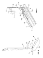
- the lowering seal D is essentially an automatically lowerable seal of known type.
- it has a seal housing 4 with a downwardly U-shaped open cross section.
- the seal housing 4 comprises two mutually parallel side walls 42 and the side walls 42 interconnecting web 40.
- In the housing 4 is a relative to the housing 4 liftable and lowerable sealing strip 5, 6 attached.
- the sealing strip usually has a carrier profile rail 6 and a sealing element attached thereto, a sealing profile 5.
- the housing 4 and the support rail 6 are preferably made of aluminum.
- the sealing profile 5 is preferably made of rubber or an elastomeric plastic, preferably made of silicone.
- the sealing profile 5 may be formed in one or more pieces. From the prior art, the most varied forms are known which can be used.
- a bolt 3 is lowered and raised.
- an actuating lever 20 is present, which is accessible from the outside of the rail 1 and can be pivoted from an upper to a lower position.
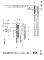
- the actuating mechanism of the bolt 3 is in FIG. 3 good to see.
- the reference numeral 25 denotes a pivot axis 25 of the lever 20.
- a push rod 23 is fixed to the lever 20.
- the push rod 23 slides along a guide rivet 26.
- the push rod 23 merges into an actuating rod 21, which extends approximately parallel to the longitudinal direction of the rail 1 and is angled at its lower end.
- the lever may also be a slider or other means to operate the bolt 3.
- the bolt 3 penetrates the housing 4, as in FIG. 2 is shown.
- the housing 4 has a through opening 41 in the web 40. Below this passage opening 41 of the inventive slider 7, as shown in FIG. 4 is shown.
- the slide 7 is, see FIGS. 4 and 6 , formed in several parts. It has a first part 70, which projects the housing 4 as an actuating button of the lowering mechanism. This first part 70 is formed as a hollow cylinder, wherein it is formed closed to its projecting free end. A second part 72 is spring loaded in this first part 70. The second part 72 is preferably formed in one piece. The first and second parts 70, 72 are preferably made of metal or a plastic.
- a transmission rod 73 is attached at the rear end of the main body 720. Preferably, it is screwed into a cavity of the base body 720.
- first part 70 By turning the housing 4 projecting first part 70 thus allows the distance of the first and second part relative to the transmission rod 73 and thus set the supernatant, i. the length of a protruding from the housing 4 portion of the slider 7.
- the first part has a screw slot 74 for this purpose.
- the transmission rod 73 is connected to a leaf spring 9 of the lowering mechanism and transmits the external force acting on the slider 7 to the leaf spring 9.
- the bolt 3 is lowered. It now engages in the engagement opening 8 and surrounds the taper 722. Preferably, it bears against a stop face 723 of the base body 720.
- the transition of the taper 722 to the base 720 is preferably for this purpose designed as a vertical step.
- the lower end of the bolt 3 bridges the distance between the base body 720 and the first part 70 completely or only with little play.
- the slide 7 is back to the housing 4 and the sealing strip 5, 6 is raised.
- the slider 7 is pressed again, preferably because the door is closed.
- the pin 3 can be pivoted thanks to the push rod 23 by a small angular range and can follow the movement of the first part 70 so.
- the bolt 3 acts as a driver or as a jumper. Preferably, it fills the engagement opening 8 with its fork approximately positively. Thanks to the lowered pin 3 and thus the second part 72 and the transmission rod 23 is moved and the leaf springs 9 are tensioned.
- the sealing strip 5, 6 is lowered.
- the inventive sealing arrangement thus enables by simple mechanical means on and off the automatic lowering mechanism.
Landscapes
- Engineering & Computer Science (AREA)
- Civil Engineering (AREA)
- Structural Engineering (AREA)
- Specific Sealing Or Ventilating Devices For Doors And Windows (AREA)
Priority Applications (1)
| Application Number | Priority Date | Filing Date | Title |
|---|---|---|---|
| EP12174591.3A EP2682556B1 (fr) | 2012-07-02 | 2012-07-02 | Dispositif d'étanchéité pour une porte ou une fenêtre |
Applications Claiming Priority (1)
| Application Number | Priority Date | Filing Date | Title |
|---|---|---|---|
| EP12174591.3A EP2682556B1 (fr) | 2012-07-02 | 2012-07-02 | Dispositif d'étanchéité pour une porte ou une fenêtre |
Publications (2)
| Publication Number | Publication Date |
|---|---|
| EP2682556A1 true EP2682556A1 (fr) | 2014-01-08 |
| EP2682556B1 EP2682556B1 (fr) | 2017-06-07 |
Family
ID=46466190
Family Applications (1)
| Application Number | Title | Priority Date | Filing Date |
|---|---|---|---|
| EP12174591.3A Active EP2682556B1 (fr) | 2012-07-02 | 2012-07-02 | Dispositif d'étanchéité pour une porte ou une fenêtre |
Country Status (1)
| Country | Link |
|---|---|
| EP (1) | EP2682556B1 (fr) |
Cited By (1)
| Publication number | Priority date | Publication date | Assignee | Title |
|---|---|---|---|---|
| US20220268094A1 (en) * | 2021-02-24 | 2022-08-25 | Baron Carleton | E-auto door bottom |
Citations (14)
| Publication number | Priority date | Publication date | Assignee | Title |
|---|---|---|---|---|
| DE2509958A1 (de) | 1975-03-07 | 1976-09-23 | Wagenbrenner Helmut | Abdichtungsvorrichtung fuer fugen zwischen beweglichen bauteilen |
| DE3124106A1 (de) | 1981-06-19 | 1982-12-30 | Fa. F. Athmer, 5760 Arnsberg | "abdichtungsvorrichtung fuer tueren" |
| US4519165A (en) * | 1984-01-05 | 1985-05-28 | F. Athmer | Sealing device for the bottom of a door |
| EP0334307A2 (fr) | 1988-03-23 | 1989-09-27 | Weissschädel, Hedwig | Dispositif d'étanchéité pour portes |
| EP0338974A2 (fr) | 1988-04-19 | 1989-10-25 | " Planet" Matthias Jaggi | Dispositif d'étanchéité pour portes sans seuil |
| EP0509961A1 (fr) | 1991-04-17 | 1992-10-21 | Planet MJT AG | Dispositif d'étanchéité, particulièrement pour battants de portes |
| DE19516530A1 (de) | 1994-06-01 | 1995-12-07 | Matthias Jaggi | Dichtungsvorrichtung, insbesondere für Türflügel |
| DE29720978U1 (de) | 1997-11-26 | 1998-03-12 | Ernst Keller GmbH & Co KG, 59757 Arnsberg | Vorrichtung zum Arretieren von Türen in beliebigen Schwenkwinkeln |
| US5964060A (en) | 1998-11-12 | 1999-10-12 | Furlong; Gregory S. | Door with movable lower block |
| DE29820770U1 (de) * | 1998-11-20 | 2000-03-23 | F. Athmer, 59757 Arnsberg | Dichtungsvorrichtung für den unteren Spalt bei Türen bzw. Toren |
| DE29916090U1 (de) | 1999-09-14 | 2001-02-08 | Dr. Hahn GmbH & Co. KG, 41189 Mönchengladbach | Bodendichtung für eine Tür |
| EP1944457A2 (fr) | 2007-01-09 | 2008-07-16 | F. Athmer OHG | Dispositif de joint doté d'un joint pouvant être enclenché ou déclenché |
| DE102007047179A1 (de) | 2007-10-02 | 2009-04-09 | Technoholz Gmbh | Auf Absenkdichtung wirkender Türstopper |
| EP2085559A2 (fr) | 2008-02-04 | 2009-08-05 | Planet GDZ AG | Dispositif d'étanchéité abaissable |
-
2012
- 2012-07-02 EP EP12174591.3A patent/EP2682556B1/fr active Active
Patent Citations (14)
| Publication number | Priority date | Publication date | Assignee | Title |
|---|---|---|---|---|
| DE2509958A1 (de) | 1975-03-07 | 1976-09-23 | Wagenbrenner Helmut | Abdichtungsvorrichtung fuer fugen zwischen beweglichen bauteilen |
| DE3124106A1 (de) | 1981-06-19 | 1982-12-30 | Fa. F. Athmer, 5760 Arnsberg | "abdichtungsvorrichtung fuer tueren" |
| US4519165A (en) * | 1984-01-05 | 1985-05-28 | F. Athmer | Sealing device for the bottom of a door |
| EP0334307A2 (fr) | 1988-03-23 | 1989-09-27 | Weissschädel, Hedwig | Dispositif d'étanchéité pour portes |
| EP0338974A2 (fr) | 1988-04-19 | 1989-10-25 | " Planet" Matthias Jaggi | Dispositif d'étanchéité pour portes sans seuil |
| EP0509961A1 (fr) | 1991-04-17 | 1992-10-21 | Planet MJT AG | Dispositif d'étanchéité, particulièrement pour battants de portes |
| DE19516530A1 (de) | 1994-06-01 | 1995-12-07 | Matthias Jaggi | Dichtungsvorrichtung, insbesondere für Türflügel |
| DE29720978U1 (de) | 1997-11-26 | 1998-03-12 | Ernst Keller GmbH & Co KG, 59757 Arnsberg | Vorrichtung zum Arretieren von Türen in beliebigen Schwenkwinkeln |
| US5964060A (en) | 1998-11-12 | 1999-10-12 | Furlong; Gregory S. | Door with movable lower block |
| DE29820770U1 (de) * | 1998-11-20 | 2000-03-23 | F. Athmer, 59757 Arnsberg | Dichtungsvorrichtung für den unteren Spalt bei Türen bzw. Toren |
| DE29916090U1 (de) | 1999-09-14 | 2001-02-08 | Dr. Hahn GmbH & Co. KG, 41189 Mönchengladbach | Bodendichtung für eine Tür |
| EP1944457A2 (fr) | 2007-01-09 | 2008-07-16 | F. Athmer OHG | Dispositif de joint doté d'un joint pouvant être enclenché ou déclenché |
| DE102007047179A1 (de) | 2007-10-02 | 2009-04-09 | Technoholz Gmbh | Auf Absenkdichtung wirkender Türstopper |
| EP2085559A2 (fr) | 2008-02-04 | 2009-08-05 | Planet GDZ AG | Dispositif d'étanchéité abaissable |
Cited By (1)
| Publication number | Priority date | Publication date | Assignee | Title |
|---|---|---|---|---|
| US20220268094A1 (en) * | 2021-02-24 | 2022-08-25 | Baron Carleton | E-auto door bottom |
Also Published As
| Publication number | Publication date |
|---|---|
| EP2682556B1 (fr) | 2017-06-07 |
Similar Documents
| Publication | Publication Date | Title |
|---|---|---|
| EP3165703B1 (fr) | Dispositif d'étanchéité abaissable | |
| EP2888428B1 (fr) | Joint descendant et élément de construction | |
| WO2017190779A1 (fr) | Dispositif d'étanchéité | |
| EP0119433B2 (fr) | Ferrure pour un panneau de fenêtre, de porte ou similaire, pouvant au moins basculer et se déplacer d'un plan dans un deuxième plan parallèle | |
| EP1944446A2 (fr) | Dispositif destiné à fermer des fenêtres ou des portes | |
| EP2354402B1 (fr) | Verrouillage pour installations de battants | |
| EP3102759B1 (fr) | Ferrure d'un battant de fenêtres ou de portes, au moins relevable et coulissant | |
| DE19538485A1 (de) | Ortsveränderliche Wand | |
| DE102011015248B4 (de) | Verriegelungsvorrichtung | |
| EP1790809B1 (fr) | Arrêt de porte intégré dans un vantail de porte avec une boîte de serrure intégrée dans un mécanisme d'actionnement | |
| EP2682556B1 (fr) | Dispositif d'étanchéité pour une porte ou une fenêtre | |
| WO2019158439A1 (fr) | Dispositif anti-effraction abaissable | |
| EP3034728A1 (fr) | Dispositif limiteur d'ouverture | |
| EP2843169A1 (fr) | Système de support pour une porte coulissante et porte coulissante | |
| DE29601966U1 (de) | Zusatzschloß für Flügel von Türen, Fenstern o.dgl. | |
| DE202013008784U1 (de) | Beschlag eines zumindest hebbaren, vorzugsweise aber auch verschiebbaren Flügels von Fenstern oder Türen | |
| EP1128015A2 (fr) | Fenêtre ou porte à coulissement parallèle | |
| EP1573157B1 (fr) | Dispositif pour porte coulissante et procédé pour fermer des portes coulissantes | |
| EP2835487A1 (fr) | Dispositif de battant d'un bâtiment | |
| EP2882916B1 (fr) | Ouvre-porte pour une porte de bâtiment | |
| EP2088277B1 (fr) | Agencement d'étanchéité pour une porte sans seuil | |
| EP1405972B1 (fr) | Dispositif de verrouillage, battant semi-fixe d'une porte à deux battants avec un tel dispositif et procédé de montage | |
| EP3085876B1 (fr) | Dispositif de joint descendant | |
| EP4041974B1 (fr) | Dispositif d'ouverture destiné à un châssis oscillobasculant d'une fenêtre ou d'une porte | |
| EP2685040B1 (fr) | Composant précontraint et procédé de fonctionnement pour une fenêtre ou une porte-fenêtre |
Legal Events
| Date | Code | Title | Description |
|---|---|---|---|
| PUAI | Public reference made under article 153(3) epc to a published international application that has entered the european phase |
Free format text: ORIGINAL CODE: 0009012 |
|
| AK | Designated contracting states |
Kind code of ref document: A1 Designated state(s): AL AT BE BG CH CY CZ DE DK EE ES FI FR GB GR HR HU IE IS IT LI LT LU LV MC MK MT NL NO PL PT RO RS SE SI SK SM TR |
|
| AX | Request for extension of the european patent |
Extension state: BA ME |
|
| 17P | Request for examination filed |
Effective date: 20140509 |
|
| RBV | Designated contracting states (corrected) |
Designated state(s): AL AT BE BG CH CY CZ DE DK EE ES FI FR GB GR HR HU IE IS IT LI LT LU LV MC MK MT NL NO PL PT RO RS SE SI SK SM TR |
|
| RAP1 | Party data changed (applicant data changed or rights of an application transferred) |
Owner name: PLANET GDZ AG |
|
| 17Q | First examination report despatched |
Effective date: 20160510 |
|
| GRAP | Despatch of communication of intention to grant a patent |
Free format text: ORIGINAL CODE: EPIDOSNIGR1 |
|
| STAA | Information on the status of an ep patent application or granted ep patent |
Free format text: STATUS: GRANT OF PATENT IS INTENDED |
|
| INTG | Intention to grant announced |
Effective date: 20170102 |
|
| GRAS | Grant fee paid |
Free format text: ORIGINAL CODE: EPIDOSNIGR3 |
|
| GRAA | (expected) grant |
Free format text: ORIGINAL CODE: 0009210 |
|
| STAA | Information on the status of an ep patent application or granted ep patent |
Free format text: STATUS: THE PATENT HAS BEEN GRANTED |
|
| AK | Designated contracting states |
Kind code of ref document: B1 Designated state(s): AL AT BE BG CH CY CZ DE DK EE ES FI FR GB GR HR HU IE IS IT LI LT LU LV MC MK MT NL NO PL PT RO RS SE SI SK SM TR |
|
| REG | Reference to a national code |
Ref country code: GB Ref legal event code: FG4D Free format text: NOT ENGLISH |
|
| GRAA | (expected) grant |
Free format text: ORIGINAL CODE: 0009210 |
|
| REG | Reference to a national code |
Ref country code: CH Ref legal event code: EP Ref country code: AT Ref legal event code: REF Ref document number: 899356 Country of ref document: AT Kind code of ref document: T Effective date: 20170615 |
|
| REG | Reference to a national code |
Ref country code: IE Ref legal event code: FG4D Free format text: LANGUAGE OF EP DOCUMENT: GERMAN |
|
| REG | Reference to a national code |
Ref country code: CH Ref legal event code: NV Representative=s name: ISLER AND PEDRAZZINI AG, CH |
|
| REG | Reference to a national code |
Ref country code: FR Ref legal event code: PLFP Year of fee payment: 6 |
|
| REG | Reference to a national code |
Ref country code: DE Ref legal event code: R096 Ref document number: 502012010480 Country of ref document: DE |
|
| REG | Reference to a national code |
Ref country code: NL Ref legal event code: FP |
|
| REG | Reference to a national code |
Ref country code: LT Ref legal event code: MG4D |
|
| PG25 | Lapsed in a contracting state [announced via postgrant information from national office to epo] |
Ref country code: NO Free format text: LAPSE BECAUSE OF FAILURE TO SUBMIT A TRANSLATION OF THE DESCRIPTION OR TO PAY THE FEE WITHIN THE PRESCRIBED TIME-LIMIT Effective date: 20170907 Ref country code: FI Free format text: LAPSE BECAUSE OF FAILURE TO SUBMIT A TRANSLATION OF THE DESCRIPTION OR TO PAY THE FEE WITHIN THE PRESCRIBED TIME-LIMIT Effective date: 20170607 Ref country code: LT Free format text: LAPSE BECAUSE OF FAILURE TO SUBMIT A TRANSLATION OF THE DESCRIPTION OR TO PAY THE FEE WITHIN THE PRESCRIBED TIME-LIMIT Effective date: 20170607 Ref country code: HR Free format text: LAPSE BECAUSE OF FAILURE TO SUBMIT A TRANSLATION OF THE DESCRIPTION OR TO PAY THE FEE WITHIN THE PRESCRIBED TIME-LIMIT Effective date: 20170607 Ref country code: GR Free format text: LAPSE BECAUSE OF FAILURE TO SUBMIT A TRANSLATION OF THE DESCRIPTION OR TO PAY THE FEE WITHIN THE PRESCRIBED TIME-LIMIT Effective date: 20170908 Ref country code: ES Free format text: LAPSE BECAUSE OF FAILURE TO SUBMIT A TRANSLATION OF THE DESCRIPTION OR TO PAY THE FEE WITHIN THE PRESCRIBED TIME-LIMIT Effective date: 20170607 |
|
| PG25 | Lapsed in a contracting state [announced via postgrant information from national office to epo] |
Ref country code: LV Free format text: LAPSE BECAUSE OF FAILURE TO SUBMIT A TRANSLATION OF THE DESCRIPTION OR TO PAY THE FEE WITHIN THE PRESCRIBED TIME-LIMIT Effective date: 20170607 Ref country code: BG Free format text: LAPSE BECAUSE OF FAILURE TO SUBMIT A TRANSLATION OF THE DESCRIPTION OR TO PAY THE FEE WITHIN THE PRESCRIBED TIME-LIMIT Effective date: 20170907 Ref country code: SE Free format text: LAPSE BECAUSE OF FAILURE TO SUBMIT A TRANSLATION OF THE DESCRIPTION OR TO PAY THE FEE WITHIN THE PRESCRIBED TIME-LIMIT Effective date: 20170607 Ref country code: RS Free format text: LAPSE BECAUSE OF FAILURE TO SUBMIT A TRANSLATION OF THE DESCRIPTION OR TO PAY THE FEE WITHIN THE PRESCRIBED TIME-LIMIT Effective date: 20170607 |
|
| PG25 | Lapsed in a contracting state [announced via postgrant information from national office to epo] |
Ref country code: RO Free format text: LAPSE BECAUSE OF FAILURE TO SUBMIT A TRANSLATION OF THE DESCRIPTION OR TO PAY THE FEE WITHIN THE PRESCRIBED TIME-LIMIT Effective date: 20170607 Ref country code: EE Free format text: LAPSE BECAUSE OF FAILURE TO SUBMIT A TRANSLATION OF THE DESCRIPTION OR TO PAY THE FEE WITHIN THE PRESCRIBED TIME-LIMIT Effective date: 20170607 Ref country code: SK Free format text: LAPSE BECAUSE OF FAILURE TO SUBMIT A TRANSLATION OF THE DESCRIPTION OR TO PAY THE FEE WITHIN THE PRESCRIBED TIME-LIMIT Effective date: 20170607 Ref country code: CZ Free format text: LAPSE BECAUSE OF FAILURE TO SUBMIT A TRANSLATION OF THE DESCRIPTION OR TO PAY THE FEE WITHIN THE PRESCRIBED TIME-LIMIT Effective date: 20170607 |
|
| PG25 | Lapsed in a contracting state [announced via postgrant information from national office to epo] |
Ref country code: SM Free format text: LAPSE BECAUSE OF FAILURE TO SUBMIT A TRANSLATION OF THE DESCRIPTION OR TO PAY THE FEE WITHIN THE PRESCRIBED TIME-LIMIT Effective date: 20170607 Ref country code: PL Free format text: LAPSE BECAUSE OF FAILURE TO SUBMIT A TRANSLATION OF THE DESCRIPTION OR TO PAY THE FEE WITHIN THE PRESCRIBED TIME-LIMIT Effective date: 20170607 Ref country code: IS Free format text: LAPSE BECAUSE OF FAILURE TO SUBMIT A TRANSLATION OF THE DESCRIPTION OR TO PAY THE FEE WITHIN THE PRESCRIBED TIME-LIMIT Effective date: 20171007 |
|
| REG | Reference to a national code |
Ref country code: DE Ref legal event code: R097 Ref document number: 502012010480 Country of ref document: DE |
|
| PG25 | Lapsed in a contracting state [announced via postgrant information from national office to epo] |
Ref country code: MC Free format text: LAPSE BECAUSE OF FAILURE TO SUBMIT A TRANSLATION OF THE DESCRIPTION OR TO PAY THE FEE WITHIN THE PRESCRIBED TIME-LIMIT Effective date: 20170607 |
|
| PLBE | No opposition filed within time limit |
Free format text: ORIGINAL CODE: 0009261 |
|
| STAA | Information on the status of an ep patent application or granted ep patent |
Free format text: STATUS: NO OPPOSITION FILED WITHIN TIME LIMIT |
|
| REG | Reference to a national code |
Ref country code: IE Ref legal event code: MM4A |
|
| PG25 | Lapsed in a contracting state [announced via postgrant information from national office to epo] |
Ref country code: IE Free format text: LAPSE BECAUSE OF NON-PAYMENT OF DUE FEES Effective date: 20170702 Ref country code: DK Free format text: LAPSE BECAUSE OF FAILURE TO SUBMIT A TRANSLATION OF THE DESCRIPTION OR TO PAY THE FEE WITHIN THE PRESCRIBED TIME-LIMIT Effective date: 20170607 |
|
| 26N | No opposition filed |
Effective date: 20180308 |
|
| PG25 | Lapsed in a contracting state [announced via postgrant information from national office to epo] |
Ref country code: SI Free format text: LAPSE BECAUSE OF FAILURE TO SUBMIT A TRANSLATION OF THE DESCRIPTION OR TO PAY THE FEE WITHIN THE PRESCRIBED TIME-LIMIT Effective date: 20170607 |
|
| REG | Reference to a national code |
Ref country code: BE Ref legal event code: MM Effective date: 20170731 |
|
| PG25 | Lapsed in a contracting state [announced via postgrant information from national office to epo] |
Ref country code: LU Free format text: LAPSE BECAUSE OF NON-PAYMENT OF DUE FEES Effective date: 20170702 |
|
| REG | Reference to a national code |
Ref country code: FR Ref legal event code: PLFP Year of fee payment: 7 |
|
| PG25 | Lapsed in a contracting state [announced via postgrant information from national office to epo] |
Ref country code: BE Free format text: LAPSE BECAUSE OF NON-PAYMENT OF DUE FEES Effective date: 20170731 |
|
| PG25 | Lapsed in a contracting state [announced via postgrant information from national office to epo] |
Ref country code: MT Free format text: LAPSE BECAUSE OF FAILURE TO SUBMIT A TRANSLATION OF THE DESCRIPTION OR TO PAY THE FEE WITHIN THE PRESCRIBED TIME-LIMIT Effective date: 20170607 |
|
| PG25 | Lapsed in a contracting state [announced via postgrant information from national office to epo] |
Ref country code: HU Free format text: LAPSE BECAUSE OF FAILURE TO SUBMIT A TRANSLATION OF THE DESCRIPTION OR TO PAY THE FEE WITHIN THE PRESCRIBED TIME-LIMIT; INVALID AB INITIO Effective date: 20120702 |
|
| PGFP | Annual fee paid to national office [announced via postgrant information from national office to epo] |
Ref country code: NL Payment date: 20190719 Year of fee payment: 8 |
|
| PG25 | Lapsed in a contracting state [announced via postgrant information from national office to epo] |
Ref country code: CY Free format text: LAPSE BECAUSE OF NON-PAYMENT OF DUE FEES Effective date: 20170607 |
|
| PGFP | Annual fee paid to national office [announced via postgrant information from national office to epo] |
Ref country code: FR Payment date: 20190719 Year of fee payment: 8 |
|
| PG25 | Lapsed in a contracting state [announced via postgrant information from national office to epo] |
Ref country code: MK Free format text: LAPSE BECAUSE OF FAILURE TO SUBMIT A TRANSLATION OF THE DESCRIPTION OR TO PAY THE FEE WITHIN THE PRESCRIBED TIME-LIMIT Effective date: 20170607 |
|
| PGFP | Annual fee paid to national office [announced via postgrant information from national office to epo] |
Ref country code: GB Payment date: 20190719 Year of fee payment: 8 Ref country code: AT Payment date: 20190722 Year of fee payment: 8 |
|
| PG25 | Lapsed in a contracting state [announced via postgrant information from national office to epo] |
Ref country code: TR Free format text: LAPSE BECAUSE OF FAILURE TO SUBMIT A TRANSLATION OF THE DESCRIPTION OR TO PAY THE FEE WITHIN THE PRESCRIBED TIME-LIMIT Effective date: 20170607 |
|
| PG25 | Lapsed in a contracting state [announced via postgrant information from national office to epo] |
Ref country code: PT Free format text: LAPSE BECAUSE OF FAILURE TO SUBMIT A TRANSLATION OF THE DESCRIPTION OR TO PAY THE FEE WITHIN THE PRESCRIBED TIME-LIMIT Effective date: 20170607 |
|
| PG25 | Lapsed in a contracting state [announced via postgrant information from national office to epo] |
Ref country code: AL Free format text: LAPSE BECAUSE OF FAILURE TO SUBMIT A TRANSLATION OF THE DESCRIPTION OR TO PAY THE FEE WITHIN THE PRESCRIBED TIME-LIMIT Effective date: 20170607 |
|
| REG | Reference to a national code |
Ref country code: NL Ref legal event code: MM Effective date: 20200801 |
|
| REG | Reference to a national code |
Ref country code: AT Ref legal event code: MM01 Ref document number: 899356 Country of ref document: AT Kind code of ref document: T Effective date: 20200702 |
|
| GBPC | Gb: european patent ceased through non-payment of renewal fee |
Effective date: 20200702 |
|
| PG25 | Lapsed in a contracting state [announced via postgrant information from national office to epo] |
Ref country code: NL Free format text: LAPSE BECAUSE OF NON-PAYMENT OF DUE FEES Effective date: 20200801 Ref country code: GB Free format text: LAPSE BECAUSE OF NON-PAYMENT OF DUE FEES Effective date: 20200702 Ref country code: FR Free format text: LAPSE BECAUSE OF NON-PAYMENT OF DUE FEES Effective date: 20200731 |
|
| PG25 | Lapsed in a contracting state [announced via postgrant information from national office to epo] |
Ref country code: AT Free format text: LAPSE BECAUSE OF NON-PAYMENT OF DUE FEES Effective date: 20200702 |
|
| PGFP | Annual fee paid to national office [announced via postgrant information from national office to epo] |
Ref country code: IT Payment date: 20240612 Year of fee payment: 13 |
|
| PGFP | Annual fee paid to national office [announced via postgrant information from national office to epo] |
Ref country code: DE Payment date: 20240612 Year of fee payment: 13 |
|
| PGFP | Annual fee paid to national office [announced via postgrant information from national office to epo] |
Ref country code: CH Payment date: 20240801 Year of fee payment: 13 |
|
| REG | Reference to a national code |
Ref country code: DE Ref legal event code: R119 Ref document number: 502012010480 Country of ref document: DE |
|
| REG | Reference to a national code |
Ref country code: CH Ref legal event code: H13 Free format text: ST27 STATUS EVENT CODE: U-0-0-H10-H13 (AS PROVIDED BY THE NATIONAL OFFICE) Effective date: 20260224 |
|
| PG25 | Lapsed in a contracting state [announced via postgrant information from national office to epo] |
Ref country code: DE Free format text: LAPSE BECAUSE OF NON-PAYMENT OF DUE FEES Effective date: 20260203 |