EP2682970A1 - Schaltgerät mit Mitteln zum geschlossenhalten elektrischer Kontakte - Google Patents
Schaltgerät mit Mitteln zum geschlossenhalten elektrischer Kontakte Download PDFInfo
- Publication number
- EP2682970A1 EP2682970A1 EP13305746.3A EP13305746A EP2682970A1 EP 2682970 A1 EP2682970 A1 EP 2682970A1 EP 13305746 A EP13305746 A EP 13305746A EP 2682970 A1 EP2682970 A1 EP 2682970A1
- Authority
- EP
- European Patent Office
- Prior art keywords
- solenoid
- rod
- contact
- contacts
- enclosure
- Prior art date
- Legal status (The legal status is an assumption and is not a legal conclusion. Google has not performed a legal analysis and makes no representation as to the accuracy of the status listed.)
- Granted
Links
Images


Classifications
-
- H—ELECTRICITY
- H01—ELECTRIC ELEMENTS
- H01H—ELECTRIC SWITCHES; RELAYS; SELECTORS; EMERGENCY PROTECTIVE DEVICES
- H01H1/00—Contacts
- H01H1/50—Means for increasing contact pressure, preventing vibration of contacts, holding contacts together after engagement, or biasing contacts to the open position
- H01H1/54—Means for increasing contact pressure, preventing vibration of contacts, holding contacts together after engagement, or biasing contacts to the open position by magnetic force
-
- H—ELECTRICITY
- H01—ELECTRIC ELEMENTS
- H01H—ELECTRIC SWITCHES; RELAYS; SELECTORS; EMERGENCY PROTECTIVE DEVICES
- H01H33/00—High-tension or heavy-current switches with arc-extinguishing or arc-preventing means
- H01H33/60—Switches wherein the means for extinguishing or preventing the arc do not include separate means for obtaining or increasing flow of arc-extinguishing fluid
- H01H33/66—Vacuum switches
- H01H33/666—Operating arrangements
-
- H—ELECTRICITY
- H01—ELECTRIC ELEMENTS
- H01H—ELECTRIC SWITCHES; RELAYS; SELECTORS; EMERGENCY PROTECTIVE DEVICES
- H01H31/00—Air-break switches for high tension without arc-extinguishing or arc-preventing means
- H01H31/003—Earthing switches
Definitions
- the invention relates to electrical switching devices, including vacuum bulbs, comprising means that maintain the contacts in the closed position.
- the holding means use the electrodynamic forces associated with the passage of current to oppose the repulsive forces between the contacts.
- the invention finds particular application for combination switches in which the switchgear provided with holding means is located on a branch of the main line of current.
- the invention aims to overcome the disadvantages of the closed position holding devices of existing vacuum bulbs.
- the invention relates to switches comprising a vacuum interrupter placed in branch of the main line of current.
- the invention relates to a cutting apparatus in which two contacts coupled to conductive rods extending from one another and relatively movable to one another are housed in an enclosure; advantageously, one of the contacts and its rod are fixed relative to the enclosure, which may in particular be a vacuum bulb.
- a first rod, integral with a first contact, is associated with means for actuating in translation for a movement in the direction it defines. According to the invention, this first rod further comprises means for maintaining contact with closed position using electrodynamic forces to exert a contact pressure.
- the holding means comprise a solenoid, preferably a helical coil spring, in electrical continuity with the first rod and the surrounding.
- the first end of the solenoid located between the second end of the solenoid and the enclosure, is rigidly coupled to the enclosure and in direct electrical connection with the circuit on which is placed in place the switchgear; the second end of the solenoid is electrically connected to the rod.
- An insulating screen may surround the rod, at least partially, within the solenoid; preferably, the insulating screen extends towards the enclosure so as to isolate the enclosure of the solenoid.
- the holding means also comprise pressure means which are rigidly coupled to the rod and capable of moving in the direction of movement of the rod according to the current flowing in the solenoid.
- the increase in the intensity of the current in the solenoid causes a displacement of the pressure means which generates a compressive force assisting in maintaining the contacts in the closed position.
- the pressure means involve the solenoid itself, the second end of which is rigidly coupled with the rod, so that the passage of the current causes compression of the solenoid and therefore force maintaining the contacts closed.
- the pressure means may further comprise a ferromagnetic core within the solenoid reinforcing this compressive force.
- the invention also relates to a current switch comprising a vacuum interrupter according to the invention placed on a branch of a main switch line.
- a disconnector can take two positions of opening or closing of the conductive line between the two terminals of the switch; a shunt between the two terminals comprises said bulb and a third contact.
- the third contact is isolated from the rest of the line; between the closing and opening positions, the disconnector passes through an intermediate and temporary closing position the third contact, the fault current then being diverted to the vacuum interrupter for breaking the line.
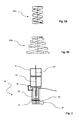
- an electric breaking device 10 comprises two relatively movable contacts 12, 14 housed in an enclosure 16 which can be gastight, and in particular a vacuum interrupter.
- the two contacts 12, 14 are associated with rigid rod-type conductors 22, 24 which make it possible to bring the current between the contacts 12, 14, and which are relatively mobile; in particular, the rods 22, 24 are in the extension of one another to allow movement in translation along their axis.
- the vacuum interrupter 10 is integrated in an electrical energy distribution circuit: a control mechanism for opening or closing the bulb 26 is coupled to a first rod 22 to mobilize it in translation, the second rod 24 being fixed relative to the enclosure 16.
- the first rod 22 is further associated with holding means 30 in the closed position, which use the electrodynamic forces due to the flow of current to exert a contact pressure.
- the holding means comprise a solenoid 32 partially surrounding the first rod 22, to which it is electrically connected.
- the first end 34 of the solenoid is connected to the electrical distribution circuit, and the second end 36 of the solenoid is connected to the rod 22.
- an insulating screen 38 for example a sheath surrounding the rod 22, in order to isolate the latter; advantageously, the sheath 38 extends beyond the solenoid 32 and / or towards the enclosure 16 to also form a screen separating the chamber 16 from the solenoid 32, for example by a disk.
- the solenoid 32 exerts a compressive force on the first contact 12 via the Lorentz forces which cause it to be compressed.
- the first end 34 of the solenoid 32 is rigidly coupled to the chamber 16 of the vacuum bottle 10, in particular by an insulating member 40 integral with the bulb 16 and now fixedly fixed the first turns 34 solenoid 32.
- the second end 36 of the solenoid 32 is rigidly secured to it, in particular by means of a mechanical conductive support 42 forming a pressure medium; the two functions of mechanical and electrical coupling are advantageously filled by the same element, for example a sleeve 42 for holding the last turns 36 of the solenoid 32 associated with a mechanical attachment of screw / nut type.
- the compression of the solenoid 32 causes a displacement of the rod 22 connected to its second end 36, with respect to the enclosure 16 which is coupled to the first 34, by pressure via the link 42: the first end 34 of the solenoid 32 is therefore placed between the second end 36 and the enclosure 16 / the contacts 12, 14.
- the electric current is conveyed via the second rod 24 through the contacts 14, 12 to the first rod 22 and then the link 42 to pass through the solenoid 32 and leave it at its first end 34.
- the current can also be routed to the first end 34 of the solenoid 32 that it passes through to then move in the link 42 to the first rod 22 through the two contacts 12, 14, to exit the bulb 16 by the second rod 24.
- the solenoid 32 is formed by a helically wound conductor of a compression spring 2.
- the spring 32 thus formed can be cylindrical ( figures 2 ), but also prismatic or elliptical, etc. ; the pitch between the turns may be constant or variable, in particular to allow easy attachment to the connecting means 40, 42 to the rod 22 and the enclosure 16; similarly, the propeller may be of constant radius 32A or variable 32B, in particular depending on the available space and the chosen method of attachment.
- the solenoid 32A is composed of 6 mm diameter wire, for example bronze , which may comprise five turns separated from each other by a distance of the order of 14.5 mm, for a mean diameter of 40 mm from the solenoid 32A: the overall size of the holding device 30 remains therefore very limited, less than 4 ⁇ 10 cm, with in addition a simple and inexpensive construction.
- a compression force of 1640 N can be developed by this device 30.
- a ferromagnetic core 44 is coupled to the rod 22 at within the solenoid 32; the coupling can be separated, but it is advantageous to use the same mechanical coupling means 46 for the second end 36 of the solenoid 32 and the core 44, in which case an additional electrical connection 48 is placed between said second end 36 and the rod 22, the mechanical coupling means 46 being made of insulating material, in particular by a cylindrical pin.
- the holding means 50 thus formed then use two electrodynamic forces to exert a pressure between the movable contact 12 and the fixed contact 14: the compression generated by the attraction between them of the turns of the solenoid 32, and the displacement of the ferromagnetic core 42 generated by the passage of current in the solenoid 32 acting for this part as an induction coil.
- the preceding vacuum bulb 10 can in particular be used in a switch as described in the document EP 2 182 536 and illustrated schematically in figure 4 .
- the switch 100 comprises a main conductive line 102 to be connected to the electrical circuit, and provided with a disconnector 104 which can pass from the closed position to the open position of two main contacts 106, 108; the open position preferably corresponds to a grounding 110 by the disconnector 104.
- the main line 102 is provided with a bypass 112 comprising a switchgear device 10 as previously described, but usually remains off: the first end of the branch 112 is certainly connected to the main line, but the second end forms a contact 114 which remains open.
- the vacuum interrupter 10 does not see current flowing, and its contacts are closed.
- the disconnector 104 During its passage from the closed position to the open position, the disconnector 104 passes through an intermediate position of closure of the contact 114 of the branch, the main line remaining closed, then opening the main line 102 while maintaining the contact 114 of the bypass 112 closed: the vacuum bulb 10 then sees all the current for a few milliseconds, and it is she who, thanks to the continued movement of the disconnector 104, ensures the breaking of the current and the opening of the circuit electric.
- this switch 100 can be used for particular applications with high currents during switching (tilting phase between the main circuit 102 and the secondary circuit 112 through the bulb 10): with the architecture of the switch EP 2 182 536 , the holding means 30, 50 make it possible, in addition to keeping the contacts 12, 14 of the vacuum bottle 10 in pressure, to maintain contact between the contact 114 and the knife 108 until the current is cut through Vacuum bulb and opening of the circuit.
Landscapes
- High-Tension Arc-Extinguishing Switches Without Spraying Means (AREA)
- Mechanisms For Operating Contacts (AREA)
Applications Claiming Priority (1)
| Application Number | Priority Date | Filing Date | Title |
|---|---|---|---|
| FR1256356A FR2993092B1 (fr) | 2012-07-03 | 2012-07-03 | Appareil de coupure comprenant des moyens de maintien en fermeture des contacts |
Publications (2)
| Publication Number | Publication Date |
|---|---|
| EP2682970A1 true EP2682970A1 (de) | 2014-01-08 |
| EP2682970B1 EP2682970B1 (de) | 2014-10-22 |
Family
ID=46963879
Family Applications (1)
| Application Number | Title | Priority Date | Filing Date |
|---|---|---|---|
| EP20130305746 Active EP2682970B1 (de) | 2012-07-03 | 2013-06-04 | Schaltgerät mit Mitteln zum geschlossenhalten elektrischer Kontakte |
Country Status (3)
| Country | Link |
|---|---|
| EP (1) | EP2682970B1 (de) |
| ES (1) | ES2525136T3 (de) |
| FR (1) | FR2993092B1 (de) |
Citations (7)
| Publication number | Priority date | Publication date | Assignee | Title |
|---|---|---|---|---|
| US1709947A (en) * | 1922-11-07 | 1929-04-23 | Bbc Brown Boveri & Cie | Electric-switch apparatus |
| FR789153A (fr) * | 1934-03-31 | 1935-10-24 | Delle Atel Const Electr | Contact compensé pour enclenchement sur court-circuit |
| FR1529018A (fr) | 1966-06-16 | 1968-06-14 | Gen Electric | Interrupteur électrique |
| US4030055A (en) * | 1976-02-27 | 1977-06-14 | General Electric Company | Electric circuit breaker with electro-magnetic means for opposing magnetic contact-repulsion forces |
| WO1998001883A1 (en) | 1996-07-05 | 1998-01-15 | Fki Plc | Electrical circuit breakers |
| EP2037475A1 (de) | 2007-09-13 | 2009-03-18 | Eaton Electric B.V. | Betriebsmechanismus mit Einstellung der Kontaktkraft |
| EP2182536A1 (de) | 2008-10-29 | 2010-05-05 | Areva T&D Sas | Stromunterbrechungsschalter in einer Stromleitung, die eine Vakuumlampe umfasst |
-
2012
- 2012-07-03 FR FR1256356A patent/FR2993092B1/fr not_active Expired - Fee Related
-
2013
- 2013-06-04 ES ES13305746.3T patent/ES2525136T3/es active Active
- 2013-06-04 EP EP20130305746 patent/EP2682970B1/de active Active
Patent Citations (7)
| Publication number | Priority date | Publication date | Assignee | Title |
|---|---|---|---|---|
| US1709947A (en) * | 1922-11-07 | 1929-04-23 | Bbc Brown Boveri & Cie | Electric-switch apparatus |
| FR789153A (fr) * | 1934-03-31 | 1935-10-24 | Delle Atel Const Electr | Contact compensé pour enclenchement sur court-circuit |
| FR1529018A (fr) | 1966-06-16 | 1968-06-14 | Gen Electric | Interrupteur électrique |
| US4030055A (en) * | 1976-02-27 | 1977-06-14 | General Electric Company | Electric circuit breaker with electro-magnetic means for opposing magnetic contact-repulsion forces |
| WO1998001883A1 (en) | 1996-07-05 | 1998-01-15 | Fki Plc | Electrical circuit breakers |
| EP2037475A1 (de) | 2007-09-13 | 2009-03-18 | Eaton Electric B.V. | Betriebsmechanismus mit Einstellung der Kontaktkraft |
| EP2182536A1 (de) | 2008-10-29 | 2010-05-05 | Areva T&D Sas | Stromunterbrechungsschalter in einer Stromleitung, die eine Vakuumlampe umfasst |
Non-Patent Citations (1)
| Title |
|---|
| MIEDZINSKI B ET AL: "Effect of a dynamic force compensation in a low voltage vacuum circuit breaker", IEEE AFRICON 2002; [IEEE AFRICON CONFERENCE IN AFRICA], IEEE, vol. 2, 2 October 2002 (2002-10-02), pages 807 - 810, XP010622916, ISBN: 978-0-7803-7570-3, DOI: 10.1109/AFRCON.2002.1160018 * |
Also Published As
| Publication number | Publication date |
|---|---|
| EP2682970B1 (de) | 2014-10-22 |
| FR2993092B1 (fr) | 2015-04-17 |
| FR2993092A1 (fr) | 2014-01-10 |
| ES2525136T3 (es) | 2014-12-17 |
Similar Documents
| Publication | Publication Date | Title |
|---|---|---|
| EP1974363B1 (de) | Schalter zum abschalten eines generator-schutzschalters einer kompaktstruktur | |
| EP1974362B1 (de) | Generator-isolator mit integriertem widerstand | |
| EP1870916B1 (de) | Betätigung eines Lasttrennschalters durch Kulissenzylinder | |
| EP1855300B1 (de) | Trennschalter für einen Wechselstromschalter, der von einem Servomotor betätigt wird | |
| EP2575155B1 (de) | Gerät zur verteilung von strom mittlerer spannung | |
| CA2044517C (fr) | Disjoncteur a varistance incorporee | |
| EP0240397B1 (de) | Selbstbeblasender elektrischer Lastschalter mit rotierendem Lichtbogen | |
| EP3699942B1 (de) | Einschaltsystem einer vakuumschaltröhre | |
| EP2682970B1 (de) | Schaltgerät mit Mitteln zum geschlossenhalten elektrischer Kontakte | |
| EP0204594B1 (de) | Gegen Kurzschlussströme geschütztes Schaltgerät | |
| CA2079555C (fr) | Disjoncteur ultra haute tension | |
| CA2017127C (fr) | Disjoncteur a moyenne tension a courant nominal eleve | |
| EP2619782A1 (de) | Schutzschalter für eine hochspannungsstromleitung mit einer in einem verbindungskanal angeordneten insertionsvorrichtung | |
| EP2575154B1 (de) | Zelle zur Verteilung von Strom mittlerer Spannung | |
| EP0054499B1 (de) | Schalter mit Trennung des Nulleiters | |
| FR2683937A1 (fr) | Disjoncteur hybride pour la coupure des courants a grande composante continue. | |
| EP3226274A1 (de) | Trennschalter mit bogenteilung, der an mittel- und hochspannungen angepasst ist, und abschaltmethode mithilfe dieses trennschalters | |
| FR2464550A1 (fr) | Interrupteur a soufflage magnetique en rotation de l'arc | |
| EP0398116B1 (de) | Mittelspannungsschalter mit Selbstbeblasung | |
| FR3107394A1 (fr) | Appareil de coupure mécanique de courant pour courant continu haute tension avec capacité dans un chemin secondaire, installation et procédé avec un tel appareil | |
| EP0627751A1 (de) | Lastschalter mit doppelter Lichtbogenverlängerung zum Auslösen von Stromen mit grosse Gleichstromkomponente | |
| FR2745949A1 (fr) | Disjoncteur electrique a actionneur electromagnetique et mecanisme de commande | |
| FR2737614A1 (fr) | Deconnecteur-limiteur de protection pour transformateurs electriques triphases | |
| EP3227897A1 (de) | Elektrische tripout-vorrichtung mit einem schutzschalter und isolator | |
| EP3142134A1 (de) | Assistenzsystem zur detektion einer störung eines trennschalters, das an mittel- und hochspannungen angepasst ist |
Legal Events
| Date | Code | Title | Description |
|---|---|---|---|
| PUAI | Public reference made under article 153(3) epc to a published international application that has entered the european phase |
Free format text: ORIGINAL CODE: 0009012 |
|
| AK | Designated contracting states |
Kind code of ref document: A1 Designated state(s): AL AT BE BG CH CY CZ DE DK EE ES FI FR GB GR HR HU IE IS IT LI LT LU LV MC MK MT NL NO PL PT RO RS SE SI SK SM TR |
|
| AX | Request for extension of the european patent |
Extension state: BA ME |
|
| 17P | Request for examination filed |
Effective date: 20140124 |
|
| RBV | Designated contracting states (corrected) |
Designated state(s): AL AT BE BG CH CY CZ DE DK EE ES FI FR GB GR HR HU IE IS IT LI LT LU LV MC MK MT NL NO PL PT RO RS SE SI SK SM TR |
|
| GRAP | Despatch of communication of intention to grant a patent |
Free format text: ORIGINAL CODE: EPIDOSNIGR1 |
|
| RIC1 | Information provided on ipc code assigned before grant |
Ipc: H01H 33/666 20060101ALI20140523BHEP Ipc: H01H 1/54 20060101AFI20140523BHEP |
|
| INTG | Intention to grant announced |
Effective date: 20140702 |
|
| RIN1 | Information on inventor provided before grant (corrected) |
Inventor name: COLIN, M. BRUNO Inventor name: PICCOZ, M. DANIEL |
|
| GRAS | Grant fee paid |
Free format text: ORIGINAL CODE: EPIDOSNIGR3 |
|
| GRAA | (expected) grant |
Free format text: ORIGINAL CODE: 0009210 |
|
| AK | Designated contracting states |
Kind code of ref document: B1 Designated state(s): AL AT BE BG CH CY CZ DE DK EE ES FI FR GB GR HR HU IE IS IT LI LT LU LV MC MK MT NL NO PL PT RO RS SE SI SK SM TR |
|
| REG | Reference to a national code |
Ref country code: GB Ref legal event code: FG4D Free format text: NOT ENGLISH |
|
| REG | Reference to a national code |
Ref country code: CH Ref legal event code: EP |
|
| REG | Reference to a national code |
Ref country code: AT Ref legal event code: REF Ref document number: 692970 Country of ref document: AT Kind code of ref document: T Effective date: 20141115 |
|
| REG | Reference to a national code |
Ref country code: IE Ref legal event code: FG4D Free format text: LANGUAGE OF EP DOCUMENT: FRENCH |
|
| REG | Reference to a national code |
Ref country code: DE Ref legal event code: R096 Ref document number: 602013000387 Country of ref document: DE Effective date: 20141204 |
|
| REG | Reference to a national code |
Ref country code: ES Ref legal event code: FG2A Ref document number: 2525136 Country of ref document: ES Kind code of ref document: T3 Effective date: 20141217 |
|
| REG | Reference to a national code |
Ref country code: NL Ref legal event code: VDEP Effective date: 20141022 |
|
| REG | Reference to a national code |
Ref country code: AT Ref legal event code: MK05 Ref document number: 692970 Country of ref document: AT Kind code of ref document: T Effective date: 20141022 |
|
| REG | Reference to a national code |
Ref country code: LT Ref legal event code: MG4D |
|
| PG25 | Lapsed in a contracting state [announced via postgrant information from national office to epo] |
Ref country code: NL Free format text: LAPSE BECAUSE OF FAILURE TO SUBMIT A TRANSLATION OF THE DESCRIPTION OR TO PAY THE FEE WITHIN THE PRESCRIBED TIME-LIMIT Effective date: 20141022 Ref country code: PT Free format text: LAPSE BECAUSE OF FAILURE TO SUBMIT A TRANSLATION OF THE DESCRIPTION OR TO PAY THE FEE WITHIN THE PRESCRIBED TIME-LIMIT Effective date: 20150223 Ref country code: NO Free format text: LAPSE BECAUSE OF FAILURE TO SUBMIT A TRANSLATION OF THE DESCRIPTION OR TO PAY THE FEE WITHIN THE PRESCRIBED TIME-LIMIT Effective date: 20150122 Ref country code: IS Free format text: LAPSE BECAUSE OF FAILURE TO SUBMIT A TRANSLATION OF THE DESCRIPTION OR TO PAY THE FEE WITHIN THE PRESCRIBED TIME-LIMIT Effective date: 20150222 Ref country code: LT Free format text: LAPSE BECAUSE OF FAILURE TO SUBMIT A TRANSLATION OF THE DESCRIPTION OR TO PAY THE FEE WITHIN THE PRESCRIBED TIME-LIMIT Effective date: 20141022 Ref country code: FI Free format text: LAPSE BECAUSE OF FAILURE TO SUBMIT A TRANSLATION OF THE DESCRIPTION OR TO PAY THE FEE WITHIN THE PRESCRIBED TIME-LIMIT Effective date: 20141022 |
|
| PG25 | Lapsed in a contracting state [announced via postgrant information from national office to epo] |
Ref country code: AT Free format text: LAPSE BECAUSE OF FAILURE TO SUBMIT A TRANSLATION OF THE DESCRIPTION OR TO PAY THE FEE WITHIN THE PRESCRIBED TIME-LIMIT Effective date: 20141022 Ref country code: HR Free format text: LAPSE BECAUSE OF FAILURE TO SUBMIT A TRANSLATION OF THE DESCRIPTION OR TO PAY THE FEE WITHIN THE PRESCRIBED TIME-LIMIT Effective date: 20141022 Ref country code: PL Free format text: LAPSE BECAUSE OF FAILURE TO SUBMIT A TRANSLATION OF THE DESCRIPTION OR TO PAY THE FEE WITHIN THE PRESCRIBED TIME-LIMIT Effective date: 20141022 Ref country code: RS Free format text: LAPSE BECAUSE OF FAILURE TO SUBMIT A TRANSLATION OF THE DESCRIPTION OR TO PAY THE FEE WITHIN THE PRESCRIBED TIME-LIMIT Effective date: 20141022 Ref country code: GR Free format text: LAPSE BECAUSE OF FAILURE TO SUBMIT A TRANSLATION OF THE DESCRIPTION OR TO PAY THE FEE WITHIN THE PRESCRIBED TIME-LIMIT Effective date: 20150123 Ref country code: LV Free format text: LAPSE BECAUSE OF FAILURE TO SUBMIT A TRANSLATION OF THE DESCRIPTION OR TO PAY THE FEE WITHIN THE PRESCRIBED TIME-LIMIT Effective date: 20141022 Ref country code: CY Free format text: LAPSE BECAUSE OF FAILURE TO SUBMIT A TRANSLATION OF THE DESCRIPTION OR TO PAY THE FEE WITHIN THE PRESCRIBED TIME-LIMIT Effective date: 20141022 Ref country code: SE Free format text: LAPSE BECAUSE OF FAILURE TO SUBMIT A TRANSLATION OF THE DESCRIPTION OR TO PAY THE FEE WITHIN THE PRESCRIBED TIME-LIMIT Effective date: 20141022 |
|
| REG | Reference to a national code |
Ref country code: FR Ref legal event code: PLFP Year of fee payment: 3 |
|
| REG | Reference to a national code |
Ref country code: DE Ref legal event code: R097 Ref document number: 602013000387 Country of ref document: DE |
|
| PG25 | Lapsed in a contracting state [announced via postgrant information from national office to epo] |
Ref country code: EE Free format text: LAPSE BECAUSE OF FAILURE TO SUBMIT A TRANSLATION OF THE DESCRIPTION OR TO PAY THE FEE WITHIN THE PRESCRIBED TIME-LIMIT Effective date: 20141022 Ref country code: DK Free format text: LAPSE BECAUSE OF FAILURE TO SUBMIT A TRANSLATION OF THE DESCRIPTION OR TO PAY THE FEE WITHIN THE PRESCRIBED TIME-LIMIT Effective date: 20141022 Ref country code: CZ Free format text: LAPSE BECAUSE OF FAILURE TO SUBMIT A TRANSLATION OF THE DESCRIPTION OR TO PAY THE FEE WITHIN THE PRESCRIBED TIME-LIMIT Effective date: 20141022 Ref country code: RO Free format text: LAPSE BECAUSE OF FAILURE TO SUBMIT A TRANSLATION OF THE DESCRIPTION OR TO PAY THE FEE WITHIN THE PRESCRIBED TIME-LIMIT Effective date: 20141022 Ref country code: SK Free format text: LAPSE BECAUSE OF FAILURE TO SUBMIT A TRANSLATION OF THE DESCRIPTION OR TO PAY THE FEE WITHIN THE PRESCRIBED TIME-LIMIT Effective date: 20141022 |
|
| PLBE | No opposition filed within time limit |
Free format text: ORIGINAL CODE: 0009261 |
|
| STAA | Information on the status of an ep patent application or granted ep patent |
Free format text: STATUS: NO OPPOSITION FILED WITHIN TIME LIMIT |
|
| 26N | No opposition filed |
Effective date: 20150723 |
|
| PG25 | Lapsed in a contracting state [announced via postgrant information from national office to epo] |
Ref country code: MC Free format text: LAPSE BECAUSE OF FAILURE TO SUBMIT A TRANSLATION OF THE DESCRIPTION OR TO PAY THE FEE WITHIN THE PRESCRIBED TIME-LIMIT Effective date: 20141022 |
|
| PG25 | Lapsed in a contracting state [announced via postgrant information from national office to epo] |
Ref country code: LU Free format text: LAPSE BECAUSE OF FAILURE TO SUBMIT A TRANSLATION OF THE DESCRIPTION OR TO PAY THE FEE WITHIN THE PRESCRIBED TIME-LIMIT Effective date: 20150604 Ref country code: SI Free format text: LAPSE BECAUSE OF FAILURE TO SUBMIT A TRANSLATION OF THE DESCRIPTION OR TO PAY THE FEE WITHIN THE PRESCRIBED TIME-LIMIT Effective date: 20141022 |
|
| REG | Reference to a national code |
Ref country code: IE Ref legal event code: MM4A |
|
| PG25 | Lapsed in a contracting state [announced via postgrant information from national office to epo] |
Ref country code: IE Free format text: LAPSE BECAUSE OF NON-PAYMENT OF DUE FEES Effective date: 20150604 |
|
| REG | Reference to a national code |
Ref country code: FR Ref legal event code: PLFP Year of fee payment: 4 |
|
| PG25 | Lapsed in a contracting state [announced via postgrant information from national office to epo] |
Ref country code: MT Free format text: LAPSE BECAUSE OF FAILURE TO SUBMIT A TRANSLATION OF THE DESCRIPTION OR TO PAY THE FEE WITHIN THE PRESCRIBED TIME-LIMIT Effective date: 20141022 |
|
| REG | Reference to a national code |
Ref country code: CH Ref legal event code: PL |
|
| PG25 | Lapsed in a contracting state [announced via postgrant information from national office to epo] |
Ref country code: LI Free format text: LAPSE BECAUSE OF NON-PAYMENT OF DUE FEES Effective date: 20160630 Ref country code: CH Free format text: LAPSE BECAUSE OF NON-PAYMENT OF DUE FEES Effective date: 20160630 |
|
| PG25 | Lapsed in a contracting state [announced via postgrant information from national office to epo] |
Ref country code: BG Free format text: LAPSE BECAUSE OF FAILURE TO SUBMIT A TRANSLATION OF THE DESCRIPTION OR TO PAY THE FEE WITHIN THE PRESCRIBED TIME-LIMIT Effective date: 20141022 Ref country code: HU Free format text: LAPSE BECAUSE OF FAILURE TO SUBMIT A TRANSLATION OF THE DESCRIPTION OR TO PAY THE FEE WITHIN THE PRESCRIBED TIME-LIMIT; INVALID AB INITIO Effective date: 20130604 |
|
| REG | Reference to a national code |
Ref country code: FR Ref legal event code: PLFP Year of fee payment: 5 |
|
| PG25 | Lapsed in a contracting state [announced via postgrant information from national office to epo] |
Ref country code: BE Free format text: LAPSE BECAUSE OF NON-PAYMENT OF DUE FEES Effective date: 20150630 |
|
| PG25 | Lapsed in a contracting state [announced via postgrant information from national office to epo] |
Ref country code: TR Free format text: LAPSE BECAUSE OF FAILURE TO SUBMIT A TRANSLATION OF THE DESCRIPTION OR TO PAY THE FEE WITHIN THE PRESCRIBED TIME-LIMIT Effective date: 20141022 |
|
| GBPC | Gb: european patent ceased through non-payment of renewal fee |
Effective date: 20170604 |
|
| PG25 | Lapsed in a contracting state [announced via postgrant information from national office to epo] |
Ref country code: GB Free format text: LAPSE BECAUSE OF NON-PAYMENT OF DUE FEES Effective date: 20170604 |
|
| PG25 | Lapsed in a contracting state [announced via postgrant information from national office to epo] |
Ref country code: SM Free format text: LAPSE BECAUSE OF FAILURE TO SUBMIT A TRANSLATION OF THE DESCRIPTION OR TO PAY THE FEE WITHIN THE PRESCRIBED TIME-LIMIT Effective date: 20141022 |
|
| REG | Reference to a national code |
Ref country code: FR Ref legal event code: PLFP Year of fee payment: 6 |
|
| PG25 | Lapsed in a contracting state [announced via postgrant information from national office to epo] |
Ref country code: MK Free format text: LAPSE BECAUSE OF FAILURE TO SUBMIT A TRANSLATION OF THE DESCRIPTION OR TO PAY THE FEE WITHIN THE PRESCRIBED TIME-LIMIT Effective date: 20141022 |
|
| PG25 | Lapsed in a contracting state [announced via postgrant information from national office to epo] |
Ref country code: AL Free format text: LAPSE BECAUSE OF FAILURE TO SUBMIT A TRANSLATION OF THE DESCRIPTION OR TO PAY THE FEE WITHIN THE PRESCRIBED TIME-LIMIT Effective date: 20141022 |
|
| PGFP | Annual fee paid to national office [announced via postgrant information from national office to epo] |
Ref country code: DE Payment date: 20250626 Year of fee payment: 13 |
|
| PGFP | Annual fee paid to national office [announced via postgrant information from national office to epo] |
Ref country code: FR Payment date: 20250624 Year of fee payment: 13 |
|
| PGFP | Annual fee paid to national office [announced via postgrant information from national office to epo] |
Ref country code: ES Payment date: 20250710 Year of fee payment: 13 |
|
| PGFP | Annual fee paid to national office [announced via postgrant information from national office to epo] |
Ref country code: IT Payment date: 20250623 Year of fee payment: 13 |