EP2683938B1 - Rotor de turbine éolienne et méthode de montage - Google Patents
Rotor de turbine éolienne et méthode de montage Download PDFInfo
- Publication number
- EP2683938B1 EP2683938B1 EP12708024.0A EP12708024A EP2683938B1 EP 2683938 B1 EP2683938 B1 EP 2683938B1 EP 12708024 A EP12708024 A EP 12708024A EP 2683938 B1 EP2683938 B1 EP 2683938B1
- Authority
- EP
- European Patent Office
- Prior art keywords
- rotor
- support
- base support
- wind turbine
- base
- Prior art date
- Legal status (The legal status is an assumption and is not a legal conclusion. Google has not performed a legal analysis and makes no representation as to the accuracy of the status listed.)
- Withdrawn - After Issue
Links
Images

Classifications
-
- F—MECHANICAL ENGINEERING; LIGHTING; HEATING; WEAPONS; BLASTING
- F03—MACHINES OR ENGINES FOR LIQUIDS; WIND, SPRING, OR WEIGHT MOTORS; PRODUCING MECHANICAL POWER OR A REACTIVE PROPULSIVE THRUST, NOT OTHERWISE PROVIDED FOR
- F03D—WIND MOTORS
- F03D13/00—Assembly, mounting or commissioning of wind motors; Arrangements specially adapted for transporting wind motor components
- F03D13/10—Assembly of wind motors; Arrangements for erecting wind motors
-
- F—MECHANICAL ENGINEERING; LIGHTING; HEATING; WEAPONS; BLASTING
- F03—MACHINES OR ENGINES FOR LIQUIDS; WIND, SPRING, OR WEIGHT MOTORS; PRODUCING MECHANICAL POWER OR A REACTIVE PROPULSIVE THRUST, NOT OTHERWISE PROVIDED FOR
- F03D—WIND MOTORS
- F03D1/00—Wind motors with rotation axis substantially parallel to the air flow entering the rotor
- F03D1/06—Rotors
-
- F—MECHANICAL ENGINEERING; LIGHTING; HEATING; WEAPONS; BLASTING
- F03—MACHINES OR ENGINES FOR LIQUIDS; WIND, SPRING, OR WEIGHT MOTORS; PRODUCING MECHANICAL POWER OR A REACTIVE PROPULSIVE THRUST, NOT OTHERWISE PROVIDED FOR
- F03D—WIND MOTORS
- F03D13/00—Assembly, mounting or commissioning of wind motors; Arrangements specially adapted for transporting wind motor components
- F03D13/20—Arrangements for mounting or supporting wind motors; Masts or towers for wind motors
-
- F—MECHANICAL ENGINEERING; LIGHTING; HEATING; WEAPONS; BLASTING
- F03—MACHINES OR ENGINES FOR LIQUIDS; WIND, SPRING, OR WEIGHT MOTORS; PRODUCING MECHANICAL POWER OR A REACTIVE PROPULSIVE THRUST, NOT OTHERWISE PROVIDED FOR
- F03D—WIND MOTORS
- F03D80/00—Details, components or accessories not provided for in groups F03D1/00 - F03D17/00
-
- F—MECHANICAL ENGINEERING; LIGHTING; HEATING; WEAPONS; BLASTING
- F05—INDEXING SCHEMES RELATING TO ENGINES OR PUMPS IN VARIOUS SUBCLASSES OF CLASSES F01-F04
- F05B—INDEXING SCHEME RELATING TO WIND, SPRING, WEIGHT, INERTIA OR LIKE MOTORS, TO MACHINES OR ENGINES FOR LIQUIDS COVERED BY SUBCLASSES F03B, F03D AND F03G
- F05B2230/00—Manufacture
- F05B2230/60—Assembly methods
- F05B2230/61—Assembly methods using auxiliary equipment for lifting or holding
-
- F—MECHANICAL ENGINEERING; LIGHTING; HEATING; WEAPONS; BLASTING
- F05—INDEXING SCHEMES RELATING TO ENGINES OR PUMPS IN VARIOUS SUBCLASSES OF CLASSES F01-F04
- F05B—INDEXING SCHEME RELATING TO WIND, SPRING, WEIGHT, INERTIA OR LIKE MOTORS, TO MACHINES OR ENGINES FOR LIQUIDS COVERED BY SUBCLASSES F03B, F03D AND F03G
- F05B2240/00—Components
- F05B2240/10—Stators
- F05B2240/14—Casings, housings, nacelles, gondels or the like, protecting or supporting assemblies there within
-
- F—MECHANICAL ENGINEERING; LIGHTING; HEATING; WEAPONS; BLASTING
- F05—INDEXING SCHEMES RELATING TO ENGINES OR PUMPS IN VARIOUS SUBCLASSES OF CLASSES F01-F04
- F05B—INDEXING SCHEME RELATING TO WIND, SPRING, WEIGHT, INERTIA OR LIKE MOTORS, TO MACHINES OR ENGINES FOR LIQUIDS COVERED BY SUBCLASSES F03B, F03D AND F03G
- F05B2240/00—Components
- F05B2240/20—Rotors
- F05B2240/21—Rotors for wind turbines
- F05B2240/221—Rotors for wind turbines with horizontal axis
-
- F—MECHANICAL ENGINEERING; LIGHTING; HEATING; WEAPONS; BLASTING
- F16—ENGINEERING ELEMENTS AND UNITS; GENERAL MEASURES FOR PRODUCING AND MAINTAINING EFFECTIVE FUNCTIONING OF MACHINES OR INSTALLATIONS; THERMAL INSULATION IN GENERAL
- F16C—SHAFTS; FLEXIBLE SHAFTS; ELEMENTS OR CRANKSHAFT MECHANISMS; ROTARY BODIES OTHER THAN GEARING ELEMENTS; BEARINGS
- F16C2360/00—Engines or pumps
- F16C2360/31—Wind motors
-
- Y—GENERAL TAGGING OF NEW TECHNOLOGICAL DEVELOPMENTS; GENERAL TAGGING OF CROSS-SECTIONAL TECHNOLOGIES SPANNING OVER SEVERAL SECTIONS OF THE IPC; TECHNICAL SUBJECTS COVERED BY FORMER USPC CROSS-REFERENCE ART COLLECTIONS [XRACs] AND DIGESTS
- Y02—TECHNOLOGIES OR APPLICATIONS FOR MITIGATION OR ADAPTATION AGAINST CLIMATE CHANGE
- Y02E—REDUCTION OF GREENHOUSE GAS [GHG] EMISSIONS, RELATED TO ENERGY GENERATION, TRANSMISSION OR DISTRIBUTION
- Y02E10/00—Energy generation through renewable energy sources
- Y02E10/70—Wind energy
- Y02E10/72—Wind turbines with rotation axis in wind direction
-
- Y—GENERAL TAGGING OF NEW TECHNOLOGICAL DEVELOPMENTS; GENERAL TAGGING OF CROSS-SECTIONAL TECHNOLOGIES SPANNING OVER SEVERAL SECTIONS OF THE IPC; TECHNICAL SUBJECTS COVERED BY FORMER USPC CROSS-REFERENCE ART COLLECTIONS [XRACs] AND DIGESTS
- Y02—TECHNOLOGIES OR APPLICATIONS FOR MITIGATION OR ADAPTATION AGAINST CLIMATE CHANGE
- Y02E—REDUCTION OF GREENHOUSE GAS [GHG] EMISSIONS, RELATED TO ENERGY GENERATION, TRANSMISSION OR DISTRIBUTION
- Y02E10/00—Energy generation through renewable energy sources
- Y02E10/70—Wind energy
- Y02E10/727—Offshore wind turbines
-
- Y—GENERAL TAGGING OF NEW TECHNOLOGICAL DEVELOPMENTS; GENERAL TAGGING OF CROSS-SECTIONAL TECHNOLOGIES SPANNING OVER SEVERAL SECTIONS OF THE IPC; TECHNICAL SUBJECTS COVERED BY FORMER USPC CROSS-REFERENCE ART COLLECTIONS [XRACs] AND DIGESTS
- Y02—TECHNOLOGIES OR APPLICATIONS FOR MITIGATION OR ADAPTATION AGAINST CLIMATE CHANGE
- Y02E—REDUCTION OF GREENHOUSE GAS [GHG] EMISSIONS, RELATED TO ENERGY GENERATION, TRANSMISSION OR DISTRIBUTION
- Y02E10/00—Energy generation through renewable energy sources
- Y02E10/70—Wind energy
- Y02E10/728—Onshore wind turbines
-
- Y—GENERAL TAGGING OF NEW TECHNOLOGICAL DEVELOPMENTS; GENERAL TAGGING OF CROSS-SECTIONAL TECHNOLOGIES SPANNING OVER SEVERAL SECTIONS OF THE IPC; TECHNICAL SUBJECTS COVERED BY FORMER USPC CROSS-REFERENCE ART COLLECTIONS [XRACs] AND DIGESTS
- Y10—TECHNICAL SUBJECTS COVERED BY FORMER USPC
- Y10T—TECHNICAL SUBJECTS COVERED BY FORMER US CLASSIFICATION
- Y10T29/00—Metal working
- Y10T29/49—Method of mechanical manufacture
- Y10T29/49316—Impeller making
Definitions
- the invention relates to wind turbine rotors and methods of mounting and installing wind turbine rotors.
- the invention is applicable to both offshore and onshore applications.
- wind turbines both offshore (at sea) and onshore (on land) for the purpose of converting wind energy into other forms of energy, such as electrical energy.
- the typical method for installing a wind turbine rotor is one of the following:
- the invention provides a wind turbine rotor assembly, and a method of mounting a wind turbine rotor, as set out in the accompanying claims.
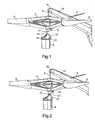
- Figure 1 shows step 1 in a method of mounting a rotor 2 on a supporting tower 4.
- the rotor 2 has three blades 6, and the weight of the rotor is typically in the range of 50 to 400 tonnes (ie. 50,000 to 400,000 Kg).
- the rotor is suspended in a generally horizontal position by the crane wire 8 of a crane 10. In this position the blades 6 of the rotor 2 lie in a substantially horizontal plane, and the intended axis of rotation 12 of the rotor 2 is substantially vertical, as shown in Figure 1 .
- the crane wire 8 runs over a wheel 14 at the tip of crane 10.
- the portion of crane wire 8 between the wheel 14 and the rotor 2 is vertical and generally in line with the intended axis of rotation 12 of the rotor 2.
- a rotor support 16 which is a supporting structure which is rotatably mounted to the rest of the rotor 2.
- the rotor support 16 is provided with two hooks or hook structures 21.
- the top of the supporting tower 4 is provided with a base support structure 18, which is bolted to the supporting tower 4 by bolts 20.
- the base support 18 is provided with a hook receiving structure 22 (described in greater detail below) which is arranged to receive, and engage with, the hook structures 21 in order to form a hinged connection between the rotor support 16 and the base support 18.
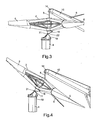
- Figure 2 shows step 2 in the process, in which the rotor 2 is lowered, for example by extending the crane wire 8 over the wheel 14, until the hooks 21 are adjacent to, and at approximately the same height as, the receiving structure 22 on the base support 18.
- FIG. 5 shows an offshore embodiment in which the tower 4 is mounted on the seabed 24 and the crane 10 is mounted on a boat 26. Onshore embodiments are also possible.
- the method described has the advantage that the entire rotor can be pre-assembled in a horizontal position onshore, transported to the wind turbine and than installed onto the wind turbine in one piece using only one crane.
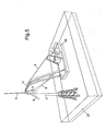
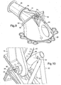
- FIG 6 shows the base support 18 in greater detail.
- the base support 18 is provided with a generally circular flange 28 provided with apertures 29 which allow the base support 18 to be bolted to the supporting tower 4 as shown in Figure 1 .
- the other end of the base support 18 is provided with a base support flange 30, which we refer to hereinafter as base support flange 30, and which lies in a plane which is at about 45° relative to the plane containing the first flange 28.
- FIG. 6 also shows the receiving structure 22 in greater detail.
- the receiving structure 22 is positioned adjacent the base support flange 30, and defines two semi-cylindrical, or partially cylindrical, recesses 32, each of which extends along an axis which is substantially horizontal in use, and which lies parallel with a plane containing the base support flange 30.
- a generally circular or part-circular recess 34 At the inside end of each semi-cylindrical recess 32 there is defined a generally circular or part-circular recess 34.
- Figure 7 shows the rotor support 16 in greater detail.
- the rotor support 16 is shown rotatably mounted to the axle 36 of the rotor 2.
- the axle 36 is provided with a bearing section 38.
- the rotor support 16 is provided with a generally circular rotor support flange 42 which lies in a plane which intersects the axis of rotation 44 of the rotor axle 36, and hence also of rotor 2, at an angle of about 45°.
- the rotor support flange 42 is provided with a series of apertures 46 which are designed to align with apertures 48 in the base support flange 30 shown in Figure 6 . This allows the rotor support flange 42 to be bolted securely to said base support flange 30 when the rotor reaches its final position shown in Figure 5 .
- FIG 7 also shows the hook structures 21 of the rotor support 16 in greater detail.
- Each hook structure 21 is provided with a generally cylindrical portion 48, which is adapted to fit snugly into a respective one of said semi-cylindrical recesses 32 in order to form a hinged connection between the rotor support 16 and the base support 18.
- a circular protrusion 50 which is adapted to fit snugly into a respect one of said circular recesses 34 formed in the receiving structure 22.
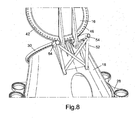
- Figure 8 shows the rotor support 16 engaged with the base support 18 in the initial position shown in Figure 3 .
- Figure 8 also shows a primary horizontal guiding system 52 which is provided on the base support 18.
- This guiding system 52 comprises two curved tubular guides which guide the hooks structures 21 into the receiving structure 22 as the rotor support 16 is moved towards the base support 18.
- a hydraulic damping cylinder (not shown) is also mounted in the vertical direction to avoid large vertical impact loads between the rotor support 16 and the base support 18 when these structures first make contact.
- Figure 9 shows the rotor support 16 engaged with the base support 18 in the final position of Figure 5 .
- Figure 10 shows one of the hook structures 21 engaged in the receiving structure 22.
- the circular protrusion 50 fits snugly within the circular recess 34 in order to prevent the hook structure 21 from slipping away from the base support flange 30 of the base support 18.
- the rotor support flange 42 lies in a plane which is inclined at an angle of 45 degrees relative to rotor axis of rotation 44.
- the rotor support flange 42 abuts the base support flange 30 in order to limit the hinged movement of the rotor support 16 and hence define the final position of the rotor support 16 shown in Figure 9 .
- the base support flange 30 also lies in a plane which lies at 45 degrees to the rotor axis 44.
- the flanges 30 and 42 may be inclined at different angles. Ideally the flanges 30 and 42 are arranged in planes which are not perpendicular to the rotor axis 44 or to the central longitudinal axis of the tower itself, and in general a range of angles between 10 and 80 degrees relative to the rotor axis 44 are possible. It should also be understood that the flanges 30 and 42 do not have to be completely flat, and could for example by made slightly wavy or have another profile. In this case the flanges 30 and 42 would not be completely planar, but would lie generally within a plane.
- a fixed shaft (the rotor support 16) for the rotor is normally preferred. This has the advantage of small fatigue loadings since the shaft do not see cyclic gravity loading from the weight of the rotor in contrast to a rotating shaft.
- the rotor for such a construction is normally mounted to the fixed shaft (the rotor support 16) via one or two main bearings.
- the fixed shaft (rotor support 16) is then normally bolted to the nacelle main frame (the base support 18) during the installation of the rotor.
- the nacelle main frame carries the load from the fixed shaft via a bend of approximately 80-90 degrees to connect to the yaw bearing at the top of the supporting wind turbine tower.
- the minimum size of the bearing will dictate the size of the shaft (the rotor support 16) diameter.
- the most critical part of the structural integrity of the fixed shaft ( rotor support 16) is normally the bolted flange connection.
- the diameter of the fixed shaft is therefore often driven by the necessary size of the flange which again might drive the inner diameter of the bearing (assuming the fatigue life of the bearing is satisfactory) and hence the cost of the bearings.
- the flanges 30 and 42 between the rotor support 16 and the base support 18 are arranged within the bend between the fixed shaft longitudinal axis and the tower axis.
- the preferred flange face plane is approximately 45 degrees to the rotor axis of rotation thereby increasing the flange diameter by approximately the square root of 2 and the moment of resistance to withstand bending moment by 2 (100% increase) assuming unchanged bolt diameter.
- both the rotor support flange 42 and base support flange 30 are circular.
- the bearing arrangement 38 and the flange 28 are also circular, and the rotor support 16 and base support 18 are therefore both shaped so as to allow both ends of each support 16 and 18 to be circular.
- Circular flanges can have the advantage of being easier to machine, and also of avoiding excessive strain on any particular bolts around the circumference of the flange.
- the rotor support flange 42 and base support flange 30 are elliptical or have different shapes.
Landscapes
- Engineering & Computer Science (AREA)
- Life Sciences & Earth Sciences (AREA)
- Sustainable Development (AREA)
- Sustainable Energy (AREA)
- Chemical & Material Sciences (AREA)
- Combustion & Propulsion (AREA)
- Mechanical Engineering (AREA)
- General Engineering & Computer Science (AREA)
- Wind Motors (AREA)
- Structures Of Non-Positive Displacement Pumps (AREA)
Claims (15)
- Assemblage de rotor de turbine éolienne, comprenant :un support de rotor (16) ;un rotor (2), monté de manière rotative sur le support du rotor (16) ; etun support de base (18) ;dans lequel le support du rotor (16) et le support de base (18) comportent un moyen d'engagement permettant au support du rotor (16) et au support de base (18) de s'engager l'un dans l'autre, de sorte que lorsque le support du rotor (16) et le support de base (18) sont déplacés ensemble, une connexion articulée est formée entre le support du rotor (16) et le support de base (18), cette connexion articulée permettant la rotation du support du rotor (16) par rapport au support de base (18) au cours de l'installation ou du démantèlement du rotor (2).
- Assemblage de rotor de turbine éolienne selon la revendication 1, dans lequel le support du rotor et le support de base sont agencés de sorte à être connectés de manière amovible l'un à l'autre lorsque le support du rotor et le support de base sont déplacés ensemble.
- Assemblage de rotor de turbine éolienne selon les revendications 1 ou 2, dans lequel ladite connexion articulée est destinée à permettre une articulation dudit rotor et dudit support du rotor autour d'un axe essentiellement horizontal en service.
- Assemblage de rotor de turbine éolienne selon l'une quelconque des revendications précédentes, dans lequel ledit moyen d'engagement comprend au moins une partie d'accouplement mâle, ladite partie d'accouplement mâle étant agencée sur au moins un support, ledit support du rotor ou ledit support de base.
- Assemblage de rotor de turbine éolienne selon la revendication 4, dans lequel ladite partie d'accouplement mâle englobe au moins un crochet.
- Assemblage de rotor de turbine éolienne selon les revendications 4 ou 5, dans lequel ladite partie d'accouplement mâle comprend au moins une partie cylindrique, pouvant avoir une forme cylindrique, semi-cylindrique ou partiellement cylindrique, et dans lequel ladite partie cylindrique comporte un axe longitudinal formant en service l'axe de rotation d'une connexion articulée entre ledit support du rotor et ledit support de base.
- Assemblage de rotor de turbine éolienne selon la revendication 6, dans lequel ladite partie d'accouplement mâle comporte une saillie généralement circulaire, ladite saillie généralement circulaire étant agencée au niveau de l'extrémité de ladite partie cylindrique.
- Assemblage de rotor de turbine éolienne selon l'une quelconque des revendications 4 à 7, dans lequel ledit moyen d'engagement comprend au moins un évidement, ledit évidement étant agencé sur au moins un support, ledit support du rotor ou ledit support de base, ledit évidement étant adapté pour recevoir ladite partie d'accouplement mâle pour former ladite liaison entre le support du rotor et le support de base.
- Assemblage de rotor de turbine éolienne selon l'une quelconque des revendications précédentes, dans lequel une structure de guidage est prévue pour guider ledit support du rotor et ledit support de base en vue de leur engagement mutuel lorsque ledit support du rotor et ledit support de base sont déplacés ensemble pour former ladite liaison.
- Assemblage de rotor de turbine éolienne selon la revendication 1, dans lequel ladite structure de guidage comprend au moins deux éléments de guidage, et dans lequel la distance entre lesdits deux éléments de guidage diminue avec la diminution de la distance par rapport audit support de base.
- Assemblage de rotor de turbine éolienne selon l'une quelconque des revendications précédentes, dans lequel :ledit rotor est monté de manière rotative sur ledit support du rotor, autour d'un axe du rotor ;ledit support du rotor comporte une surface du support du rotor, se situant en général dans un premier plan ;ledit support de base comporte une surface du support de base se situant en général dans un deuxième plan ;ladite surface du support du rotor et ladite surface du support de base sont agencées de sorte à buter l'une contre l'autre pour limiter la rotation du support du rotor et définir ainsi une position finale pour ledit support du rotor ; etledit premier plan est agencé à un angle, de sorte qu'il n'est pas perpendiculaire audit axe du rotor.
- Assemblage de rotor de turbine éolienne selon la revendication 11, dans lequel ledit premier plan est agencé à un angle compris entre 10 et 80 degrés par rapport audit axe du rotor.
- Procédé de montage d'un rotor de turbine éolienne sur un support de base, ledit rotor étant monté de manière rotative sur un support du rotor, ledit procédé comprenant les étapes ci-dessous :suspension dudit rotor dans une position généralement horizontale ;déplacement dudit support du rotor en vue de son engagement dans ledit support de base, pour former une connexion articulée entre le support du rotor et le support de base ; etrotation dudit support du rotor par rapport audit support de base autour de ladite connexion articulée, de sorte à faire tourner ledit rotor de ladite position généralement horizontale vers une position généralement verticale.
- Procédé selon la revendication 13, dans lequel ledit rotor, ledit support du rotor et ledit support de base font partie d'un assemblage de rotor de turbine éolienne présentant les caractéristiques selon l'une quelconque des revendications 1 à 12.
- Procédé selon les revendications 13 ou 14, dans lequel ladite étape de rotation dudit support du rotor englobe la rotation dudit support du rotor par l'intermédiaire d'un abaissement de la hauteur au niveau de laquelle ledit rotor est suspendu.
Applications Claiming Priority (2)
| Application Number | Priority Date | Filing Date | Title |
|---|---|---|---|
| GB1103971.6A GB2488803B (en) | 2011-03-09 | 2011-03-09 | Wind turbine rotors and methods of mounting |
| PCT/EP2012/054097 WO2012120115A1 (fr) | 2011-03-09 | 2012-03-09 | Rotor de turbine éolienne et méthode de montage |
Publications (2)
| Publication Number | Publication Date |
|---|---|
| EP2683938A1 EP2683938A1 (fr) | 2014-01-15 |
| EP2683938B1 true EP2683938B1 (fr) | 2015-10-21 |
Family
ID=43923418
Family Applications (1)
| Application Number | Title | Priority Date | Filing Date |
|---|---|---|---|
| EP12708024.0A Withdrawn - After Issue EP2683938B1 (fr) | 2011-03-09 | 2012-03-09 | Rotor de turbine éolienne et méthode de montage |
Country Status (9)
| Country | Link |
|---|---|
| US (1) | US9500178B2 (fr) |
| EP (1) | EP2683938B1 (fr) |
| JP (1) | JP2014507601A (fr) |
| KR (1) | KR20140061297A (fr) |
| CN (1) | CN103429887B (fr) |
| AU (1) | AU2012224580B2 (fr) |
| BR (1) | BR112013021744A2 (fr) |
| GB (1) | GB2488803B (fr) |
| WO (1) | WO2012120115A1 (fr) |
Families Citing this family (7)
| Publication number | Priority date | Publication date | Assignee | Title |
|---|---|---|---|---|
| JP5984792B2 (ja) * | 2013-12-27 | 2016-09-06 | 三菱重工業株式会社 | 風力発電装置 |
| DE102014001421B4 (de) * | 2014-02-03 | 2015-10-22 | Skywind Gmbh | Positionier-Vorrichtung für eine Turbine einer Windenergieanlage |
| DK2924281T3 (en) * | 2014-03-25 | 2018-12-10 | Siemens Ag | Support structure of a wind turbine |
| GB201508550D0 (en) | 2015-05-19 | 2015-07-01 | Rolls Royce Plc | Improved alignment of flanged components |
| CN105000462B (zh) * | 2015-06-11 | 2017-01-11 | 山东电力建设第一工程公司 | 5mw陆上型风力发电机组分体式吊装方法 |
| CN108757337B (zh) * | 2018-07-16 | 2023-06-23 | 中国能源建设集团安徽省电力设计院有限公司 | 一种用于风机安装的高低平台象腿工装 |
| CN116066303B (zh) * | 2023-03-07 | 2023-06-09 | 山西省安装集团股份有限公司 | 一种风电机组底座吊装结构及装置 |
Family Cites Families (23)
| Publication number | Priority date | Publication date | Assignee | Title |
|---|---|---|---|---|
| JPS56143369A (en) * | 1980-04-07 | 1981-11-09 | Agency Of Ind Science & Technol | Wind force prime mover using propeller |
| JPH11255596A (ja) * | 1998-03-12 | 1999-09-21 | Super Silicon Kenkyusho:Kk | 単結晶インゴットハンドリング装置及び単結晶インゴットハンドリング用治具及び単結晶インゴットハンドリング用治具アセンブリ並びに単結晶インゴットハンドリング方法 |
| DE10021163B4 (de) * | 2000-04-29 | 2006-03-02 | Aerodyn Engineering Gmbh | Wasserfahrzeug zum Versorgen einer Offshore-Windenergieanlage |
| US6278198B1 (en) * | 2000-05-02 | 2001-08-21 | Valmont Industries, Inc. | Method and means for mounting a wind turbine on a tower |
| US20010038207A1 (en) * | 2000-05-02 | 2001-11-08 | Willis Jeffrey O. | Method and means for mounting a wind turbine on a tower |
| US7218013B2 (en) * | 2001-10-17 | 2007-05-15 | Steve Anderson Platt | Wind powered generator |
| DE10205988B4 (de) * | 2002-02-14 | 2006-02-09 | Aloys Wobben | Windenergieanlage |
| NO317431B1 (no) | 2002-05-22 | 2004-10-25 | Sway As | Anordning ved vindkraftverk pa dypt vann |
| BR0215738B1 (pt) * | 2002-05-27 | 2011-12-27 | mÉtodos de manipulaÇço de lÂminas de turbina de vento e montagem de referidas lÂminas sobre uma turbina de vento, sistema e unidade de agarramento para a manipulaÇço de uma lÂmina de turbina de vento. | |
| US6857508B2 (en) * | 2002-10-31 | 2005-02-22 | Inventio Ag | Elevator hoist machine installation apparatus |
| CN101173652B (zh) * | 2003-09-19 | 2011-08-24 | 通用电气公司 | 轴承箱 |
| NO20054704D0 (no) * | 2005-10-13 | 2005-10-13 | Sway As | Fremgangsmate og metode for vindkraftverk og fremdriftssystem med magnetisk stabilt hovedlager og lastkontrollsystem |
| US7442009B2 (en) * | 2006-01-06 | 2008-10-28 | Hamilton Sundstrand Corporation | Driving device for raising or lowering an airfoil |
| US8069634B2 (en) * | 2006-10-02 | 2011-12-06 | General Electric Company | Lifting system and apparatus for constructing and enclosing wind turbine towers |
| DE102007019513B4 (de) * | 2007-04-25 | 2012-03-15 | Aerodyn Engineering Gmbh | Windenergieanlage |
| JP5055023B2 (ja) * | 2007-05-25 | 2012-10-24 | 三菱重工業株式会社 | 風力発電装置のロータ取付け方法および風力発電装置の建設方法 |
| CN101878178B (zh) * | 2007-11-29 | 2014-05-28 | 维斯塔斯风力系统有限公司 | 在站点建立风力涡轮机的方法、风力涡轮机塔的运输、风力涡轮机塔和适合运输风力涡轮机塔的船 |
| DE102008047341A1 (de) * | 2008-09-15 | 2010-04-15 | Daubner & Stommel GbR Bau-Werk-Planung (vertretungsberechtigter Gesellschafter: Matthias Stommel, 27777 Ganderkesee) | Verfahren zum Hochheben von Komponenten von Windenergieanlagen |
| US20100117368A1 (en) * | 2008-11-07 | 2010-05-13 | Benito Pedro | Drive train supporting structure for a wind turbine |
| DE102009008437A1 (de) * | 2009-02-11 | 2010-08-12 | Vensys Energy Ag | Maschinenträger zur Aufnahme einer Rotor-/ Generatorbaugruppe einer getriebelosen Windenenergieanlage |
| WO2011006526A1 (fr) | 2009-07-13 | 2011-01-20 | Vsl International Ag | Ensemble tour télescopique et procédé associé |
| US8496423B2 (en) * | 2009-09-10 | 2013-07-30 | National Oilwell Varco, L.P. | Windmill conveyance system and method for using same |
| DE102009041982A1 (de) * | 2009-09-17 | 2011-04-14 | Schuler Pressen Gmbh & Co. Kg | Verfahren zur Leitungsmontage im Turm einer Windkraftanlage |
-
2011
- 2011-03-09 GB GB1103971.6A patent/GB2488803B/en not_active Expired - Fee Related
-
2012
- 2012-03-09 AU AU2012224580A patent/AU2012224580B2/en not_active Ceased
- 2012-03-09 WO PCT/EP2012/054097 patent/WO2012120115A1/fr not_active Ceased
- 2012-03-09 US US14/003,742 patent/US9500178B2/en not_active Expired - Fee Related
- 2012-03-09 EP EP12708024.0A patent/EP2683938B1/fr not_active Withdrawn - After Issue
- 2012-03-09 BR BR112013021744A patent/BR112013021744A2/pt not_active Application Discontinuation
- 2012-03-09 KR KR1020137023447A patent/KR20140061297A/ko not_active Ceased
- 2012-03-09 CN CN201280012409.4A patent/CN103429887B/zh not_active Expired - Fee Related
- 2012-03-09 JP JP2013557111A patent/JP2014507601A/ja active Pending
Also Published As
| Publication number | Publication date |
|---|---|
| US20140072430A1 (en) | 2014-03-13 |
| GB2488803A (en) | 2012-09-12 |
| CN103429887A (zh) | 2013-12-04 |
| KR20140061297A (ko) | 2014-05-21 |
| AU2012224580B2 (en) | 2017-02-23 |
| CN103429887B (zh) | 2016-06-08 |
| GB201103971D0 (en) | 2011-04-20 |
| US9500178B2 (en) | 2016-11-22 |
| AU2012224580A1 (en) | 2013-10-10 |
| EP2683938A1 (fr) | 2014-01-15 |
| WO2012120115A1 (fr) | 2012-09-13 |
| GB2488803B (en) | 2013-04-17 |
| BR112013021744A2 (pt) | 2016-11-01 |
| JP2014507601A (ja) | 2014-03-27 |
Similar Documents
| Publication | Publication Date | Title |
|---|---|---|
| EP2683938B1 (fr) | Rotor de turbine éolienne et méthode de montage | |
| EP2868914B1 (fr) | Dispositif et procédé permettant d'attacher et de détacher une pale pour éolienne | |
| EP2505823B1 (fr) | Trame de transport pour unité de moyeu de rotor/nacelle d'une éolienne, procédé de transport et de montage d'une unité de moyeu de rotor/nacelle | |
| EP3394427B1 (fr) | Procédés de montage ou de démontage d'un composant d'éolienne d'une éolienne à rotors multiples | |
| EP3191707B1 (fr) | Système et procédé pour retirer et/ou installer une pale de rotor d'une éolienne | |
| EP3394426B1 (fr) | Procédés pour monter ou démonter des éléments d'éolienne d'une éolienne à rotors multiples | |
| EP3612730B1 (fr) | Nacelle de turbine éolienne et procédé d'assemblage et démontage d'une éolienne et système d'éolienne | |
| EP2832988A1 (fr) | Procédé et appareil pour manipuler une pale de rotor | |
| WO2013051167A1 (fr) | Dispositif et procédé de fixation et détachement d'aubes pour éolienne | |
| EP2584190A2 (fr) | Nacelle et tour de levage | |
| KR101338407B1 (ko) | 풍력발전기 블레이드의 이동장치 | |
| EP3070044B1 (fr) | Systèmes et procédés de levage | |
| CN102762849A (zh) | 风轮机桨叶放下设备 | |
| CN103423100B (zh) | 在生产或安装期间旋转风力涡轮机的叶片或叶片部件的方法和设备 | |
| KR101408274B1 (ko) | 풍력발전기 블레이드의 수평이동장치 | |
| WO2020047104A1 (fr) | Ensemble contrepoids destiné à être utilisé pendant le montage pale après pale du rotor d'une éolienne | |
| US10641042B2 (en) | External ladder assembly for wind turbine nacelle | |
| CN106801660A (zh) | 用于安装风力发电机的叶片的方法及设备 | |
| EP3875753B1 (fr) | Procédé d'installation d'aube d'éolienne | |
| CN102678474A (zh) | 用于安装水上风力涡轮机的船和方法 | |
| GB2577643A (en) | Method for assembling a wind turbine and a wind turbine system | |
| CN110914532A (zh) | 用于转矩轴承的提升系统、用于安装和拆卸转矩轴承的方法以及这种提升系统的应用 | |
| EP2532879B1 (fr) | Montage et/ou maintenance d'une éolienne | |
| WO2013068008A1 (fr) | Dispositif de guidage femelle et ensemble de guidage pour guider l'assemblage de deux segments de pale de rotor d'une turbine éolienne |
Legal Events
| Date | Code | Title | Description |
|---|---|---|---|
| PUAI | Public reference made under article 153(3) epc to a published international application that has entered the european phase |
Free format text: ORIGINAL CODE: 0009012 |
|
| 17P | Request for examination filed |
Effective date: 20130812 |
|
| AK | Designated contracting states |
Kind code of ref document: A1 Designated state(s): AL AT BE BG CH CY CZ DE DK EE ES FI FR GB GR HR HU IE IS IT LI LT LU LV MC MK MT NL NO PL PT RO RS SE SI SK SM TR |
|
| DAX | Request for extension of the european patent (deleted) | ||
| GRAP | Despatch of communication of intention to grant a patent |
Free format text: ORIGINAL CODE: EPIDOSNIGR1 |
|
| INTG | Intention to grant announced |
Effective date: 20150410 |
|
| RBV | Designated contracting states (corrected) |
Designated state(s): AL AT BE BG CH CY CZ DE DK EE ES FI FR GR HR HU IE IS IT LI LT LU LV MC MK MT NL NO PL PT RO RS SE SI SK SM TR |
|
| GRAS | Grant fee paid |
Free format text: ORIGINAL CODE: EPIDOSNIGR3 |
|
| GRAA | (expected) grant |
Free format text: ORIGINAL CODE: 0009210 |
|
| AK | Designated contracting states |
Kind code of ref document: B1 Designated state(s): AL AT BE BG CH CY CZ DE DK EE ES FI FR GR HR HU IE IS IT LI LT LU LV MC MK MT NL NO PL PT RO RS SE SI SK SM TR |
|
| REG | Reference to a national code |
Ref country code: NL Ref legal event code: MP Effective date: 20151021 |
|
| REG | Reference to a national code |
Ref country code: CH Ref legal event code: EP |
|
| REG | Reference to a national code |
Ref country code: AT Ref legal event code: REF Ref document number: 756785 Country of ref document: AT Kind code of ref document: T Effective date: 20151115 |
|
| REG | Reference to a national code |
Ref country code: IE Ref legal event code: FG4D |
|
| REG | Reference to a national code |
Ref country code: DE Ref legal event code: R096 Ref document number: 602012011775 Country of ref document: DE |
|
| REG | Reference to a national code |
Ref country code: LT Ref legal event code: MG4D |
|
| REG | Reference to a national code |
Ref country code: AT Ref legal event code: MK05 Ref document number: 756785 Country of ref document: AT Kind code of ref document: T Effective date: 20151021 |
|
| PG25 | Lapsed in a contracting state [announced via postgrant information from national office to epo] |
Ref country code: NL Free format text: LAPSE BECAUSE OF FAILURE TO SUBMIT A TRANSLATION OF THE DESCRIPTION OR TO PAY THE FEE WITHIN THE PRESCRIBED TIME-LIMIT Effective date: 20151021 Ref country code: HR Free format text: LAPSE BECAUSE OF FAILURE TO SUBMIT A TRANSLATION OF THE DESCRIPTION OR TO PAY THE FEE WITHIN THE PRESCRIBED TIME-LIMIT Effective date: 20151021 Ref country code: ES Free format text: LAPSE BECAUSE OF FAILURE TO SUBMIT A TRANSLATION OF THE DESCRIPTION OR TO PAY THE FEE WITHIN THE PRESCRIBED TIME-LIMIT Effective date: 20151021 Ref country code: IS Free format text: LAPSE BECAUSE OF FAILURE TO SUBMIT A TRANSLATION OF THE DESCRIPTION OR TO PAY THE FEE WITHIN THE PRESCRIBED TIME-LIMIT Effective date: 20160221 Ref country code: NO Free format text: LAPSE BECAUSE OF FAILURE TO SUBMIT A TRANSLATION OF THE DESCRIPTION OR TO PAY THE FEE WITHIN THE PRESCRIBED TIME-LIMIT Effective date: 20160121 Ref country code: IT Free format text: LAPSE BECAUSE OF FAILURE TO SUBMIT A TRANSLATION OF THE DESCRIPTION OR TO PAY THE FEE WITHIN THE PRESCRIBED TIME-LIMIT Effective date: 20151021 Ref country code: LT Free format text: LAPSE BECAUSE OF FAILURE TO SUBMIT A TRANSLATION OF THE DESCRIPTION OR TO PAY THE FEE WITHIN THE PRESCRIBED TIME-LIMIT Effective date: 20151021 |
|
| PG25 | Lapsed in a contracting state [announced via postgrant information from national office to epo] |
Ref country code: RS Free format text: LAPSE BECAUSE OF FAILURE TO SUBMIT A TRANSLATION OF THE DESCRIPTION OR TO PAY THE FEE WITHIN THE PRESCRIBED TIME-LIMIT Effective date: 20151021 Ref country code: GR Free format text: LAPSE BECAUSE OF FAILURE TO SUBMIT A TRANSLATION OF THE DESCRIPTION OR TO PAY THE FEE WITHIN THE PRESCRIBED TIME-LIMIT Effective date: 20160122 Ref country code: AT Free format text: LAPSE BECAUSE OF FAILURE TO SUBMIT A TRANSLATION OF THE DESCRIPTION OR TO PAY THE FEE WITHIN THE PRESCRIBED TIME-LIMIT Effective date: 20151021 Ref country code: SE Free format text: LAPSE BECAUSE OF FAILURE TO SUBMIT A TRANSLATION OF THE DESCRIPTION OR TO PAY THE FEE WITHIN THE PRESCRIBED TIME-LIMIT Effective date: 20151021 Ref country code: PT Free format text: LAPSE BECAUSE OF FAILURE TO SUBMIT A TRANSLATION OF THE DESCRIPTION OR TO PAY THE FEE WITHIN THE PRESCRIBED TIME-LIMIT Effective date: 20160222 Ref country code: PL Free format text: LAPSE BECAUSE OF FAILURE TO SUBMIT A TRANSLATION OF THE DESCRIPTION OR TO PAY THE FEE WITHIN THE PRESCRIBED TIME-LIMIT Effective date: 20151021 Ref country code: LV Free format text: LAPSE BECAUSE OF FAILURE TO SUBMIT A TRANSLATION OF THE DESCRIPTION OR TO PAY THE FEE WITHIN THE PRESCRIBED TIME-LIMIT Effective date: 20151021 Ref country code: FI Free format text: LAPSE BECAUSE OF FAILURE TO SUBMIT A TRANSLATION OF THE DESCRIPTION OR TO PAY THE FEE WITHIN THE PRESCRIBED TIME-LIMIT Effective date: 20151021 |
|
| REG | Reference to a national code |
Ref country code: DE Ref legal event code: R097 Ref document number: 602012011775 Country of ref document: DE |
|
| PG25 | Lapsed in a contracting state [announced via postgrant information from national office to epo] |
Ref country code: CZ Free format text: LAPSE BECAUSE OF FAILURE TO SUBMIT A TRANSLATION OF THE DESCRIPTION OR TO PAY THE FEE WITHIN THE PRESCRIBED TIME-LIMIT Effective date: 20151021 |
|
| PLBE | No opposition filed within time limit |
Free format text: ORIGINAL CODE: 0009261 |
|
| PG25 | Lapsed in a contracting state [announced via postgrant information from national office to epo] |
Ref country code: RO Free format text: LAPSE BECAUSE OF FAILURE TO SUBMIT A TRANSLATION OF THE DESCRIPTION OR TO PAY THE FEE WITHIN THE PRESCRIBED TIME-LIMIT Effective date: 20151021 Ref country code: EE Free format text: LAPSE BECAUSE OF FAILURE TO SUBMIT A TRANSLATION OF THE DESCRIPTION OR TO PAY THE FEE WITHIN THE PRESCRIBED TIME-LIMIT Effective date: 20151021 Ref country code: DK Free format text: LAPSE BECAUSE OF FAILURE TO SUBMIT A TRANSLATION OF THE DESCRIPTION OR TO PAY THE FEE WITHIN THE PRESCRIBED TIME-LIMIT Effective date: 20151021 Ref country code: SK Free format text: LAPSE BECAUSE OF FAILURE TO SUBMIT A TRANSLATION OF THE DESCRIPTION OR TO PAY THE FEE WITHIN THE PRESCRIBED TIME-LIMIT Effective date: 20151021 Ref country code: BE Free format text: LAPSE BECAUSE OF NON-PAYMENT OF DUE FEES Effective date: 20160331 Ref country code: SM Free format text: LAPSE BECAUSE OF FAILURE TO SUBMIT A TRANSLATION OF THE DESCRIPTION OR TO PAY THE FEE WITHIN THE PRESCRIBED TIME-LIMIT Effective date: 20151021 |
|
| 26N | No opposition filed |
Effective date: 20160722 |
|
| REG | Reference to a national code |
Ref country code: DE Ref legal event code: R119 Ref document number: 602012011775 Country of ref document: DE |
|
| PG25 | Lapsed in a contracting state [announced via postgrant information from national office to epo] |
Ref country code: LU Free format text: LAPSE BECAUSE OF FAILURE TO SUBMIT A TRANSLATION OF THE DESCRIPTION OR TO PAY THE FEE WITHIN THE PRESCRIBED TIME-LIMIT Effective date: 20160309 Ref country code: MC Free format text: LAPSE BECAUSE OF FAILURE TO SUBMIT A TRANSLATION OF THE DESCRIPTION OR TO PAY THE FEE WITHIN THE PRESCRIBED TIME-LIMIT Effective date: 20151021 |
|
| REG | Reference to a national code |
Ref country code: CH Ref legal event code: PL |
|
| PG25 | Lapsed in a contracting state [announced via postgrant information from national office to epo] |
Ref country code: SI Free format text: LAPSE BECAUSE OF FAILURE TO SUBMIT A TRANSLATION OF THE DESCRIPTION OR TO PAY THE FEE WITHIN THE PRESCRIBED TIME-LIMIT Effective date: 20151021 |
|
| REG | Reference to a national code |
Ref country code: IE Ref legal event code: MM4A |
|
| PG25 | Lapsed in a contracting state [announced via postgrant information from national office to epo] |
Ref country code: BE Free format text: LAPSE BECAUSE OF FAILURE TO SUBMIT A TRANSLATION OF THE DESCRIPTION OR TO PAY THE FEE WITHIN THE PRESCRIBED TIME-LIMIT Effective date: 20151021 |
|
| REG | Reference to a national code |
Ref country code: FR Ref legal event code: ST Effective date: 20161130 |
|
| PG25 | Lapsed in a contracting state [announced via postgrant information from national office to epo] |
Ref country code: IE Free format text: LAPSE BECAUSE OF NON-PAYMENT OF DUE FEES Effective date: 20160309 Ref country code: FR Free format text: LAPSE BECAUSE OF NON-PAYMENT OF DUE FEES Effective date: 20160331 Ref country code: DE Free format text: LAPSE BECAUSE OF NON-PAYMENT OF DUE FEES Effective date: 20161001 Ref country code: CH Free format text: LAPSE BECAUSE OF NON-PAYMENT OF DUE FEES Effective date: 20160331 Ref country code: LI Free format text: LAPSE BECAUSE OF NON-PAYMENT OF DUE FEES Effective date: 20160331 |
|
| PG25 | Lapsed in a contracting state [announced via postgrant information from national office to epo] |
Ref country code: MT Free format text: LAPSE BECAUSE OF FAILURE TO SUBMIT A TRANSLATION OF THE DESCRIPTION OR TO PAY THE FEE WITHIN THE PRESCRIBED TIME-LIMIT Effective date: 20151021 |
|
| PG25 | Lapsed in a contracting state [announced via postgrant information from national office to epo] |
Ref country code: CY Free format text: LAPSE BECAUSE OF FAILURE TO SUBMIT A TRANSLATION OF THE DESCRIPTION OR TO PAY THE FEE WITHIN THE PRESCRIBED TIME-LIMIT Effective date: 20151021 Ref country code: HU Free format text: LAPSE BECAUSE OF FAILURE TO SUBMIT A TRANSLATION OF THE DESCRIPTION OR TO PAY THE FEE WITHIN THE PRESCRIBED TIME-LIMIT; INVALID AB INITIO Effective date: 20120309 |
|
| PG25 | Lapsed in a contracting state [announced via postgrant information from national office to epo] |
Ref country code: MT Free format text: LAPSE BECAUSE OF FAILURE TO SUBMIT A TRANSLATION OF THE DESCRIPTION OR TO PAY THE FEE WITHIN THE PRESCRIBED TIME-LIMIT Effective date: 20160331 Ref country code: TR Free format text: LAPSE BECAUSE OF FAILURE TO SUBMIT A TRANSLATION OF THE DESCRIPTION OR TO PAY THE FEE WITHIN THE PRESCRIBED TIME-LIMIT Effective date: 20151021 Ref country code: MK Free format text: LAPSE BECAUSE OF FAILURE TO SUBMIT A TRANSLATION OF THE DESCRIPTION OR TO PAY THE FEE WITHIN THE PRESCRIBED TIME-LIMIT Effective date: 20151021 |
|
| PLAA | Information modified related to event that no opposition was filed |
Free format text: ORIGINAL CODE: 0009299DELT |
|
| PUAC | Information related to the publication of a b1 document modified or deleted |
Free format text: ORIGINAL CODE: 0009299EPPU |
|
| STAA | Information on the status of an ep patent application or granted ep patent |
Free format text: STATUS: GRANT OF PATENT IS INTENDED |
|
| REG | Reference to a national code |
Ref country code: CH Ref legal event code: PK Free format text: BERICHTIGUNG (ENGL.) |
|
| 29U | Proceedings interrupted after grant according to rule 142 epc |
Effective date: 20140411 |
|
| D26N | No opposition filed (deleted) | ||
| DB1 | Publication of patent cancelled |
Effective date: 20180720 |
|
| REG | Reference to a national code |
Ref country code: DE Ref legal event code: R107 Ref document number: 602012011775 Country of ref document: DE |
|
| REG | Reference to a national code |
Ref country code: AT Ref legal event code: MK05 Ref document number: 756785 Country of ref document: AT Kind code of ref document: T Effective date: 20151021 |
|
| 19W | Proceedings resumed before grant after interruption of proceedings |
Effective date: 20190603 |
|
| RAP1 | Party data changed (applicant data changed or rights of an application transferred) |
Owner name: INNOLITH ASSETS AG |
|
| GRAJ | Information related to disapproval of communication of intention to grant by the applicant or resumption of examination proceedings by the epo deleted |
Free format text: ORIGINAL CODE: EPIDOSDIGR1 |
|
| GRAL | Information related to payment of fee for publishing/printing deleted |
Free format text: ORIGINAL CODE: EPIDOSDIGR3 |
|
| GRAP | Despatch of communication of intention to grant a patent |
Free format text: ORIGINAL CODE: EPIDOSNIGR1 |
|
| GRAS | Grant fee paid |
Free format text: ORIGINAL CODE: EPIDOSNIGR3 |
|
| GRAC | Information related to communication of intention to grant a patent modified |
Free format text: ORIGINAL CODE: EPIDOSCIGR1 |
|
| GRAL | Information related to payment of fee for publishing/printing deleted |
Free format text: ORIGINAL CODE: EPIDOSDIGR3 |
|
| INTG | Intention to grant announced |
Effective date: 20190905 |
|
| STAA | Information on the status of an ep patent application or granted ep patent |
Free format text: STATUS: THE APPLICATION IS DEEMED TO BE WITHDRAWN |
|
| 18D | Application deemed to be withdrawn |
Effective date: 20200116 |