EP2684773A2 - Lenksystem - Google Patents
Lenksystem Download PDFInfo
- Publication number
- EP2684773A2 EP2684773A2 EP20130175054 EP13175054A EP2684773A2 EP 2684773 A2 EP2684773 A2 EP 2684773A2 EP 20130175054 EP20130175054 EP 20130175054 EP 13175054 A EP13175054 A EP 13175054A EP 2684773 A2 EP2684773 A2 EP 2684773A2
- Authority
- EP
- European Patent Office
- Prior art keywords
- shaft
- tube
- axial direction
- column
- fitted
- Prior art date
- Legal status (The legal status is an assumption and is not a legal conclusion. Google has not performed a legal analysis and makes no representation as to the accuracy of the status listed.)
- Granted
Links
- 239000002775 capsule Substances 0.000 description 2
- 238000003754 machining Methods 0.000 description 2
- 238000010586 diagram Methods 0.000 description 1
- 230000000717 retained effect Effects 0.000 description 1
- 238000005096 rolling process Methods 0.000 description 1
Images

Classifications
-
- B—PERFORMING OPERATIONS; TRANSPORTING
- B62—LAND VEHICLES FOR TRAVELLING OTHERWISE THAN ON RAILS
- B62D—MOTOR VEHICLES; TRAILERS
- B62D1/00—Steering controls, i.e. means for initiating a change of direction of the vehicle
- B62D1/02—Steering controls, i.e. means for initiating a change of direction of the vehicle vehicle-mounted
- B62D1/16—Steering columns
-
- B—PERFORMING OPERATIONS; TRANSPORTING
- B62—LAND VEHICLES FOR TRAVELLING OTHERWISE THAN ON RAILS
- B62D—MOTOR VEHICLES; TRAILERS
- B62D15/00—Steering not otherwise provided for
- B62D15/02—Steering position indicators ; Steering position determination; Steering aids
- B62D15/021—Determination of steering angle
- B62D15/0215—Determination of steering angle by measuring on the steering column
Definitions
- the invention relates to a steering system.
- a steering system has been proposed in which a steering angle sensor that detects a steering angle is fitted to a lower end of a steering column (for example, WO 2005/005231A1 ).
- a lower end of a column shaft, which projects from the lower end of the steering column, is connected to an intermediate shaft via a universal joint.
- a column shaft is provided with a width-across-flat forming portion that serves as a sensor fitting portion to which a rotor of a steering angle sensor is fitted, and a male serration forming portion that serves as a universal joint yoke fitting portion to which a yoke of a universal joint is fitted.
- outer diameters of the width-across-flat forming portion and the male serration forming portion are different from each other, and machining manners for the width-across-flat forming portion and the male serration forming portion are different from each other.
- a tapered portion for connecting the width-across-flat forming portion with the male serration forming portion, and a relief portion for machining are provided between the width-across-flat forming portion and the male serration forming portion.
- the invention provides a steering system in which a fitting length for a rotor of a steering angle sensor and a yoke of a universal joint is reduced in an axial direction of a column shaft.
- a steering system including: a column shaft which is supported by a column tube so that the column shaft is able to rotate, and in which a male serration is formed in a lower end in an axial direction; a steering angle sensor that includes a rotor having a serration hole that is fitted to a first portion of the male serration, and a stator that surrounds the rotor and is fixed to the column tube; and a universal joint that includes a yoke having a serration hole that is fitted to a second portion of the male serration.
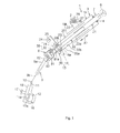
- FIG. 1 is a schematic configuration diagram of a steering system according to an embodiment of the present invention.
- a steering system 1 includes a column tube 3 that is fixed to a vehicle body-side member 2, and a column shaft 7 that is supported by the column tube 3 via a pair of bearings 4 and 5 at upper and lower sides so that the column shaft 7 is able to rotate.
- a steering member 6 such as a steering wheel is connected to an upper end of the column shaft 7.
- the steering system 1 also includes an intermediate shaft 9 that is connected to a lower end of the column shaft 7 in an axial direction X1 via a universal joint 8, a pinion shaft 11 that is connected to a lower end of the intermediate shaft 9 in the axial direction X1 via a universal joint 10, and a rack shaft 12 that serves as a steered shaft, and that has a rack 12a that meshes with a pinion 11a provided in the vicinity of an end portion of the pinion shaft 11.
- the steering system 1 is configured as an electric power steering system in which a steering assist force from an electric motor (not shown) is applied to the pinion shaft 11 or the rack shaft 12.
- a steering angle sensor 13 that detects a steering angle is arranged in a lower end of the column tube 3 in the axial direction X1 (corresponding to a later-described lower end 20L of a lower tube 20 in the axial direction X1).
- the steering angle sensor 13 includes a rotor 14 that rotates together with the column shaft 7, and a stator 15 that concentrically surrounds the rotor 14 and is fixed to the column tube 3.
- a rack and pinion mechanism which includes the pinion shaft 11 and the rack shaft 12, constitutes a steered mechanism 16.
- the rack shaft 12 is supported by a housing 18 fixed to a vehicle body-side member 17 so that the rack shaft 12 is able to move in an axial direction that extends along a right-left direction of a vehicle.
- Each end portion of the rack shaft 12 is connected to a steered wheel via a corresponding tie rod and a corresponding knuckle arm.
- the column tube 3 includes an upper tube 19 and the lower tube 20 that are fitted to each other so as to be able to slide with respect to each other in the axial direction X1.
- One of the upper tube 19 and the lower tube 20 constitutes an inner tube
- the other of the upper tube 19 and the lower tube 20 constitutes an outer tube.
- the present embodiment will be explained based on an example in which the upper tube 19 that serves as the outer tube is fitted to an outer periphery 20a of the lower tube 20 that serves as the inner tube.
- the column shaft 7 includes an upper shaft 21 and a lower shaft 22 that are fitted to each other by using splines so as to be able to slide with respect to each other in the axial direction X1 and rotate together with each other.
- One of the upper shaft 21 and the lower shaft 22 constitutes an inner shaft
- the other of the upper shaft 21 and the lower shaft 22 constitutes a tubular outer shaft.
- the present embodiment will be explained based on an example in which the upper shaft 21 that serves as the tubular outer shaft is fitted to an outer periphery 22a of the lower shaft 22 that serves as the inner shaft.
- the upper tube 19 is fixed to the vehicle body-side member 2 via an upper bracket 23.
- the lower tube 20 is fixed to a vehicle body as a lower bracket 24, which is fixed to the lower end 20L of the lower tube 20 in the axial direction X1, is fixed to a vehicle body-side member such as a cross member via a fixing bolt 25.
- the upper bracket 23 is fixed to a column bracket that is fixed to the upper tube 19.
- the upper bracket 23 is fixed to the vehicle body-side member 2 by using a stud bolt 26 that projects downward from the vehicle body-side member 2, a nut 27 that is screwed to the stud bolt 26, and a capsule 28 that is detachably held by the upper bracket 23.
- the upper bracket 23 is disconnected from the vehicle body-side member 2 due to breakage of the capsule 28, and moves together with the upper tube 19 downward in the axial direction X1.
- the intermediate shaft 9 includes an outer shaft 9a (for example, an upper shaft) and an inner shaft 9b (for example, a lower shaft) that are fitted to each other by splines so as to be able to slide with respect to each other in the axial direction.
- a lower end 22L of the lower shaft 22 in the axial direction X1 which serves as a lower end of the column shaft 7 in the axial direction X1, projects from the lower end 20L of the lower tube 20 in the axial direction X1.
- a male serration 30 is formed in the outer periphery 22a of the lower end 22L of the lower shaft 22.
- the male serration 30 includes: a first portion 31 that serves as a rotor fitting portion formed of an axial upper portion to which the rotor 14 of the steering angle sensor 13 is fitted; and a second portion 32 that serves as a yoke fitting portion formed of an axial lower portion to which the universal joint 8 (a first yoke 81 described later) is fitted.
- the rotor 14 of the steering angle sensor 13 has a serration hole 14a that is fitted to the first portion 31 of the male serration 30.
- a female serration that meshes with the first portion 31 of the male serration 30 is formed in an inner periphery of the serration hole 14a.
- a circular end wall 33 is provided in the lower end 20L of the lower tube 20 in the axial direction X1.
- the stator 15 of the steering angle sensor 13 is fixed to an outer end surface 33a of the end wall 33 by using a fixing member (not shown) such as a nail and a bolt.
- the bearing 5 at a lower side in the axial direction X1 is held by the lower tube 20, and supports the lower shaft 22 so that the lower shaft 22 is able to rotate.
- the bearing 5 includes an outer ring 51 that is fitted and fixed to an inner periphery 20b of the lower end 20L of the lower tube 20, an inner ring 52 that is fitted to the outer periphery 22a of the lower shaft 22 so that the inner ring 52 is able to rotate together with the lower shaft 22, and a plurality of rolling elements 53 that are provided between the outer ring 51 and the inner ring 52.
- An end surface of the outer ring 51 of the bearing 5 contacts an inner end surface 33b of the end wall 33 of the lower tube 20, and is thus positioned in the axial direction X1.
- the upper tube 19 moves downward in the axial direction X1.
- An impact absorbing stroke ST that is a distance of axial movement of the upper tube 19 is set within an axial area AA of the lower tube 20 between the bearing 5 and a lower end 19L of the upper tube 19 in the axial direction X1.
- the lower tube 20 includes a bearing holding portion 34 whose diameter is increased so as to hold the bearing 5, and a tapered portion 35 that is connected to an axial upper side of the bearing holding portion 34.
- the impact absorbing stroke ST corresponds to a distance between the lower end 19L of the upper tube 19 in the axial direction X1, and the tapered portion 35.
- the universal joint 8 includes the first yoke 81 that has a serration hole 81a fitted to the second portion 32 of the male serration 30 of the lower shaft 22, a second yoke 82 that is fixed to an upper end of the intermediate shaft 9 (an upper end of the outer shaft 9a), and a cross shaft 83 that connects the first yoke 81 with the second yoke 82.
- a female serration, which meshes with the second portion 32 of the male serration 30, is formed in an inner periphery of the serration hole 81a.
- the sum of a shaft length L1 of the first portion 31 for fitting the rotor 14, and a shaft length L2 of the second portion 32 for fitting the first yoke 81 corresponds to a fitting length L of the lower shaft 22 in the axial direction X1 for fitting the rotor 14 of the steering angle sensor 13 and the first yoke 81 of the universal joint 8.
- a circumferential groove 37 is provided in an intermediate portion of the second portion 32 of the male serration 30 in the axial direction X1, and a fastening bolt 36 is engaged with the circumferential groove 37 when the lower end 22L of the lower shaft 22 is fitted on the first yoke 81. As the fastening bolt 36 is engaged with the circumferential groove 37, the lower shaft 22 is retained in the serration hole 81a.
- the same male serration 30 (specifically, the first portion 31 and the second portion 32) of the column shaft 7 (the lower shaft 22) is fitted to the serration hole 14a of the rotor 14 of the steering angle sensor 13, and to the serration hole 81a of the first yoke 81 of the universal joint 8. Therefore, in the column shaft 7, it is possible to reduce the fitting length L for the steering angle sensor 13 (the rotor 14) and the universal joint 8 (the first yoke 81) in the axial direction X1.
- the bearing 5 With respect to the axial direction X1 of the column shaft 7, it is also possible to arrange the bearing 5 at a lowered position in the axial direction X1 due to the reduction of the fitting length L for the steering angle sensor 13 (the rotor 14) and the universal joint 8 (the first yoke 81). Thus, it is possible to secure the long impact absorbing stroke ST that is a distance of axial movement of the upper tube 19 with respect to the lower tube 20.
- the bearing 5 is positioned in the axial direction X1 by the end wall 33 of the lower tube 20, to which the stator 15 of the steering angle sensor 13 is fixed. Therefore, it is possible to practically dispose the bearing 5 at a lowered position in the axial direction X1, thereby practically securing the long impact absorbing stroke ST.
- the present invention is not limited to the foregoing embodiment.
- the upper tube 19 may be the inner tube
- the lower tube 20 may be the outer tube that is fitted to an outer periphery of the upper tube 19.
- the upper shaft 21 may be the inner shaft
- the lower shaft 22 may be the tubular outer shaft that is fitted to an outer periphery of the upper shaft 21.
- Various other changes may be made within the scope of the claims stated in the present invention.
Landscapes
- Engineering & Computer Science (AREA)
- Chemical & Material Sciences (AREA)
- Combustion & Propulsion (AREA)
- Transportation (AREA)
- Mechanical Engineering (AREA)
- Steering Controls (AREA)
- Power Steering Mechanism (AREA)
Applications Claiming Priority (1)
| Application Number | Priority Date | Filing Date | Title |
|---|---|---|---|
| JP2012153930A JP2014015130A (ja) | 2012-07-09 | 2012-07-09 | ステアリング装置 |
Publications (3)
| Publication Number | Publication Date |
|---|---|
| EP2684773A2 true EP2684773A2 (de) | 2014-01-15 |
| EP2684773A3 EP2684773A3 (de) | 2014-06-04 |
| EP2684773B1 EP2684773B1 (de) | 2015-09-16 |
Family
ID=48782907
Family Applications (1)
| Application Number | Title | Priority Date | Filing Date |
|---|---|---|---|
| EP13175054.9A Not-in-force EP2684773B1 (de) | 2012-07-09 | 2013-07-04 | Lenksystem |
Country Status (4)
| Country | Link |
|---|---|
| US (1) | US8899621B2 (de) |
| EP (1) | EP2684773B1 (de) |
| JP (1) | JP2014015130A (de) |
| CN (1) | CN103538624A (de) |
Families Citing this family (3)
| Publication number | Priority date | Publication date | Assignee | Title |
|---|---|---|---|---|
| CN107244348B (zh) * | 2017-05-27 | 2019-07-05 | 山东临工工程机械有限公司 | 可调节角度的转向柱机构 |
| CN109515514A (zh) * | 2018-11-27 | 2019-03-26 | 南京金龙新能源汽车研究院有限公司 | 一种电动助力转向管柱总成 |
| JP2022138729A (ja) | 2021-03-10 | 2022-09-26 | トヨタ自動車株式会社 | 運転診断装置及び運転診断方法 |
Citations (1)
| Publication number | Priority date | Publication date | Assignee | Title |
|---|---|---|---|---|
| WO2005005231A1 (ja) | 2003-07-09 | 2005-01-20 | Nsk Ltd. | ステアリング装置 |
Family Cites Families (20)
| Publication number | Priority date | Publication date | Assignee | Title |
|---|---|---|---|---|
| JPS59117911U (ja) * | 1983-01-29 | 1984-08-09 | トヨタ自動車株式会社 | 自動車のステアリングコラム |
| JPS6214308U (de) * | 1985-07-12 | 1987-01-28 | ||
| JPH02132577U (de) * | 1989-04-11 | 1990-11-02 | ||
| JP3057982B2 (ja) * | 1993-11-22 | 2000-07-04 | 株式会社豊田自動織機製作所 | リーチ型フォークリフト |
| JP2000234629A (ja) | 1999-02-15 | 2000-08-29 | Koyo Seiko Co Ltd | 軸用クランプ継手及びこれを用いたユニバーサルジョイント |
| JP2000280915A (ja) | 1999-03-31 | 2000-10-10 | Nissan Diesel Motor Co Ltd | 車両のステアリングコラム装置 |
| US6250419B1 (en) * | 2000-02-16 | 2001-06-26 | Ford Global Technologies, Inc. | Vehicle electric power assist steering system and method using H-infinity control |
| EP1541299B1 (de) | 2002-07-03 | 2008-05-14 | Nsk Ltd., | Motorservolenksystem |
| JP3842235B2 (ja) * | 2003-03-27 | 2006-11-08 | 株式会社ジェイテクト | 制御パラメータの設定方法、制御パラメータの設定装置および電気式動力舵取装置 |
| JP2005047340A (ja) * | 2003-07-31 | 2005-02-24 | Favess Co Ltd | ステアリング装置 |
| JP2005306216A (ja) * | 2004-04-21 | 2005-11-04 | Nsk Ltd | 車両用ステアリングシステム |
| JP4800082B2 (ja) * | 2006-03-31 | 2011-10-26 | 富士機工株式会社 | 車両用ステアリングコラム装置 |
| FR2908512B1 (fr) * | 2006-11-15 | 2009-02-27 | Skf Ab | Dispositif de detection de couple transmis par un arbre. |
| JP2008280002A (ja) * | 2007-05-14 | 2008-11-20 | Jtekt Corp | 衝撃吸収ステアリング装置 |
| WO2010116537A1 (ja) * | 2009-04-07 | 2010-10-14 | トヨタ自動車株式会社 | シャフト結合構造 |
| DE102009032991A1 (de) * | 2009-06-23 | 2010-12-30 | Bless, Werner M. | Lenkwellenbauteil, Lenkwelle und Herstellungsverfahren |
| CN201472452U (zh) * | 2009-08-12 | 2010-05-19 | 武汉捷隆汽车电动转向系统有限公司 | 一种带角度传感器的转向管柱 |
| WO2011065491A1 (ja) * | 2009-11-27 | 2011-06-03 | 日本精工株式会社 | 電動式パワーステアリング装置 |
| JP2012096681A (ja) * | 2010-11-02 | 2012-05-24 | Jtekt Corp | シャフトと自在継手のヨークの結合構造および電動パワーステアリング装置 |
| JP5508243B2 (ja) * | 2010-12-07 | 2014-05-28 | 株式会社ジェイテクト | 操舵伝達軸と自在継手のヨークの結合構造及び車両用操舵装置 |
-
2012
- 2012-07-09 JP JP2012153930A patent/JP2014015130A/ja active Pending
-
2013
- 2013-07-01 US US13/932,216 patent/US8899621B2/en not_active Expired - Fee Related
- 2013-07-03 CN CN201310276974.8A patent/CN103538624A/zh active Pending
- 2013-07-04 EP EP13175054.9A patent/EP2684773B1/de not_active Not-in-force
Patent Citations (1)
| Publication number | Priority date | Publication date | Assignee | Title |
|---|---|---|---|---|
| WO2005005231A1 (ja) | 2003-07-09 | 2005-01-20 | Nsk Ltd. | ステアリング装置 |
Also Published As
| Publication number | Publication date |
|---|---|
| US20140007733A1 (en) | 2014-01-09 |
| EP2684773B1 (de) | 2015-09-16 |
| JP2014015130A (ja) | 2014-01-30 |
| US8899621B2 (en) | 2014-12-02 |
| CN103538624A (zh) | 2014-01-29 |
| EP2684773A3 (de) | 2014-06-04 |
Similar Documents
| Publication | Publication Date | Title |
|---|---|---|
| EP2409894A1 (de) | Fahrzeuglenkungssystem | |
| EP2812593B1 (de) | Kreuzgelenk und joch | |
| EP2684773B1 (de) | Lenksystem | |
| US20150175198A1 (en) | Electric power steering apparatus | |
| JPWO2013153826A1 (ja) | 回転伝達機構及び電動パワーステアリング装置 | |
| EP1985521B1 (de) | Energieaufnehmendes Lenksystem | |
| US20110084470A1 (en) | Shock absorbing steering apparatus | |
| US20200062291A1 (en) | Shaft for steering device, method of manufacturing shaft for steering device, and electric power steering device | |
| JP2013010373A (ja) | 車両用操舵装置 | |
| KR102869189B1 (ko) | 차량의 조향장치 | |
| JP5130915B2 (ja) | 電動パワーステアリング装置 | |
| KR102750656B1 (ko) | 차량의 조향장치 | |
| EP3081458B1 (de) | Elektrische servolenkvorrichtung und verfahren zur montage | |
| JP2012112416A (ja) | 伸縮可能シャフトおよび車両用操舵装置 | |
| JP2017140976A (ja) | ステアリングコラム装置 | |
| JP2012117560A (ja) | 伸縮可能シャフトおよびその製造方法並びに車両用操舵装置 | |
| EP2783942A1 (de) | Lenkvorrichtung | |
| KR102843452B1 (ko) | 스티어 바이 와이어식 조향장치 | |
| JP5370201B2 (ja) | 自在継手のヨ−ク | |
| JP2008087583A (ja) | ステアリング装置及びステアリング装置の組立方法 | |
| JP2006001423A (ja) | 車両用ステアリング装置及びその組立方法 | |
| JP2008056144A (ja) | コラム式電動パワーステアリング装置 | |
| JP5556754B2 (ja) | 電動パワーステアリング装置 | |
| JP4620478B2 (ja) | 不整地走行用車両の電動舵取補助装置の操舵軸支持構造 | |
| JP7003836B2 (ja) | 緩衝ジョイント及びステアリング装置 |
Legal Events
| Date | Code | Title | Description |
|---|---|---|---|
| PUAI | Public reference made under article 153(3) epc to a published international application that has entered the european phase |
Free format text: ORIGINAL CODE: 0009012 |
|
| AK | Designated contracting states |
Kind code of ref document: A2 Designated state(s): AL AT BE BG CH CY CZ DE DK EE ES FI FR GB GR HR HU IE IS IT LI LT LU LV MC MK MT NL NO PL PT RO RS SE SI SK SM TR |
|
| AX | Request for extension of the european patent |
Extension state: BA ME |
|
| PUAL | Search report despatched |
Free format text: ORIGINAL CODE: 0009013 |
|
| AK | Designated contracting states |
Kind code of ref document: A3 Designated state(s): AL AT BE BG CH CY CZ DE DK EE ES FI FR GB GR HR HU IE IS IT LI LT LU LV MC MK MT NL NO PL PT RO RS SE SI SK SM TR |
|
| AX | Request for extension of the european patent |
Extension state: BA ME |
|
| RIC1 | Information provided on ipc code assigned before grant |
Ipc: B62D 15/02 20060101AFI20140425BHEP Ipc: B62D 1/16 20060101ALI20140425BHEP |
|
| 17P | Request for examination filed |
Effective date: 20141029 |
|
| RBV | Designated contracting states (corrected) |
Designated state(s): AL AT BE BG CH CY CZ DE DK EE ES FI FR GB GR HR HU IE IS IT LI LT LU LV MC MK MT NL NO PL PT RO RS SE SI SK SM TR |
|
| GRAP | Despatch of communication of intention to grant a patent |
Free format text: ORIGINAL CODE: EPIDOSNIGR1 |
|
| INTG | Intention to grant announced |
Effective date: 20150318 |
|
| GRAS | Grant fee paid |
Free format text: ORIGINAL CODE: EPIDOSNIGR3 |
|
| GRAA | (expected) grant |
Free format text: ORIGINAL CODE: 0009210 |
|
| RIN1 | Information on inventor provided before grant (corrected) |
Inventor name: RIKITAKE, YOSHIKAZU Inventor name: TANAKA, EIJI |
|
| AK | Designated contracting states |
Kind code of ref document: B1 Designated state(s): AL AT BE BG CH CY CZ DE DK EE ES FI FR GB GR HR HU IE IS IT LI LT LU LV MC MK MT NL NO PL PT RO RS SE SI SK SM TR |
|
| REG | Reference to a national code |
Ref country code: GB Ref legal event code: FG4D |
|
| REG | Reference to a national code |
Ref country code: CH Ref legal event code: EP |
|
| REG | Reference to a national code |
Ref country code: IE Ref legal event code: FG4D |
|
| REG | Reference to a national code |
Ref country code: AT Ref legal event code: REF Ref document number: 749562 Country of ref document: AT Kind code of ref document: T Effective date: 20151015 |
|
| REG | Reference to a national code |
Ref country code: DE Ref legal event code: R096 Ref document number: 602013003041 Country of ref document: DE |
|
| REG | Reference to a national code |
Ref country code: NL Ref legal event code: MP Effective date: 20150916 |
|
| PG25 | Lapsed in a contracting state [announced via postgrant information from national office to epo] |
Ref country code: LV Free format text: LAPSE BECAUSE OF FAILURE TO SUBMIT A TRANSLATION OF THE DESCRIPTION OR TO PAY THE FEE WITHIN THE PRESCRIBED TIME-LIMIT Effective date: 20150916 Ref country code: LT Free format text: LAPSE BECAUSE OF FAILURE TO SUBMIT A TRANSLATION OF THE DESCRIPTION OR TO PAY THE FEE WITHIN THE PRESCRIBED TIME-LIMIT Effective date: 20150916 Ref country code: NO Free format text: LAPSE BECAUSE OF FAILURE TO SUBMIT A TRANSLATION OF THE DESCRIPTION OR TO PAY THE FEE WITHIN THE PRESCRIBED TIME-LIMIT Effective date: 20151216 Ref country code: FI Free format text: LAPSE BECAUSE OF FAILURE TO SUBMIT A TRANSLATION OF THE DESCRIPTION OR TO PAY THE FEE WITHIN THE PRESCRIBED TIME-LIMIT Effective date: 20150916 Ref country code: GR Free format text: LAPSE BECAUSE OF FAILURE TO SUBMIT A TRANSLATION OF THE DESCRIPTION OR TO PAY THE FEE WITHIN THE PRESCRIBED TIME-LIMIT Effective date: 20151217 |
|
| REG | Reference to a national code |
Ref country code: LT Ref legal event code: MG4D |
|
| REG | Reference to a national code |
Ref country code: AT Ref legal event code: MK05 Ref document number: 749562 Country of ref document: AT Kind code of ref document: T Effective date: 20150916 |
|
| PG25 | Lapsed in a contracting state [announced via postgrant information from national office to epo] |
Ref country code: HR Free format text: LAPSE BECAUSE OF FAILURE TO SUBMIT A TRANSLATION OF THE DESCRIPTION OR TO PAY THE FEE WITHIN THE PRESCRIBED TIME-LIMIT Effective date: 20150916 Ref country code: RS Free format text: LAPSE BECAUSE OF FAILURE TO SUBMIT A TRANSLATION OF THE DESCRIPTION OR TO PAY THE FEE WITHIN THE PRESCRIBED TIME-LIMIT Effective date: 20150916 Ref country code: SE Free format text: LAPSE BECAUSE OF FAILURE TO SUBMIT A TRANSLATION OF THE DESCRIPTION OR TO PAY THE FEE WITHIN THE PRESCRIBED TIME-LIMIT Effective date: 20150916 |
|
| PG25 | Lapsed in a contracting state [announced via postgrant information from national office to epo] |
Ref country code: NL Free format text: LAPSE BECAUSE OF FAILURE TO SUBMIT A TRANSLATION OF THE DESCRIPTION OR TO PAY THE FEE WITHIN THE PRESCRIBED TIME-LIMIT Effective date: 20150916 |
|
| PG25 | Lapsed in a contracting state [announced via postgrant information from national office to epo] |
Ref country code: IS Free format text: LAPSE BECAUSE OF FAILURE TO SUBMIT A TRANSLATION OF THE DESCRIPTION OR TO PAY THE FEE WITHIN THE PRESCRIBED TIME-LIMIT Effective date: 20160116 Ref country code: CZ Free format text: LAPSE BECAUSE OF FAILURE TO SUBMIT A TRANSLATION OF THE DESCRIPTION OR TO PAY THE FEE WITHIN THE PRESCRIBED TIME-LIMIT Effective date: 20150916 Ref country code: IT Free format text: LAPSE BECAUSE OF FAILURE TO SUBMIT A TRANSLATION OF THE DESCRIPTION OR TO PAY THE FEE WITHIN THE PRESCRIBED TIME-LIMIT Effective date: 20150916 Ref country code: EE Free format text: LAPSE BECAUSE OF FAILURE TO SUBMIT A TRANSLATION OF THE DESCRIPTION OR TO PAY THE FEE WITHIN THE PRESCRIBED TIME-LIMIT Effective date: 20150916 Ref country code: ES Free format text: LAPSE BECAUSE OF FAILURE TO SUBMIT A TRANSLATION OF THE DESCRIPTION OR TO PAY THE FEE WITHIN THE PRESCRIBED TIME-LIMIT Effective date: 20150916 Ref country code: SK Free format text: LAPSE BECAUSE OF FAILURE TO SUBMIT A TRANSLATION OF THE DESCRIPTION OR TO PAY THE FEE WITHIN THE PRESCRIBED TIME-LIMIT Effective date: 20150916 |
|
| PG25 | Lapsed in a contracting state [announced via postgrant information from national office to epo] |
Ref country code: AT Free format text: LAPSE BECAUSE OF FAILURE TO SUBMIT A TRANSLATION OF THE DESCRIPTION OR TO PAY THE FEE WITHIN THE PRESCRIBED TIME-LIMIT Effective date: 20150916 Ref country code: PT Free format text: LAPSE BECAUSE OF FAILURE TO SUBMIT A TRANSLATION OF THE DESCRIPTION OR TO PAY THE FEE WITHIN THE PRESCRIBED TIME-LIMIT Effective date: 20160118 Ref country code: RO Free format text: LAPSE BECAUSE OF FAILURE TO SUBMIT A TRANSLATION OF THE DESCRIPTION OR TO PAY THE FEE WITHIN THE PRESCRIBED TIME-LIMIT Effective date: 20150916 Ref country code: PL Free format text: LAPSE BECAUSE OF FAILURE TO SUBMIT A TRANSLATION OF THE DESCRIPTION OR TO PAY THE FEE WITHIN THE PRESCRIBED TIME-LIMIT Effective date: 20150916 |
|
| REG | Reference to a national code |
Ref country code: FR Ref legal event code: PLFP Year of fee payment: 4 |
|
| REG | Reference to a national code |
Ref country code: DE Ref legal event code: R097 Ref document number: 602013003041 Country of ref document: DE |
|
| PLBE | No opposition filed within time limit |
Free format text: ORIGINAL CODE: 0009261 |
|
| STAA | Information on the status of an ep patent application or granted ep patent |
Free format text: STATUS: NO OPPOSITION FILED WITHIN TIME LIMIT |
|
| 26N | No opposition filed |
Effective date: 20160617 |
|
| PG25 | Lapsed in a contracting state [announced via postgrant information from national office to epo] |
Ref country code: DK Free format text: LAPSE BECAUSE OF FAILURE TO SUBMIT A TRANSLATION OF THE DESCRIPTION OR TO PAY THE FEE WITHIN THE PRESCRIBED TIME-LIMIT Effective date: 20150916 |
|
| PGFP | Annual fee paid to national office [announced via postgrant information from national office to epo] |
Ref country code: FR Payment date: 20160613 Year of fee payment: 4 |
|
| PG25 | Lapsed in a contracting state [announced via postgrant information from national office to epo] |
Ref country code: SI Free format text: LAPSE BECAUSE OF FAILURE TO SUBMIT A TRANSLATION OF THE DESCRIPTION OR TO PAY THE FEE WITHIN THE PRESCRIBED TIME-LIMIT Effective date: 20150916 |
|
| PG25 | Lapsed in a contracting state [announced via postgrant information from national office to epo] |
Ref country code: BE Free format text: LAPSE BECAUSE OF FAILURE TO SUBMIT A TRANSLATION OF THE DESCRIPTION OR TO PAY THE FEE WITHIN THE PRESCRIBED TIME-LIMIT Effective date: 20150916 |
|
| REG | Reference to a national code |
Ref country code: DE Ref legal event code: R119 Ref document number: 602013003041 Country of ref document: DE |
|
| REG | Reference to a national code |
Ref country code: CH Ref legal event code: PL |
|
| PG25 | Lapsed in a contracting state [announced via postgrant information from national office to epo] |
Ref country code: MC Free format text: LAPSE BECAUSE OF FAILURE TO SUBMIT A TRANSLATION OF THE DESCRIPTION OR TO PAY THE FEE WITHIN THE PRESCRIBED TIME-LIMIT Effective date: 20150916 |
|
| PG25 | Lapsed in a contracting state [announced via postgrant information from national office to epo] |
Ref country code: CH Free format text: LAPSE BECAUSE OF NON-PAYMENT OF DUE FEES Effective date: 20160731 Ref country code: DE Free format text: LAPSE BECAUSE OF NON-PAYMENT OF DUE FEES Effective date: 20170201 Ref country code: LI Free format text: LAPSE BECAUSE OF NON-PAYMENT OF DUE FEES Effective date: 20160731 |
|
| REG | Reference to a national code |
Ref country code: IE Ref legal event code: MM4A |
|
| PG25 | Lapsed in a contracting state [announced via postgrant information from national office to epo] |
Ref country code: IE Free format text: LAPSE BECAUSE OF NON-PAYMENT OF DUE FEES Effective date: 20160704 |
|
| PG25 | Lapsed in a contracting state [announced via postgrant information from national office to epo] |
Ref country code: LU Free format text: LAPSE BECAUSE OF NON-PAYMENT OF DUE FEES Effective date: 20160704 |
|
| GBPC | Gb: european patent ceased through non-payment of renewal fee |
Effective date: 20170704 |
|
| REG | Reference to a national code |
Ref country code: FR Ref legal event code: ST Effective date: 20180330 |
|
| PG25 | Lapsed in a contracting state [announced via postgrant information from national office to epo] |
Ref country code: GB Free format text: LAPSE BECAUSE OF NON-PAYMENT OF DUE FEES Effective date: 20170704 |
|
| PG25 | Lapsed in a contracting state [announced via postgrant information from national office to epo] |
Ref country code: FR Free format text: LAPSE BECAUSE OF NON-PAYMENT OF DUE FEES Effective date: 20170731 Ref country code: SM Free format text: LAPSE BECAUSE OF FAILURE TO SUBMIT A TRANSLATION OF THE DESCRIPTION OR TO PAY THE FEE WITHIN THE PRESCRIBED TIME-LIMIT Effective date: 20150916 Ref country code: CY Free format text: LAPSE BECAUSE OF FAILURE TO SUBMIT A TRANSLATION OF THE DESCRIPTION OR TO PAY THE FEE WITHIN THE PRESCRIBED TIME-LIMIT Effective date: 20150916 Ref country code: HU Free format text: LAPSE BECAUSE OF FAILURE TO SUBMIT A TRANSLATION OF THE DESCRIPTION OR TO PAY THE FEE WITHIN THE PRESCRIBED TIME-LIMIT; INVALID AB INITIO Effective date: 20130704 |
|
| PG25 | Lapsed in a contracting state [announced via postgrant information from national office to epo] |
Ref country code: MK Free format text: LAPSE BECAUSE OF FAILURE TO SUBMIT A TRANSLATION OF THE DESCRIPTION OR TO PAY THE FEE WITHIN THE PRESCRIBED TIME-LIMIT Effective date: 20150916 Ref country code: TR Free format text: LAPSE BECAUSE OF FAILURE TO SUBMIT A TRANSLATION OF THE DESCRIPTION OR TO PAY THE FEE WITHIN THE PRESCRIBED TIME-LIMIT Effective date: 20150916 Ref country code: MT Free format text: LAPSE BECAUSE OF NON-PAYMENT OF DUE FEES Effective date: 20160731 |
|
| PG25 | Lapsed in a contracting state [announced via postgrant information from national office to epo] |
Ref country code: BG Free format text: LAPSE BECAUSE OF FAILURE TO SUBMIT A TRANSLATION OF THE DESCRIPTION OR TO PAY THE FEE WITHIN THE PRESCRIBED TIME-LIMIT Effective date: 20150916 |
|
| PG25 | Lapsed in a contracting state [announced via postgrant information from national office to epo] |
Ref country code: AL Free format text: LAPSE BECAUSE OF FAILURE TO SUBMIT A TRANSLATION OF THE DESCRIPTION OR TO PAY THE FEE WITHIN THE PRESCRIBED TIME-LIMIT Effective date: 20150916 |