EP2685040A2 - Composant précontraint et procédé de fonctionnement pour une fenêtre ou une porte-fenêtre - Google Patents
Composant précontraint et procédé de fonctionnement pour une fenêtre ou une porte-fenêtre Download PDFInfo
- Publication number
- EP2685040A2 EP2685040A2 EP13176007.6A EP13176007A EP2685040A2 EP 2685040 A2 EP2685040 A2 EP 2685040A2 EP 13176007 A EP13176007 A EP 13176007A EP 2685040 A2 EP2685040 A2 EP 2685040A2
- Authority
- EP
- European Patent Office
- Prior art keywords
- wing
- biasing member
- frame
- power transmission
- arm
- Prior art date
- Legal status (The legal status is an assumption and is not a legal conclusion. Google has not performed a legal analysis and makes no representation as to the accuracy of the status listed.)
- Granted
Links
Images

Classifications
-
- E—FIXED CONSTRUCTIONS
- E05—LOCKS; KEYS; WINDOW OR DOOR FITTINGS; SAFES
- E05D—HINGES OR SUSPENSION DEVICES FOR DOORS, WINDOWS OR WINGS
- E05D15/00—Suspension arrangements for wings
- E05D15/06—Suspension arrangements for wings for wings sliding horizontally more or less in their own plane
- E05D15/10—Suspension arrangements for wings for wings sliding horizontally more or less in their own plane movable out of one plane into a second parallel plane
- E05D15/1005—Suspension arrangements for wings for wings sliding horizontally more or less in their own plane movable out of one plane into a second parallel plane the wing being supported on arms movable in horizontal planes
- E05D15/1013—Suspension arrangements for wings for wings sliding horizontally more or less in their own plane movable out of one plane into a second parallel plane the wing being supported on arms movable in horizontal planes specially adapted for windows
-
- E—FIXED CONSTRUCTIONS
- E05—LOCKS; KEYS; WINDOW OR DOOR FITTINGS; SAFES
- E05Y—INDEXING SCHEME ASSOCIATED WITH SUBCLASSES E05D AND E05F, RELATING TO CONSTRUCTION ELEMENTS, ELECTRIC CONTROL, POWER SUPPLY, POWER SIGNAL OR TRANSMISSION, USER INTERFACES, MOUNTING OR COUPLING, DETAILS, ACCESSORIES, AUXILIARY OPERATIONS NOT OTHERWISE PROVIDED FOR, APPLICATION THEREOF
- E05Y2201/00—Constructional elements; Accessories therefor
- E05Y2201/40—Motors; Magnets; Springs; Weights; Accessories therefor
- E05Y2201/404—Function thereof
- E05Y2201/422—Function thereof for opening
- E05Y2201/426—Function thereof for opening for the initial opening movement
-
- E—FIXED CONSTRUCTIONS
- E05—LOCKS; KEYS; WINDOW OR DOOR FITTINGS; SAFES
- E05Y—INDEXING SCHEME ASSOCIATED WITH SUBCLASSES E05D AND E05F, RELATING TO CONSTRUCTION ELEMENTS, ELECTRIC CONTROL, POWER SUPPLY, POWER SIGNAL OR TRANSMISSION, USER INTERFACES, MOUNTING OR COUPLING, DETAILS, ACCESSORIES, AUXILIARY OPERATIONS NOT OTHERWISE PROVIDED FOR, APPLICATION THEREOF
- E05Y2201/00—Constructional elements; Accessories therefor
- E05Y2201/40—Motors; Magnets; Springs; Weights; Accessories therefor
- E05Y2201/47—Springs
-
- E—FIXED CONSTRUCTIONS
- E05—LOCKS; KEYS; WINDOW OR DOOR FITTINGS; SAFES
- E05Y—INDEXING SCHEME ASSOCIATED WITH SUBCLASSES E05D AND E05F, RELATING TO CONSTRUCTION ELEMENTS, ELECTRIC CONTROL, POWER SUPPLY, POWER SIGNAL OR TRANSMISSION, USER INTERFACES, MOUNTING OR COUPLING, DETAILS, ACCESSORIES, AUXILIARY OPERATIONS NOT OTHERWISE PROVIDED FOR, APPLICATION THEREOF
- E05Y2900/00—Application of doors, windows, wings or fittings thereof
- E05Y2900/10—Application of doors, windows, wings or fittings thereof for buildings or parts thereof
- E05Y2900/13—Type of wing
- E05Y2900/132—Doors
-
- E—FIXED CONSTRUCTIONS
- E05—LOCKS; KEYS; WINDOW OR DOOR FITTINGS; SAFES
- E05Y—INDEXING SCHEME ASSOCIATED WITH SUBCLASSES E05D AND E05F, RELATING TO CONSTRUCTION ELEMENTS, ELECTRIC CONTROL, POWER SUPPLY, POWER SIGNAL OR TRANSMISSION, USER INTERFACES, MOUNTING OR COUPLING, DETAILS, ACCESSORIES, AUXILIARY OPERATIONS NOT OTHERWISE PROVIDED FOR, APPLICATION THEREOF
- E05Y2900/00—Application of doors, windows, wings or fittings thereof
- E05Y2900/10—Application of doors, windows, wings or fittings thereof for buildings or parts thereof
- E05Y2900/13—Type of wing
- E05Y2900/148—Windows
Definitions
- the disclosed and claimed invention relates generally to a window or patio door which includes at least one wing which can be opened by means of an actuator so as to provide an opening gap between the wing and a frame of the window or the French window. This as a method and as a device.
- An object of the invention is to improve the ease of use for a window and / or door with a view to opening a sash and maintaining an open position of the sash.
- a biasing member includes a first power transmission component engageable with a wing of the window and / or the door.
- the biasing member further comprises a second, with a frame of the window and / or the door brought into contact power transmission component (claim 1).
- the biasing member is provided with mechanically biased biasing means coupled to the first power transmission component and the second power transmission component and configured to cause a force acting in the direction of increasing an opening gap between the blade and the frame. This at least up to a predetermined width of the opening gap, which is predetermined by scissors of the fitting (claim 19).
- the biasing member according to the invention is thus designed so that due to the mechanically operated biasing means, a force is exerted which tends to support the opening of the wing.
- a substantial proportion of the force required for this purpose can be provided by the mechanically operated pretensioning device, resulting in a significantly lower expenditure of force on the part of the operator or an automatic opening system.
- the mechanically operated biasing device is a device in which energy that is released during an opening process due to the force acting, was stored by mechanical action on the biasing device when closing.
- no electrical drive components are required in order to provide the desired preload force when opening a wing of the window or the door.
- the biasing device is further formed to counteract this reduction in reducing the opening gap.
- this reduction in this way, a more stable position of the wing is ensured in the presence of an opening gap.
- there is no undesirable high resistance in closing the wing since typically the largest force of the biasing member occurring at the end of a closing operation is substantially substantially compensated by the previously received pulse of the often heavy blade.
- the first power transmission component comprises a first arm and the second power transmission component comprises a second arm of a scissors arrangement.
- the use of a scissors arrangement results in a very compact construction for the biasing member, since the individual arms of the scissor assembly can be provided as elongated components with a small thickness, so that attachment to the wing or the frame in conventional constructions is possible without major additional design measures.
- the arms of the scissor assembly can be of the same or different lengths, so that can be achieved without great effort to adapt to the existing conditions in the basic construction of windows and doors.
- the opening gap between the wing and the frame can thus be varied by generating and adjusting an opening angle of the scissor assembly, the two arms efficiently serving for power transmission.
- the arms can thus act at least as part of the first and second components for power transmission, wherein, if necessary, further mechanical components can be provided to actually contact the wing and / or the frame.
- the first arm and the second arm each have a first end region with a common axis of rotation formed therein.
- the entire length of the first and the second arm can be used to produce the largest possible opening gap at a predetermined opening angle between the first arm and the second arm.
- the corresponding axis of rotation can also be provided in a middle region of the arms.
- the first arm and / or the second arm are provided with a holding device, which ensures a permanent contact with the wing or the frame.
- the holding device is advantageously designed so that an assembly at a suitable position on the frame or on the wing is possible.
- suitable fastening means are provided which allow mounting on existing fitting components.
- the second end region of the first or the second arm is provided with a receptacle for attachment to a movement rail, in particular as a slide rail.
- a movement rail in particular as a slide rail.
- the pretensioning component is designed in the form of a fitting component of the sash of the window and / or the door and thus allows a space-saving installation at a suitable position of the sash or of the frame.
- the structure of the biasing member according to the invention in the form of a fitting component can be made so that integration into existing hardware components is possible, with no or only very minor structural changes in the design of existing types of construction of windows and doors are made.
- the biasing means comprises a spring element.
- Suitable components such as in the form of a leg spring, a tension spring, a compression spring and the like can be used, so that an efficient adaptation of the force-generating component in the pretensioner can be made depending on the structural requirements.
- the pretensioning device has a compressed gas volume, which is provided, for example, in the form of a shock absorber and the like. In this way, a desired adaptation to the structural requirements can be achieved efficiently, since a large number of corresponding gas springs is available.
- a spring element is provided and this is mounted in the direction of the axis of rotation of the scissor assembly in a space which is formed between the first arm and the second arm.
- the spring element is provided in the form of a leg spring, which is fastened to the first and the second arm with suitable fastening means.
- the wire guide the leg spring takes place in advantageous embodiments so that at an opening angle of zero, the maximum biasing force results, so that in particular the otherwise force-demanding opening operation in the Initial phase a strong supporting force effect is provided by the biasing member.
- a height of the biasing member is not greater than the height of a space between a sash and a compassionfalz or the height between an overlying frame-side guide rail (or receptacle) and a wing retaining rail (or recording) takes on the biasing member (claim 11).
- the biasing member without additional structural measures in windows and doors with otherwise known properties and dimensions integrate (and cover).
- a window and / or door device which comprises a frame and a wing with an actuator provided for opening the sash. Furthermore, a pretensioning component is provided in the window and / or door device according to the invention, as described above or also below, which develops a force effect between the frame and the wing.
- the biasing member is mounted in a variant on an upper portion of the frame or the wing.
- the biasing member is mounted to a vertical portion of the frame or wing. That is, the biasing member of the present invention can be disposed at an appropriate position on the vertical or horizontal portions so as to achieve efficient power development without requiring changes in the basic structure of the window and / or door apparatus.
- the biasing member is mounted in a space between the wing and frame.
- a pretensioning component advantageously in the form of a fitting component, which delivers an additional force to support the wing opening movement and, in the open state of the wing, assists this position by means of a pre-existing prestressing element.
- the closing forces on the wing, the fitting or the actuator do not increase or only slightly.
- the assembly of this component takes place in the form of an additional component, so that the respective standard fitting for the different window opening types is further used.
- the formation of the scissor arms can be designed so that a variety of connections to the wing / frame are possible.
- the possibility of inserting a scissor arm in a wing holding rail and the design of the second scissor arm, in the way that a movable piece, in particular coupled as a slider can be plugged opens the possibility that the scissor assembly can be moved laterally with the wing , In this way, a known and common operation of the parallel parking (tilt) sliding door much easier.
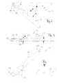
- FIG. 1 shows a perspective view of a window device 100, the frame 1 and at least one wing 2, which is movable with respect to the frame 1, has.
- the device 100 has an actuating device 3 (as a lever), by means of which a locking or unlocking of the wing 2 can take place in the closed position and can then be brought by a force of the wing 2 from a closed position to an open position, wherein an opening gap 2a between the frame 1 and the wing 2 results.
- actuating device 3 as a lever
- the window device 100 is a hinged window with parallel sliding wing 2, while in other embodiments also tilt windows, folding windows and the like are used.
- the device 100 is also referred to as a Door device or provided as a French door, since the biasing member 10 can be applied to a variety of different types of window devices and door devices.
- FIG. 1 the wing 2 is shown in an open position, in which by means of known fitting components 6, a mechanical guidance of the wing with respect to the frame 1 takes place.
- a biasing member 10 is provided which is formed so that one for reaching the in FIG. 1 shown opening gap 2a a force F is exerted during the opening operation. Further, the biasing member 10 further exerts a counteracting the reduction of the opening gap 2a force, also referred to as F from. This results in a more stable definition of the opening gap 2a and it is an undesirable change of the opening gap 2a toward the closed position in the absence of action of an operator substantially avoided.
- the biasing member 10 is provided in the form of a scissor assembly, in which a biasing means, which is described in detail below, is provided in the form of a spring or as a pneumatic-hydraulic component or the like, which the desired for the opening operation power assistance F provides.
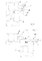
- FIG. 2 shows a plan view of the biasing member 10, which has a first arm 15 and a second arm 16 as a scissor assembly, which are connected to each other at respective end portions 15a, 16a by a common axis of rotation 14.
- the biasing member 10 further includes a biasing means 18, which is provided in the illustrated embodiment as a leg spring.
- the biasing device 18 is designed so that at least up to a certain opening angle ⁇ , the force F between the two arms 16 and 15 acts, which leads to an increase in the opening angle. Providing a spring for the biasing device 18 thus results in a force which is dependent on the size of the opening angle ⁇ and in the illustrated embodiment is greatest at an opening angle of zero.
- the arms 15, 16 are provided with different lengths, while in other embodiments they may be provided with the same length.
- the arms 15, 16 preferably have the dimensions of commonly used cover rail material, similar to steel strip, although other design variants depending on the available space are possible.
- FIG. 3 is a side view of the biasing member 10 and FIG. 4 a view from below.
- a height H which in turn is selected so that the biasing member 10 can be integrated in a desired manner in a window device or door device, without causing undesirable additional design measures to an existing structure are required.
- the scissor arms are thus spaced apart from each other, to receive in this intermediate space of the height Z, the biasing means in the form of a spring element, which is formed in this embodiment as a leg spring about the axis of rotation 14.
- a spring leg 18a is associated with the arm 15 and positively connected thereto, while a second spring leg 18b associated with the arm 16 and connected thereto, wherein this is done with suitable fasteners. Exemplary is in to FIG. 4 a fastener 19a is shown on the arm 16. Both connections result in a pair of scissors with internal leg spring.
- the opening angle ⁇ is only as large as the max. Opening angle of the relaxed spring allows. In this state, the biasing member 10 has no bias.
- the Drehachsseite 14 At the end portion 15a of the first arm 15 is the Drehachsseite 14 and at an opposite end portion 15b is a holding device as Fasteners 17 ( FIG. 3 ), z. B. in the form of a projecting receptacle, for example as riveted bolt, which can be inserted into a slider or wing frame.
- the second arm 16 is formed with its one pivot axis end 16a and with another end portion 16b so that receiving holes 16c are provided for fastening means 19b, such as clamping bolts, screws, which act as a clamping device when the arm 16 is dimensioned, that it can be inserted into an existing wing retaining rail and secured against displacement.
- fastening means 19b such as clamping bolts, screws
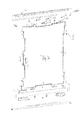
- FIG. 5 shows a side cross-sectional view in which the frame 1 and the wing 2 are in a closed position.
- the arm 16 is fastened by means of the fastening means 19b in a retaining rail 2b of the wing 2 and is thus in permanent contact with the wing 2.
- the arm 15 of the biasing member 10 is connected via the holding device 17 with a moving element as, for example, slider 20, which in turn is guided in a rail 1a on the frame 1.
- the biasing means 18 causes maximum force between the wing 2 and the frame 1 to assist or initiate an unlocking operation.
- FIG. 6 shows the frame 1 and the wing 2 in an open position, in which thus the arm 15 and the arm 16 include a non-zero opening angle with each other, as for example in the FIGS. 2 and 4 is shown.
- the biasing force 18 force F acts during the transition from the closed state to the open state caused by the biasing force 18 force F, which tends to increase the opening angle ⁇ further, unless the maximum opening angle is reached 2a, in which the biasing means 18 no further Pretension force exerts (and the scissors 6b limit this opening 2a a).
- the height H of the biasing member 10 - which is here essentially defined by the two arms 15 and 16 and the intermediate biasing device 18 - dimensioned so that it is not greater than the space BR (its height) between the wing. 2 (Top edge) and frame 1 (lower edge of slide rail 1a); the space under an overlying frame-side guide rail (or recording 1a) and the wing-holding rail 2b (its mounting point or its horizontal portion of the angle 2b). This is usually the top of the wing on which the angled support rail 2b is mounted.
- FIG. 7 is an exploded perspective view illustrating conventional standard fitting components, collectively designated 6, while the biasing member 10 is integrated at an upper position in cooperation with the standard fitting components 6 so that there are no additional design measures with respect to the otherwise predetermined one Structure of the window or the door are required.
- sliding members 6c of the standard fitting members 6 are shown together with corresponding standard opening shears 6b, which allow the generation of an opening gap 2a and a displacement of the wing, but high forces of the operator would be required.
- the biasing member 10 is disposed between the two Ausstellscheren 6b.
- a scissors assembly 10 is additionally provided, which provides the desired, biasing force F during the opening operation and also maintains a biasing force in the open position.
- biasing device 18 shown in the figures as a spring of the biasing member 10 is only an advantageous variant.
- biasing member 10 is placed outboard at the top of the frame / wing in a preferred embodiment, another positioning, e.g. B. on the side of / on the vertical profiles possible.
- Another possible mounting space can also be the distance br1 between the frame and sash (in the rebate), shown in FIG. 5 but without prestressing scissors 10 inserted there.
Landscapes
- Engineering & Computer Science (AREA)
- Mechanical Engineering (AREA)
- Wing Frames And Configurations (AREA)
- Window Of Vehicle (AREA)
- Closing And Opening Devices For Wings, And Checks For Wings (AREA)
- Power-Operated Mechanisms For Wings (AREA)
Priority Applications (1)
| Application Number | Priority Date | Filing Date | Title |
|---|---|---|---|
| PL13176007T PL2685040T3 (pl) | 2012-07-10 | 2013-07-10 | Element naprężający i sposób eksploatacji dla okna lub drzwi okiennych |
Applications Claiming Priority (1)
| Application Number | Priority Date | Filing Date | Title |
|---|---|---|---|
| DE102012106191.2A DE102012106191B4 (de) | 2012-07-10 | 2012-07-10 | Vorspannbauteil für eine Fenster- oder Türvorrichtung und Fenster- oder Türvorrichtung |
Publications (3)
| Publication Number | Publication Date |
|---|---|
| EP2685040A2 true EP2685040A2 (fr) | 2014-01-15 |
| EP2685040A3 EP2685040A3 (fr) | 2018-01-17 |
| EP2685040B1 EP2685040B1 (fr) | 2021-10-06 |
Family
ID=48782999
Family Applications (1)
| Application Number | Title | Priority Date | Filing Date |
|---|---|---|---|
| EP13176007.6A Active EP2685040B1 (fr) | 2012-07-10 | 2013-07-10 | Composant précontraint et procédé de fonctionnement pour une fenêtre ou une porte-fenêtre |
Country Status (3)
| Country | Link |
|---|---|
| EP (1) | EP2685040B1 (fr) |
| DE (1) | DE102012106191B4 (fr) |
| PL (1) | PL2685040T3 (fr) |
Families Citing this family (1)
| Publication number | Priority date | Publication date | Assignee | Title |
|---|---|---|---|---|
| DE102018201994B4 (de) * | 2018-02-08 | 2020-10-01 | Roto Frank Ag | Unterstützungsbeschlag für einen kippbaren Flügel eines Fensters oder einer Tür |
Family Cites Families (6)
| Publication number | Priority date | Publication date | Assignee | Title |
|---|---|---|---|---|
| DE549635C (de) * | 1928-01-24 | 1932-04-29 | Wilhelm Hautau | Aufdrueckschere fuer Oberlichtfenster mit starren Scherenarmen und einer um das Scherengelenk gelegten Aufdrueckfeder |
| DE3234677C2 (de) * | 1982-09-18 | 1986-10-23 | Gretsch-Unitas GmbH Baubeschläge, 7257 Ditzingen | Beschlag für einen zumindest parallelabstellbaren Flügel eines Fensters, einer Tür od. dgl. |
| JPS63206584A (ja) * | 1987-02-20 | 1988-08-25 | 株式会社三協精機製作所 | ドアクロ−ザ− |
| FR2762867B1 (fr) * | 1997-04-30 | 1999-07-09 | Ecodis Sa | Dispositif d'articulation d'une coupole sur une costiere d'un lanterneau |
| CH699371B1 (de) * | 2005-04-22 | 2010-02-26 | Eku Ag | Mitnehmer für eine Endlageeinzugs- und Endlagedämpfungsvorrichtung und eine Endlageeinzugs- und Endlagedämpfungsvorrichtung für eine Schiebetür. |
| EP2050908A1 (fr) * | 2007-10-16 | 2009-04-22 | Jeld Wen Türen GmbH | Mécanisme integré |
-
2012
- 2012-07-10 DE DE102012106191.2A patent/DE102012106191B4/de not_active Expired - Fee Related
-
2013
- 2013-07-10 PL PL13176007T patent/PL2685040T3/pl unknown
- 2013-07-10 EP EP13176007.6A patent/EP2685040B1/fr active Active
Non-Patent Citations (1)
| Title |
|---|
| None |
Also Published As
| Publication number | Publication date |
|---|---|
| PL2685040T3 (pl) | 2022-01-24 |
| EP2685040A3 (fr) | 2018-01-17 |
| EP2685040B1 (fr) | 2021-10-06 |
| DE102012106191B4 (de) | 2014-12-24 |
| DE102012106191A1 (de) | 2014-01-16 |
Similar Documents
| Publication | Publication Date | Title |
|---|---|---|
| EP2829679B1 (fr) | Ferrure pour l'appui d'un battant mobile contre une bordure fixe | |
| EP2474698B1 (fr) | Dispositif d'étanchéité doté d'un profil d'étanchéité et d'un mécanisme destiné au déplacement du profil d'étanchéité lors de l'actionnement du mécanisme | |
| EP2682545B1 (fr) | Dispositif de fermeture pour une porte coulissante ou une fenêtre coulissante, et porte coulissante ou fenêtre coulissante | |
| EP2085559A2 (fr) | Dispositif d'étanchéité abaissable | |
| DE202014000876U1 (de) | Beschlag eines zumindest hebbaren, vorzugsweise aber auch verschiebbaren Flügels von Fenstern oder Türen | |
| WO2021018850A1 (fr) | Ensemble raccord pour un ouvrant qui peut être éloigné en parallèle et ensemble fermeture pour une ouverture de bâtiment | |
| DE102016202377A1 (de) | Beschlaganordnung zur Anbindung eines schieb- und kippbaren Flügels | |
| DE102015000197A1 (de) | Sicherheitstürblatt | |
| DE102011085177B4 (de) | Antriebssystem für ein KFZ-Dachsystem | |
| DE202013009586U1 (de) | Beschlag für Fenster, Türen oder dergleichen | |
| EP3752700A1 (fr) | Dispositif anti-effraction abaissable | |
| EP1865130A1 (fr) | Agencement de déverrouillage d'une fenêtre, d'une porte ou analogue | |
| EP3768931B1 (fr) | Unité d'étanchéité | |
| EP3786405B1 (fr) | Entraînement de meuble permettant de déplacer un élément de meuble monté mobile | |
| EP2685040B1 (fr) | Composant précontraint et procédé de fonctionnement pour une fenêtre ou une porte-fenêtre | |
| EP2885475B1 (fr) | Barre de pression avec dispositif de tension | |
| DE102006007672A1 (de) | Dichtungsanordnung eines Fensters, einer Tür oder dgl. | |
| EP3085876B1 (fr) | Dispositif de joint descendant | |
| EP2682556B1 (fr) | Dispositif d'étanchéité pour une porte ou une fenêtre | |
| EP2882916A1 (fr) | Ouvre-porte pour une porte de bâtiment | |
| EP2690241B1 (fr) | Armature pour une porte coulissante à fermeture parallèle ou une fenêtre coulissante à fermeture parallèle | |
| EP2740867A2 (fr) | Elément de gâche pour ferrure à crémone | |
| EP2183960A1 (fr) | Serre | |
| EP1965010A1 (fr) | Dispositif d'entraînement | |
| EP1936085B1 (fr) | Armatures pour fenêtres, portes ou analogues |
Legal Events
| Date | Code | Title | Description |
|---|---|---|---|
| PUAI | Public reference made under article 153(3) epc to a published international application that has entered the european phase |
Free format text: ORIGINAL CODE: 0009012 |
|
| AK | Designated contracting states |
Kind code of ref document: A2 Designated state(s): AL AT BE BG CH CY CZ DE DK EE ES FI FR GB GR HR HU IE IS IT LI LT LU LV MC MK MT NL NO PL PT RO RS SE SI SK SM TR |
|
| AX | Request for extension of the european patent |
Extension state: BA ME |
|
| RAP1 | Party data changed (applicant data changed or rights of an application transferred) |
Owner name: HAUTAU GMBH |
|
| PUAL | Search report despatched |
Free format text: ORIGINAL CODE: 0009013 |
|
| AK | Designated contracting states |
Kind code of ref document: A3 Designated state(s): AL AT BE BG CH CY CZ DE DK EE ES FI FR GB GR HR HU IE IS IT LI LT LU LV MC MK MT NL NO PL PT RO RS SE SI SK SM TR |
|
| AX | Request for extension of the european patent |
Extension state: BA ME |
|
| RIC1 | Information provided on ipc code assigned before grant |
Ipc: E05D 15/10 20060101AFI20171212BHEP |
|
| STAA | Information on the status of an ep patent application or granted ep patent |
Free format text: STATUS: REQUEST FOR EXAMINATION WAS MADE |
|
| 17P | Request for examination filed |
Effective date: 20180601 |
|
| RBV | Designated contracting states (corrected) |
Designated state(s): AL AT BE BG CH CY CZ DE DK EE ES FI FR GB GR HR HU IE IS IT LI LT LU LV MC MK MT NL NO PL PT RO RS SE SI SK SM TR |
|
| GRAP | Despatch of communication of intention to grant a patent |
Free format text: ORIGINAL CODE: EPIDOSNIGR1 |
|
| STAA | Information on the status of an ep patent application or granted ep patent |
Free format text: STATUS: GRANT OF PATENT IS INTENDED |
|
| INTG | Intention to grant announced |
Effective date: 20210728 |
|
| GRAS | Grant fee paid |
Free format text: ORIGINAL CODE: EPIDOSNIGR3 |
|
| GRAA | (expected) grant |
Free format text: ORIGINAL CODE: 0009210 |
|
| STAA | Information on the status of an ep patent application or granted ep patent |
Free format text: STATUS: THE PATENT HAS BEEN GRANTED |
|
| AK | Designated contracting states |
Kind code of ref document: B1 Designated state(s): AL AT BE BG CH CY CZ DE DK EE ES FI FR GB GR HR HU IE IS IT LI LT LU LV MC MK MT NL NO PL PT RO RS SE SI SK SM TR |
|
| REG | Reference to a national code |
Ref country code: GB Ref legal event code: FG4D Free format text: NOT ENGLISH |
|
| REG | Reference to a national code |
Ref country code: CH Ref legal event code: EP Ref country code: AT Ref legal event code: REF Ref document number: 1436380 Country of ref document: AT Kind code of ref document: T Effective date: 20211015 |
|
| REG | Reference to a national code |
Ref country code: IE Ref legal event code: FG4D Free format text: LANGUAGE OF EP DOCUMENT: GERMAN |
|
| REG | Reference to a national code |
Ref country code: DE Ref legal event code: R096 Ref document number: 502013015949 Country of ref document: DE |
|
| REG | Reference to a national code |
Ref country code: LT Ref legal event code: MG9D |
|
| REG | Reference to a national code |
Ref country code: NL Ref legal event code: MP Effective date: 20211006 |
|
| PG25 | Lapsed in a contracting state [announced via postgrant information from national office to epo] |
Ref country code: RS Free format text: LAPSE BECAUSE OF FAILURE TO SUBMIT A TRANSLATION OF THE DESCRIPTION OR TO PAY THE FEE WITHIN THE PRESCRIBED TIME-LIMIT Effective date: 20211006 Ref country code: LT Free format text: LAPSE BECAUSE OF FAILURE TO SUBMIT A TRANSLATION OF THE DESCRIPTION OR TO PAY THE FEE WITHIN THE PRESCRIBED TIME-LIMIT Effective date: 20211006 Ref country code: FI Free format text: LAPSE BECAUSE OF FAILURE TO SUBMIT A TRANSLATION OF THE DESCRIPTION OR TO PAY THE FEE WITHIN THE PRESCRIBED TIME-LIMIT Effective date: 20211006 Ref country code: BG Free format text: LAPSE BECAUSE OF FAILURE TO SUBMIT A TRANSLATION OF THE DESCRIPTION OR TO PAY THE FEE WITHIN THE PRESCRIBED TIME-LIMIT Effective date: 20220106 |
|
| PG25 | Lapsed in a contracting state [announced via postgrant information from national office to epo] |
Ref country code: IS Free format text: LAPSE BECAUSE OF FAILURE TO SUBMIT A TRANSLATION OF THE DESCRIPTION OR TO PAY THE FEE WITHIN THE PRESCRIBED TIME-LIMIT Effective date: 20220206 Ref country code: SE Free format text: LAPSE BECAUSE OF FAILURE TO SUBMIT A TRANSLATION OF THE DESCRIPTION OR TO PAY THE FEE WITHIN THE PRESCRIBED TIME-LIMIT Effective date: 20211006 Ref country code: PT Free format text: LAPSE BECAUSE OF FAILURE TO SUBMIT A TRANSLATION OF THE DESCRIPTION OR TO PAY THE FEE WITHIN THE PRESCRIBED TIME-LIMIT Effective date: 20220207 Ref country code: NO Free format text: LAPSE BECAUSE OF FAILURE TO SUBMIT A TRANSLATION OF THE DESCRIPTION OR TO PAY THE FEE WITHIN THE PRESCRIBED TIME-LIMIT Effective date: 20220106 Ref country code: NL Free format text: LAPSE BECAUSE OF FAILURE TO SUBMIT A TRANSLATION OF THE DESCRIPTION OR TO PAY THE FEE WITHIN THE PRESCRIBED TIME-LIMIT Effective date: 20211006 Ref country code: LV Free format text: LAPSE BECAUSE OF FAILURE TO SUBMIT A TRANSLATION OF THE DESCRIPTION OR TO PAY THE FEE WITHIN THE PRESCRIBED TIME-LIMIT Effective date: 20211006 Ref country code: HR Free format text: LAPSE BECAUSE OF FAILURE TO SUBMIT A TRANSLATION OF THE DESCRIPTION OR TO PAY THE FEE WITHIN THE PRESCRIBED TIME-LIMIT Effective date: 20211006 Ref country code: GR Free format text: LAPSE BECAUSE OF FAILURE TO SUBMIT A TRANSLATION OF THE DESCRIPTION OR TO PAY THE FEE WITHIN THE PRESCRIBED TIME-LIMIT Effective date: 20220107 Ref country code: ES Free format text: LAPSE BECAUSE OF FAILURE TO SUBMIT A TRANSLATION OF THE DESCRIPTION OR TO PAY THE FEE WITHIN THE PRESCRIBED TIME-LIMIT Effective date: 20211006 |
|
| REG | Reference to a national code |
Ref country code: DE Ref legal event code: R097 Ref document number: 502013015949 Country of ref document: DE |
|
| PG25 | Lapsed in a contracting state [announced via postgrant information from national office to epo] |
Ref country code: SM Free format text: LAPSE BECAUSE OF FAILURE TO SUBMIT A TRANSLATION OF THE DESCRIPTION OR TO PAY THE FEE WITHIN THE PRESCRIBED TIME-LIMIT Effective date: 20211006 Ref country code: SK Free format text: LAPSE BECAUSE OF FAILURE TO SUBMIT A TRANSLATION OF THE DESCRIPTION OR TO PAY THE FEE WITHIN THE PRESCRIBED TIME-LIMIT Effective date: 20211006 Ref country code: RO Free format text: LAPSE BECAUSE OF FAILURE TO SUBMIT A TRANSLATION OF THE DESCRIPTION OR TO PAY THE FEE WITHIN THE PRESCRIBED TIME-LIMIT Effective date: 20211006 Ref country code: EE Free format text: LAPSE BECAUSE OF FAILURE TO SUBMIT A TRANSLATION OF THE DESCRIPTION OR TO PAY THE FEE WITHIN THE PRESCRIBED TIME-LIMIT Effective date: 20211006 Ref country code: DK Free format text: LAPSE BECAUSE OF FAILURE TO SUBMIT A TRANSLATION OF THE DESCRIPTION OR TO PAY THE FEE WITHIN THE PRESCRIBED TIME-LIMIT Effective date: 20211006 Ref country code: CZ Free format text: LAPSE BECAUSE OF FAILURE TO SUBMIT A TRANSLATION OF THE DESCRIPTION OR TO PAY THE FEE WITHIN THE PRESCRIBED TIME-LIMIT Effective date: 20211006 |
|
| PLBE | No opposition filed within time limit |
Free format text: ORIGINAL CODE: 0009261 |
|
| STAA | Information on the status of an ep patent application or granted ep patent |
Free format text: STATUS: NO OPPOSITION FILED WITHIN TIME LIMIT |
|
| 26N | No opposition filed |
Effective date: 20220707 |
|
| PG25 | Lapsed in a contracting state [announced via postgrant information from national office to epo] |
Ref country code: AL Free format text: LAPSE BECAUSE OF FAILURE TO SUBMIT A TRANSLATION OF THE DESCRIPTION OR TO PAY THE FEE WITHIN THE PRESCRIBED TIME-LIMIT Effective date: 20211006 |
|
| PGFP | Annual fee paid to national office [announced via postgrant information from national office to epo] |
Ref country code: AT Payment date: 20220708 Year of fee payment: 10 |
|
| PG25 | Lapsed in a contracting state [announced via postgrant information from national office to epo] |
Ref country code: SI Free format text: LAPSE BECAUSE OF FAILURE TO SUBMIT A TRANSLATION OF THE DESCRIPTION OR TO PAY THE FEE WITHIN THE PRESCRIBED TIME-LIMIT Effective date: 20211006 |
|
| PG25 | Lapsed in a contracting state [announced via postgrant information from national office to epo] |
Ref country code: MC Free format text: LAPSE BECAUSE OF FAILURE TO SUBMIT A TRANSLATION OF THE DESCRIPTION OR TO PAY THE FEE WITHIN THE PRESCRIBED TIME-LIMIT Effective date: 20211006 |
|
| REG | Reference to a national code |
Ref country code: CH Ref legal event code: PL |
|
| GBPC | Gb: european patent ceased through non-payment of renewal fee |
Effective date: 20220710 |
|
| REG | Reference to a national code |
Ref country code: BE Ref legal event code: MM Effective date: 20220731 |
|
| PG25 | Lapsed in a contracting state [announced via postgrant information from national office to epo] |
Ref country code: LU Free format text: LAPSE BECAUSE OF NON-PAYMENT OF DUE FEES Effective date: 20220710 Ref country code: LI Free format text: LAPSE BECAUSE OF NON-PAYMENT OF DUE FEES Effective date: 20220731 Ref country code: FR Free format text: LAPSE BECAUSE OF NON-PAYMENT OF DUE FEES Effective date: 20220731 Ref country code: CH Free format text: LAPSE BECAUSE OF NON-PAYMENT OF DUE FEES Effective date: 20220731 |
|
| PG25 | Lapsed in a contracting state [announced via postgrant information from national office to epo] |
Ref country code: GB Free format text: LAPSE BECAUSE OF NON-PAYMENT OF DUE FEES Effective date: 20220710 Ref country code: BE Free format text: LAPSE BECAUSE OF NON-PAYMENT OF DUE FEES Effective date: 20220731 |
|
| PG25 | Lapsed in a contracting state [announced via postgrant information from national office to epo] |
Ref country code: IE Free format text: LAPSE BECAUSE OF NON-PAYMENT OF DUE FEES Effective date: 20220710 |
|
| REG | Reference to a national code |
Ref country code: AT Ref legal event code: MM01 Ref document number: 1436380 Country of ref document: AT Kind code of ref document: T Effective date: 20230710 |
|
| PG25 | Lapsed in a contracting state [announced via postgrant information from national office to epo] |
Ref country code: HU Free format text: LAPSE BECAUSE OF FAILURE TO SUBMIT A TRANSLATION OF THE DESCRIPTION OR TO PAY THE FEE WITHIN THE PRESCRIBED TIME-LIMIT; INVALID AB INITIO Effective date: 20130710 |
|
| PG25 | Lapsed in a contracting state [announced via postgrant information from national office to epo] |
Ref country code: AT Free format text: LAPSE BECAUSE OF NON-PAYMENT OF DUE FEES Effective date: 20230710 |
|
| PG25 | Lapsed in a contracting state [announced via postgrant information from national office to epo] |
Ref country code: MK Free format text: LAPSE BECAUSE OF FAILURE TO SUBMIT A TRANSLATION OF THE DESCRIPTION OR TO PAY THE FEE WITHIN THE PRESCRIBED TIME-LIMIT Effective date: 20211006 Ref country code: CY Free format text: LAPSE BECAUSE OF FAILURE TO SUBMIT A TRANSLATION OF THE DESCRIPTION OR TO PAY THE FEE WITHIN THE PRESCRIBED TIME-LIMIT Effective date: 20211006 Ref country code: AT Free format text: LAPSE BECAUSE OF NON-PAYMENT OF DUE FEES Effective date: 20230710 |
|
| PG25 | Lapsed in a contracting state [announced via postgrant information from national office to epo] |
Ref country code: MT Free format text: LAPSE BECAUSE OF FAILURE TO SUBMIT A TRANSLATION OF THE DESCRIPTION OR TO PAY THE FEE WITHIN THE PRESCRIBED TIME-LIMIT Effective date: 20211006 |
|
| PGFP | Annual fee paid to national office [announced via postgrant information from national office to epo] |
Ref country code: DE Payment date: 20250711 Year of fee payment: 13 |
|
| PGFP | Annual fee paid to national office [announced via postgrant information from national office to epo] |
Ref country code: IT Payment date: 20250731 Year of fee payment: 13 |
|
| PG25 | Lapsed in a contracting state [announced via postgrant information from national office to epo] |
Ref country code: TR Free format text: LAPSE BECAUSE OF FAILURE TO SUBMIT A TRANSLATION OF THE DESCRIPTION OR TO PAY THE FEE WITHIN THE PRESCRIBED TIME-LIMIT Effective date: 20211006 |
|
| PGFP | Annual fee paid to national office [announced via postgrant information from national office to epo] |
Ref country code: PL Payment date: 20251219 Year of fee payment: 14 |