EP2687623B1 - Siliciumbehälter zur züchtung eines siliciumeinkristalls und herstellungsverfahren dafür - Google Patents
Siliciumbehälter zur züchtung eines siliciumeinkristalls und herstellungsverfahren dafür Download PDFInfo
- Publication number
- EP2687623B1 EP2687623B1 EP12857311.0A EP12857311A EP2687623B1 EP 2687623 B1 EP2687623 B1 EP 2687623B1 EP 12857311 A EP12857311 A EP 12857311A EP 2687623 B1 EP2687623 B1 EP 2687623B1
- Authority
- EP
- European Patent Office
- Prior art keywords
- silica
- silica container
- crystal silicon
- grooves
- container according
- Prior art date
- Legal status (The legal status is an assumption and is not a legal conclusion. Google has not performed a legal analysis and makes no representation as to the accuracy of the status listed.)
- Active
Links
Images


Classifications
-
- C—CHEMISTRY; METALLURGY
- C30—CRYSTAL GROWTH
- C30B—SINGLE-CRYSTAL GROWTH; UNIDIRECTIONAL SOLIDIFICATION OF EUTECTIC MATERIAL OR UNIDIRECTIONAL DEMIXING OF EUTECTOID MATERIAL; REFINING BY ZONE-MELTING OF MATERIAL; PRODUCTION OF A HOMOGENEOUS POLYCRYSTALLINE MATERIAL WITH DEFINED STRUCTURE; SINGLE CRYSTALS OR HOMOGENEOUS POLYCRYSTALLINE MATERIAL WITH DEFINED STRUCTURE; AFTER-TREATMENT OF SINGLE CRYSTALS OR A HOMOGENEOUS POLYCRYSTALLINE MATERIAL WITH DEFINED STRUCTURE; APPARATUS THEREFOR
- C30B15/00—Single-crystal growth by pulling from a melt, e.g. Czochralski method
- C30B15/10—Crucibles or containers for supporting the melt
-
- C—CHEMISTRY; METALLURGY
- C03—GLASS; MINERAL OR SLAG WOOL
- C03B—MANUFACTURE, SHAPING, OR SUPPLEMENTARY PROCESSES
- C03B19/00—Other methods of shaping glass
- C03B19/09—Other methods of shaping glass by fusing powdered glass in a shaping mould
- C03B19/095—Other methods of shaping glass by fusing powdered glass in a shaping mould by centrifuging, e.g. arc discharge in rotating mould
-
- C—CHEMISTRY; METALLURGY
- C03—GLASS; MINERAL OR SLAG WOOL
- C03B—MANUFACTURE, SHAPING, OR SUPPLEMENTARY PROCESSES
- C03B20/00—Processes specially adapted for the production of quartz or fused silica articles, not otherwise provided for
-
- C—CHEMISTRY; METALLURGY
- C03—GLASS; MINERAL OR SLAG WOOL
- C03C—CHEMICAL COMPOSITION OF GLASSES, GLAZES OR VITREOUS ENAMELS; SURFACE TREATMENT OF GLASS; SURFACE TREATMENT OF FIBRES OR FILAMENTS MADE FROM GLASS, MINERALS OR SLAGS; JOINING GLASS TO GLASS OR OTHER MATERIALS
- C03C17/00—Surface treatment of glass, not in the form of fibres or filaments, by coating
- C03C17/001—General methods for coating; Devices therefor
- C03C17/003—General methods for coating; Devices therefor for hollow ware, e.g. containers
- C03C17/004—Coating the inside
-
- C—CHEMISTRY; METALLURGY
- C03—GLASS; MINERAL OR SLAG WOOL
- C03C—CHEMICAL COMPOSITION OF GLASSES, GLAZES OR VITREOUS ENAMELS; SURFACE TREATMENT OF GLASS; SURFACE TREATMENT OF FIBRES OR FILAMENTS MADE FROM GLASS, MINERALS OR SLAGS; JOINING GLASS TO GLASS OR OTHER MATERIALS
- C03C17/00—Surface treatment of glass, not in the form of fibres or filaments, by coating
- C03C17/02—Surface treatment of glass, not in the form of fibres or filaments, by coating with glass
-
- C—CHEMISTRY; METALLURGY
- C03—GLASS; MINERAL OR SLAG WOOL
- C03C—CHEMICAL COMPOSITION OF GLASSES, GLAZES OR VITREOUS ENAMELS; SURFACE TREATMENT OF GLASS; SURFACE TREATMENT OF FIBRES OR FILAMENTS MADE FROM GLASS, MINERALS OR SLAGS; JOINING GLASS TO GLASS OR OTHER MATERIALS
- C03C3/00—Glass compositions
- C03C3/04—Glass compositions containing silica
- C03C3/06—Glass compositions containing silica with more than 90% silica by weight, e.g. quartz
-
- C—CHEMISTRY; METALLURGY
- C03—GLASS; MINERAL OR SLAG WOOL
- C03C—CHEMICAL COMPOSITION OF GLASSES, GLAZES OR VITREOUS ENAMELS; SURFACE TREATMENT OF GLASS; SURFACE TREATMENT OF FIBRES OR FILAMENTS MADE FROM GLASS, MINERALS OR SLAGS; JOINING GLASS TO GLASS OR OTHER MATERIALS
- C03C2201/00—Glass compositions
- C03C2201/06—Doped silica-based glasses
- C03C2201/30—Doped silica-based glasses containing metals
-
- C—CHEMISTRY; METALLURGY
- C03—GLASS; MINERAL OR SLAG WOOL
- C03C—CHEMICAL COMPOSITION OF GLASSES, GLAZES OR VITREOUS ENAMELS; SURFACE TREATMENT OF GLASS; SURFACE TREATMENT OF FIBRES OR FILAMENTS MADE FROM GLASS, MINERALS OR SLAGS; JOINING GLASS TO GLASS OR OTHER MATERIALS
- C03C2203/00—Production processes
- C03C2203/10—Melting processes
-
- C—CHEMISTRY; METALLURGY
- C30—CRYSTAL GROWTH
- C30B—SINGLE-CRYSTAL GROWTH; UNIDIRECTIONAL SOLIDIFICATION OF EUTECTIC MATERIAL OR UNIDIRECTIONAL DEMIXING OF EUTECTOID MATERIAL; REFINING BY ZONE-MELTING OF MATERIAL; PRODUCTION OF A HOMOGENEOUS POLYCRYSTALLINE MATERIAL WITH DEFINED STRUCTURE; SINGLE CRYSTALS OR HOMOGENEOUS POLYCRYSTALLINE MATERIAL WITH DEFINED STRUCTURE; AFTER-TREATMENT OF SINGLE CRYSTALS OR A HOMOGENEOUS POLYCRYSTALLINE MATERIAL WITH DEFINED STRUCTURE; APPARATUS THEREFOR
- C30B15/00—Single-crystal growth by pulling from a melt, e.g. Czochralski method
- C30B15/02—Single-crystal growth by pulling from a melt, e.g. Czochralski method adding crystallising materials or reactants forming it in situ to the melt
-
- C—CHEMISTRY; METALLURGY
- C30—CRYSTAL GROWTH
- C30B—SINGLE-CRYSTAL GROWTH; UNIDIRECTIONAL SOLIDIFICATION OF EUTECTIC MATERIAL OR UNIDIRECTIONAL DEMIXING OF EUTECTOID MATERIAL; REFINING BY ZONE-MELTING OF MATERIAL; PRODUCTION OF A HOMOGENEOUS POLYCRYSTALLINE MATERIAL WITH DEFINED STRUCTURE; SINGLE CRYSTALS OR HOMOGENEOUS POLYCRYSTALLINE MATERIAL WITH DEFINED STRUCTURE; AFTER-TREATMENT OF SINGLE CRYSTALS OR A HOMOGENEOUS POLYCRYSTALLINE MATERIAL WITH DEFINED STRUCTURE; APPARATUS THEREFOR
- C30B29/00—Single crystals or homogeneous polycrystalline material with defined structure characterised by the material or by their shape
- C30B29/02—Elements
- C30B29/06—Silicon
-
- Y—GENERAL TAGGING OF NEW TECHNOLOGICAL DEVELOPMENTS; GENERAL TAGGING OF CROSS-SECTIONAL TECHNOLOGIES SPANNING OVER SEVERAL SECTIONS OF THE IPC; TECHNICAL SUBJECTS COVERED BY FORMER USPC CROSS-REFERENCE ART COLLECTIONS [XRACs] AND DIGESTS
- Y02—TECHNOLOGIES OR APPLICATIONS FOR MITIGATION OR ADAPTATION AGAINST CLIMATE CHANGE
- Y02P—CLIMATE CHANGE MITIGATION TECHNOLOGIES IN THE PRODUCTION OR PROCESSING OF GOODS
- Y02P40/00—Technologies relating to the processing of minerals
- Y02P40/50—Glass production, e.g. reusing waste heat during processing or shaping
- Y02P40/57—Improving the yield, e-g- reduction of reject rates
-
- Y—GENERAL TAGGING OF NEW TECHNOLOGICAL DEVELOPMENTS; GENERAL TAGGING OF CROSS-SECTIONAL TECHNOLOGIES SPANNING OVER SEVERAL SECTIONS OF THE IPC; TECHNICAL SUBJECTS COVERED BY FORMER USPC CROSS-REFERENCE ART COLLECTIONS [XRACs] AND DIGESTS
- Y10—TECHNICAL SUBJECTS COVERED BY FORMER USPC
- Y10T—TECHNICAL SUBJECTS COVERED BY FORMER US CLASSIFICATION
- Y10T117/00—Single-crystal, oriented-crystal, and epitaxy growth processes; non-coating apparatus therefor
- Y10T117/10—Apparatus
- Y10T117/1024—Apparatus for crystallization from liquid or supercritical state
- Y10T117/1032—Seed pulling
Definitions
- the present invention relates to a single-crystal silicon pulling silica container and a manufacturing method thereof.
- Silica glass is used for a lens, a prism, and a photomask in a projection aligner (a lithography apparatus) for manufacturing large-scale integration (LSI), a display TFT substrate, a lamp tube, a window material, a reflector, a semiconductor industrial cleaning container, a silicon semiconductor melt container, and others.
- a compound such as expensive silicon tetrachloride must be used, and a silica glass melting temperature or processing temperature is as considerably high as approximately 2000°C, energy consumption is hence high, and a cost rises. Therefore, a silica glass manufacturing method using a relatively inexpensive powder raw material has been conventionally considered.
- Patent Literature 1 discloses a method for hydrolyzing silicon alkoxide to provide silica sol, gelling the silica sol to provide wet gel, drying this gel to provide dry gel, and finally performing high-temperature sintering to obtain a transparent silica glass body (a sol-gel method).
- Patent Literature 2 discloses a method for obtaining transparent silica glass from a silica sol mixed solution made of tetramethoxysilane or tetraethoxysilane and a silica sol solution containing silica fine particles by the sol-gel method.
- Patent Literature 3 discloses that, in a method for manufacturing transparent silica glass by using silicon alkoxide and silica glass fine particles as main raw materials, a heating treatment at a temperature of 200°C to less than 130°C is carried out in an oxygen gas containing atmosphere, a heating treatment for raising the temperature to 1700°C or more is performed in a hydrogen gas containing atmosphere, and a reduced-pressure atmosphere heating treatment is effected between the two heating treatments.
- these conventional sol-gel methods have a problem in a dimensional accuracy of fabricated silica glass at an early stage or heat resisting properties during subsequent use at a high temperature, and their costs are not very low.
- Patent Literature 4 discloses a method for obtaining a silica containing complex by mixing at least two types of silica glass particles having different characteristics, e.g., a silica glass fine powder and silica glass particles to provide a water containing suspension, then performing compression molding, and effecting sintering at a high temperature (a slip-cast method).
- Patent Literature 5 discloses a method for fabricating an opaque silica glass composite based on fabrication of a liquid mixture (slurry) containing silica glass particles having a size of 100 ⁇ m or less and silica glass granules having a size of 100 ⁇ m or more, injection into a molding die, subsequent drying, and sintering.
- a compact greatly contracts during a drying process or a sintering process, and a silica glass compact having a high dimensional accuracy and a large thickness cannot be created.
- Patent Literature 8 discloses a silica crucible having a three-layer configuration including an outer layer made of natural quartz glass, an intermediate layer made of synthetic quartz glass having high aluminum concentration, and an inner layer made of a high-purity synthetic quartz glass based on an arc discharge melting method of silica powder raw materials (an atmosphere at the time of melting is assumed to be air). Further, an impurity movement preventing effect using the intermediate layer is disclosed.
- an impurity movement preventing effect using the intermediate layer is disclosed.
- the three-layer configuration based on such a configuration not only costs are high, but also a problem of gaseous bubbles in manufactured silicon crystal has not been solved.
- Patent Literature 9 discloses technology that reduces gaseous bubbles in a molten quartz crucible wall by performing pressure reduction and suction from the periphery of a molding die at the time of arc discharge melting of a silica powder raw material compact.
- a dissolved gas in a silica crucible wall cannot be completely removed by just performing pressure reduction and suction of air that is present in a temporary compact of the silica powder.
- molten silicon reacts with the silica crucible to produce SiO gas and this gas is taken into silicon crystal as gaseous bubbles.
- Patent Literature 10 discloses a quartz glass crucible that can avoid cavity defects that are produced when bubbles of SiO gas are taken into silicon single crystal.
- irregularities provided by forming many scratches on at least part of inner surfaces of a straight body portion and a curved portion of the crucible at a depth of 50 ⁇ m to 450 ⁇ m.
- degasification of the generated SiO gas to the outside of the silica container is insufficient, and it is difficult to sufficiently reduce voids or non-pierced small-diameter holes (pinholes) in a silicon wafer producing by slicing and polishing this silicon single crystal.
- a single-crystal silicon pulling silica container including an outer layer made of opaque silica glass containing gaseous bubbles and an inner layer made of transparent silica glass that does not substantially contain the gaseous bubbles; the container also including: a bottom portion, a curved portion, and a straight body portion, wherein continuous grooves are formed on a surface of the inner layer from at least part of the bottom portion to at least part of the straight body portion through the curved portion.
- an argon (Ar) gas contained in a silicon melt or a silicon monoxide (SiO) gas generated when molten silicon reacts with a silica container surface during manufacture of the single-crystal silicon moves up along the continuous groove on the inner surface of the silica container with growth of a gaseous bubble diameter, and it is released to the outside of the melt from the periphery of the straight body portion of the silica container.
- the gaseous bubbles are hard to be taken into the crystal that is being pulled, and the single-crystal silicon having less voids or pinholes can be manufactured.
- the grooves can be formed to reach a center of the bottom portion.
- the gaseous bubbles generated at the silica container bottom portion can be also released to the outside of the silicon melt along the continuous grooves.
- the grooves are not formed in a central part of the bottom portion.
- the grooves are not formed at the central part of the silica container bottom portion and the grooves are not present immediately below the single-crystal silicon to be pulled, an amount of the gaseous bubbles taken into the single-crystal silicon can be reduced in some cases.
- the grooves are formed in a netlike pattern or a radial pattern on the bottom portion and the curved portion, the radial pattern being centered on a center of the bottom portion.
- the gaseous bubbles can be more efficiently released to the outside of the silicon melt.
- the grooves are formed to reach an upper edge of the straight body portion.
- the gaseous bubbles can be more assuredly released to the outside of the silicon melt irrespective of the depth of the silicon melt in the container.
- a cross-sectional shape of each of the grooves prefferably be any one of a V-like shape, a U-like shape, and a rectangular shape.
- the gaseous bubbles can be more efficiently released to the outside of the silicon melt along the groove.
- the grooves are formed at intervals that fall within the range of 1 to 30 mm at least in the straight body portion.
- the gaseous bubbles can be more efficiently released to the outside of the silicon melt.
- the outer layer it is preferable for the outer layer to have OH group concentration of 10 to 300 ppm by mass and Al concentration of 10 to 300 ppm by mass.
- the inner layer it is preferable for the inner layer to have OH group concentration of 1 to 100 ppm by mass and Al concentration of 50 ppm by mass or less.
- the OH group and Al are contained in the outer layer or the inner layer at such concentration, even if a raw material powder that can be a raw material of the silica container is inexpensive and has low purity, the contamination of impurities into the silicon melt can be reduced.
- a method for manufacturing a single-crystal silicon pulling silica container including: performing heating and melting of a silica powder to fabricate a silica container which comprises an outer layer made of an opaque silica glass containing gaseous bubbles and an inner layer made of transparent silica glass which does not substantially contain gaseous bubbles, the silica container also comprising a bottom portion, a curved portion, and a straight body portion; and then forming continuous grooves on a surface of the inner layer from at least part of the bottom portion to at least part of the straight body portion through the curved portion.
- the silica container having the continuous grooves can be manufactured at a low cost. Since such a silica container is provided, an argon (Ar) gas contained in the silicon melt or a silicon monoxide (SiO) gas generated when the molten silicon reacts with the silica container surface during manufacture of single-crystal silicon, moves up along the continuous grooves on the inner surface with growth of a gaseous bubble diameter, and it is released to the outside of the melt. As a result, the single-crystal silicon having less voids or pinholes can be manufactured.
- Ar argon
- SiO silicon monoxide
- the fabrication of the silica container that is effected by heating and melting the silica power can be carried out based on: a step of fabricating a silica powder having a particle size of 10 to 1000 ⁇ m as a first raw material powder; a step of putting the first raw material powder into a mold having rotational symmetry, and temporarily molding it into a predetermined shape associated with an inner wall of the mold while rotating the mold, thereby obtaining a temporary compact; and a discharge heating melting step of placing carbon electrodes in the temporary compact, and heating and melting the temporary compact by the discharge heating melting method so that at least an outer side portion of the temporary compact is made of the opaque silica glass and an inner side portion of the same is made of the transparent silica glass.
- a method for manufacturing a single-crystal silicon pulling silica container including: a step of fabricating a silica powder having a particle size of 10 to 1000 ⁇ m and higher purity than the first raw material powder as a second raw material powder; and a step of heating and melting the second raw material powder by a discharge heating melting method while spreading it from an upper side of the silica container and further forming a layer made of transparent silica glass on a surface portion of an inner layer of the silica container at least after the discharge heating melting step and before formation of the grooves.
- the temporary compact is depressurized from an outer side of the mold to degas the temporary compact.
- the silica container before forming the grooves is fabricated, it is possible to fabricate the silica container having the outer layer made of the opaque silica glass and the inner layer made of the transparent silica glass at low cost.
- an inert mixed gas containing 1 to 10% by volume of a hydrogen gas is supplied from an inner side of the temporary compact.
- the inner layer made of the transparent silica glass with less gaseous bubbles can be obtained.
- a distal end cross-sectional shape of a rotary grinding plate of a groove formation grinder used in formation of the grooves has any one of a V-like shape, a U-like shape, and a rectangular shape.
- the cross-sectional shape can be any one of the V-like shape, the U-like shape, and the rectangular shape, and the grooves having such a cross-sectional shape enable more efficiently releasing the gaseous bubbles to the outside of the silicon melt.
- the single-crystal silicon pulling silica container of the present invention the argon (Ar) gas contained in the silicon melt or the silicon monoxide (SiO) gas generated when the molten silicon reacts with the silica container surface during manufacture of the single-crystal silicon, moves up along the continuous grooves on the inner surface of the silica container with growth of the gaseous bubble diameter, and it is released to the outside of the melt from the periphery of the straight body portion of the silica container.
- the single-crystal silicon having less voids or pinholes can be manufactured.
- such a silica container can be manufactured at low cost.
- a cause of these defects is assumed to be an supplied atmospheric gas such as argon (Ar) adsorbed on an inner surface of the silica container during manufacture of the single-crystal silicon, and is assumed to be the silicon monoxide (SiO) gas generated when the silica container and silicon (Si) molten in the container react with each other. It is an object of the present invention to reduce the defects called voids or pinholes in the manufactured single-crystal silicon.
- the present invention must solve the above-described technical problem at lower cost equal to or below that of a high-purity single crystal silicon pulling crucible according to the conventional manufacturing method.
- a silica container for manufacture of an LSI or solar single crystal silicon requires soaking properties in the container in a heating high-temperature atmosphere. Therefore, the silica container is provided with at least double structure, a porous opaque silica sintered body is used for the outer side, and a transparent silica glass body substantially containing no gaseous bubbles is used for the inner side.
- an impurity metal element contained in the silica container at the time of manufacture of single-crystal silicon e.g., not only an alkali metal element Li, Na, or K but also Ti, V, Cr, Fe, Co, Ni, Cu, Zn, Mo, or W in particular is taken into the single-crystal silicon, photoelectric conversion efficiency is reduced in, e.g., a solar silicon device. Therefore, it is preferable to increase purity of an inner surface of the silica container so that the impurity contained in the silica container does not diffuse to the silicon melt.
- a single-crystal silicon pulling silica container and a manufacturing method thereof according to the present invention will now be described hereinafter with reference to the drawings, but the present invention is not restricted thereto.
- a silica container a solar grade crucible
- a metal silicon that can be a material for a photovoltaic cell (photovoltaic power generation, solar electric generation) and a manufacturing method thereof
- the present invention is not restricted thereto, and it can be likewise applied to, e.g., pulling single-crystal silicon for a large-scale integrated circuit (LSI).
- LSI large-scale integrated circuit
- a silica container 71 has an outer layer 51 made of opaque silica glass containing gaseous bubbles and an inner layer 52 made of transparent silica glass that does not substantially contain gaseous bubbles. Further, the silica container 71 has a bottom portion, a curved portion, and a straight body portion. At this time, 1/3 (D 2 ) of an outer diameter (D 1 ) of the silica container 71 is determined as a diameter of the bottom portion.
- the lowest portion which is 1/3 of a height (H 1 ) of the silica container 71 to the bottom portion (a height H 2 ), excluding the bottom portion is determined as the curved portion.
- continuous grooves are formed on the surface of the inner layer 52 from at least part of the bottom portion to part of the straight body portion through the curved portion.
- the gaseous bubbles move up along the container inner surface while adhering to the inner surface of the silica container, and the single-crystal silicon is not affected if the gaseous bubbles are released to the outside of the silicon melt.
- the gaseous bubbles move away from the inner surface of the silica container and they are contained in a central region of the silicon melt circulated by convection, they are taken into the single-crystal silicon and produce voids or pinholes.
- the grooves that are continuous from at least part of the bottom portion to at least part of the straight body portion through the curved portion are formed on the surface of the inner layer, presence of the continuous grooves enables the argon gas or the SiO gas in the silicon melt to adhere to the inner surface of the silicon container during manufacture of the single-crystal silicon move up along the continuous grooves on the inner surface, and the gas is released to the outside of the melt.
- the silicon monoxide (SiO) gas generated when the silicon melt and silica react with each other is generated as small bubbles in the continuous grooves on the inner surface of the silica container at the beginning, buoyancy of this gas is increased with growth of a gaseous bubble diameter, the gaseous bubbles move up along the continuous grooves on the inner surface, and they are released to the outside.
- SiO silicon monoxide
- the continuous grooves in a netlike pattern or a radial pattern on the bottom portion and the curved portion of the silica container, the radial pattern being centered on a center of the bottom portion.
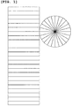
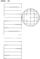
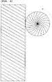
- FIGS. 1 to 3 schematically show examples of the pattern of the continuous grooves formed on the inner layer surface of the silica container according to the present invention as development views.
- a crucible which is constituted of curved surfaces and has a three-dimensional shape is just shown in a planar view, the grooves cannot be actually developed in this manner.
- a pattern in a rectangular on the left side is shown as a development view in which a pattern of grooves formed from the straight body portion to part of the curved portion is shown from a side surface, and a pattern in a circle on the right side is shown as a view in which a pattern of grooves formed from the bottom portion to part of the curved portion is shown from a top face.
- the pattern of the grooves prefferable for the pattern of the grooves to be a pattern having high symmetric properties as shown in each of FIGS. 1 to 3 .
- FIG. 1 shows an example where a radial pattern having the center of the bottom portion as its center is formed on the bottom portion and the curved portion of the silica container.
- the radial pattern (24 grooves in FIG. 1 ) having the center of the bottom portion as its center is continuous with the grooves on the straight body portion.
- FIG. 2 shows an example where a netlike pattern is formed in the bottom portion and the curved portion of the silica container.
- the respective grooves forming the netlike pattern on the bottom portion and the curved portion are continuous with grooves on the straight body portion.
- FIG. 3 shows another example where a radial pattern having the center of the bottom portion as its center is formed on the bottom portion and the curved portion of the silica container.
- the radial pattern having the center of the bottom portion as its center is continuous with grooves on the straight body portion.
- the radial pattern may not be linear as seen from the upper side of the crucible, and it may be a helix pattern.
- the pattern it is preferable for the pattern to be parallel to rotation of the crucible at the time of manufacture of the single-crystal silicon.
- the pattern shown in FIG. 3 is preferable when the crucible rotates in a counterclockwise direction (a direction of an arrow in FIG. 3 ).
- FIG. 4 shows top views each of which schematically shows a modification of the groove pattern formed in the silica container according to the present invention.
- the groove patterns shown in FIGS. 4(a), (b), and (c) are associated with the groove patterns in FIGS. 1 to 3 .
- the grooves formed on the inner layer surface of the silica container according to the present invention may be formed to reach the center of the bottom portion of the silica container as shown in FIGS. 4(a), (c), and (e) , but they may not be formed at a central part of the bottom portion of the silica container as shown in FIGS. 4(b), (d), and (f) .
- some of the plurality of continuous grooves may be formed to reach the center of the bottom portion of the silica container, and the remaining grooves may not be formed in the central part of the bottom portion of the silica container.
- the gaseous bubbles generated in the bottom portion of the silica container can be also released to the outside of the silicon melt along the continuous grooves.
- This is suitable for a container having a relatively round bottom shape.
- the grooves are not formed at the central part of the bottom portion of the silica container, since the grooves are not present immediately below the single-crystal silicon to be pulled, the gaseous bubbles are preferentially generated in or allowed to adhere to the grooves formed around the central part of the bottom portion of the groove rather than this central part, and hence an amount of the gaseous bubbles that are taken into the single-crystal silicon may be reduced in some cases.
- This is suitable for a container that has a relatively flat bottom shape.
- each continuous groove it is preferable for each continuous groove to fall within the range of 0 to 45° relative to a vertical line (that is, a perpendicular line relative to a silicon melt surface) in the straight body portion.
- a vertical line that is, a perpendicular line relative to a silicon melt surface
- FIGS. 1 and 2 shows a case where this angle (an inclined angle) is 0°.
- FIG. 3 shows a case where this angle is 30°.
- the inclined angle of each groove in the straight body portion it is preferable for the inclined angle of each groove in the straight body portion to be parallel to rotation of the crucible at the time of manufacture of the single-crystal silicon.
- the pattern in FIG. 3 is preferable when the crucible rotates in the counterclockwise direction.
- each continuous groove it is preferable to form so that it reaches a portion above a position of the silicon melt surface and more preferable to form the same so that it reaches an upper edge of the straight body portion of the silica container. If the grooves are formed to reach the upper edge of the straight body portion of the silica container, the gaseous bubbles can be assuredly released to the outside of the silicon melt irrespective of the silicon melt accommodated in the container.
- FIG. 6 shows cross-sectional shapes of each groove formed in the silica container according to the present invention.
- FIGS. 6(a) and (b) shows an example where the groove having the V-like shape or the U-like shape is formed on the surface of the inner layer 52 in the silica container.
- FIG. 6(c) shows an example where the groove having the rectangular shape is formed on the surface of the inner layer 52 of the silica container, and this shape is also referred to as a concave shape, a box shape, or an angular shape.
- the grooves having the cross-sectional shapes shown in FIG. 6 prefferably have a width of 10 to 1000 ⁇ m and a depth of 10 to 1000 ⁇ m in the cross-sectional shape. If these dimensions fall within such a range, the gaseous bubbles in the silicon melt can be more effectively released to the outside of the silicon melt. Furthermore, it is more preferable to set the width and the depth of each groove to 500 to 1000 ⁇ m and 500 to 1000 ⁇ m, respectively.
- the grooves are formed at intervals (a pitch) falling in the range of 1 to 30 mm at least in the straight body portion. It is more preferable for the intervals of the grooves to be 3 to 10 mm. Moreover, it is preferable for the intervals to be substantially equal intervals in the straight body portion.
- the single-crystal silicon pulling silica container 71 has the outer layer 51 made of the opaque silica glass containing the gaseous bubbles and the inner layer 52 made of the transparent silica glass that does not substantially contain the gaseous bubbles.
- the silica container 71 has such an outer layer 51 and an inner layer 52, soaking properties in the silica container at the time of heating can be improved.
- Bulk density of the outer layer 51 can be set to, e.g., 1.90 to 2.20 (g/cm 3 ), and bulk density of the inner layer 52 can be typically set to approximately 2.20 (g/cm 3 ), but the present invention is not restricted thereto in particular.
- OH group concentration in the outer layer 51 is preferably 10 to 300 ppm by mass, and Al concentration in the same is preferably 10 to 300 ppm by mass.
- OH group concentration in the inner layer 52 is preferably 1 to 100 ppm by mass, and Al concentration in the same is preferably 50 ppm by mass or less.
- the outer layer 51 contains 5 to 50 ppm by mass as a total value of alkali metal elements Li, Na, and K
- adsorption and fixation of the alkali metal elements can be carried out by allowing the outer layer 51 to preferably contain 10 to 300 ppm by mass or more preferably contain 20 to 50 ppm by mass of Al.
- impurity adsorption and fixation effects can be greatly improved by allowing the outer layer 51 to contain 10 to 300 ppm by mass or more preferably contain 1 to 100 ppm by mass of the OH group.
- viscosity of silica glass at a high temperature is increased, and heat deformation of the silica container at a high temperature is improved.
- An increase in the OH group concentration lowers the viscosity of the silica glass, and hence 100 ppm by mass or less is preferable.
- the Al concentration in the inner layer 52 is preferably 50 ppm by mass or less as described above.
- concentration is set in the inner layer that is in contact with the silicon melt, the single-crystal silicon can be prevented from being contaminated by the Al itself, and the effect of adsorbing and fixing the alkali metal elements by Al can be obtained.
- the OH group concentration in the inner layer 52 is preferably 1 to 100 ppm by mass as described above.
- the OH group has an effect to reduce a diffusion rate of the impurity metal elements, it also has an adverse effect to reduce etching resistance properties (insolubility with respect to the silicon melt), and hence an optimal concentration range is limited in the inner layer 52 that comes into contact with the silicon melt.
- Al and the OH group prevent movement and diffusion of the impurity metal elements in the silica glass has not yet known, it can be considered that Al adsorbs positive ions (cations) of the impurity metal elements and suppresses diffusion of them in order to keep electric charge balance of a silica glass network when Al is replaced by Si. Further, it can be considered that the OH group has an effect of adsorbing the impurity metal elements or suppressing diffusion of the impurity metal elements when hydrogen ions are replaced by metal ions.
- the inner layer 52 it is preferable for the inner layer 52 to have small content of the impurity metal elements and to have high purity.
- each of Li, Na, and K as the impurity metal elements in the inner layer 52 is set to 60 ppb by mass or less and each of Ti, V, Cr, Fe, Co, Ni, Cu, Zn, Mo, and W in the same is set to 30 ppb by mass or less or, more preferably, when each of Li, Na, and K is set to 20 ppb by mass or less and each of Ti, V, Cr, Fe, Co, Ni, Cu, Zn, Mo, and W is set to 10 ppb by mass or less, quality of the single-crystal silicon can be improved.
- the above-described silica container 71 can be manufactured as follows. A method for manufacturing a single crystal silicon pulling silica container according to the present invention will now be specifically described.
- the silica powder is melted by heat to fabricate such a silica container 71 as shown in FIG. 5 which has the outer layer 51 made of the opaque silica glass containing gaseous bubbles and the inner layer 52 made of the transparent silica glass that does not substantially contain gaseous bubbles, and which has the bottom portion, the curved portion, and the straight body portion. Then, the grooves that are continuous from at least part of the bottom portion to at least part of the straight body portion through the curved portion are formed on the surface of the inner layer 52.
- a silica powder having a particle size of 10 to 1000 ⁇ m is fabricated as a first raw material powder 11.
- this first raw material powder 11 can be fabricated by, e.g., pulverizing and sizing a block of silica as follows, the present invention is not restricted thereto.
- a block of natural silica (crystal, quartz, silica, siliceous stones, opal stones, and others which are naturally yielded) having a diameter of approximately 5 to 50 mm is heated in an air atmosphere in a temperature region of 600 to 1000°C for approximately 1 to 10 hours. Then, the block of natural silica is put into water, precipitously cooled, then taken out, and dried.
- This treatment can facilitate a subsequent treatment of pulverization and sizing using a crusher or the like, but the processing may advance to a pulverization treatment without performing this heating and precipitous cooling treatment.
- the block of natural silica is pulverized and sized with use of a crusher or the like, and its particle size is preferably adjusted to 10 to 1000 ⁇ m or more preferably 50 to 500 ⁇ m, thereby obtaining a natural silica powder.
- this natural silica powder is put into a rotary kiln constituted of a silica glass tube having an inclined angle, a hydrogen chloride (HCl) or chlorine (Cl 2 ) gas containing atmosphere is provided in the kiln, and a purification treatment is carried out by performing heating at 700 to 1100°C for approximately 1 to 100 hours.
- the processing may advance to a subsequent treatment without performing this purification treatment.
- the first raw material powder 11 obtained after the above-described process is crystalline silica
- amorphous silica glass scraps may be used as the first raw material powder 11 depending on a user application of the silicon container.
- a particle size of the first raw material powder 11 is preferably set to 10 to 1000 ⁇ m and more preferably set to 50 to 500 ⁇ m.
- Silica purity of the first raw material powder 11 is preferably set to 99.99% by mass or more, or it is more preferably set to 99.999% by mass or more. Furthermore, according to the method for manufacturing a silica container of the present invention, even if the silica purity of the first raw material powder 11 is as relatively low as less than 99.999% by mass, the silica container to be manufactured can sufficiently prevent impurity contamination with respect to accommodated matters. Therefore, the silica container can be manufactured at lower cost than those in conventional examples.
- the first raw material powder 11 may contain Al preferably in the range of 10 to 300 ppm by mass.
- Al can be obtained by using a water or alcohol solution of, e.g., a nitrate, an acetate, a carbonate, a chloride, or the like, putting and immersing the silica powder in such a solution, and then performing drying.
- FIG. 9 is a cross-sectional view showing an outline of the mold used for temporarily molding the first raw material powder 11.
- a mold 101 used in the present invention is constituted of a member of graphite or the like and has rotational symmetry.
- pressure-reducing holes 103 may be distributed and formed in an inner wall 102 of the mold 101.
- the pressure-reducing holes 103 are continuous with a pressure-reducing path 104.
- a pressure-reducing path 105 also runs through a rotary shaft 106 configured to rotate the mold 101, and vacuum drawing can be carried out from this path.
- the first raw material powder 11 is introduced to the inner wall 102 of this mold 101, and the first raw material powder 11 is temporarily molded into a predetermined shape associated with the inner wall 102 of the mold 101, thus obtaining a temporary compact 41 (see
- the first raw material powder 11 is gradually put to the inner wall 102 of the mold 101 while rotating the mold 101, and it is molded into a container shape by utilizing centrifugal force. Further, a tabular inner mold (not shown) is brought into contact with the rotating powder body from the inner side, whereby a thickness of the temporary compact 41 may be adjusted to a predetermined amount.
- a method for supplying this first raw material 11 to the mold 101 is not restricted in particular, for example, a hopper including an agitating screw and a measuring feeder may be used. In this case, the first raw material 11 that has filled the hopper is agitated by using the agitating screw, and it is supplied while adjusting a supply mount by using the agitating screw and the measuring feeder.
- the temporary compact 41 is heated and molten by the discharge heating melting method so that at least an outer portion of the temporary compact 41 is turned to an outer layer 51 made of opaque silica glass and an inner portion of the same is turned to an inner layer 52 made of transparent silica glass.
- an outer peripheral portion of the temporary compact 41 can be formed into a sintered body, and an inner portion of the temporary compact is formed into a molten glass body, thus fabricating the silica container 71.
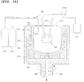
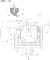
- An apparatus configured to fabricate the silica container 71 comprises the rotatable mold 101 having the rotational symmetry, a rotary motor (not shown), carbon electrodes 212 that can function as a heat source of discharge heating melting (which is also referred to as arc melting or arc discharge melting), electric wires 212a, a high-voltage power supply unit 211, a lid 213, and others. Further, it also comprises constituent members configured to check an atmospheric gas supplied from the inner side of the temporary compact, e.g., a hydrogen gas supply cylinder 411, an inert gas supply cylinder 412, a mixed gas supply tube 420, and others.
- this apparatus can be continuously used in case of further forming a layer made of transparent silica glass on a surface portion of the inner layer as will be described later.
- the hydrogen gas is supplied from the hydrogen gas supply cylinder 411, the inert gas (e.g., nitrogen (N 2 ), argon (Ar), or helium (He)) is supplied from the inert gas supply cylinder 412, these gases are mixed, and a mixture is supplied from the inner side of the temporary compact 41 through the mixed gas supply tube 420.
- the inert gas e.g., nitrogen (N 2 ), argon (Ar), or helium (He)
- N 2 nitrogen
- Ar argon
- He helium
- the mold 101 having the temporary compact 41 therein is rotated at a fixed rate, a degassing vacuum pump (not shown) is activated, depressurization is carried out from the outer side of the temporary compact 41 via the pressure-reducing holes 103 and the pressure-reducing paths 104 and 105, and application of a voltage between the carbon electrodes 212 is started.
- a melting temperature region (which is assumed to be approximately 1800 to 2000°C) of the silica powder is formed in the inner surface portion of the temporary compact 41, and melting starts from the outermost layer portion.
- a depressurization degree of vacuum drawing effected by the degassing vacuum pump increases (a pressure is precipitously lowered), and a change into a molten silica glass layer advances from the inner side toward the outer side while releasing a dissolved gas contained in the first raw material powder 11.
- the inner layer 52 constituted of the transparent silica glass layer is provided, and approximately remaining half of the same on the outer side is turned to the outer layer 51 made of the opaque silica glass. It is preferable to set the depressurization degree to 10 4 Pa or less and more preferable to set the same to 10 3 Pa or less.
- discharge heating can be carried out at a normal temperature without performing depressurization
- the outer portion of the temporary compact 41 can be made of the opaque silica glass
- the inner portion of the same can be made of the transparent silica glass.
- grooves can be formed in the silica container 71 formed by the above-described process, a layer made of the transparent silica glass can be further formed on the surface portion of the inner layer 52 of the silica layer 71 so as to increase a thickness of the inner layer before forming the grooves. This method will now be described with reference to FIG. 8 .
- the process from the beginning to formation of the silica container 71 is performed (see FIGS. 8(1) to (3 )).
- a silica powder 12 having a particle size of 10 to 1000 ⁇ m and higher purity that the first raw material powder 11 is fabricated.
- a method for fabricating the second raw material powder may be the same as that of the first raw material powder except raising the purity.
- a material of the second raw material powder 12 it is possible to use a natural quartz powder, a natural crystal powder, a synthetic cristobalite powder, or a synthetic silica glass powder subjected to a purification treatment.
- a crystalline silica powder is preferable for the purpose of reducing an amount of gaseous bubbles in the inner layer, or a synthetic powder is preferable for the purpose of providing the inner layer made of high-purity transparent silica glass. It is preferable to set a particle size of the second raw material powder 12 to 100 to 500 ⁇ m.
- the second raw material powder 12 it is preferable to contain 99.9999% by mass or more of a silica component (SiO 2 ), 60 ppb by mass or less, which is more desirably 20 ppb by mass or less, of each of alkali metal elements Li, Na, and K, or 30 ppb by mass or less, which is more desirably 10 ppb by mass or less, of each of Ti, V, Cr, Fe, Co, Ni, Cu, Zn, Mo, and W.
- SiO 2 silica component
- a layer made of the transparent silica glass is formed by using the second raw material powder 12 on the surface portion of the inner layer 52 of the silica container 71 at least after the discharge heating melting process (after (3) of FIG. 8 ) and before formation of the grooves ((5) of FIG. 8 ), thereby increasing the thickness of the inner layer.
- This process is effected by spreading the second raw material powder 12 from the upper side of the silica container 71 and performing heating and melting based on the discharge heating melting method.
- a basic forming method of this process is conforming to, e.g., contents disclosed in Patent Literature 6 and Patent Literature 7.
- the hydrogen gas supply cylinder 411, the inert gas supply cylinder 412, the mixed gas supply tube 420, and others may be provided.
- the mold 101 is set to a predetermined rotational speed, a high voltage is gradually applied from the high-voltage power supply unit 211 and, at the same time, the second raw material powder 12 is gradually spread from the upper side of the silica container 71 by using the raw material hopper 303.
- a melting temperature region (which is considered to be approximately 1800 to 2000°C) of the silica powder is formed in the silica container 71, and hence the spread second raw material powder 12 adheres to the inner surface of the silica container 71 as molten particles of silica.
- the carbon electrodes 212, a raw material powder input opening, and the lid 213 disposed at an upper opening portion of the silica container 71 are mechanisms whose positions can be changed with respect to the silica container 71 to some extent, and changing these positions enables increasing the thickness of the inner layer 52 which is uniform on the entire inner surface of the silica container 71. It is to be noted that a portion of the inner layer 52 thickened with use of the second raw material powder 12 is represented as an inner layer (an additional layer) 52' in FIG. 13 .
- grooves are formed on the inner layer 52 of the silica container 71 ( FIG. 7(4), FIG. 8(5) ).
- a grinder having a diamond grinding plate which rotates at a high speed incorporated therein can be used.
- the diamond grinding plate (a wheel) a metal bonded grinding plate having a diamond fixed by an alloy can be used at low cost, but a resin bonded grinding plate fixed by using a resin or vitrified bonded grinding plate fixed by multicomponent-based glass can be used in order to avoid machining contamination on the inner surface of the container.
- a laser beam machine having a carbon dioxide (CO 2 ) laser or the like incorporated therein can be used. Since laser machining is a contactless machining method, it can avoid machining contamination on the inner surface of the silica container.
- the single-crystal silicon pulling silica container 71 according to the present invention can be obtained.
- a single-crystal silicon pulling silica container was manufactured based on the processes (1) to (4) shown in FIG. 7 .
- a natural quartz powder that has silica (SiO 2 ) purity of 99.999% by mass or more and a particle size of 100 to 300 ⁇ m and that was doped with 50 ppm by mass of Al was prepared as the first raw material powder 11.
- a dried mixed gas containing 97% by volume of N 2 and 3% by volume of H 2 was used as an atmospheric gas at the time of melting a temporary compact.
- Continuous grooves each having a V-like shape were formed in such a netlike pattern as shown in FIG. 2 and FIG. 4(c) on a surface of an inner layer of the silica container.
- a groove width was 700 ⁇ m
- a groove depth was 600 ⁇ m
- an angle relative to a vertical line of each groove in a straight body portion was 0°
- each groove interval was 20 mm in the straight body portion.
- Other conditions are written in Table 1.
- a silica container was manufactured like Example 1, and V-shaped grooves were formed on a surface of an inner layer of the silica container as shown in FIG. 1 except a bottom portion where the grooves were formed in such a radial pattern as shown in FIG. 4(b) .
- a groove width was 700 ⁇ m
- a groove depth was 600 ⁇ m
- an angle relative to a vertical line of each groove in a straight body portion was 0°
- each groove interval was 15 mm in the straight body portion.
- a single-crystal silicon pulling silica container was manufactured based on the processes (1) to (5) shown in FIG. 8 .
- a natural quartz powder that has silica purity of 99.999% by mass or more and a particle size of 100 to 300 ⁇ m and that was doped with 60 ppm by mass of Al was used as the first raw material powder.
- a high-purity synthetic cristobalite powder having silica purity of 99.9999% by mass or more and a particle size of 100 to 300 ⁇ m was used.
- As an atmospheric gas at the time of melting a dried mixed gas containing 90% by volume of He and 10% by volume of H 2 was used.
- U-shaped grooves were formed in such a radial (a radial vortex shape) pattern as shown in FIG. 3 and FIG. 4(e) on a surface of an inner layer of the silica container.
- a groove width was 700 ⁇ m
- a groove depth was 500 ⁇ m
- an angle relative to a vertical line of each groove in a straight body portion was 30°
- each groove interval was 10 mm in the straight body portion.
- Other conditions are written in Table 2.
- a first raw material powder doped with Al and a high-purity second raw material powder which are the same as those in Example 3 were used. Moreover, an atmospheric gas at the time of melting was also the same as that in Example 3.
- U-shaped grooves were formed on an inner surface portion of the silica container as shown in FIG. 3 except a bottom portion where the grooves were formed in such a radial (a radial vortex shape) pattern as shown in FIG. 4(f) .
- a groove width was 700 ⁇ m
- a groove depth was 500 ⁇ m
- an angle relative to a vertical line of each groove in a straight body portion was 30°
- each groove interval was 15 mm in the straight body portion.
- a natural quartz powder having silica purity of 99.999% by mass or more and a particle size of 100 to 300 ⁇ m was used as a first raw material powder.
- a temporary compact was molten based on the reduced-pressure arc discharge melting method. No groove was formed on an inner surface portion of the silica container.
- a first raw material powder was the same as that in Comparative Example 2, and a second raw material powder is the same as those in Examples 3 and 4.
- a temporary compact was molten by a normal-pressure arc melting method in air, and a technique for increasing a thickness of the inner layer was carried out by the normal-pressure arc melting method in air based on spreading of the second raw material powder. No groove was formed on an inner surface portion of the silica container.
- a thickness of each layer was determined by measuring a container cross section at a central (1/2) portion of an entire height of a sidewall of the silicon container with use of a scale.
- ICP-AES plasma atomic emission spectrometry
- ICP-MS plasma mass spectrometry
- AS atomic absorption spectrophotometry
- Metal polysilicon having purity of 99.99999% by mass was put into each manufactured silica container, a temperature was increased to provide a silicon melt, then pulling single-crystal silicon was repeated for three times (multi-pulling), and a success rate of single-crystal growth was evaluated.
- pulling conditions an argon (Ar) gas 100% atmosphere was provided in the pulling apparatus, a pulling rate was 0.5 mm/minute, the number of revolutions was 10 rpm, a single-crystal silicon dimension was set to a diameter of 300 mm and a length of 600 mm, and an operating time of one batch was set to approximately 100 hours. Success ratios of repetition of the single-crystal growth for three times were classified as follows. Succeeded three times good Succeeded twice slightly poor Once or less poor
- the number of defect-free silicon wafers 200 good
- the number of defect-free silicon wafers 199 to 198 slightly poor
- the number of defect-free silicon wafers 197 or less poor
- Example number Example 1
- Example 2 First raw material powder Natural quartz powder with particle size of 100 to 300 ⁇ m Natural quartz powder with particle size of 100 to 300 ⁇ m Second raw material power None None Temporary compact molding method Rotational molding method in graphite mold Rotational molding method in graphite mold Temporary compact melting method Reduced-pressure arc discharge melting method Reduced-pressure arc discharge melting method Temporary compact melting atmospheric gas N 2 97% by volume, H 2 3% by volume N 2 97% by volume, H 2 3% by volume Additional layer melting atmospheric gas - - Atmospheric gas in cooling N 2 80% by volume, O 2 20% by volume N 2 80% by volume, O 2 20% by volume Physical properties of outer layer Color tone White opaque White opaque Outer diameter, Height, Thickness (mm) Outer diameter 800 ⁇ Height 360 ⁇ Thickness 13 Outer diameter 800 ⁇ Height 360 ⁇ Thickness 13 OH group (ppm by mass) 50 50 Al (ppm by mass) 50 50 Physical properties of inner layer Color tone Colorless and transparent Colorless and
- Example 4 (netlike) V-shaped grooves
- FIG. 4(b) (radial excluding central part) V-shaped grooves Evaluations Single-crystal pulling Slightly poor Slightly poor Voids and pinholes Slightly poor Good Impurity level of inner layer Slightly poor Slightly poor [Table 2]
- Example number Example 3
- Example 4 First raw material powder Natural quartz powder with particle size of 100 to 300 ⁇ m Natural quartz powder with particle size of 100 to 300 ⁇ m Second raw material powder Synthetic cristobalite powder with particle size of 100 to 300 ⁇ m Synthetic cristobalite powder with particle size of 100 to 300 ⁇ m
- Temporary compact molding method Rotational molding method in graphite mold Rotational molding method in graphite mold
- Temporary compact melting method Reduced-pressure arc discharge melting method
- Reduced-pressure arc discharge melting method Temporary compact melting atmospheric gas He 90% by volume, H 2 10% by volume He 90% by volume, H 2 10% by volume Additional layer melting atmospheric gas He 90% by volume, H
Landscapes
- Chemical & Material Sciences (AREA)
- Engineering & Computer Science (AREA)
- Organic Chemistry (AREA)
- Materials Engineering (AREA)
- Chemical Kinetics & Catalysis (AREA)
- Life Sciences & Earth Sciences (AREA)
- General Chemical & Material Sciences (AREA)
- Geochemistry & Mineralogy (AREA)
- Crystallography & Structural Chemistry (AREA)
- Metallurgy (AREA)
- Manufacturing & Machinery (AREA)
- Crystals, And After-Treatments Of Crystals (AREA)
- Glass Melting And Manufacturing (AREA)
- Glass Compositions (AREA)
Claims (15)
- Siliziumbehälter zur Züchtung eines Silizium-Einkristalls, umfassend eine aus opakem Quarzglas, welches gasförmige Blasen enthält, hergestellte äußere Schicht, und eine aus transparentem Quarzglas, welches im Wesentlichen keine gasförmigen Blasen enthält, hergestellte innere Schicht, wobei der Behälter auch einen Bodenabschnitt, einen gebogenen Abschnitt, und einen geraden Körperabschnitt umfasst,
wobei kontinuierliche Aussparungen auf einer Oberfläche der inneren Schicht von mindestens einem Teil des Bodenabschnitts zu mindestens einem Teil des geraden Körperabschnitts durch den gebogenen Abschnitt gebildet sind. - Siliziumbehälter zur Züchtung eines Silizium-Einkristalls nach Anspruch 1,
wobei die Aussparungen gebildet sind, um ein Zentrum des Bodenabschnitts zu erreichen. - Siliziumbehälter zur Züchtung eines Silizium-Einkristalls nach Anspruch 1,
wobei die Aussparungen nicht in einem zentralen Teil des Bodenabschnitts gebildet sind. - Siliziumbehälter zur Züchtung eines Silizium-Einkristalls nach einem beliebigen der Ansprüche 1 bis 3,
wobei die Aussparungen in einem netzartigen Muster oder einem radialen Muster auf dem Bodenabschnitt und dem gebogenen Abschnitt gebildet sind, wobei das radiale Muster auf ein Zentrum des Bodenabschnitts hin zentriert ist. - Siliziumbehälter zur Züchtung eines Silizium-Einkristalls nach einem beliebigen der Ansprüche 1 bis 4,
wobei die Aussparungen gebildet sind, um einen oberen Rand des geraden Körperabschnitts zu erreichen. - Siliziumbehälter zur Züchtung eines Silizium-Einkristalls nach einem beliebigen der Ansprüche 1 bis 5,
wobei eine Querschnittsform jeder der Aussparungen eine beliebige einer V-artigen Form, eine U-artigen Form und einer rechtwinkligen Form ist. - Siliziumbehälter zur Züchtung eines Silizium-Einkristalls nach einem beliebigen der Ansprüche 1 bis 6,
wobei die Aussparungen in Intervallen gebildet sind, die in den Bereich von 1 bis 30 mm in mindestens dem geraden Körperabschnitt fallen. - Siliziumbehälter zur Züchtung eines Silizium-Einkristalls nach einem beliebigen der Ansprüche 1 bis 7,
wobei die äußere Schicht eine OH Gruppen-Konzentration von 10 bis 300 ppm, bezogen auf die Masse und eine Al Konzentration von 10 bis 300 ppm, bezogen auf die Masse aufweist. - Siliziumbehälter zur Züchtung eines Silizium-Einkristalls nach einem beliebigen der Ansprüche 1 bis 8,
wobei die innere Schicht eine OH Gruppen-Konzentration von 1 bis 100 ppm, bezogen auf die Masse und eine Al Konzentration von 50 ppm oder weniger, bezogen auf die Masse aufweist. - Verfahren zum Herstellen eines Siliziumbehälters zur Züchtung eines Silizium-Einkristalls, umfassend: Durchführen von Erhitzen und Schmelzen eines Siliziumpulvers, um einen Siliziumbehälter herzustellen, der eine aus einem opakem Quarzglas hergestellte, gasförmige Blasen enthaltende äußere Schicht und eine aus transparentem Quarzglas hergestellte, im Wesentlichen keine gasförmige Blasen enthaltende innere Schicht umfasst, wobei der Siliziumbehälter auch einen Bodenabschnitt, einen gebogenen Abschnitt und einen geraden Körperabschnitt umfasst; und dann Bilden kontinuierlicher Aussparungen auf einer Oberfläche der inneren Schicht von mindesten einem Teil des Bodenabschnitts bis zu mindestens einem Teil des geraden Körperabschnitts über den gebogenen Abschnitt.
- Verfahren zum Herstellen eines Siliziumbehälters zur Züchtung eines Silizium-Einkristalls nach Anspruch 10,
wobei die Herstellung des Siliziumbehälters, die durch Erhitzen und Schmelzen des Siliziumpulvers bewirkt wird, durchgeführt wird basierend auf:einem Schritt des Herstellens eines Siliziumpulvers mit einer Partikelgröße von 10 bis 1000 µm als einem ersten Rohmaterialpulver;einem Schritt des Einsetzens des ersten Rohmaterialpulvers in eine Form mit rotationaler Symmetrie, und temporäre Formung davon in eine vorgegebene Form, die mit einer inneren Wand der Form während Rotation der Form assoziiert ist, dadurch Erhalten eines temporären Presskörpers; undeinen Entladungs-Heizschmelzschritt des Platzierens von Kohlenstoffelektroden in den temporären Presskörper, und Erhitzen und Schmelzen des temporären Presskörpers durch das Entladungs-Heizschmelzverfahren, so dass mindestens ein äußerer Seitenabschnitt des temporären Presskörpers aus dem opakem Quarzglas hergestellt ist und ein innerer Seitenabschnitt des Gleichen aus dem transparenten Quarzglas hergestellt ist. - Verfahren zum Herstellen eines Siliziumbehälters zur Züchtung eines Silizium-Einkristalls nach Anspruch 11, umfassend:einen Schritt des Herstellens eines Siliziumpulvers mit einer Partikelgröße von 10 bis 1000 µm und einer höheren Reinheit als dem ersten Rohmaterialpulver als ein zweites Rohmaterialpulver; undeinen Schritt des Erhitzens und Schmelzens des zweiten Rohmaterialpulvers durch ein Entladungs-Heizschmelzverfahren, während Auftragen davon von einer oberen Seite des Siliziumbehälters und des Weiteren Bilden einer aus transparentem Siliziumglas hergestellten Schicht auf einem Oberflächenabschnitt einer inneren Schicht des Siliziumbehälters, mindestens nach dem Entladungs-Heizschmelzschrift und vor der Bildung der Aussparungen.
- Verfahren zum Herstellen eines Siliziumbehälters zur Züchtung eines Silizium-Einkristalls nach Anspruch 11 oder Anspruch 12,
wobei, während dem Entladungs-Heizschmelzschritt, der Druck auf dem temporären Presskörper von einer äußeren Seite der Form herabgesetzt wird, um den temporären Presskörper zu entgasen. - Verfahren zum Herstellen eines Siliziumbehälters zur Züchtung eines Silizium-Einkristalls nach einem beliebigen der Ansprüche 11 bis 13,
wobei, während dem Entladungs-Heizschmelzschritt, ein 1 bis 10 Vol.% eines Wasserstoffgases enthaltendes inertes gemischtes Gas von einer inneren Seite des temporären Presskörpers zugeführt wird. - Verfahren zum Herstellen eines Siliziumbehälters zur Züchtung eines Silizium-Einkristalls nach einem beliebigen der Ansprüche 10 bis 14,
wobei eine Querschnittsform eines distalen Endes einer Drehschleifenplatte einer Schleifvorrichtung für die Bildung von Aussparungen, die in der Bildung der Aussparungen verwendet wird, eine beliebige von einer V-artigen Form, einer U-artigen Form, und einer rechtwinkligen Form aufweist.
Applications Claiming Priority (2)
| Application Number | Priority Date | Filing Date | Title |
|---|---|---|---|
| JP2011271565A JP5250097B2 (ja) | 2011-12-12 | 2011-12-12 | 単結晶シリコン引き上げ用シリカ容器及びその製造方法 |
| PCT/JP2012/006291 WO2013088617A1 (ja) | 2011-12-12 | 2012-10-02 | 単結晶シリコン引き上げ用シリカ容器及びその製造方法 |
Publications (3)
| Publication Number | Publication Date |
|---|---|
| EP2687623A1 EP2687623A1 (de) | 2014-01-22 |
| EP2687623A4 EP2687623A4 (de) | 2015-01-07 |
| EP2687623B1 true EP2687623B1 (de) | 2016-04-06 |
Family
ID=48612100
Family Applications (1)
| Application Number | Title | Priority Date | Filing Date |
|---|---|---|---|
| EP12857311.0A Active EP2687623B1 (de) | 2011-12-12 | 2012-10-02 | Siliciumbehälter zur züchtung eines siliciumeinkristalls und herstellungsverfahren dafür |
Country Status (7)
| Country | Link |
|---|---|
| US (1) | US9382640B2 (de) |
| EP (1) | EP2687623B1 (de) |
| JP (1) | JP5250097B2 (de) |
| KR (1) | KR101504953B1 (de) |
| CN (1) | CN103476974B (de) |
| TW (1) | TWI509117B (de) |
| WO (1) | WO2013088617A1 (de) |
Families Citing this family (14)
| Publication number | Priority date | Publication date | Assignee | Title |
|---|---|---|---|---|
| US10253195B2 (en) | 2014-11-24 | 2019-04-09 | Ppg Industries Ohio, Inc. | Coreactive materials and methods for three-dimensional printing |
| CN107735371B (zh) * | 2015-07-15 | 2021-03-02 | 贺利氏石英美国有限责任公司 | 用于将不透明的熔凝石英与透明的熔凝石英连接的工艺 |
| AT16098U1 (de) * | 2017-05-03 | 2019-01-15 | Plansee Se | Glasschmelzkomponente |
| US12384097B2 (en) | 2017-08-18 | 2025-08-12 | Ppg Industries Ohio, Inc. | Additive manufacturing using reactive compositions |
| US10434704B2 (en) | 2017-08-18 | 2019-10-08 | Ppg Industries Ohio, Inc. | Additive manufacturing using polyurea materials |
| JP6941042B2 (ja) * | 2017-12-12 | 2021-09-29 | 信越石英株式会社 | モールド及び石英ガラスるつぼの製造方法 |
| KR20210124439A (ko) | 2019-02-11 | 2021-10-14 | 피피지 인더스트리즈 오하이오 인코포레이티드 | 밀봉 캡의 3차원 인쇄 |
| CN113710481A (zh) | 2019-02-11 | 2021-11-26 | Ppg工业俄亥俄公司 | 多层系统和制造多层系统的方法 |
| EP3924187A1 (de) | 2019-02-11 | 2021-12-22 | PPG Industries Ohio, Inc. | Elastomere zusammensetzungen und verfahren zur verwendung |
| MX2021009606A (es) | 2019-02-11 | 2021-11-12 | Ppg Ind Ohio Inc | Métodos para fabricar componentes de sellado químicamente resistentes. |
| JP7761376B2 (ja) | 2020-07-30 | 2025-10-28 | 信越石英株式会社 | 石英ガラスるつぼ |
| CN113201789B (zh) * | 2021-03-24 | 2022-11-04 | 新沂市中鑫光电科技有限公司 | 一种能够快速导热的高强度电弧石英坩埚 |
| JP2023173983A (ja) * | 2022-05-27 | 2023-12-07 | モメンティブ・テクノロジーズ・山形株式会社 | 石英ガラスルツボ及びその製造方法 |
| CN121520843B (zh) * | 2026-01-19 | 2026-03-31 | 福建省三明市盛达化工有限公司 | 一种高纯二氧化硅高温相变炉 |
Family Cites Families (26)
| Publication number | Priority date | Publication date | Assignee | Title |
|---|---|---|---|---|
| JPS584718A (ja) | 1981-06-30 | 1983-01-11 | Nippon Chibagaigii Kk | 新規適応症に用うる医薬製剤 |
| JPS6476993A (en) * | 1982-04-28 | 1989-03-23 | Nippon Carbon Co Ltd | Graphite crucible for pulling up silicon single crystal |
| JPH01148718A (ja) | 1987-12-03 | 1989-06-12 | Shin Etsu Handotai Co Ltd | 石英るつぼの製造方法 |
| US4935046A (en) | 1987-12-03 | 1990-06-19 | Shin-Etsu Handotai Company, Limited | Manufacture of a quartz glass vessel for the growth of single crystal semiconductor |
| JPH0729871B2 (ja) * | 1987-12-03 | 1995-04-05 | 信越半導体 株式会社 | 単結晶引き上げ用石英るつぼ |
| JP2630649B2 (ja) * | 1989-07-05 | 1997-07-16 | 東芝セラミックス株式会社 | 単結晶引上げ用石英ガラスルツボ |
| JP2973057B2 (ja) * | 1992-06-23 | 1999-11-08 | 三菱マテリアルクォーツ株式会社 | シリコン単結晶引上げ用石英ルツボとその製造方法 |
| JPH07206451A (ja) | 1993-12-29 | 1995-08-08 | Nippon Steel Corp | 合成石英ガラスの製造方法 |
| JP3702904B2 (ja) | 1994-04-04 | 2005-10-05 | セイコーエプソン株式会社 | 合成石英ガラスの製造方法 |
| JPH07277743A (ja) | 1994-04-04 | 1995-10-24 | Nippon Steel Corp | 合成石英ガラスの製造方法 |
| JPH0840796A (ja) * | 1994-08-03 | 1996-02-13 | Hitachi Ltd | 単結晶シリコン製造装置 |
| JP3764776B2 (ja) | 1996-03-18 | 2006-04-12 | 信越石英株式会社 | 単結晶引き上げ用石英ガラスるつぼ及びその製造方法 |
| JP3798849B2 (ja) | 1996-07-09 | 2006-07-19 | 信越石英株式会社 | 石英ルツボの製造装置及び方法 |
| JPH10297992A (ja) * | 1997-04-25 | 1998-11-10 | Sumitomo Metal Ind Ltd | 結晶引上げ用るつぼおよび結晶引上げ用部品 |
| DE10114484C2 (de) | 2001-03-24 | 2003-10-16 | Heraeus Quarzglas | Verfahren für die Herstellung eines Komposit-Werkstoffs mit einem SiO¶2¶-Gehalt von mindestens 99 Gew.-%, und Verwendung des nach dem Verfahren erhaltenen Komposit-Werkstoffs |
| DE10262015B3 (de) | 2002-09-20 | 2004-07-15 | Heraeus Quarzglas Gmbh & Co. Kg | Verfahren für die Herstellung eines opaken Quarzglas-Kompositwerkstoffs |
| JP4994576B2 (ja) * | 2004-03-23 | 2012-08-08 | コバレントマテリアル株式会社 | シリカガラスルツボ |
| JP4466175B2 (ja) * | 2004-04-14 | 2010-05-26 | 株式会社Sumco | 石英ルツボ |
| JP4848974B2 (ja) * | 2007-02-20 | 2011-12-28 | 信越半導体株式会社 | 黒鉛ルツボおよびこれを備えたシリコン単結晶製造装置 |
| JP4799536B2 (ja) * | 2007-12-14 | 2011-10-26 | ジャパンスーパークォーツ株式会社 | 大径のシリコン単結晶インゴット中のピンホール欠陥の低減を可能とする大径シリコン単結晶インゴット引上げ用高純度石英ガラスルツボ |
| CN101965418B (zh) * | 2008-02-29 | 2012-12-05 | 日本超精石英株式会社 | 单晶硅拉晶用石英坩埚及其制造方法 |
| JP5042971B2 (ja) | 2008-11-28 | 2012-10-03 | 株式会社Sumco | シリコン単結晶引き上げ用石英ガラスルツボ及びその製造方法 |
| JP5043048B2 (ja) * | 2009-01-21 | 2012-10-10 | 株式会社Sumco | シリコン単結晶引き上げ用石英ガラスルツボ及びその製造方法 |
| JP4951040B2 (ja) | 2009-08-05 | 2012-06-13 | 信越石英株式会社 | シリカ容器及びその製造方法 |
| US8496752B2 (en) * | 2009-09-02 | 2013-07-30 | Heraeus Shin-Etsu America, Inc. | Method and apparatus for venting gas between a crucible and a susceptor |
| JP2012017239A (ja) * | 2010-12-22 | 2012-01-26 | Covalent Materials Corp | ルツボ構造 |
-
2011
- 2011-12-12 JP JP2011271565A patent/JP5250097B2/ja active Active
-
2012
- 2012-10-02 CN CN201280018220.6A patent/CN103476974B/zh active Active
- 2012-10-02 KR KR1020137023915A patent/KR101504953B1/ko active Active
- 2012-10-02 EP EP12857311.0A patent/EP2687623B1/de active Active
- 2012-10-02 WO PCT/JP2012/006291 patent/WO2013088617A1/ja not_active Ceased
- 2012-10-02 US US14/004,085 patent/US9382640B2/en active Active
- 2012-10-30 TW TW101140103A patent/TWI509117B/zh active
Also Published As
| Publication number | Publication date |
|---|---|
| KR101504953B1 (ko) | 2015-03-23 |
| TW201337049A (zh) | 2013-09-16 |
| EP2687623A1 (de) | 2014-01-22 |
| JP5250097B2 (ja) | 2013-07-31 |
| KR20130122682A (ko) | 2013-11-07 |
| TWI509117B (zh) | 2015-11-21 |
| JP2013121902A (ja) | 2013-06-20 |
| CN103476974A (zh) | 2013-12-25 |
| US9382640B2 (en) | 2016-07-05 |
| EP2687623A4 (de) | 2015-01-07 |
| WO2013088617A1 (ja) | 2013-06-20 |
| US20140053772A1 (en) | 2014-02-27 |
| CN103476974B (zh) | 2016-02-10 |
Similar Documents
| Publication | Publication Date | Title |
|---|---|---|
| EP2687623B1 (de) | Siliciumbehälter zur züchtung eines siliciumeinkristalls und herstellungsverfahren dafür | |
| KR101333190B1 (ko) | 실리카 용기 및 그 제조 방법 | |
| KR101313647B1 (ko) | 실리카 용기 및 그 제조방법 | |
| JP5462423B1 (ja) | 単結晶シリコン引き上げ用シリカ容器及びその製造方法 | |
| JP4969632B2 (ja) | シリカ粉及びシリカ容器並びにそれらの製造方法 | |
| KR101268483B1 (ko) | 실리카 용기 및 그 제조방법 | |
| JP5608257B1 (ja) | 単結晶シリコン引き上げ用シリカ容器及びその製造方法 | |
| US9376761B2 (en) | Single-crystal silicon pulling silica container and method for producing the same | |
| JP5608258B1 (ja) | 単結晶シリコン引き上げ用シリカ容器及びその製造方法 |
Legal Events
| Date | Code | Title | Description |
|---|---|---|---|
| PUAI | Public reference made under article 153(3) epc to a published international application that has entered the european phase |
Free format text: ORIGINAL CODE: 0009012 |
|
| 17P | Request for examination filed |
Effective date: 20130926 |
|
| AK | Designated contracting states |
Kind code of ref document: A1 Designated state(s): AL AT BE BG CH CY CZ DE DK EE ES FI FR GB GR HR HU IE IS IT LI LT LU LV MC MK MT NL NO PL PT RO RS SE SI SK SM TR |
|
| A4 | Supplementary search report drawn up and despatched |
Effective date: 20141205 |
|
| RIC1 | Information provided on ipc code assigned before grant |
Ipc: C30B 29/06 20060101AFI20141201BHEP Ipc: C03B 20/00 20060101ALI20141201BHEP Ipc: C03C 3/06 20060101ALI20141201BHEP Ipc: C30B 15/10 20060101ALI20141201BHEP |
|
| DAX | Request for extension of the european patent (deleted) | ||
| REG | Reference to a national code |
Ref country code: DE Ref legal event code: R079 Ref document number: 602012016917 Country of ref document: DE Free format text: PREVIOUS MAIN CLASS: C30B0029060000 Ipc: C03B0019090000 |
|
| RIC1 | Information provided on ipc code assigned before grant |
Ipc: C30B 29/06 20060101ALI20150731BHEP Ipc: C30B 15/10 20060101ALI20150731BHEP Ipc: C03B 20/00 20060101ALI20150731BHEP Ipc: C03C 3/06 20060101ALI20150731BHEP Ipc: C03B 19/09 20060101AFI20150731BHEP |
|
| GRAP | Despatch of communication of intention to grant a patent |
Free format text: ORIGINAL CODE: EPIDOSNIGR1 |
|
| INTG | Intention to grant announced |
Effective date: 20151002 |
|
| GRAS | Grant fee paid |
Free format text: ORIGINAL CODE: EPIDOSNIGR3 |
|
| GRAA | (expected) grant |
Free format text: ORIGINAL CODE: 0009210 |
|
| AK | Designated contracting states |
Kind code of ref document: B1 Designated state(s): AL AT BE BG CH CY CZ DE DK EE ES FI FR GB GR HR HU IE IS IT LI LT LU LV MC MK MT NL NO PL PT RO RS SE SI SK SM TR |
|
| REG | Reference to a national code |
Ref country code: GB Ref legal event code: FG4D |
|
| REG | Reference to a national code |
Ref country code: AT Ref legal event code: REF Ref document number: 787619 Country of ref document: AT Kind code of ref document: T Effective date: 20160415 Ref country code: CH Ref legal event code: EP |
|
| REG | Reference to a national code |
Ref country code: IE Ref legal event code: FG4D |
|
| REG | Reference to a national code |
Ref country code: DE Ref legal event code: R096 Ref document number: 602012016917 Country of ref document: DE |
|
| REG | Reference to a national code |
Ref country code: LT Ref legal event code: MG4D Ref country code: NL Ref legal event code: MP Effective date: 20160406 |
|
| REG | Reference to a national code |
Ref country code: AT Ref legal event code: MK05 Ref document number: 787619 Country of ref document: AT Kind code of ref document: T Effective date: 20160406 |
|
| PG25 | Lapsed in a contracting state [announced via postgrant information from national office to epo] |
Ref country code: NL Free format text: LAPSE BECAUSE OF FAILURE TO SUBMIT A TRANSLATION OF THE DESCRIPTION OR TO PAY THE FEE WITHIN THE PRESCRIBED TIME-LIMIT Effective date: 20160406 |
|
| PG25 | Lapsed in a contracting state [announced via postgrant information from national office to epo] |
Ref country code: PL Free format text: LAPSE BECAUSE OF FAILURE TO SUBMIT A TRANSLATION OF THE DESCRIPTION OR TO PAY THE FEE WITHIN THE PRESCRIBED TIME-LIMIT Effective date: 20160406 Ref country code: FI Free format text: LAPSE BECAUSE OF FAILURE TO SUBMIT A TRANSLATION OF THE DESCRIPTION OR TO PAY THE FEE WITHIN THE PRESCRIBED TIME-LIMIT Effective date: 20160406 Ref country code: NO Free format text: LAPSE BECAUSE OF FAILURE TO SUBMIT A TRANSLATION OF THE DESCRIPTION OR TO PAY THE FEE WITHIN THE PRESCRIBED TIME-LIMIT Effective date: 20160706 Ref country code: IS Free format text: LAPSE BECAUSE OF FAILURE TO SUBMIT A TRANSLATION OF THE DESCRIPTION OR TO PAY THE FEE WITHIN THE PRESCRIBED TIME-LIMIT Effective date: 20160806 Ref country code: LT Free format text: LAPSE BECAUSE OF FAILURE TO SUBMIT A TRANSLATION OF THE DESCRIPTION OR TO PAY THE FEE WITHIN THE PRESCRIBED TIME-LIMIT Effective date: 20160406 |
|
| PG25 | Lapsed in a contracting state [announced via postgrant information from national office to epo] |
Ref country code: HR Free format text: LAPSE BECAUSE OF FAILURE TO SUBMIT A TRANSLATION OF THE DESCRIPTION OR TO PAY THE FEE WITHIN THE PRESCRIBED TIME-LIMIT Effective date: 20160406 Ref country code: RS Free format text: LAPSE BECAUSE OF FAILURE TO SUBMIT A TRANSLATION OF THE DESCRIPTION OR TO PAY THE FEE WITHIN THE PRESCRIBED TIME-LIMIT Effective date: 20160406 Ref country code: SE Free format text: LAPSE BECAUSE OF FAILURE TO SUBMIT A TRANSLATION OF THE DESCRIPTION OR TO PAY THE FEE WITHIN THE PRESCRIBED TIME-LIMIT Effective date: 20160406 Ref country code: LV Free format text: LAPSE BECAUSE OF FAILURE TO SUBMIT A TRANSLATION OF THE DESCRIPTION OR TO PAY THE FEE WITHIN THE PRESCRIBED TIME-LIMIT Effective date: 20160406 Ref country code: GR Free format text: LAPSE BECAUSE OF FAILURE TO SUBMIT A TRANSLATION OF THE DESCRIPTION OR TO PAY THE FEE WITHIN THE PRESCRIBED TIME-LIMIT Effective date: 20160707 Ref country code: AT Free format text: LAPSE BECAUSE OF FAILURE TO SUBMIT A TRANSLATION OF THE DESCRIPTION OR TO PAY THE FEE WITHIN THE PRESCRIBED TIME-LIMIT Effective date: 20160406 Ref country code: PT Free format text: LAPSE BECAUSE OF FAILURE TO SUBMIT A TRANSLATION OF THE DESCRIPTION OR TO PAY THE FEE WITHIN THE PRESCRIBED TIME-LIMIT Effective date: 20160808 Ref country code: ES Free format text: LAPSE BECAUSE OF FAILURE TO SUBMIT A TRANSLATION OF THE DESCRIPTION OR TO PAY THE FEE WITHIN THE PRESCRIBED TIME-LIMIT Effective date: 20160406 |
|
| PG25 | Lapsed in a contracting state [announced via postgrant information from national office to epo] |
Ref country code: BE Free format text: LAPSE BECAUSE OF FAILURE TO SUBMIT A TRANSLATION OF THE DESCRIPTION OR TO PAY THE FEE WITHIN THE PRESCRIBED TIME-LIMIT Effective date: 20160406 Ref country code: IT Free format text: LAPSE BECAUSE OF FAILURE TO SUBMIT A TRANSLATION OF THE DESCRIPTION OR TO PAY THE FEE WITHIN THE PRESCRIBED TIME-LIMIT Effective date: 20160406 |
|
| REG | Reference to a national code |
Ref country code: DE Ref legal event code: R097 Ref document number: 602012016917 Country of ref document: DE |
|
| PG25 | Lapsed in a contracting state [announced via postgrant information from national office to epo] |
Ref country code: SK Free format text: LAPSE BECAUSE OF FAILURE TO SUBMIT A TRANSLATION OF THE DESCRIPTION OR TO PAY THE FEE WITHIN THE PRESCRIBED TIME-LIMIT Effective date: 20160406 Ref country code: DK Free format text: LAPSE BECAUSE OF FAILURE TO SUBMIT A TRANSLATION OF THE DESCRIPTION OR TO PAY THE FEE WITHIN THE PRESCRIBED TIME-LIMIT Effective date: 20160406 Ref country code: RO Free format text: LAPSE BECAUSE OF FAILURE TO SUBMIT A TRANSLATION OF THE DESCRIPTION OR TO PAY THE FEE WITHIN THE PRESCRIBED TIME-LIMIT Effective date: 20160406 Ref country code: EE Free format text: LAPSE BECAUSE OF FAILURE TO SUBMIT A TRANSLATION OF THE DESCRIPTION OR TO PAY THE FEE WITHIN THE PRESCRIBED TIME-LIMIT Effective date: 20160406 Ref country code: CZ Free format text: LAPSE BECAUSE OF FAILURE TO SUBMIT A TRANSLATION OF THE DESCRIPTION OR TO PAY THE FEE WITHIN THE PRESCRIBED TIME-LIMIT Effective date: 20160406 |
|
| PLBE | No opposition filed within time limit |
Free format text: ORIGINAL CODE: 0009261 |
|
| STAA | Information on the status of an ep patent application or granted ep patent |
Free format text: STATUS: NO OPPOSITION FILED WITHIN TIME LIMIT |
|
| PG25 | Lapsed in a contracting state [announced via postgrant information from national office to epo] |
Ref country code: SM Free format text: LAPSE BECAUSE OF FAILURE TO SUBMIT A TRANSLATION OF THE DESCRIPTION OR TO PAY THE FEE WITHIN THE PRESCRIBED TIME-LIMIT Effective date: 20160406 |
|
| 26N | No opposition filed |
Effective date: 20170110 |
|
| PG25 | Lapsed in a contracting state [announced via postgrant information from national office to epo] |
Ref country code: SI Free format text: LAPSE BECAUSE OF FAILURE TO SUBMIT A TRANSLATION OF THE DESCRIPTION OR TO PAY THE FEE WITHIN THE PRESCRIBED TIME-LIMIT Effective date: 20160406 |
|
| REG | Reference to a national code |
Ref country code: CH Ref legal event code: PL |
|
| GBPC | Gb: european patent ceased through non-payment of renewal fee |
Effective date: 20161002 |
|
| REG | Reference to a national code |
Ref country code: IE Ref legal event code: MM4A |
|
| REG | Reference to a national code |
Ref country code: FR Ref legal event code: ST Effective date: 20170630 |
|
| PG25 | Lapsed in a contracting state [announced via postgrant information from national office to epo] |
Ref country code: FR Free format text: LAPSE BECAUSE OF NON-PAYMENT OF DUE FEES Effective date: 20161102 Ref country code: LI Free format text: LAPSE BECAUSE OF NON-PAYMENT OF DUE FEES Effective date: 20161031 Ref country code: GB Free format text: LAPSE BECAUSE OF NON-PAYMENT OF DUE FEES Effective date: 20161002 Ref country code: CH Free format text: LAPSE BECAUSE OF NON-PAYMENT OF DUE FEES Effective date: 20161031 |
|
| PG25 | Lapsed in a contracting state [announced via postgrant information from national office to epo] |
Ref country code: LU Free format text: LAPSE BECAUSE OF NON-PAYMENT OF DUE FEES Effective date: 20161002 |
|
| PG25 | Lapsed in a contracting state [announced via postgrant information from national office to epo] |
Ref country code: IE Free format text: LAPSE BECAUSE OF NON-PAYMENT OF DUE FEES Effective date: 20161002 |
|
| PG25 | Lapsed in a contracting state [announced via postgrant information from national office to epo] |
Ref country code: HU Free format text: LAPSE BECAUSE OF FAILURE TO SUBMIT A TRANSLATION OF THE DESCRIPTION OR TO PAY THE FEE WITHIN THE PRESCRIBED TIME-LIMIT; INVALID AB INITIO Effective date: 20121002 Ref country code: CY Free format text: LAPSE BECAUSE OF FAILURE TO SUBMIT A TRANSLATION OF THE DESCRIPTION OR TO PAY THE FEE WITHIN THE PRESCRIBED TIME-LIMIT Effective date: 20160406 |
|
| PG25 | Lapsed in a contracting state [announced via postgrant information from national office to epo] |
Ref country code: MK Free format text: LAPSE BECAUSE OF FAILURE TO SUBMIT A TRANSLATION OF THE DESCRIPTION OR TO PAY THE FEE WITHIN THE PRESCRIBED TIME-LIMIT Effective date: 20160406 Ref country code: MC Free format text: LAPSE BECAUSE OF FAILURE TO SUBMIT A TRANSLATION OF THE DESCRIPTION OR TO PAY THE FEE WITHIN THE PRESCRIBED TIME-LIMIT Effective date: 20160406 Ref country code: MT Free format text: LAPSE BECAUSE OF NON-PAYMENT OF DUE FEES Effective date: 20161031 |
|
| PG25 | Lapsed in a contracting state [announced via postgrant information from national office to epo] |
Ref country code: BG Free format text: LAPSE BECAUSE OF FAILURE TO SUBMIT A TRANSLATION OF THE DESCRIPTION OR TO PAY THE FEE WITHIN THE PRESCRIBED TIME-LIMIT Effective date: 20160406 |
|
| PG25 | Lapsed in a contracting state [announced via postgrant information from national office to epo] |
Ref country code: AL Free format text: LAPSE BECAUSE OF FAILURE TO SUBMIT A TRANSLATION OF THE DESCRIPTION OR TO PAY THE FEE WITHIN THE PRESCRIBED TIME-LIMIT Effective date: 20160406 Ref country code: TR Free format text: LAPSE BECAUSE OF FAILURE TO SUBMIT A TRANSLATION OF THE DESCRIPTION OR TO PAY THE FEE WITHIN THE PRESCRIBED TIME-LIMIT Effective date: 20160406 |
|
| P01 | Opt-out of the competence of the unified patent court (upc) registered |
Effective date: 20240226 |
|
| PGFP | Annual fee paid to national office [announced via postgrant information from national office to epo] |
Ref country code: DE Payment date: 20250902 Year of fee payment: 14 |