EP2687726A1 - Compresseur - Google Patents
Compresseur Download PDFInfo
- Publication number
- EP2687726A1 EP2687726A1 EP12760618.4A EP12760618A EP2687726A1 EP 2687726 A1 EP2687726 A1 EP 2687726A1 EP 12760618 A EP12760618 A EP 12760618A EP 2687726 A1 EP2687726 A1 EP 2687726A1
- Authority
- EP
- European Patent Office
- Prior art keywords
- space
- oil
- sending
- refrigerant gas
- cylindrical space
- Prior art date
- Legal status (The legal status is an assumption and is not a legal conclusion. Google has not performed a legal analysis and makes no representation as to the accuracy of the status listed.)
- Granted
Links
Images



Classifications
-
- F—MECHANICAL ENGINEERING; LIGHTING; HEATING; WEAPONS; BLASTING
- F04—POSITIVE - DISPLACEMENT MACHINES FOR LIQUIDS; PUMPS FOR LIQUIDS OR ELASTIC FLUIDS
- F04C—ROTARY-PISTON, OR OSCILLATING-PISTON, POSITIVE-DISPLACEMENT MACHINES FOR LIQUIDS; ROTARY-PISTON, OR OSCILLATING-PISTON, POSITIVE-DISPLACEMENT PUMPS
- F04C18/00—Rotary-piston pumps specially adapted for elastic fluids
-
- F—MECHANICAL ENGINEERING; LIGHTING; HEATING; WEAPONS; BLASTING
- F04—POSITIVE - DISPLACEMENT MACHINES FOR LIQUIDS; PUMPS FOR LIQUIDS OR ELASTIC FLUIDS
- F04C—ROTARY-PISTON, OR OSCILLATING-PISTON, POSITIVE-DISPLACEMENT MACHINES FOR LIQUIDS; ROTARY-PISTON, OR OSCILLATING-PISTON, POSITIVE-DISPLACEMENT PUMPS
- F04C23/00—Combinations of two or more pumps, each being of rotary-piston or oscillating-piston type, specially adapted for elastic fluids; Pumping installations specially adapted for elastic fluids; Multi-stage pumps specially adapted for elastic fluids
- F04C23/008—Hermetic pumps
-
- F—MECHANICAL ENGINEERING; LIGHTING; HEATING; WEAPONS; BLASTING
- F04—POSITIVE - DISPLACEMENT MACHINES FOR LIQUIDS; PUMPS FOR LIQUIDS OR ELASTIC FLUIDS
- F04B—POSITIVE-DISPLACEMENT MACHINES FOR LIQUIDS; PUMPS
- F04B39/00—Component parts, details, or accessories, of pumps or pumping systems specially adapted for elastic fluids, not otherwise provided for in, or of interest apart from, groups F04B25/00 - F04B37/00
- F04B39/16—Filtration; Moisture separation
-
- F—MECHANICAL ENGINEERING; LIGHTING; HEATING; WEAPONS; BLASTING
- F04—POSITIVE - DISPLACEMENT MACHINES FOR LIQUIDS; PUMPS FOR LIQUIDS OR ELASTIC FLUIDS
- F04C—ROTARY-PISTON, OR OSCILLATING-PISTON, POSITIVE-DISPLACEMENT MACHINES FOR LIQUIDS; ROTARY-PISTON, OR OSCILLATING-PISTON, POSITIVE-DISPLACEMENT PUMPS
- F04C18/00—Rotary-piston pumps specially adapted for elastic fluids
- F04C18/02—Rotary-piston pumps specially adapted for elastic fluids of arcuate-engagement type, i.e. with circular translatory movement of co-operating members, each member having the same number of teeth or tooth-equivalents
- F04C18/0207—Rotary-piston pumps specially adapted for elastic fluids of arcuate-engagement type, i.e. with circular translatory movement of co-operating members, each member having the same number of teeth or tooth-equivalents both members having co-operating elements in spiral form
- F04C18/0215—Rotary-piston pumps specially adapted for elastic fluids of arcuate-engagement type, i.e. with circular translatory movement of co-operating members, each member having the same number of teeth or tooth-equivalents both members having co-operating elements in spiral form where only one member is moving
-
- F—MECHANICAL ENGINEERING; LIGHTING; HEATING; WEAPONS; BLASTING
- F04—POSITIVE - DISPLACEMENT MACHINES FOR LIQUIDS; PUMPS FOR LIQUIDS OR ELASTIC FLUIDS
- F04C—ROTARY-PISTON, OR OSCILLATING-PISTON, POSITIVE-DISPLACEMENT MACHINES FOR LIQUIDS; ROTARY-PISTON, OR OSCILLATING-PISTON, POSITIVE-DISPLACEMENT PUMPS
- F04C18/00—Rotary-piston pumps specially adapted for elastic fluids
- F04C18/02—Rotary-piston pumps specially adapted for elastic fluids of arcuate-engagement type, i.e. with circular translatory movement of co-operating members, each member having the same number of teeth or tooth-equivalents
- F04C18/0207—Rotary-piston pumps specially adapted for elastic fluids of arcuate-engagement type, i.e. with circular translatory movement of co-operating members, each member having the same number of teeth or tooth-equivalents both members having co-operating elements in spiral form
- F04C18/0246—Details concerning the involute wraps or their base, e.g. geometry
- F04C18/0253—Details concerning the base
- F04C18/0261—Details of the ports, e.g. location, number, geometry
-
- F—MECHANICAL ENGINEERING; LIGHTING; HEATING; WEAPONS; BLASTING
- F04—POSITIVE - DISPLACEMENT MACHINES FOR LIQUIDS; PUMPS FOR LIQUIDS OR ELASTIC FLUIDS
- F04C—ROTARY-PISTON, OR OSCILLATING-PISTON, POSITIVE-DISPLACEMENT MACHINES FOR LIQUIDS; ROTARY-PISTON, OR OSCILLATING-PISTON, POSITIVE-DISPLACEMENT PUMPS
- F04C29/00—Component parts, details or accessories of pumps or pumping installations, not provided for in groups F04C18/00 - F04C28/00
- F04C29/02—Lubrication; Lubricant separation
- F04C29/026—Lubricant separation
Definitions
- the present invention relates to a compressor which includes an oil separating mechanism which separates oil from refrigerant gas which is discharged from a compressing mechanism.
- a conventional compressor used for an air conditioning system and a cooling system includes a compressing mechanism and an electric motor which drives the compressing mechanism, and both the compressing mechanism and electric motor are provided in a casing.
- the compressing mechanism compresses refrigerant gas which returned from a refrigeration cycle, and sends the refrigerant gas to the refrigeration cycle.
- refrigerant gas compressed by the compressing mechanism once flows around the electric motor, thereby cooling the electric motor and then, the refrigerant gas is sent to the refrigeration cycle from a discharge pipe provided in the casing (see patent document 1 for example). That is, refrigerant gas compressed by the compressing mechanism is discharged from a discharge port to a discharge space.
- the refrigerant gas passes through a passage provided in an outer periphery of a frame, and is discharged into an upper portion of an electric motor space between the compressing mechanism and the electric motor. A portion of the refrigerant gas cools the electric motor and then is discharged from the discharge pipe.
- Other refrigerant gas brings upper and lower electric motor spaces of the electric motor into communication with each other through a passage formed between the electric motor and an inner wall of the casing, cools the electric motor, passes through a gap between a rotor and a stator of the electric motor, enters the electric motor space in the upper portion of the electric motor and is discharged out from the discharge pipe.
- Patent Document 1 Japanese Patent Application Laid-open No. H5-44667
- the present invention is accomplished to solve the conventional problems, and it is an object of the invention to provide a compressor which enhances efficiency of the electric motor and volumetric efficiency in the compression chamber and realized low oil circulation.
- the present invention provides a compressor including an oil separating mechanism, the oil separating mechanism includes a cylindrical space in which refrigerant gas orbits, an inflow portion for flowing the refrigerant gas discharged from the compressing mechanism into the cylindrical space, a sending-out port for sending out, from the cylindrical space to the one container space, the refrigerant gas from which the oil is separated, and an exhaust port for discharging the separated oil from the cylindrical space into the other container space.
- the invention most of the high temperature and high pressure refrigerant gas is guided into the one container space, and it is possible to restrain the compressing mechanism which is in contact with the other container space from being heated. Therefore, it is possible to restrain the sucked refrigerant gas from being heated, and high volumetric efficiency in the compression chamber can be obtained.
- oil which is separated by the oil separating mechanism is discharged into the other container space.
- oil does not build up in the cylindrical space almost at all. Therefore, a case where the separated oil is blown up in the cylindrical space by the orbiting refrigerant gas and is sent out from the sending-out port together to refrigerant gas does not occur, and the oil can be separated stably. Further, since oil does not build up in the cylindrical space, the cylindrical space can be made small.
- a compressor comprises a container provided therein with a compressing mechanism for compressing refrigerant gas and an electric motor for driving the compressing mechanism, in which an interior of the container is divided by the compressing mechanism into one of container spaces and the other container space, and a discharge pipe for discharging the refrigerant gas to outside of the container from the one container space is provided, and the electric motor is disposed in the other container space
- the compressor further comprises an oil separating mechanism which separates oil from the refrigerant gas discharged from the compressing mechanism, the oil separating mechanism includes a cylindrical space in which the refrigerant gas orbits, an inflow portion for flowing the refrigerant gas discharged from the compressing mechanism into the cylindrical space, a sending-out port for sending out, from the cylindrical space to the one container space, the refrigerant gas from which the oil is separated, and an exhaust port for discharging the separated oil from the cylindrical space into the other container space.
- oil which is separated by the oil separating mechanism is discharged out from the exhaust port into the other container space.
- oil does not build up in the cylindrical space almost at all. Therefore, a case where the separated oil is blown up in the cylindrical space by the orbiting refrigerant gas and is sent out from the sending-out port together to refrigerant gas does not occur, and the oil can be separated stably. Further, since oil does not build up in the cylindrical space, the cylindrical space can be made small.
- the other container space is divided by the electric motor into a compressing mechanism-side space and an oil reserving-side space
- the exhaust port is brought into communication with the compressing mechanism-side space
- an oil reservoir is disposed in the oil reserving-side space.
- the container can be made compact.
- a muffler which isolates the discharge port of the compressing mechanism from the one container space is disposed, and an interior of the muffler and the cylindrical space are brought into communication with each other through the inflow portion.
- refrigerant gas compressed by the compressing mechanism can reliably be guided to the oil separating mechanism. That is, since all of the refrigerant gas passes through the oil separating mechanism, oil can be separated from the refrigerant gas efficiently.
- the compressing mechanism includes a fixed scroll, an orbiting scroll disposed such that it is opposed to the fixed scroll, and a main bearing member for supporting a shaft which drives the orbiting scroll, and the cylindrical space is formed in each of the fixed scroll and the main bearing member.
- the oil separating mechanism is formed in the compressing mechanism, the path through which refrigerant gas flows from the discharge port to the discharge pipe can be made short, and the container can be made compact.
- a cross-sectional area A of the sending-out port is set greater than a cross-sectional area B of the exhaust port.
- an amount of refrigerant gas discharged from the exhaust port can be made smaller than refrigerant gas sent out from the sending-out port.
- a cross-sectional area A of the sending-out port is made smaller than a cross-sectional area C of the cylindrical space.
- refrigerant gas which flows in from the inflow portion can orbit over the wide range in the cylindrical space, and the oil separating effect can be enhanced.
- a cylindrical sending-out pipe is provided in the cylindrical space, one end of the sending-out pipe forms the sending-out port, the other end of the sending-out pipe is disposed in the cylindrical space, a ring-shaped space is formed in an outer periphery of the sending-out pipe, the inflow portion opens in the ring-shaped space, and the refrigerant gas which flows in from the inflow portion is made to flow into the sending-out pipe from the other end of the sending-out pipe, and is made to flow out from the one end of the sending-out pipe.
- carbon dioxide is used as the refrigerant.
- the carbon dioxide is a high temperature refrigerant, and when such a high temperature refrigerant is used, since it is possible to prevent the electric motor from being heated by the refrigerant, the present invention is further effective.
- oil including polyalkylene glycol as main ingredient is used as the oil.
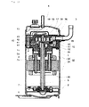
- Fig. 1 is a vertical sectional view of a compressor according to a first embodiment of the present invention.
- the compressor of the first embodiment includes a container 1 which is provided therein with a compressing mechanism 10 and an electric motor 20.
- the compressing mechanism 10 compresses refrigerant gas, and the electric motor 20 drives the compressing mechanism 10.
- An interior of the container 1 is divided into one of container spaces 31 and the other container space 32 by the compressing mechanism 10.
- the electric motor 20 is disposed in the other container space 32.
- the other container space 32 is divided into a compressing mechanism-side space 33 and an oil reserving-side space 34 by the electric motor 20.
- An oil reservoir 2 is disposed in the oil reserving-side space 34.
- a suction/connection pipe 3 and a discharge pipe 4 are fixed to the container 1 by welding.
- the suction/connection pipe 3 and the discharge pipe 4 are in communication with outside of the container 1, and are connected to members which configure a refrigeration cycle.
- the suction/connection pipe 3 introduces refrigerant gas from outside of the container 1, and the discharge pipe 4 discharges refrigerant gas to outside of the container 1 from the one container space 31.
- the main bearing member 11 is fixed in the container 1 by welding or shrink fitting, and the main bearing member 11 supports the shaft 5.
- a fixed scroll 12 is bolted to the main bearing member 11.
- An orbiting scroll 13 which meshes with the fixed scroll 12 is sandwiched between the main bearing member 11 and the fixed scroll 12.
- the main bearing member 11, the fixed scroll 12 and the orbiting scroll 13 configure the scroll-type compressing mechanism 10.
- a rotation-restraint mechanism 14 such as an Oldham ring is provided between the orbiting scroll 13 and the main bearing member 11.
- the rotation-restraint mechanism 14 prevents the orbiting scroll 13 from rotating, and guides the orbiting scroll 13 such that it circularly orbits.
- the orbiting scroll 13 is eccentrically driven by an eccentric shaft 5a provided on an upper end of the shaft 5.
- a compression chamber 15 formed between the fixed scroll 12 and the orbiting scroll 13 moves toward a central portion from an outer periphery, reduces its capacity, and compresses.
- a suction path 16 is formed between the suction/connection pipe 3 and the compression chamber 15.
- the suction path 16 is formed in the fixed scroll 12.
- a discharge port 17 of the compressing mechanism 10 is formed in a central portion of the fixed scroll 12.
- the discharge port 17 is provided with a reed valve 18.
- a muffler 19 which covers the discharge port 17 and the reed valve 18 is provided on the side of the one container space 31 of the fixed scroll 12. The muffler 19 separates the discharge port 17 away from the one container space 31.
- the refrigerant gas is sucked into the compression chamber 15 from the suction/connection pipe 3 through the suction path 16.
- Refrigerant gas compressed by the compression chamber 15 is discharged into the muffler 19 from the discharge port 17.
- the reed valve 18 is pushed and opened when the refrigerant gas is discharged from the discharge port 17.
- the shaft 5 is provided at its lower end with a pump 6.
- a suction port of the pump 6 is disposed in the oil reservoir 2 provided in a bottom of the container 1.
- the pump 6 is driven by the shaft 5. Therefore, the pump 6 can reliably pump up oil in the oil reservoir 2 irrespective of a pressure condition and a driving speed and therefore, lack of oil is not generated around a sliding portion.
- Oil pumped up by the pump 6 is supplied to the compressing mechanism 10 through an oil supply hole 7 formed in the shaft 5. If foreign substances are removed from oil using an oil filter before or after the oil is pumped up by the pump 6, it is possible to prevent the foreign substances from being mixed into the compressing mechanism 10, and the reliability can further be enhanced.
- Pressure of oil guided by the compressing mechanism 10 is substantially the same as discharge pressure of refrigerant gas discharged from the discharge port 17, and the pressure of the oil also becomes a back pressure source for the orbiting scroll 13.
- the orbiting scroll 13 is stably operated without separating from the fixed scroll 12 or without partially contacting with the fixed scroll 12.
- a portion of the oil enters and lubricates a fitting portion between the eccentric shaft 5a and the orbiting scroll 13, and a bearing portion 8 between the shaft 5 and the main bearing member 11 to seek for escape by supply pressure or weight of the oil itself and then, the oil drops and returns to the oil reservoir 2.
- a path 7a is formed in the orbiting scroll 13. One end of the path 7a opens at a high pressure region 35, and the other end of the path 7a opens at a back pressure chamber 36.
- the rotation-restraint mechanism 14 is disposed in the back pressure chamber 36.
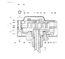
- Fig. 2 is an enlarged sectional view of essential portions of the compressing mechanism shown in Fig. 1 .
- the compressor of the embodiment includes the oil separating mechanism 40 which separates oil from refrigerant gas which is discharged from the compressing mechanism 10.
- the oil separating mechanism 40 includes a cylindrical space 41 in which the refrigerant gas orbits, an inflow portion 42 which brings an interior of the muffler 19 and the cylindrical space 41 into communication with each other, a sending-out port 43 which brings the cylindrical space 41 and the one container space 31 into communication with each other, and an exhaust port 44 which brings the cylindrical space 41 and the other container space 32 into communication with each other.
- the cylindrical space 41 includes a first cylindrical space 41a formed in the fixed scroll 12, and a second cylindrical space 41b formed in the main bearing member 11.
- the inflow portion 42 is in communication with the first cylindrical space 41a, and an opening of the inflow portion 42 is preferably formed in an inner peripheral surface of an upper end of the first cylindrical space 41a.
- the inflow portion 42 makes refrigerant gas which is discharged from the compressing mechanism 10 flow into the cylindrical space 41 from the muffler 19.
- the inflow portion 42 opens in a tangential direction with respect to the cylindrical space 41.
- the sending-out port 43 is formed on the side of an upper end of the cylindrical space 41, and is formed closer to the one container space 31 than at least the inflow portion 42.
- the sending-out port 43 is preferably formed in an upper end surface of the first cylindrical space 41a.
- the sending-out port 43 sends out, from the cylindrical space 41 to the one container space 31, refrigerant gas from which oil is separated.
- the exhaust port 44 is formed on the side of a lower end of the cylindrical space 41, and is formed closer to the other container space 32 than at least the inflow portion 42.
- the exhaust port 44 is preferably formed in a lower end surface of the second cylindrical space 41b.
- the exhaust port 44 discharges separated oil and a portion of refrigerant gas from the cylindrical space 41 into the compressing mechanism-side space 33.
- a cross-sectional area A of an opening of the sending-out port 43 is smaller than a cross-sectional area C of the cylindrical space 41 and is greater than a cross-sectional area B of an opening of the exhaust port 44. If the cross-sectional area A of the opening of the sending-out port 43 is the same as the cross-sectional area C of the cylindrical space 41, an orbiting flow of the refrigerant gas is blown out from the sending-out port 43 without being guided toward the exhaust port 44. If the cross-sectional area B of the opening of the exhaust port 44 is the same as the cross-sectional area C of the cylindrical space 41, the orbiting flow of the refrigerant gas is blown out from the exhaust port 44.
- cross-sectional area A of the opening of the sending-out port 43 is set greater than the cross-sectional area B of the opening of the exhaust port 44, a path resistance in the sending-out port 43 is reduced. According to this configuration, refrigerant gas easily flows to the sending-out port 43 as compared with the exhaust port 44.
- A/B can be set to about 9.
- a hole is formed in the outer periphery of the fixed scroll 12, thereby forming the first cylindrical space 41a, and a hole is formed in the outer periphery of the main bearing member 11, thereby forming the second cylindrical space 41b.
- a groove which opens in the tangential direction is formed in an end surface of the fixed scroll 12 on a side opposite from a lap with respect to the first cylindrical space 41a, a portion of the groove on the side of the first cylindrical space 41a is covered with the muffler 19, thereby configuring the inflow portion 42.
- the sending-out port 43 is formed in the muffler 19, and this hole is disposed in the opening of the first cylindrical space 41a.
- a hole formed in the bearing cover 45 configures the exhaust port 44, and this hole is disposed in the opening of the second cylindrical space 41b.
- Refrigerant gas discharged into the muffler 19 is guided to the cylindrical space 41 through the inflow portion 42 formed in the fixed scroll 12. Since the inflow portion 42 opens in the tangential direction with respect to the cylindrical space 41, refrigerant gas which is sent out from the inflow portion 42 flows along an inner wall surface of the cylindrical space 41, and an orbiting flow is generated around the inner peripheral surface of the cylindrical space 41. This orbiting flow becomes a flow moving toward the exhaust port 44.
- Oil supplied to the compressing mechanism 10 is included in the refrigerant gas. While the refrigerant gas is orbiting, oil having high specific gravity adheres to an inner wall of the cylindrical space 41 by a centrifugal force, and the oil separates from the refrigerant gas.
- the orbiting flow generated around the inner peripheral surface of the cylindrical space 41 turns up at the exhaust port 44, or in the vicinity of the exhaust port 44, and the orbiting flow is changed to an upward-moving stream which passes through the center of the cylindrical space 41.
- the refrigerant gas from which oil is separated by the centrifugal force reaches the sending-out port 43 by the upward-moving stream, and is sent out into the one container space 31.
- the refrigerant gas sent out into the container space 31 is sent to outside of the container 1 from the discharge pipe 4 provided in the one container space 31, and is supplied to the refrigeration cycle.
- Oil separated in the cylindrical space 41 is sent out from the exhaust port 44 into the compressing mechanism-side space 33 together with a small amount of refrigerant gas.
- the oil sent out into the compressing mechanism-side space 33 reaches the oil reservoir 2 through a wall surface of the container 1 or a communication path of the electric motor 20 by a weight of the oil itself.
- the refrigerant gas sent into the compressing mechanism-side space 33 passes through a gap of the compressing mechanism 10 and reaches the one container space 31, and is sent to outside of the container 1 from the discharge pipe 4.
- the sending-out port 43 is formed closer to the one container space 31 than the inflow portion 42, and the exhaust port 44 is formed closer to the other container space 32 than the inflow portion 42.
- the orbiting flow is generated around the inner peripheral surface of the cylindrical space 41 at a location from the inflow portion 42 to the exhaust port 44, and a flow in a direction opposite from the orbiting flow is generated around the center of the cylindrical space 41 at a location from the exhaust port 44 to the sending-out port 43. Therefore, as the exhaust port 44 separates from the inflow portion 42, the orbiting times of the refrigerant gas increase, and the oil separating effect is enhanced.
- the sending-out port 43 exists further from the discharge port than the inflow portion 42. That is, if a distance between the inflow portion 42 and the exhaust port 44 is increased as mush as possible, the oil orbiting separating effect can be enhanced.
- the oil separating mechanism 40 of the embodiment oil is discharged from the exhaust port 44 together with refrigerant gas without building up the separated oil in the container space 32. Therefore, the oil separating mechanism 40 has an effect of guiding the orbiting flow generated around the inner peripheral surface of the cylindrical space 41 in the direction of the exhaust port 44.
- most of high temperature and high pressure refrigerant gas which is compressed by the compressing mechanism 10 and sent out from the oil separating mechanism 40 is guided to the one container space 31 and is discharged from the discharge pipe 4. Therefore, most of the high temperature and high pressure refrigerant gas does not pass through the electric motor 20, the electric motor 20 is not heated by the refrigerant gas, and efficiency of the electric motor 20 is enhanced.
- the embodiment most of the high temperature and high pressure refrigerant gas is guided to the one container space 31, and it is possible to restrain the compressing mechanism 10 which is in contact with the other container space 32 from being heated. Hence, it is possible to restrain the sucked refrigerant gas from being heated, and to obtain high volumetric efficiency in the compression chamber.
- oil separated by the oil separating mechanism 40 is discharged into the other container space 32 together with the refrigerant gas.
- oil does not build up in the cylindrical space 41 almost at all. Therefore, the separated oil is not blown up in the cylindrical space 41 by the orbiting refrigerant gas, and the oil is not sent out from the sending-out port 43 together with the refrigerant gas, and oil is stably separated. Further, since oil does not build up in the cylindrical space 41, the cylindrical space 41 can be made compact.
- the oil reservoir 2 is disposed in the oil reserving-side space 34, and oil is not reserved in the compressing mechanism-side space 33.
- the container 1 can be made compact.
- the muffler 19 which isolates the discharge port 17 of the compressing mechanism 10 from the one container space 31 is disposed, the interior of the muffler 19 and the cylindrical space 41 are brought into communication with each other through the inflow portion 42, and refrigerant gas compressed by the compressing mechanism 10 can reliably be guided to the oil separating mechanism 40. That is, since all of refrigerant gas passes through the oil separating mechanism 40, it is possible to efficiently separate oil from refrigerant gas.
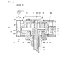
- Fig. 3 is an enlarged sectional view of essential portions of a compressing mechanism in a compressor according to a second embodiment of the invention.
- a first cylindrical space 41c and a sending-out port 43a are formed by forming a stepped-hole in an outer periphery of the fixed scroll 12.
- the first cylindrical space 41c is formed by forming a hole which does not penetrate an end surface (lap-side end surface) of the first cylindrical space 41c which is fastened to the main bearing member 11.
- the sending-out port 43a is formed by forming a hole smaller than a cross section of the first cylindrical space 41c which penetrates from an end surface (end surface on the side of lap) of the sending-out port 43a which is fastened to the main bearing member 11 or from an end surface (end surface opposite from lap) of the sending-out port 43a which is not fastened to the main bearing member 11.
- a second cylindrical space 41d and an exhaust port 44a are formed by forming a stepped-hole in an outer periphery of the main bearing member 11.
- the second cylindrical space 41d is formed by forming a hole which does not penetrate from a surface (thrust receiving surface) of the second cylindrical space 41d which is fastened to the fixed scroll 12.
- the exhaust port 44a is formed by forming a hole smaller than a cross section of the second cylindrical space 41d which penetrates from a surface (thrust surface) of the exhaust port 44a which is fastened to the fixed scroll 12, or from a surface (non-thrust surface) of the exhaust port 44a which is not fastened to the fixed scroll 12.
- the inflow portion 42a is formed by forming a through hole which opens in a tangential direction with respect to the first cylindrical space 41c from an end surface (end surface opposite from lap) of the fixed scroll 12 which is not fastened to the main bearing member 11.
- Fig. 4 is an enlarged sectional view of essential portions of a compressing mechanism in a compressor according to a third embodiment of the invention.
- a cylindrical sending-out pipe 46 is provided in the cylindrical space 41.
- One end 46a of the sending-out pipe 46 forms a sending-out port 43, and the other end 46b of the sending-out pipe 46 is disposed in the cylindrical space 41. In this embodiment, the other end 46b of the sending-out pipe 46 extends into the second cylindrical space 41b.
- a ring-shaped space 46c is formed in an outer periphery of the sending-out pipe 46, and the inflow portion 42 opens at the ring-shaped space 46c.
- An outwardly extending flange 46d is formed on the one end 46a of the sending-out pipe 46.
- Refrigerant gas which flows from the inflow portion 42 passes through the ring-shaped space 46c in a form of an orbiting flow, reaches the exhaust port 44 along the inner peripheral surface of the cylindrical space 41 and then, the refrigerant gas reversely flows through a center of the cylindrical space 41.
- the refrigerant gas flows into the sending-out pipe 46 from the other end 46b of the sending-out pipe 46, and flows out from the one end 46a of the sending-out pipe 46.
- a first cylindrical space 41e is formed by forming a stepped-hole in an outer periphery of the fixed scroll 12. That is, a hole greater than a cross section of an inner periphery of the first cylindrical space 41e is formed in an end surface of the fixed scroll 12 which is not on the side of the lap, and the flange 46d of the sending-out pipe 46 is accommodated in this hole.
- the second cylindrical space 41b is formed in the main bearing member 11, but the second cylindrical space 41b may be formed by forming a stepped-hole in the outer periphery of the main bearing member 11 as in the second embodiment.
- the sending-out pipe 46 When the sending-out pipe 46 is provided, it is important that the flange 46d is provided on the sending-out pipe 46, the flange 46d is disposed in a hole formed in the cylindrical space 41, and the sending-out pipe 46 is fixed to the cylindrical space 41 by the muffler 19.
- An inner diameter cross-sectional area D of the sending-out pipe 46 is set greater than a cross-sectional area B of the exhaust port 44. According to this configuration, refrigerant gas easily flows to the sending-out port 43 as compared with the exhaust port 44.
- the D/B can be set to about 9.
- the oil separating effect in the cylindrical space 41 can be enhanced.
- the basic operation of the oil separating mechanism 40 is the same as that of the first embodiment, and the third embodiment exerts the same operation and effect as those of the first embodiment. Therefore, explanation thereof will be omitted.
- Fig. 5 is an enlarged sectional view of essential portions of a compressing mechanism in a compressor according to a fourth embodiment of the invention.
- a cylindrical sending-out pipe 47 is provided in the cylindrical space 41.
- the sending-out pipe 47 of the embodiment is integrally formed with the muffler 19.
- One end 47a of the sending-out pipe 47 forms the sending-out port 43, and the other end 47b of the sending-out pipe 47 is disposed in the cylindrical space 41. In this embodiment, the other end 47b of the sending-out pipe 47 extends into the second cylindrical space 41b.
- a ring-shaped space 47c is formed in an outer periphery of the sending-out pipe 47, and the inflow portion 42 opens at the ring-shaped space 47c.
- Refrigerant gas which flows from the inflow portion 42 passes through the ring-shaped space 47c in a form of an orbiting flow, and reaches the exhaust port 44 along the inner peripheral surface of the cylindrical space 41 and then, reversely flows through a center of the cylindrical space 41.
- the refrigerant gas flows into the sending-out pipe 47 from the other end 47b of the sending-out pipe 47, and flows out from the one end 47a of the sending-out pipe 47.
- the sending-out pipe 47 can be fixed to the cylindrical space 41 by integrally forming the sending-out pipe 47 with the muffler 19.
- An inner diameter cross-sectional area D of the sending-out pipe 47 is set greater than a cross-sectional area B of the exhaust port 44.
- the oil separating effect in the cylindrical space 41 can be enhanced by providing the cylindrical sending-out pipe 47 in the cylindrical space 41.
- the basic operation of the oil separating mechanism 40 is the same as that of the first embodiment, and the fourth embodiment exerts the same operation and effect as those of the first embodiment. Therefore, explanation thereof will be omitted.
- the cylindrical space 41 includes the first cylindrical space 41a formed in the fixed scroll 12 and the second cylindrical space 41b formed in the main bearing member 11 like the first embodiment
- the second cylindrical space 41b may be formed by forming a stepped-hole in the outer periphery of the main bearing member 11 like the second embodiment.
- Fig. 6 is a vertical sectional view of a compressor according to a fifth embodiment of the invention.
- a refrigerant gas orbiting member 48 configuring the cylindrical space 41 is disposed in the one container space 31.
- the refrigerant gas orbiting member 48 is disposed on an outer peripheral surface of the muffler 19.
- the inflow portion 42b, a sending-out port 43b and an exhaust port 44b are formed in the refrigerant gas orbiting member 48.
- the inflow portion 42b brings an interior of the muffler 19 and the cylindrical space 41 into communication with each other.
- the sending-out port 43b brings the cylindrical space 41 and the one container space 31 into communication with each other.
- the exhaust port 44b brings the cylindrical space 41 and the one container space 31 into communication with each other.
- An opening of the inflow portion 42b is formed in an inner peripheral surface on the side of one end of the cylindrical space 41.
- the inflow portion 42b makes refrigerant gas discharged from the compressing mechanism 10 flow into the cylindrical space 41 from the muffler 19.
- the inflow portion 42b opens in the tangential direction with respect to the cylindrical space 41.
- the sending-out port 43b is formed on the side of the one end of the cylindrical space 41, and is formed closer to the one end than at least the inflow portion 42b. It is preferable that the sending-out port 43b is formed in an end surface on the side of the one end of the cylindrical space 41.
- the sending-out port 43b sends out, from the cylindrical space 41 to the one container space 31, refrigerant gas from which oil is separated.
- the exhaust port 44b is formed on the side of the other end of the cylindrical space 41, and is formed closer to the other end than at least the inflow portion 42b. It is preferable that the exhaust port 44b is formed in a lower portion of an end surface of the other end of the cylindrical space 41.
- the exhaust port 44b discharges the separated oil and a portion of refrigerant gas from the cylindrical space 41 into the one container space 31.
- a cross-sectional area A of an opening of the sending-out port 43b is smaller than a cross-sectional area C of the cylindrical space 41, and is greater than a cross-sectional area B of an opening of the exhaust port 44b.
- Refrigerant gas discharged into the muffler 19 is guided to the cylindrical space 41 through the inflow portion 42b formed in an upper surface of the muffler 19. Since the inflow portion 42b opens in the tangential direction with respect to the cylindrical space 41, refrigerant gas sent out from the inflow portion 42b flows along the inner wall surface of the cylindrical space 41, and an orbiting flow is generated around the inner peripheral surface of the cylindrical space 41. This orbiting flow becomes a flow moving toward the exhaust port 44b.
- Oil supplied to the compressing mechanism 10 is included in the refrigerant gas, and while the refrigerant gas is orbiting, oil having high specific gravity adheres to an inner wall of the cylindrical space 41 by the centrifugal force, and the oil separates from the refrigerant gas.
- the orbiting flow generated around the inner peripheral surface of the cylindrical space 41 turns up at the exhaust port 44b, or in the vicinity of the exhaust port 44b, the orbiting flow is changed to a reversed flow passing through a center of the cylindrical space 41.
- the refrigerant gas from which oil is separated by the centrifugal force reaches the sending-out port 43b by the flow passing through the center of the cylindrical space 41, and the refrigerant gas is sent out into the one container space 31.
- the refrigerant gas sent out into the one container space 31 is sent to outside of the container 1 from the discharge pipe 4 provided in the one container space 31, and is supplied to the refrigeration cycle.
- the oil separated in the cylindrical space 41 builds up such that the oil is deviated toward one side by its own weight. Since the exhaust port 44b is formed in a lower portion of the end surface on the side of the other end or in a lower portion of the cylindrical space 41, oil can easily be discharged out.
- the separated oil is sent out to an upper surface of the muffler 19 from the exhaust port 44b together with a small amount of refrigerant gas.
- the oil sent out to the upper surface of the muffler 19 passes through a gap in the compressing mechanism 10 by its own weight, reaches the compressing mechanism-side space 33 from the one container space 31, and reaches the oil reservoir 2 through a wall surface of the container 1 or a communication path of the electric motor 20.
- the refrigerant gas sent out from the exhaust port 44b is sent to outside of the container 1 from the discharge pipe 4 provided in the one container space 31, and is supplied to the refrigeration cycle.
- the sending-out port 43b is formed closer to the one end of the cylindrical space 41 than the inflow portion 42b, and the exhaust port 44b is formed closer to the other end of the cylindrical space 41 than the inflow portion 42b.
- an orbiting flow is generated around the inner peripheral surface of the cylindrical space 41 at a location from the inflow portion 42b to the exhaust port 44b, and a flow moving in a direction opposite from the orbiting flow is generated around a center portion of the cylindrical space 41 at a location from the exhaust port 44b to the sending-out port 43b. Therefore, as the exhaust port 44b separates away from the inflow portion 42b, the orbiting times of the refrigerant gas increase, and the oil separating effect is enhanced.
- the sending-out port 43b exists further from the exhaust port 44b than the inflow portion 42b. That is, if a distance between the inflow portion 42b and the exhaust port 44b is increased as mush as possible, the oil orbiting separating effect can be enhanced.
- the oil separating mechanism 40 of the embodiment oil is discharged from the exhaust port 44b together with refrigerant gas without building up the separated oil in the cylindrical space 41. Therefore, the oil separating mechanism 40 has an effect of guiding the orbiting flow generated around the inner peripheral surface of the cylindrical space 41 in the direction of the exhaust port 44b.
- the orbiting and separating motion can be carried out without changing a size of the compressor in its axial direction. Since the orbiting times of refrigerant gas increase, a distance of the cylindrical space 41, more specifically, a distance between the inflow portion 42b and the exhaust port 44b can be increased. According to this configuration, the oil separating mechanism 40 can be provided in the container 1 while maintaining the size of the compressor itself, and the oil orbiting and separating effect can also be enhanced.
- the path from the discharge port 17 to the discharge pipe 4 through which refrigerant gas flows can be shortened by disposing the refrigerant gas orbiting member 48 which configures the cylindrical space 41 in the one container space 31, and the container 1 can be made compact.
- high temperature and high pressure refrigerant gas which is compressed by the compressing mechanism 10 and which is sent out from the oil separating mechanism 40 is guided to the one container space 31, and is discharged from the discharge pipe 4. Therefore, since the high temperature and high pressure refrigerant gas does not pass through the electric motor 20, the electric motor 20 is not heated by the refrigerant gas, and the efficiency of the electric motor 20 is enhanced.
- the embodiment by guiding the high temperature and high pressure refrigerant gas to the one container space 31, it is possible to restrain the compressing mechanism 10 which is in contact with the other container space 32 from being heated. Therefore, it is possible to restrain the sucked refrigerant gas from being heated, and to obtain high volumetric efficiency in the compression chamber.
- oil separated by the oil separating mechanism 40 is discharged into the one container space 31 together with the refrigerant gas.
- oil does not build up in the cylindrical space 41 almost at all. Therefore, the separated oil is not blown up in the cylindrical space 41 by the orbiting refrigerant gas, and the oil is not sent out from the sending-out port 43b together with the refrigerant gas, and oil is stably separated. Further, since oil does not build up in the cylindrical space 41, the cylindrical space 41 can be made compact.
- the oil reservoir 2 is disposed in the oil reserving-side space 34, and oil does not build up in the compressing mechanism-side space 33. Hence, the container 1 can be made compact.
- the muffler 19 which isolates the discharge port 17 of the compressing mechanism 10 from the one container space 31 is disposed, the interior of the muffler 19 and the cylindrical space 41 are brought into communication with each other through the inflow portion 42b, and refrigerant gas compressed by the compressing mechanism 10 can reliably be guided to the oil separating mechanism 40. That is, since all of refrigerant gas passes through the oil separating mechanism 40, it is possible to efficiently separate oil from refrigerant gas.
- the high temperature refrigerant gas discharged from the discharge port 17 is discharged outside of the container 1 from the discharge pipe 4 without passing through the other container space 32. Therefore, it is possible to restrain the electric motor 20 and the compressing mechanism 10 from being heated.
- two or more cylindrical spaces 41 may be provided.
- carbon dioxide can be used as refrigerant.
- Carbon dioxide is high temperature refrigerant, and when such high temperature refrigerant is used, the present invention is further effective.
- oil including polyalkylene glycol (PAG) as main ingredient is used. Since compatibility between carbon dioxide and polyalkylene glycol is low, the oil separating effect is high.
- PAG polyalkylene glycol
- the present invention can be applied to a compressor having a compressing mechanism and an electric motor in a container such as a scroll compressor and a rotary compressor.
- the invention is suitable for a compressor using high temperature refrigerant.
Landscapes
- Engineering & Computer Science (AREA)
- Mechanical Engineering (AREA)
- General Engineering & Computer Science (AREA)
- Applications Or Details Of Rotary Compressors (AREA)
- Rotary Pumps (AREA)
- Compressor (AREA)
Applications Claiming Priority (2)
| Application Number | Priority Date | Filing Date | Title |
|---|---|---|---|
| JP2011059986 | 2011-03-18 | ||
| PCT/JP2012/001819 WO2012127825A1 (fr) | 2011-03-18 | 2012-03-15 | Compresseur |
Publications (3)
| Publication Number | Publication Date |
|---|---|
| EP2687726A4 EP2687726A4 (fr) | 2014-01-22 |
| EP2687726A1 true EP2687726A1 (fr) | 2014-01-22 |
| EP2687726B1 EP2687726B1 (fr) | 2014-11-05 |
Family
ID=46879005
Family Applications (1)
| Application Number | Title | Priority Date | Filing Date |
|---|---|---|---|
| EP12760618.4A Active EP2687726B1 (fr) | 2011-03-18 | 2012-03-15 | Compresseur |
Country Status (5)
| Country | Link |
|---|---|
| US (1) | US9109598B2 (fr) |
| EP (1) | EP2687726B1 (fr) |
| JP (2) | JP5255157B2 (fr) |
| CN (1) | CN103052804B (fr) |
| WO (1) | WO2012127825A1 (fr) |
Families Citing this family (13)
| Publication number | Priority date | Publication date | Assignee | Title |
|---|---|---|---|---|
| US8814537B2 (en) | 2011-09-30 | 2014-08-26 | Emerson Climate Technologies, Inc. | Direct-suction compressor |
| JP5938560B2 (ja) * | 2012-06-06 | 2016-06-22 | パナソニックIpマネジメント株式会社 | 圧縮機 |
| US9366462B2 (en) | 2012-09-13 | 2016-06-14 | Emerson Climate Technologies, Inc. | Compressor assembly with directed suction |
| CN103967799B (zh) * | 2013-01-24 | 2017-02-08 | 珠海格力节能环保制冷技术研究中心有限公司 | 制冷压缩机及其降低排气含油率的方法 |
| JP6134906B2 (ja) * | 2013-04-16 | 2017-05-31 | パナソニックIpマネジメント株式会社 | 圧縮機 |
| JP2018035800A (ja) * | 2016-09-02 | 2018-03-08 | 日立ジョンソンコントロールズ空調株式会社 | 密閉型電動圧縮機、及び、冷凍機器 |
| JPWO2019044349A1 (ja) * | 2017-09-04 | 2020-10-01 | パナソニックIpマネジメント株式会社 | 圧縮機 |
| US11236748B2 (en) | 2019-03-29 | 2022-02-01 | Emerson Climate Technologies, Inc. | Compressor having directed suction |
| US11767838B2 (en) | 2019-06-14 | 2023-09-26 | Copeland Lp | Compressor having suction fitting |
| US11248605B1 (en) | 2020-07-28 | 2022-02-15 | Emerson Climate Technologies, Inc. | Compressor having shell fitting |
| KR102409626B1 (ko) * | 2020-08-19 | 2022-06-16 | 엘지전자 주식회사 | 스크롤 압축기 |
| US11619228B2 (en) | 2021-01-27 | 2023-04-04 | Emerson Climate Technologies, Inc. | Compressor having directed suction |
| US12180966B2 (en) | 2022-12-22 | 2024-12-31 | Copeland Lp | Compressor with funnel assembly |
Family Cites Families (31)
| Publication number | Priority date | Publication date | Assignee | Title |
|---|---|---|---|---|
| US4596521A (en) * | 1982-12-17 | 1986-06-24 | Hitachi, Ltd. | Scroll fluid apparatus |
| JPS6073080A (ja) * | 1983-09-30 | 1985-04-25 | Toshiba Corp | スクロ−ル型圧縮装置 |
| JPS6075797A (ja) | 1983-10-03 | 1985-04-30 | Hitachi Ltd | 空調機用圧縮機 |
| JPS62203992A (ja) * | 1986-03-03 | 1987-09-08 | Hitachi Ltd | 密閉形スクロ−ル圧縮機 |
| JPH0544667A (ja) | 1991-08-09 | 1993-02-23 | Hitachi Ltd | 密閉形スクロール圧縮機 |
| JP2871307B2 (ja) | 1992-06-30 | 1999-03-17 | ダイキン工業株式会社 | スクロール圧縮機 |
| US5591018A (en) * | 1993-12-28 | 1997-01-07 | Matsushita Electric Industrial Co., Ltd. | Hermetic scroll compressor having a pumped fluid motor cooling means and an oil collection pan |
| JPH08326676A (ja) * | 1995-06-05 | 1996-12-10 | Matsushita Electric Ind Co Ltd | 冷凍機用圧縮機 |
| JPH1193880A (ja) | 1997-09-16 | 1999-04-06 | Denso Corp | 圧縮機 |
| JP4103225B2 (ja) * | 1998-06-24 | 2008-06-18 | 株式会社日本自動車部品総合研究所 | 圧縮機 |
| CN100494678C (zh) | 2002-03-12 | 2009-06-03 | 松下电器产业株式会社 | 压缩机 |
| JP2003269336A (ja) * | 2002-03-14 | 2003-09-25 | Denso Corp | 圧縮機及び油分離器 |
| JP3832369B2 (ja) * | 2002-03-28 | 2006-10-11 | ダイキン工業株式会社 | 高低圧ドーム型圧縮機 |
| KR100924895B1 (ko) * | 2002-05-24 | 2009-11-02 | 파나소닉 주식회사 | 스크롤 압축기 |
| JP4024723B2 (ja) | 2002-07-04 | 2007-12-19 | 株式会社デンソー | ハイブリッドコンプレッサ |
| JP3838174B2 (ja) | 2002-07-31 | 2006-10-25 | 株式会社デンソー | 電動圧縮機 |
| JP4440564B2 (ja) * | 2003-06-12 | 2010-03-24 | パナソニック株式会社 | スクロール圧縮機 |
| JP4376554B2 (ja) * | 2003-06-12 | 2009-12-02 | パナソニック株式会社 | スクロール圧縮機 |
| ATE478261T1 (de) * | 2003-09-30 | 2010-09-15 | Sanyo Electric Co | Rotationsverdichter, klimaanlage für ein fahrzeug und wassererhitzer, die den verdichter beinhalten |
| JP2005105986A (ja) | 2003-09-30 | 2005-04-21 | Sanyo Electric Co Ltd | 縦型ロータリコンプレッサ |
| JP2005180295A (ja) | 2003-12-19 | 2005-07-07 | Mitsubishi Heavy Ind Ltd | スクロール圧縮機 |
| JP2006090180A (ja) * | 2004-09-22 | 2006-04-06 | Matsushita Electric Ind Co Ltd | 密閉型圧縮機 |
| JP2006342722A (ja) | 2005-06-09 | 2006-12-21 | Mitsubishi Heavy Ind Ltd | 圧縮機 |
| KR100772218B1 (ko) * | 2005-12-12 | 2007-11-01 | 엘지전자 주식회사 | 스크롤 압축기 |
| JP4872798B2 (ja) | 2006-05-29 | 2012-02-08 | 株式会社デンソー | 圧縮機 |
| JP2008088929A (ja) | 2006-10-04 | 2008-04-17 | Sanden Corp | 密閉型圧縮機 |
| EP2113053B1 (fr) * | 2007-01-15 | 2015-08-19 | LG Electronics Inc. | Compresseur et dispositif de séparation d'huile pour celui-ci |
| JP4595943B2 (ja) | 2007-01-16 | 2010-12-08 | 三菱電機株式会社 | 圧縮機 |
| US8037712B2 (en) | 2008-10-28 | 2011-10-18 | Lg Electronics Inc. | Hermetic compressor and refrigeration cycle having the same |
| JP5516607B2 (ja) * | 2010-01-27 | 2014-06-11 | ダイキン工業株式会社 | 圧縮機及び冷凍装置 |
| JP5447140B2 (ja) | 2010-04-23 | 2014-03-19 | 株式会社デンソー | 圧縮機 |
-
2012
- 2012-03-15 JP JP2012529993A patent/JP5255157B2/ja active Active
- 2012-03-15 EP EP12760618.4A patent/EP2687726B1/fr active Active
- 2012-03-15 US US13/812,347 patent/US9109598B2/en active Active
- 2012-03-15 CN CN201280002269.2A patent/CN103052804B/zh active Active
- 2012-03-15 WO PCT/JP2012/001819 patent/WO2012127825A1/fr not_active Ceased
-
2013
- 2013-03-06 JP JP2013043652A patent/JP2013137030A/ja active Pending
Also Published As
| Publication number | Publication date |
|---|---|
| US20130129549A1 (en) | 2013-05-23 |
| EP2687726B1 (fr) | 2014-11-05 |
| JP5255157B2 (ja) | 2013-08-07 |
| EP2687726A4 (fr) | 2014-01-22 |
| US9109598B2 (en) | 2015-08-18 |
| JP2013137030A (ja) | 2013-07-11 |
| WO2012127825A1 (fr) | 2012-09-27 |
| JPWO2012127825A1 (ja) | 2014-07-24 |
| CN103052804B (zh) | 2016-01-20 |
| CN103052804A (zh) | 2013-04-17 |
Similar Documents
| Publication | Publication Date | Title |
|---|---|---|
| US9109598B2 (en) | Compressor with oil separating mechanism | |
| US9284955B2 (en) | Compressor | |
| CN103075323B (zh) | 压缩机 | |
| JP5609770B2 (ja) | 圧縮機 | |
| CN103534487B (zh) | 压缩机 | |
| JP6108276B2 (ja) | 圧縮機 | |
| CN103782033B (zh) | 压缩机 | |
| CN103635694B (zh) | 压缩机 | |
| CN103362817B (zh) | 压缩机 | |
| JP2013213478A (ja) | 圧縮機 | |
| CN103797249B (zh) | 压缩机 | |
| WO2012127547A1 (fr) | Compresseur | |
| JP6120173B2 (ja) | 圧縮機 | |
| JP5934912B2 (ja) | 圧縮機 | |
| JP2013096352A (ja) | 圧縮機 | |
| JP2013253514A (ja) | 圧縮機 |
Legal Events
| Date | Code | Title | Description |
|---|---|---|---|
| PUAI | Public reference made under article 153(3) epc to a published international application that has entered the european phase |
Free format text: ORIGINAL CODE: 0009012 |
|
| 17P | Request for examination filed |
Effective date: 20131018 |
|
| A4 | Supplementary search report drawn up and despatched |
Effective date: 20131217 |
|
| AK | Designated contracting states |
Kind code of ref document: A1 Designated state(s): AL AT BE BG CH CY CZ DE DK EE ES FI FR GB GR HR HU IE IS IT LI LT LU LV MC MK MT NL NO PL PT RO RS SE SI SK SM TR |
|
| DAX | Request for extension of the european patent (deleted) | ||
| RIC1 | Information provided on ipc code assigned before grant |
Ipc: F04C 29/02 20060101AFI20140522BHEP Ipc: F04C 23/00 20060101ALN20140522BHEP Ipc: F04B 39/04 20060101ALI20140522BHEP Ipc: F04C 18/02 20060101ALI20140522BHEP |
|
| GRAP | Despatch of communication of intention to grant a patent |
Free format text: ORIGINAL CODE: EPIDOSNIGR1 |
|
| INTG | Intention to grant announced |
Effective date: 20140630 |
|
| GRAS | Grant fee paid |
Free format text: ORIGINAL CODE: EPIDOSNIGR3 |
|
| GRAA | (expected) grant |
Free format text: ORIGINAL CODE: 0009210 |
|
| AK | Designated contracting states |
Kind code of ref document: B1 Designated state(s): AL AT BE BG CH CY CZ DE DK EE ES FI FR GB GR HR HU IE IS IT LI LT LU LV MC MK MT NL NO PL PT RO RS SE SI SK SM TR |
|
| REG | Reference to a national code |
Ref country code: GB Ref legal event code: FG4D |
|
| REG | Reference to a national code |
Ref country code: CH Ref legal event code: EP |
|
| REG | Reference to a national code |
Ref country code: AT Ref legal event code: REF Ref document number: 694801 Country of ref document: AT Kind code of ref document: T Effective date: 20141115 |
|
| REG | Reference to a national code |
Ref country code: IE Ref legal event code: FG4D |
|
| REG | Reference to a national code |
Ref country code: DE Ref legal event code: R096 Ref document number: 602012003697 Country of ref document: DE Effective date: 20141224 |
|
| REG | Reference to a national code |
Ref country code: AT Ref legal event code: MK05 Ref document number: 694801 Country of ref document: AT Kind code of ref document: T Effective date: 20141105 |
|
| REG | Reference to a national code |
Ref country code: NL Ref legal event code: VDEP Effective date: 20141105 |
|
| REG | Reference to a national code |
Ref country code: LT Ref legal event code: MG4D |
|
| PG25 | Lapsed in a contracting state [announced via postgrant information from national office to epo] |
Ref country code: NO Free format text: LAPSE BECAUSE OF FAILURE TO SUBMIT A TRANSLATION OF THE DESCRIPTION OR TO PAY THE FEE WITHIN THE PRESCRIBED TIME-LIMIT Effective date: 20150205 Ref country code: LT Free format text: LAPSE BECAUSE OF FAILURE TO SUBMIT A TRANSLATION OF THE DESCRIPTION OR TO PAY THE FEE WITHIN THE PRESCRIBED TIME-LIMIT Effective date: 20141105 Ref country code: PT Free format text: LAPSE BECAUSE OF FAILURE TO SUBMIT A TRANSLATION OF THE DESCRIPTION OR TO PAY THE FEE WITHIN THE PRESCRIBED TIME-LIMIT Effective date: 20150305 Ref country code: IS Free format text: LAPSE BECAUSE OF FAILURE TO SUBMIT A TRANSLATION OF THE DESCRIPTION OR TO PAY THE FEE WITHIN THE PRESCRIBED TIME-LIMIT Effective date: 20150305 Ref country code: NL Free format text: LAPSE BECAUSE OF FAILURE TO SUBMIT A TRANSLATION OF THE DESCRIPTION OR TO PAY THE FEE WITHIN THE PRESCRIBED TIME-LIMIT Effective date: 20141105 Ref country code: ES Free format text: LAPSE BECAUSE OF FAILURE TO SUBMIT A TRANSLATION OF THE DESCRIPTION OR TO PAY THE FEE WITHIN THE PRESCRIBED TIME-LIMIT Effective date: 20141105 Ref country code: FI Free format text: LAPSE BECAUSE OF FAILURE TO SUBMIT A TRANSLATION OF THE DESCRIPTION OR TO PAY THE FEE WITHIN THE PRESCRIBED TIME-LIMIT Effective date: 20141105 |
|
| PG25 | Lapsed in a contracting state [announced via postgrant information from national office to epo] |
Ref country code: HR Free format text: LAPSE BECAUSE OF FAILURE TO SUBMIT A TRANSLATION OF THE DESCRIPTION OR TO PAY THE FEE WITHIN THE PRESCRIBED TIME-LIMIT Effective date: 20141105 Ref country code: GR Free format text: LAPSE BECAUSE OF FAILURE TO SUBMIT A TRANSLATION OF THE DESCRIPTION OR TO PAY THE FEE WITHIN THE PRESCRIBED TIME-LIMIT Effective date: 20150206 Ref country code: LV Free format text: LAPSE BECAUSE OF FAILURE TO SUBMIT A TRANSLATION OF THE DESCRIPTION OR TO PAY THE FEE WITHIN THE PRESCRIBED TIME-LIMIT Effective date: 20141105 Ref country code: PL Free format text: LAPSE BECAUSE OF FAILURE TO SUBMIT A TRANSLATION OF THE DESCRIPTION OR TO PAY THE FEE WITHIN THE PRESCRIBED TIME-LIMIT Effective date: 20141105 Ref country code: RS Free format text: LAPSE BECAUSE OF FAILURE TO SUBMIT A TRANSLATION OF THE DESCRIPTION OR TO PAY THE FEE WITHIN THE PRESCRIBED TIME-LIMIT Effective date: 20141105 Ref country code: AT Free format text: LAPSE BECAUSE OF FAILURE TO SUBMIT A TRANSLATION OF THE DESCRIPTION OR TO PAY THE FEE WITHIN THE PRESCRIBED TIME-LIMIT Effective date: 20141105 Ref country code: CY Free format text: LAPSE BECAUSE OF FAILURE TO SUBMIT A TRANSLATION OF THE DESCRIPTION OR TO PAY THE FEE WITHIN THE PRESCRIBED TIME-LIMIT Effective date: 20141105 Ref country code: SE Free format text: LAPSE BECAUSE OF FAILURE TO SUBMIT A TRANSLATION OF THE DESCRIPTION OR TO PAY THE FEE WITHIN THE PRESCRIBED TIME-LIMIT Effective date: 20141105 |
|
| PG25 | Lapsed in a contracting state [announced via postgrant information from national office to epo] |
Ref country code: EE Free format text: LAPSE BECAUSE OF FAILURE TO SUBMIT A TRANSLATION OF THE DESCRIPTION OR TO PAY THE FEE WITHIN THE PRESCRIBED TIME-LIMIT Effective date: 20141105 Ref country code: CZ Free format text: LAPSE BECAUSE OF FAILURE TO SUBMIT A TRANSLATION OF THE DESCRIPTION OR TO PAY THE FEE WITHIN THE PRESCRIBED TIME-LIMIT Effective date: 20141105 Ref country code: DK Free format text: LAPSE BECAUSE OF FAILURE TO SUBMIT A TRANSLATION OF THE DESCRIPTION OR TO PAY THE FEE WITHIN THE PRESCRIBED TIME-LIMIT Effective date: 20141105 Ref country code: SK Free format text: LAPSE BECAUSE OF FAILURE TO SUBMIT A TRANSLATION OF THE DESCRIPTION OR TO PAY THE FEE WITHIN THE PRESCRIBED TIME-LIMIT Effective date: 20141105 |
|
| REG | Reference to a national code |
Ref country code: DE Ref legal event code: R097 Ref document number: 602012003697 Country of ref document: DE |
|
| PLBE | No opposition filed within time limit |
Free format text: ORIGINAL CODE: 0009261 |
|
| STAA | Information on the status of an ep patent application or granted ep patent |
Free format text: STATUS: NO OPPOSITION FILED WITHIN TIME LIMIT |
|
| 26N | No opposition filed |
Effective date: 20150806 |
|
| PG25 | Lapsed in a contracting state [announced via postgrant information from national office to epo] |
Ref country code: MC Free format text: LAPSE BECAUSE OF FAILURE TO SUBMIT A TRANSLATION OF THE DESCRIPTION OR TO PAY THE FEE WITHIN THE PRESCRIBED TIME-LIMIT Effective date: 20141105 Ref country code: LU Free format text: LAPSE BECAUSE OF FAILURE TO SUBMIT A TRANSLATION OF THE DESCRIPTION OR TO PAY THE FEE WITHIN THE PRESCRIBED TIME-LIMIT Effective date: 20150315 |
|
| REG | Reference to a national code |
Ref country code: CH Ref legal event code: PL |
|
| PG25 | Lapsed in a contracting state [announced via postgrant information from national office to epo] |
Ref country code: IT Free format text: LAPSE BECAUSE OF FAILURE TO SUBMIT A TRANSLATION OF THE DESCRIPTION OR TO PAY THE FEE WITHIN THE PRESCRIBED TIME-LIMIT Effective date: 20141105 |
|
| REG | Reference to a national code |
Ref country code: IE Ref legal event code: MM4A |
|
| PG25 | Lapsed in a contracting state [announced via postgrant information from national office to epo] |
Ref country code: LI Free format text: LAPSE BECAUSE OF NON-PAYMENT OF DUE FEES Effective date: 20150331 Ref country code: CH Free format text: LAPSE BECAUSE OF NON-PAYMENT OF DUE FEES Effective date: 20150331 Ref country code: IE Free format text: LAPSE BECAUSE OF NON-PAYMENT OF DUE FEES Effective date: 20150315 |
|
| PG25 | Lapsed in a contracting state [announced via postgrant information from national office to epo] |
Ref country code: SI Free format text: LAPSE BECAUSE OF FAILURE TO SUBMIT A TRANSLATION OF THE DESCRIPTION OR TO PAY THE FEE WITHIN THE PRESCRIBED TIME-LIMIT Effective date: 20141105 |
|
| REG | Reference to a national code |
Ref country code: FR Ref legal event code: PLFP Year of fee payment: 5 |
|
| PG25 | Lapsed in a contracting state [announced via postgrant information from national office to epo] |
Ref country code: RO Free format text: LAPSE BECAUSE OF FAILURE TO SUBMIT A TRANSLATION OF THE DESCRIPTION OR TO PAY THE FEE WITHIN THE PRESCRIBED TIME-LIMIT Effective date: 20141105 |
|
| GBPC | Gb: european patent ceased through non-payment of renewal fee |
Effective date: 20160315 |
|
| PG25 | Lapsed in a contracting state [announced via postgrant information from national office to epo] |
Ref country code: MT Free format text: LAPSE BECAUSE OF FAILURE TO SUBMIT A TRANSLATION OF THE DESCRIPTION OR TO PAY THE FEE WITHIN THE PRESCRIBED TIME-LIMIT Effective date: 20141105 |
|
| PG25 | Lapsed in a contracting state [announced via postgrant information from national office to epo] |
Ref country code: GB Free format text: LAPSE BECAUSE OF NON-PAYMENT OF DUE FEES Effective date: 20160315 |
|
| REG | Reference to a national code |
Ref country code: FR Ref legal event code: PLFP Year of fee payment: 6 |
|
| PG25 | Lapsed in a contracting state [announced via postgrant information from national office to epo] |
Ref country code: SM Free format text: LAPSE BECAUSE OF FAILURE TO SUBMIT A TRANSLATION OF THE DESCRIPTION OR TO PAY THE FEE WITHIN THE PRESCRIBED TIME-LIMIT Effective date: 20141105 Ref country code: HU Free format text: LAPSE BECAUSE OF FAILURE TO SUBMIT A TRANSLATION OF THE DESCRIPTION OR TO PAY THE FEE WITHIN THE PRESCRIBED TIME-LIMIT; INVALID AB INITIO Effective date: 20120315 Ref country code: BG Free format text: LAPSE BECAUSE OF FAILURE TO SUBMIT A TRANSLATION OF THE DESCRIPTION OR TO PAY THE FEE WITHIN THE PRESCRIBED TIME-LIMIT Effective date: 20141105 |
|
| PG25 | Lapsed in a contracting state [announced via postgrant information from national office to epo] |
Ref country code: TR Free format text: LAPSE BECAUSE OF FAILURE TO SUBMIT A TRANSLATION OF THE DESCRIPTION OR TO PAY THE FEE WITHIN THE PRESCRIBED TIME-LIMIT Effective date: 20141105 |
|
| PG25 | Lapsed in a contracting state [announced via postgrant information from national office to epo] |
Ref country code: BE Free format text: LAPSE BECAUSE OF FAILURE TO SUBMIT A TRANSLATION OF THE DESCRIPTION OR TO PAY THE FEE WITHIN THE PRESCRIBED TIME-LIMIT Effective date: 20141105 |
|
| REG | Reference to a national code |
Ref country code: FR Ref legal event code: PLFP Year of fee payment: 7 |
|
| PG25 | Lapsed in a contracting state [announced via postgrant information from national office to epo] |
Ref country code: MK Free format text: LAPSE BECAUSE OF FAILURE TO SUBMIT A TRANSLATION OF THE DESCRIPTION OR TO PAY THE FEE WITHIN THE PRESCRIBED TIME-LIMIT Effective date: 20141105 |
|
| PG25 | Lapsed in a contracting state [announced via postgrant information from national office to epo] |
Ref country code: AL Free format text: LAPSE BECAUSE OF FAILURE TO SUBMIT A TRANSLATION OF THE DESCRIPTION OR TO PAY THE FEE WITHIN THE PRESCRIBED TIME-LIMIT Effective date: 20141105 |
|
| PGFP | Annual fee paid to national office [announced via postgrant information from national office to epo] |
Ref country code: DE Payment date: 20260319 Year of fee payment: 15 |
|
| PGFP | Annual fee paid to national office [announced via postgrant information from national office to epo] |
Ref country code: FR Payment date: 20260320 Year of fee payment: 15 |