EP2689900A1 - Procédé d'entraînement pour dispositif d'articulation - Google Patents
Procédé d'entraînement pour dispositif d'articulation Download PDFInfo
- Publication number
- EP2689900A1 EP2689900A1 EP11852221.8A EP11852221A EP2689900A1 EP 2689900 A1 EP2689900 A1 EP 2689900A1 EP 11852221 A EP11852221 A EP 11852221A EP 2689900 A1 EP2689900 A1 EP 2689900A1
- Authority
- EP
- European Patent Office
- Prior art keywords
- gear
- motor
- link
- speed reducer
- differential speed
- Prior art date
- Legal status (The legal status is an assumption and is not a legal conclusion. Google has not performed a legal analysis and makes no representation as to the accuracy of the status listed.)
- Granted
Links
Images




Classifications
-
- B—PERFORMING OPERATIONS; TRANSPORTING
- B25—HAND TOOLS; PORTABLE POWER-DRIVEN TOOLS; MANIPULATORS
- B25J—MANIPULATORS; CHAMBERS PROVIDED WITH MANIPULATION DEVICES
- B25J9/00—Program-controlled manipulators
- B25J9/10—Program-controlled manipulators characterised by positioning means for manipulator elements
- B25J9/102—Gears specially adapted therefor, e.g. reduction gears
- B25J9/1025—Harmonic drives
-
- B—PERFORMING OPERATIONS; TRANSPORTING
- B25—HAND TOOLS; PORTABLE POWER-DRIVEN TOOLS; MANIPULATORS
- B25J—MANIPULATORS; CHAMBERS PROVIDED WITH MANIPULATION DEVICES
- B25J17/00—Joints
-
- F—MECHANICAL ENGINEERING; LIGHTING; HEATING; WEAPONS; BLASTING
- F16—ENGINEERING ELEMENTS AND UNITS; GENERAL MEASURES FOR PRODUCING AND MAINTAINING EFFECTIVE FUNCTIONING OF MACHINES OR INSTALLATIONS; THERMAL INSULATION IN GENERAL
- F16H—GEARING
- F16H49/00—Other gearings
- F16H49/001—Wave gearings, e.g. harmonic drive transmissions
-
- Y—GENERAL TAGGING OF NEW TECHNOLOGICAL DEVELOPMENTS; GENERAL TAGGING OF CROSS-SECTIONAL TECHNOLOGIES SPANNING OVER SEVERAL SECTIONS OF THE IPC; TECHNICAL SUBJECTS COVERED BY FORMER USPC CROSS-REFERENCE ART COLLECTIONS [XRACs] AND DIGESTS
- Y10—TECHNICAL SUBJECTS COVERED BY FORMER USPC
- Y10T—TECHNICAL SUBJECTS COVERED BY FORMER US CLASSIFICATION
- Y10T74/00—Machine element or mechanism
- Y10T74/19—Gearing
-
- Y—GENERAL TAGGING OF NEW TECHNOLOGICAL DEVELOPMENTS; GENERAL TAGGING OF CROSS-SECTIONAL TECHNOLOGIES SPANNING OVER SEVERAL SECTIONS OF THE IPC; TECHNICAL SUBJECTS COVERED BY FORMER USPC CROSS-REFERENCE ART COLLECTIONS [XRACs] AND DIGESTS
- Y10—TECHNICAL SUBJECTS COVERED BY FORMER USPC
- Y10T—TECHNICAL SUBJECTS COVERED BY FORMER US CLASSIFICATION
- Y10T74/00—Machine element or mechanism
- Y10T74/20—Control lever and linkage systems
- Y10T74/20207—Multiple controlling elements for single controlled element
- Y10T74/20305—Robotic arm
- Y10T74/20317—Robotic arm including electric motor
Definitions
- the present invention relates to a robot joint device and a method of controlling drive of a joint unit of a robot. More specifically, the present invention relates to a robot joint device having flexibility (back drivability) with respect to external force, and a method of controlling drive of a robot joint unit having flexibility (back drivability) with respect to external force.
- Service robots are required to have light weight, high torque capability, and perform operation control with high accuracy. From these points of views, the combination of a servo motor and a differential speed reducer has been adopted in the joint unit of almost all the service robots.
- the differential speed reducer has compactness, light weight, high accuracy, and high reduction ratios, and is the element indispensable for driving joints of a service robot. While such a differential speed reducer is able to achieve driving with high accuracy with no backlash in a compact space, its back drivability is extremely low. In particular, in a state in which the joints are stopped, a large static friction acts on mesh of gears in the differential speed reducer. Accordingly, unless extremely large torque is applied from an output side, it is impossible to rotate the joint from the output side against the static friction in the differential speed reducer.
- a friction model is disclosed in a non-patent literature 1, for example.
- Fig. 11 shows this friction model. Although there are many other friction models, the basic pattern is substantially the same.
- a problem raised when dithering is performed is that hands or fingers subtly oscillate. Further, a problem caused when the motor is oscillatory moved is that the life of mechanism components such as a speed reducer is dramatically decreased. Furthermore, a problem raised when the motor is oscillatory moved is that noise is occurred due to the oscillation.
- the present invention aims to provide a joint device which is suitable for a robot joint and has improved back drivability, and a method of driving the same.
- a method of driving a joint device is a method of driving a joint device including a drive unit and a differential speed reducer provided between a first link and a second link, the joint device controlling drive of the first link and the second link as joints, in which the differential speed reducer includes an internal gear, an intermediate gear, and an external gear, and the drive unit includes a first motor and a second motor, the method including: fixedly connecting the first motor and the second motor to the first link; coupling an output shaft of the first motor to one of the internal gear, the intermediate gear, and the external gear of the differential speed reducer; coupling an output shaft of the second motor to one of the internal gear, the intermediate gear, and the external gear of the differential speed reducer which is different from the gear coupled to the output shaft of the first motor; and coupling to the second link one of gears of the internal gear, the intermediate gear, and the external gear of the differential speed reducer which is different from the gear coupled to the output shaft of the first motor; and coupling to the second link one of gears of the internal gear, the intermediate
- the differential speed reducer is preferably a harmonic drive gear mechanism or a planetary gear mechanism.
- a relation between a friction force and a relative speed difference among the internal gear, the intermediate gear, and the external gear as a friction model in the differential speed reducer, and determine a rotational speed in each of the first motor and the second motor so as to approach a speed difference to minimize the friction with a rotational speed ratio which can achieve joint stop.
- a joint device is a joint device including a differential speed reducer provided between a first link and a second link and driving joints of the first link and the second link, the joint device including:
- such a state can be achieved in which gears in the differential speed reducer relatively move while the joint stops the motion.
- such a state can be achieved in which static friction does not act in the differential speed reducer even when the joint stops motion. Accordingly, the friction in the differential speed reducer becomes small, whereby high back drivability can be secured.
- a robot joint device will now be described. A structure and an operation of a differential speed reducer used for the robot joint device will be described before describing a structure of the present invention.
- a harmonic drive gear known as a harmonic drive will be described as an example of the differential speed reducer.
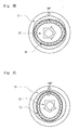
- Fig. 1 is a diagram showing a structure of the harmonic drive gear.
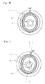
- Figs. 2A to 2D are diagrams describing an operation of the harmonic drive gear.
- a harmonic drive gear 10 is a mechanism that reduces the speed of the rotation of an input shaft with an extremely large reduction ratio (extremely large reduction ratio of several tens or several hundreds) to transmit it to an output shaft.
- the harmonic drive gear 10 includes a circular spline 11 as an external gear, a flex spline 12 as an intermediate gear, and a wave generator 13 as an internal gear.
- Inner teeth are formed in an inner side of a housing case provided to contain the harmonic drive gear 10, thereby forming the circular spline 11 as the external gear.
- a plurality of pressing balls are arranged at equal intervals along the outer periphery of an elliptic cam, thereby forming the wave generator (internal gear) 13.
- the flex spline (intermediate gear) 12 is formed of an elastic material, and the wave generator 13 is arranged in the inner side of the flex spline 12 along the inner peripheral surface.
- Outer teeth are formed in an outer periphery of the flex spline (intermediate gear) 12, and the outer teeth are formed to mesh with the circular spline 11 which is the external gear.
- the flex spline (internal gear) 12 is elastically deformed into an elliptical shape. Then two parts corresponding to the long shaft of the ellipse are pressed to the outermost peripheral side to mesh with the circular spline 12. Note that the number of teeth of the circular spline 11 is larger than the number of teeth of the flex spline 12 by two.
- the circular spline 11 which is the external gear is fixed
- the input shaft is coupled to the wave generator 13
- the output shaft is coupled to the flex spline 12.
- the elliptic cam of the wave generator 13 is also rotated and a mesh position between the flex spline 12 and the circular spline 11 is also rotated.
- Figs. 2A to 2D are diagrams showing a case in which the circular spline 11 is fixed and the wave generator 13 makes one turn.
- the number of teeth of the flex spline 12 is smaller than the number of teeth of the circular spline 11 by two.
- the flex spline 12 rotates in the opposite direction by the amount corresponding to the difference in the number of teeth, i.e., two teeth ( ⁇ deg). In this way, an extremely large reduction ratio is achieved by the harmonic drive gear 10.
- the wave generator 13 is rotated in a state in which the circular spline 11 is fixed.
- the circular spline 11 is also rotated while being coupled to drive means (motor) without fixing the circular spline 11.
- the circular spline 11 is rotated by ⁇ deg while the wave generator 13 is rotated by 360+ ⁇ deg in the same direction.
- the flex spline 12 does not rotate at all from the initial position.
- by rotating the internal gear (wave generator 13) and the external gear (circular spline 11) with some speed difference it is possible to create a state in which the intermediate gear (flex spline 12) does not rotate at all.
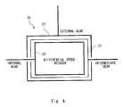
- the differential speed reducer is schematically expressed as shown in Fig. 4 .
- the differential speed reducer 20 is expressed by triple boxes: the outermost box is an external gear 21, the innermost box is an internal gear 23, and the box between the two boxes is an intermediate gear 22.
- the differential speed reducer is a harmonic drive gear
- the external gear 21 corresponds to the circular spline 11
- the intermediate gear 22 corresponds to the flex spline 12
- the internal gear 23 corresponds to the wave generator 13.
- a joint structure of a robot includes a motor and a differential speed reducer arranged between a first link and a second link, and relatively rotates the second link with respect to the first link by a drive force of the motor.
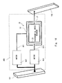
- Fig. 5 shows a related robot joint unit 100 as a comparative example.
- a motor 110 is fixed to a first link 101, and an output shaft 111 of the motor 110 is coupled to an internal gear (wave generator) 23. Further, an external gear (circular spline) 21 is fixed to the first link 101. An intermediate gear (flex spline) 22 is coupled to a second link 102.
- the motor 110 rotationally drives. Since the drive of the motor rotates the motor output shaft 111, the internal gear (wave generator) 22 rotates integrally with the output shaft 111. When the internal gear (wave generator) 22 rotates, the rotational speed of the intermediate gear (flex spline) 22 is reduced by the mesh of the external gear (circular spline) 21 with the intermediate gear (flex spline) 22. The rotation of the intermediate gear (flex spline) 22 is transmitted to the second link 102 as an output, thereby driving the second link 102.
- the joint unit 100 in order to keep the second link 102 stationary with respect to the first link 101, it is naturally required to stop the drive of the motor. Accordingly, when the second link 102 stops, large static friction acts among the three elements (internal gear 23, intermediate gear 22, and external gear 21) of the differential speed reducer. In this case, even when a force is applied from the side of the second link in the stationary state, the second link 102 cannot move due to large friction resistance in the differential speed reducer. For example, the joint unit 100 does not move even if a person touches the second link 102, and thus it is impossible to mitigate the power at the time of contact.
- two motors are used to continuously rotate two of the three elements of the differential speed reducer 20 with a predetermined speed difference.
- An exemplary embodiment according to the present invention may include the patterns described as follows.
- Fig. 6 shows a first pattern
- first motor 210 is fixed to a first link 101, and an output shaft 211 of the first motor 210 is coupled to an internal gear (wave generator) 23 of a differential speed reducer 20. While the second motor 220 is also fixed to the first link 101, an output shaft 221 of the second motor 220 is coupled to an external gear (circular spline) 21 of the differential speed reducer 20.
- a second link 102 is coupled to an intermediate gear (flex spline) 22 of the differential speed reducer 20.
- differential speed reducer 20 is a harmonic drive gear 10
- the number of teeth of the circular spline (external gear) 11 is denoted by Zc
- the number of teeth of the flex spline (intermediate gear) 12 is denoted by Zf.
- the rotational speed of the wave generator (internal gear) 13 is denoted by Vw
- the rotational speed of the flex spline (intermediate gear) 12 is denoted by Vf
- the rotational speed of the circular spline (external gear) 11 is denoted by Vc.
- speed difference here means a rotational speed difference between the wave generator (internal gear) 13 and the flex spline (intermediate gear) 12.
- a command current may be applied to each of the first motor 210 and the second motor 220 in order to achieve the rotational speed that is required.
- the rotation of the intermediate gear (flex spline) 22 is generated by a relative rotation between the internal gear (wave generator) 23 and the external gear (circular spline) 21, the internal gear (wave generator) 23 and the external gear (circular spline) 21 may be rotated in opposite directions.
- the rotative power of the intermediate gear (flex spline) 22 can be shared between the first motor 210 and the second motor 220, whereby the load of the first motor 210 can be mitigated.
- the force applied to the second link 102 may easily be transmitted to the input shaft from the output shaft of the differential speed reducer 20.
- Fig. 8 shows a second pattern.
- a first motor 310 is fixed to the first link 101, and an output shaft 311 of the first motor 310 is coupled to the internal gear (wave generator) 23 of the differential speed reducer 20.
- a second motor 320 is also fixed to the first link 101, an output shaft 321 of the second motor 320 is coupled to the intermediate gear (flex spline) 22 of the differential speed reducer 20.
- the second link is coupled to the external gear of the differential speed reducer.
- the rotational speed of each of the wave generator (internal gear) 13 and the rotational speed of the flex spline (intermediate gear) 12 are obtained based on the friction model in order to minimize the friction in the differential speed reducer in the state in which the joint is stopped.
- the external gear (circular spline) 21 rotates, whereby the second link 102 drives to perform the joint motion.
- the internal gear (wave generator) 23 and the intermediate gear (flex spline) 22 may be rotated in the same direction.
- the load of the first motor 310 can be mitigated since the rotative power of the external gear (circular spline) 21 can be shared between the first motor 310 and the second motor 320.
- differential speed reducer is the harmonic drive gear (harmonic drive (registered trademark))
- harmonic drive registered trademark
- a planetary gear drive 30 includes, as shown in Fig. 9 , an outer gear 31, a plurality of planetary gears 32, a planetary carrier 33 that receives revolution of the planetary gears 32, and a sun gear 34.
- the planetary gears 32 mesh with the sun gear 34 and the outer gear 31, and perform rotation and revolution.
- the outer gear 31 corresponds to the external gear 21
- the planetary gears 32 and the planetary carrier 33 correspond to the intermediate gear 22
- the sun gear 34 corresponds to the internal gear 23.
- the above first pattern and the second pattern may be applied also to the planetary gear drive 30.
- the above first pattern and the second pattern may be applied also to the planetary gear mechanism.
- the planetary gear drive 30 is applied to the second pattern.
- the first motor 310 is fixed to the first link 101, and at the same time the output shaft 311 of the first motor 310 is coupled to the internal gear (sun gear) 23 of the differential speed reducer 20.
- the second motor 320 is fixed to the first link 101, and the output shaft 321 of the second motor 320 is coupled to the intermediate gear (planetary gear, planetary carrier) 22 of the differential speed reducer 20.
- the second link 102 is coupled to the external gear (outer gear) 21 of the differential speed reducer 20.
- the number of teeth of the sun gear 34 is Zs
- the number of teeth of the planetary gear 32 is Zp
- the number of teeth of the outer gear 31 is Zo.
- the rotational speed of the sun gear 34 is denoted by Vs
- the rotational speed (revolution speed of the planetary gear) of the planetary carrier 33 is denoted by Vp
- the rotational speed of the outer gear 31 is denoted by Vo.
- Fig. 10 shows the third pattern.
- a first motor 410 is fixed to the first link 101, and an output shaft 411 of the first motor 410 is coupled to the intermediate gear (planetary gear, planetary carrier) 22 of the differential speed reducer 20.
- the second link 102 is coupled to the internal gear (sun gear) 23 of the differential speed reducer 20.
- differential speed reducer While the harmonic drive gear and the planetary gear drive have been exemplified as the differential speed reducer, other devices may be applied as the differential speed reducer.
- all of the first pattern, the second pattern, and the third pattern may be applied to the harmonic drive gear, and further all the first pattern, the second pattern, and the third pattern may be applied to the planetary gear drive.
Landscapes
- Engineering & Computer Science (AREA)
- Robotics (AREA)
- Mechanical Engineering (AREA)
- Manipulator (AREA)
- Retarders (AREA)
Applications Claiming Priority (1)
| Application Number | Priority Date | Filing Date | Title |
|---|---|---|---|
| PCT/JP2011/001704 WO2012127532A1 (fr) | 2011-03-23 | 2011-03-23 | Procédé d'entraînement pour dispositif d'articulation |
Publications (3)
| Publication Number | Publication Date |
|---|---|
| EP2689900A1 true EP2689900A1 (fr) | 2014-01-29 |
| EP2689900A4 EP2689900A4 (fr) | 2014-05-07 |
| EP2689900B1 EP2689900B1 (fr) | 2015-07-08 |
Family
ID=46878736
Family Applications (1)
| Application Number | Title | Priority Date | Filing Date |
|---|---|---|---|
| EP11852221.8A Not-in-force EP2689900B1 (fr) | 2011-03-23 | 2011-03-23 | Procédé d'entraînement pour dispositif d'articulation |
Country Status (5)
| Country | Link |
|---|---|
| US (1) | US8733207B2 (fr) |
| EP (1) | EP2689900B1 (fr) |
| JP (1) | JP5387775B2 (fr) |
| CN (1) | CN103153556B (fr) |
| WO (1) | WO2012127532A1 (fr) |
Families Citing this family (9)
| Publication number | Priority date | Publication date | Assignee | Title |
|---|---|---|---|---|
| JP5997581B2 (ja) * | 2012-10-24 | 2016-09-28 | セイコーエプソン株式会社 | 電気機械装置、並びに、これを備える移動体およびロボット |
| JP6228837B2 (ja) * | 2013-12-25 | 2017-11-08 | 富士通周辺機株式会社 | マニピュレータ駆動制御装置 |
| US9371899B2 (en) * | 2014-05-27 | 2016-06-21 | Hamilton Sundstrand Corporation | Harmonic drive assembly with selective disconnect and reconnect |
| DE102015200374A1 (de) * | 2015-01-13 | 2016-07-14 | Kuka Roboter Gmbh | Getriebe, elektrische Antriebsvorrichtung und Industrieroboter |
| CN104712711B (zh) * | 2015-02-09 | 2018-05-11 | 陈志同 | 一种可用于机器人关节减速器的余弦渐开线少齿差传动装置 |
| WO2018229987A1 (fr) * | 2017-06-16 | 2018-12-20 | 株式会社ハーモニック・ドライブ・システムズ | Dispositif d'engrenage à ondes |
| CN108032328B (zh) * | 2017-12-18 | 2023-08-04 | 深圳市优必选科技有限公司 | 一种舵机组件、机器人关节结构及机器人 |
| CN110788847B (zh) * | 2019-11-22 | 2021-01-15 | 合肥工业大学 | 一种有辅助驱动单元的节能型工业机器人 |
| JPWO2023090204A1 (fr) * | 2021-11-16 | 2023-05-25 |
Family Cites Families (33)
| Publication number | Priority date | Publication date | Assignee | Title |
|---|---|---|---|---|
| JPS61147407U (fr) | 1985-02-27 | 1986-09-11 | ||
| JP2606236B2 (ja) | 1987-10-13 | 1997-04-30 | 株式会社安川電機 | 非線形摩擦補償を行った高速位置決め制御方法 |
| JP2681969B2 (ja) | 1988-02-17 | 1997-11-26 | 株式会社安川電機 | 可変構造系によるクーロン摩擦の補償方法 |
| JPH0248710A (ja) | 1988-08-11 | 1990-02-19 | Fanuc Ltd | ソフトウェアサーボにおける静摩擦補償方法 |
| JPH04257001A (ja) | 1991-02-08 | 1992-09-11 | Fanuc Ltd | ゲインスケジューリング |
| US5222409A (en) * | 1991-09-25 | 1993-06-29 | Dalakian Sergei V | Industrial robot arms |
| DE69315318D1 (de) | 1992-12-07 | 1998-01-02 | Koninkl Philips Electronics Nv | Steuerungseinrichtung |
| JPH06309008A (ja) | 1993-04-20 | 1994-11-04 | Mitsubishi Heavy Ind Ltd | サーボ制御装置 |
| JP3463355B2 (ja) | 1994-06-03 | 2003-11-05 | 株式会社安川電機 | 制御対象の特性を表す関数の定数の同定・補償方法 |
| JP2619227B2 (ja) | 1994-11-30 | 1997-06-11 | 川崎重工業株式会社 | ロボットの制御方法および装置 |
| JPH08286759A (ja) | 1995-04-14 | 1996-11-01 | Fanuc Ltd | 静摩擦を補償するロボット駆動制御方法 |
| JPH08308178A (ja) * | 1995-05-08 | 1996-11-22 | Shigeto Suzuki | モーター装置 |
| JPH09231701A (ja) | 1996-02-21 | 1997-09-05 | Hitachi Ltd | ヘッド位置決め制御方法 |
| JP3552076B2 (ja) | 1996-06-20 | 2004-08-11 | 株式会社安川電機 | ロボット制御方法 |
| JP3416474B2 (ja) | 1997-08-07 | 2003-06-16 | 三菱電機株式会社 | 電動式パワーステアリング装置 |
| JPH11123690A (ja) | 1997-10-24 | 1999-05-11 | Denso Corp | 多関節形ロボット |
| JP4038805B2 (ja) | 1997-11-11 | 2008-01-30 | 株式会社安川電機 | 電動機の摩擦補償方法 |
| CN2389046Y (zh) * | 1999-09-30 | 2000-07-26 | 上海交通大学 | Sma丝差动驱动的转动关节臂 |
| JP2002046632A (ja) | 2000-08-07 | 2002-02-12 | Nsk Ltd | 電動パワーステアリング装置の制御装置 |
| JP3949470B2 (ja) | 2002-02-27 | 2007-07-25 | 本田技研工業株式会社 | プラントの制御装置 |
| JP2004195576A (ja) | 2002-12-17 | 2004-07-15 | Japan Science & Technology Agency | 機能性流体を用いた柔軟関節マニピュレータ |
| JP4614427B2 (ja) | 2003-08-06 | 2011-01-19 | 日産自動車株式会社 | 低摩擦摺動機構、手動変速機及び終減速機 |
| JP2005186258A (ja) * | 2003-12-26 | 2005-07-14 | Daihen Corp | 作業用ロボット |
| JP4148189B2 (ja) | 2004-06-14 | 2008-09-10 | トヨタ自動車株式会社 | 柔軟関節ロボットアームの制御装置 |
| JP4453526B2 (ja) | 2004-11-19 | 2010-04-21 | 株式会社安川電機 | サーボ制御装置 |
| JP2007001444A (ja) | 2005-06-24 | 2007-01-11 | Toyota Motor Corp | 車両用駆動装置 |
| JP2007085530A (ja) * | 2005-09-26 | 2007-04-05 | Nabtesco Corp | 中空減速機 |
| WO2007072546A1 (fr) * | 2005-12-20 | 2007-06-28 | Harmonic Drive Systems Inc. | Mecanisme d'articulation de doigt |
| US7891272B2 (en) * | 2006-11-14 | 2011-02-22 | Schonlau William J | Robotic harmonic flex-drive |
| JP5135031B2 (ja) * | 2007-10-05 | 2013-01-30 | 株式会社リコー | 連結装置および画像形成装置 |
| JP2009166219A (ja) * | 2008-01-21 | 2009-07-30 | Toyota Motor Corp | ロボットアームの関節機構 |
| JP2009291874A (ja) * | 2008-06-04 | 2009-12-17 | Kansai Electric Power Co Inc:The | 関節装置、ロボットアーム、及び、フィンガーユニット |
| JP2010266008A (ja) * | 2009-05-15 | 2010-11-25 | Denso Wave Inc | ロボット用ハーモニック減速機 |
-
2011
- 2011-03-23 US US13/577,416 patent/US8733207B2/en active Active
- 2011-03-23 JP JP2012525781A patent/JP5387775B2/ja not_active Expired - Fee Related
- 2011-03-23 CN CN201180016120.5A patent/CN103153556B/zh not_active Expired - Fee Related
- 2011-03-23 WO PCT/JP2011/001704 patent/WO2012127532A1/fr not_active Ceased
- 2011-03-23 EP EP11852221.8A patent/EP2689900B1/fr not_active Not-in-force
Non-Patent Citations (2)
| Title |
|---|
| No further relevant documents disclosed * |
| See also references of WO2012127532A1 * |
Also Published As
| Publication number | Publication date |
|---|---|
| CN103153556A (zh) | 2013-06-12 |
| JP5387775B2 (ja) | 2014-01-15 |
| EP2689900B1 (fr) | 2015-07-08 |
| JPWO2012127532A1 (ja) | 2014-07-24 |
| CN103153556B (zh) | 2014-08-20 |
| US20130074636A1 (en) | 2013-03-28 |
| EP2689900A4 (fr) | 2014-05-07 |
| WO2012127532A1 (fr) | 2012-09-27 |
| US8733207B2 (en) | 2014-05-27 |
Similar Documents
| Publication | Publication Date | Title |
|---|---|---|
| EP2689900B1 (fr) | Procédé d'entraînement pour dispositif d'articulation | |
| US20150239133A1 (en) | Gravity-counterbalanced robot arm | |
| US9273758B2 (en) | Power transmission device | |
| US20130042715A1 (en) | Low-stroke actuation for a serial robot | |
| US9664275B2 (en) | Zero backlash right angle transmission system and method | |
| CN104690722B (zh) | 一种五自由度机器人 | |
| Pisetskiy et al. | Design and development of the transmission for a fully actuated 5-degrees-of-freedom compliant robot manipulator with a single motor | |
| CN203712693U (zh) | 一种三平移并联机构及其支链 | |
| EP3822511B1 (fr) | Transmission planetaire a haut rapport | |
| KR102782209B1 (ko) | 웨어러블 로봇용 케이블 구동 회전 관절 장치 | |
| CN203831415U (zh) | 一种机器人腕部驱动机构 | |
| CN103899720B (zh) | 用于精密动力传递系统的可逆向驱动减速机构 | |
| Terfurth et al. | Integrated planetary gear joint actuator concept for wearable and industrial robotic applications | |
| Mehmood et al. | Rotational twisted string actuator with linearized output: Mathematical model and experimental evaluation | |
| KR101201415B1 (ko) | 가동풀리를 이용한 액추에이터 | |
| JP2020185655A (ja) | リンク機構 | |
| KR100963633B1 (ko) | 로봇용 어깨 관절 액츄에이터 | |
| KR101749572B1 (ko) | 로봇 관절 구동장치 및 이를 포함하는 로봇 | |
| JPH0328612B2 (fr) | ||
| JP2006297553A (ja) | 可動軸駆動装置 | |
| CN202963823U (zh) | 一种新型焊割机器人结构 | |
| JP2007298114A (ja) | 駆動装置及び関節装置 | |
| RU2524498C1 (ru) | Шаговый привод с механическим побуждением и нулевым обратным усилием | |
| JP2017177233A (ja) | 関節駆動装置及び多軸マニュピレータ | |
| JP2016525657A (ja) | 湾曲軸受接触システム |
Legal Events
| Date | Code | Title | Description |
|---|---|---|---|
| PUAI | Public reference made under article 153(3) epc to a published international application that has entered the european phase |
Free format text: ORIGINAL CODE: 0009012 |
|
| 17P | Request for examination filed |
Effective date: 20120706 |
|
| AK | Designated contracting states |
Kind code of ref document: A1 Designated state(s): AL AT BE BG CH CY CZ DE DK EE ES FI FR GB GR HR HU IE IS IT LI LT LU LV MC MK MT NL NO PL PT RO RS SE SI SK SM TR |
|
| A4 | Supplementary search report drawn up and despatched |
Effective date: 20140408 |
|
| RIC1 | Information provided on ipc code assigned before grant |
Ipc: B25J 17/00 20060101AFI20140402BHEP |
|
| DAX | Request for extension of the european patent (deleted) | ||
| GRAP | Despatch of communication of intention to grant a patent |
Free format text: ORIGINAL CODE: EPIDOSNIGR1 |
|
| INTG | Intention to grant announced |
Effective date: 20150128 |
|
| GRAS | Grant fee paid |
Free format text: ORIGINAL CODE: EPIDOSNIGR3 |
|
| GRAA | (expected) grant |
Free format text: ORIGINAL CODE: 0009210 |
|
| AK | Designated contracting states |
Kind code of ref document: B1 Designated state(s): AL AT BE BG CH CY CZ DE DK EE ES FI FR GB GR HR HU IE IS IT LI LT LU LV MC MK MT NL NO PL PT RO RS SE SI SK SM TR |
|
| REG | Reference to a national code |
Ref country code: GB Ref legal event code: FG4D |
|
| REG | Reference to a national code |
Ref country code: AT Ref legal event code: REF Ref document number: 735022 Country of ref document: AT Kind code of ref document: T Effective date: 20150715 Ref country code: CH Ref legal event code: EP |
|
| REG | Reference to a national code |
Ref country code: IE Ref legal event code: FG4D |
|
| REG | Reference to a national code |
Ref country code: DE Ref legal event code: R096 Ref document number: 602011017803 Country of ref document: DE |
|
| REG | Reference to a national code |
Ref country code: AT Ref legal event code: MK05 Ref document number: 735022 Country of ref document: AT Kind code of ref document: T Effective date: 20150708 |
|
| REG | Reference to a national code |
Ref country code: NL Ref legal event code: MP Effective date: 20150708 |
|
| REG | Reference to a national code |
Ref country code: LT Ref legal event code: MG4D Ref country code: DE Ref legal event code: R084 Ref document number: 602011017803 Country of ref document: DE |
|
| REG | Reference to a national code |
Ref country code: GB Ref legal event code: 746 Effective date: 20160105 |
|
| PG25 | Lapsed in a contracting state [announced via postgrant information from national office to epo] |
Ref country code: LV Free format text: LAPSE BECAUSE OF FAILURE TO SUBMIT A TRANSLATION OF THE DESCRIPTION OR TO PAY THE FEE WITHIN THE PRESCRIBED TIME-LIMIT Effective date: 20150708 Ref country code: FI Free format text: LAPSE BECAUSE OF FAILURE TO SUBMIT A TRANSLATION OF THE DESCRIPTION OR TO PAY THE FEE WITHIN THE PRESCRIBED TIME-LIMIT Effective date: 20150708 Ref country code: GR Free format text: LAPSE BECAUSE OF FAILURE TO SUBMIT A TRANSLATION OF THE DESCRIPTION OR TO PAY THE FEE WITHIN THE PRESCRIBED TIME-LIMIT Effective date: 20151009 Ref country code: NO Free format text: LAPSE BECAUSE OF FAILURE TO SUBMIT A TRANSLATION OF THE DESCRIPTION OR TO PAY THE FEE WITHIN THE PRESCRIBED TIME-LIMIT Effective date: 20151008 Ref country code: LT Free format text: LAPSE BECAUSE OF FAILURE TO SUBMIT A TRANSLATION OF THE DESCRIPTION OR TO PAY THE FEE WITHIN THE PRESCRIBED TIME-LIMIT Effective date: 20150708 |
|
| REG | Reference to a national code |
Ref country code: FR Ref legal event code: PLFP Year of fee payment: 6 |
|
| PG25 | Lapsed in a contracting state [announced via postgrant information from national office to epo] |
Ref country code: RS Free format text: LAPSE BECAUSE OF FAILURE TO SUBMIT A TRANSLATION OF THE DESCRIPTION OR TO PAY THE FEE WITHIN THE PRESCRIBED TIME-LIMIT Effective date: 20150708 Ref country code: HR Free format text: LAPSE BECAUSE OF FAILURE TO SUBMIT A TRANSLATION OF THE DESCRIPTION OR TO PAY THE FEE WITHIN THE PRESCRIBED TIME-LIMIT Effective date: 20150708 Ref country code: PT Free format text: LAPSE BECAUSE OF FAILURE TO SUBMIT A TRANSLATION OF THE DESCRIPTION OR TO PAY THE FEE WITHIN THE PRESCRIBED TIME-LIMIT Effective date: 20151109 Ref country code: AT Free format text: LAPSE BECAUSE OF FAILURE TO SUBMIT A TRANSLATION OF THE DESCRIPTION OR TO PAY THE FEE WITHIN THE PRESCRIBED TIME-LIMIT Effective date: 20150708 Ref country code: PL Free format text: LAPSE BECAUSE OF FAILURE TO SUBMIT A TRANSLATION OF THE DESCRIPTION OR TO PAY THE FEE WITHIN THE PRESCRIBED TIME-LIMIT Effective date: 20150708 Ref country code: IS Free format text: LAPSE BECAUSE OF FAILURE TO SUBMIT A TRANSLATION OF THE DESCRIPTION OR TO PAY THE FEE WITHIN THE PRESCRIBED TIME-LIMIT Effective date: 20151108 Ref country code: ES Free format text: LAPSE BECAUSE OF FAILURE TO SUBMIT A TRANSLATION OF THE DESCRIPTION OR TO PAY THE FEE WITHIN THE PRESCRIBED TIME-LIMIT Effective date: 20150708 Ref country code: SE Free format text: LAPSE BECAUSE OF FAILURE TO SUBMIT A TRANSLATION OF THE DESCRIPTION OR TO PAY THE FEE WITHIN THE PRESCRIBED TIME-LIMIT Effective date: 20150708 |
|
| REG | Reference to a national code |
Ref country code: DE Ref legal event code: R097 Ref document number: 602011017803 Country of ref document: DE |
|
| PG25 | Lapsed in a contracting state [announced via postgrant information from national office to epo] |
Ref country code: CZ Free format text: LAPSE BECAUSE OF FAILURE TO SUBMIT A TRANSLATION OF THE DESCRIPTION OR TO PAY THE FEE WITHIN THE PRESCRIBED TIME-LIMIT Effective date: 20150708 Ref country code: IT Free format text: LAPSE BECAUSE OF FAILURE TO SUBMIT A TRANSLATION OF THE DESCRIPTION OR TO PAY THE FEE WITHIN THE PRESCRIBED TIME-LIMIT Effective date: 20150708 Ref country code: EE Free format text: LAPSE BECAUSE OF FAILURE TO SUBMIT A TRANSLATION OF THE DESCRIPTION OR TO PAY THE FEE WITHIN THE PRESCRIBED TIME-LIMIT Effective date: 20150708 Ref country code: DK Free format text: LAPSE BECAUSE OF FAILURE TO SUBMIT A TRANSLATION OF THE DESCRIPTION OR TO PAY THE FEE WITHIN THE PRESCRIBED TIME-LIMIT Effective date: 20150708 Ref country code: SK Free format text: LAPSE BECAUSE OF FAILURE TO SUBMIT A TRANSLATION OF THE DESCRIPTION OR TO PAY THE FEE WITHIN THE PRESCRIBED TIME-LIMIT Effective date: 20150708 |
|
| PLBE | No opposition filed within time limit |
Free format text: ORIGINAL CODE: 0009261 |
|
| STAA | Information on the status of an ep patent application or granted ep patent |
Free format text: STATUS: NO OPPOSITION FILED WITHIN TIME LIMIT |
|
| PG25 | Lapsed in a contracting state [announced via postgrant information from national office to epo] |
Ref country code: RO Free format text: LAPSE BECAUSE OF FAILURE TO SUBMIT A TRANSLATION OF THE DESCRIPTION OR TO PAY THE FEE WITHIN THE PRESCRIBED TIME-LIMIT Effective date: 20150708 |
|
| 26N | No opposition filed |
Effective date: 20160411 |
|
| PG25 | Lapsed in a contracting state [announced via postgrant information from national office to epo] |
Ref country code: BE Free format text: LAPSE BECAUSE OF NON-PAYMENT OF DUE FEES Effective date: 20160331 Ref country code: SI Free format text: LAPSE BECAUSE OF FAILURE TO SUBMIT A TRANSLATION OF THE DESCRIPTION OR TO PAY THE FEE WITHIN THE PRESCRIBED TIME-LIMIT Effective date: 20150708 |
|
| PG25 | Lapsed in a contracting state [announced via postgrant information from national office to epo] |
Ref country code: MC Free format text: LAPSE BECAUSE OF FAILURE TO SUBMIT A TRANSLATION OF THE DESCRIPTION OR TO PAY THE FEE WITHIN THE PRESCRIBED TIME-LIMIT Effective date: 20150708 Ref country code: LU Free format text: LAPSE BECAUSE OF FAILURE TO SUBMIT A TRANSLATION OF THE DESCRIPTION OR TO PAY THE FEE WITHIN THE PRESCRIBED TIME-LIMIT Effective date: 20160323 |
|
| REG | Reference to a national code |
Ref country code: CH Ref legal event code: PL |
|
| REG | Reference to a national code |
Ref country code: IE Ref legal event code: MM4A |
|
| PG25 | Lapsed in a contracting state [announced via postgrant information from national office to epo] |
Ref country code: BE Free format text: LAPSE BECAUSE OF FAILURE TO SUBMIT A TRANSLATION OF THE DESCRIPTION OR TO PAY THE FEE WITHIN THE PRESCRIBED TIME-LIMIT Effective date: 20150708 |
|
| PG25 | Lapsed in a contracting state [announced via postgrant information from national office to epo] |
Ref country code: LI Free format text: LAPSE BECAUSE OF NON-PAYMENT OF DUE FEES Effective date: 20160331 Ref country code: CH Free format text: LAPSE BECAUSE OF NON-PAYMENT OF DUE FEES Effective date: 20160331 Ref country code: IE Free format text: LAPSE BECAUSE OF NON-PAYMENT OF DUE FEES Effective date: 20160323 |
|
| REG | Reference to a national code |
Ref country code: FR Ref legal event code: PLFP Year of fee payment: 7 |
|
| PG25 | Lapsed in a contracting state [announced via postgrant information from national office to epo] |
Ref country code: NL Free format text: LAPSE BECAUSE OF FAILURE TO SUBMIT A TRANSLATION OF THE DESCRIPTION OR TO PAY THE FEE WITHIN THE PRESCRIBED TIME-LIMIT Effective date: 20150708 |
|
| PG25 | Lapsed in a contracting state [announced via postgrant information from national office to epo] |
Ref country code: MT Free format text: LAPSE BECAUSE OF FAILURE TO SUBMIT A TRANSLATION OF THE DESCRIPTION OR TO PAY THE FEE WITHIN THE PRESCRIBED TIME-LIMIT Effective date: 20150708 |
|
| REG | Reference to a national code |
Ref country code: FR Ref legal event code: PLFP Year of fee payment: 8 |
|
| PG25 | Lapsed in a contracting state [announced via postgrant information from national office to epo] |
Ref country code: HU Free format text: LAPSE BECAUSE OF FAILURE TO SUBMIT A TRANSLATION OF THE DESCRIPTION OR TO PAY THE FEE WITHIN THE PRESCRIBED TIME-LIMIT; INVALID AB INITIO Effective date: 20110323 Ref country code: SM Free format text: LAPSE BECAUSE OF FAILURE TO SUBMIT A TRANSLATION OF THE DESCRIPTION OR TO PAY THE FEE WITHIN THE PRESCRIBED TIME-LIMIT Effective date: 20150708 Ref country code: CY Free format text: LAPSE BECAUSE OF FAILURE TO SUBMIT A TRANSLATION OF THE DESCRIPTION OR TO PAY THE FEE WITHIN THE PRESCRIBED TIME-LIMIT Effective date: 20150708 |
|
| PG25 | Lapsed in a contracting state [announced via postgrant information from national office to epo] |
Ref country code: TR Free format text: LAPSE BECAUSE OF FAILURE TO SUBMIT A TRANSLATION OF THE DESCRIPTION OR TO PAY THE FEE WITHIN THE PRESCRIBED TIME-LIMIT Effective date: 20150708 Ref country code: MK Free format text: LAPSE BECAUSE OF FAILURE TO SUBMIT A TRANSLATION OF THE DESCRIPTION OR TO PAY THE FEE WITHIN THE PRESCRIBED TIME-LIMIT Effective date: 20150708 Ref country code: MT Free format text: LAPSE BECAUSE OF FAILURE TO SUBMIT A TRANSLATION OF THE DESCRIPTION OR TO PAY THE FEE WITHIN THE PRESCRIBED TIME-LIMIT Effective date: 20160331 |
|
| PG25 | Lapsed in a contracting state [announced via postgrant information from national office to epo] |
Ref country code: BG Free format text: LAPSE BECAUSE OF FAILURE TO SUBMIT A TRANSLATION OF THE DESCRIPTION OR TO PAY THE FEE WITHIN THE PRESCRIBED TIME-LIMIT Effective date: 20150708 |
|
| PG25 | Lapsed in a contracting state [announced via postgrant information from national office to epo] |
Ref country code: AL Free format text: LAPSE BECAUSE OF FAILURE TO SUBMIT A TRANSLATION OF THE DESCRIPTION OR TO PAY THE FEE WITHIN THE PRESCRIBED TIME-LIMIT Effective date: 20150708 |
|
| PGFP | Annual fee paid to national office [announced via postgrant information from national office to epo] |
Ref country code: GB Payment date: 20220127 Year of fee payment: 12 Ref country code: DE Payment date: 20220203 Year of fee payment: 12 |
|
| PGFP | Annual fee paid to national office [announced via postgrant information from national office to epo] |
Ref country code: FR Payment date: 20220209 Year of fee payment: 12 |
|
| P01 | Opt-out of the competence of the unified patent court (upc) registered |
Effective date: 20230427 |
|
| REG | Reference to a national code |
Ref country code: DE Ref legal event code: R119 Ref document number: 602011017803 Country of ref document: DE |
|
| GBPC | Gb: european patent ceased through non-payment of renewal fee |
Effective date: 20230323 |
|
| PG25 | Lapsed in a contracting state [announced via postgrant information from national office to epo] |
Ref country code: GB Free format text: LAPSE BECAUSE OF NON-PAYMENT OF DUE FEES Effective date: 20230323 |
|
| PG25 | Lapsed in a contracting state [announced via postgrant information from national office to epo] |
Ref country code: GB Free format text: LAPSE BECAUSE OF NON-PAYMENT OF DUE FEES Effective date: 20230323 Ref country code: FR Free format text: LAPSE BECAUSE OF NON-PAYMENT OF DUE FEES Effective date: 20230331 Ref country code: DE Free format text: LAPSE BECAUSE OF NON-PAYMENT OF DUE FEES Effective date: 20231003 |