EP2689904A1 - Procédé d'installation mécanique séquentielle d'attaches séparées dans les encoches de panneaux de construction en forme de plaques ainsi que le dispositif d'exécution du procédé - Google Patents
Procédé d'installation mécanique séquentielle d'attaches séparées dans les encoches de panneaux de construction en forme de plaques ainsi que le dispositif d'exécution du procédé Download PDFInfo
- Publication number
- EP2689904A1 EP2689904A1 EP12005481.2A EP12005481A EP2689904A1 EP 2689904 A1 EP2689904 A1 EP 2689904A1 EP 12005481 A EP12005481 A EP 12005481A EP 2689904 A1 EP2689904 A1 EP 2689904A1
- Authority
- EP
- European Patent Office
- Prior art keywords
- rotary conveyor
- connector
- application head
- connectors
- building panel
- Prior art date
- Legal status (The legal status is an assumption and is not a legal conclusion. Google has not performed a legal analysis and makes no representation as to the accuracy of the status listed.)
- Granted
Links
Images





Classifications
-
- B—PERFORMING OPERATIONS; TRANSPORTING
- B27—WORKING OR PRESERVING WOOD OR SIMILAR MATERIAL; NAILING OR STAPLING MACHINES IN GENERAL
- B27M—WORKING OF WOOD NOT PROVIDED FOR IN SUBCLASSES B27B - B27L; MANUFACTURE OF SPECIFIC WOODEN ARTICLES
- B27M3/00—Manufacture or reconditioning of specific semi-finished or finished articles
- B27M3/04—Manufacture or reconditioning of specific semi-finished or finished articles of flooring elements, e.g. parqueting blocks
-
- E—FIXED CONSTRUCTIONS
- E04—BUILDING
- E04F—FINISHING WORK ON BUILDINGS, e.g. STAIRS, FLOORS
- E04F15/00—Flooring
- E04F15/02—Flooring or floor layers composed of a number of similar elements
-
- E—FIXED CONSTRUCTIONS
- E04—BUILDING
- E04F—FINISHING WORK ON BUILDINGS, e.g. STAIRS, FLOORS
- E04F2201/00—Joining sheets or plates or panels
- E04F2201/05—Separate connectors or inserts, e.g. pegs, pins, keys or strips
- E04F2201/0523—Separate tongues; Interlocking keys, e.g. joining mouldings of circular, square or rectangular shape
Definitions
- the invention relates to a method for automated, sequential insertion of separate connectors into slots of panel-shaped building panels, wherein preferably an endless profile with the cross-section of the connector is continuously fed to a cutting module and cut into sections corresponding to a predetermined length of the connector, and wherein the connectors are inserted by means of an insertion into the grooves of the building panel. Furthermore, the invention relates to a device for carrying out the method. Instead of the continuous feed, the connectors can also be removed from a magazine.
- Out DE 10 2004 062 648 B4 is a method for inserting connectors, called springs, known in grooves of technical wood products, in which the springs are prefabricated, sorted and aligned one above the other in a shaft magazine so that they are arranged in the longitudinal direction already parallel to the transport direction of the wood products.
- the springs are fed to a press-fit, which uses the springs by means of a pressure roller, an inclined plane or a lifting system in the grooves.
- the springs can be fed directly to a transfer device and cut there to the desired length become.
- the position of the connector inserted in the groove can be checked with the aid of a pressure roller connected downstream of the application head and corrected as required.
- the pressure roller does not function as a press-fit device and only performs the checking and correction function. It is possible to test, for example, with the aid of at least one optical sensor installed in the module of the pressure roller.
- rotary conveyor after each rotation about the angle ( ⁇ ) a rotating return movement by an angle of 0.5 ° to 2 °, preferably by an angle of 1 ° , can exercise. This allows a collision-free motion sequence of the application process.
- Another feature of the invention provides for a return movement of the application head after insertion of the separate connector into the groove.
- the profile feed, the cutting and the rotation can be carried out in a cyclic and time-saving manner independently of the application cycle.
- a great advantage of the method according to the invention is the possibility of the pulse-like pressing of the separate connector in the grooves of the passing building panels, with which the position of the connector on the respective building panel can be set with greater accuracy and repeatable.
- the position deviations can be, for example, ⁇ 5.0 mm with a panel length of 2.5 m.
- the device is integrated into a building panel processing station.
- the device then represents the last link of the Baupaneel processing station - seen in the direction of the building panel - dar they may also be located outside the building panel processing station.
- the attachment of the device to the building panel processing station is particularly well suited a perpendicular to the feed direction of the building panel housing wall of a building panel processing station, wherein the device is disposed within this equipped with exhaust ventilation housing. It is advantageous to move the device to a slide mounted on the housing, so that the position of the device can be regulated.
- the slider may be resiliently mounted on a free end of the movable application head.
- a resilient mounting refers in the present case to at least one accommodated in a seat of the slider and there fastened spring element, such as shock spring.
- the slider itself can be finger, web or plate-shaped.
- the application head can also be a contraction drive performing a stroke movement, so-called muscle drive (fluidic muscle).
- muscle drive (fluidic muscle).
- contraction drives are supplied, for example, by FESTO AG & Co. KG, Germany.
- the rotary conveyor may be provided with at least one pair of grippers for receiving and positioning the connector, which are preferably arranged mirror-symmetrically to one another at a periphery of the rotary conveyor, each gripper lying on the circumference of a side window of the rotary conveyor.
- the side windows are preferably circular.
- the gripper has a simple and proven construction, preferably a lever arm, which presses the connector by means of a spring element against a gripper base element.
- the parts of the device according to the invention namely the return and feed module, the profile feed device, the cutting module, the straightening device, the rotary conveyor and the application head and the pressure roller can be assembled into a compact unit manufactured in an open box design.
- the supporting parts of the unit may be formed by at least two base plates.
- the unit along at least two attached to the base plate and mutually parallel rails back and forth perpendicular to the feed direction of the building panel is arranged to be movable.
- the pressure roller remains stationary, d. H. their position opposite the passing building panels is constant.
- the pressure roller can be equipped with at least one optical sensor.
- the unit can be driven by the return and feed module.
- the base plate is fixed to a carriage attached to the housing wall of the building panel processing station.
- a processing station 200 for building panels 20 accommodated in a rectangular housing 14 comprising only partially shown parts of the processing station 200 and a device 100 located in the housing 14 according to the invention.
- the parts of the building panel processing station 200 are not relevant to the description of the present invention.
- the device 100 is arranged movably on a lateral housing wall 9 via a carriage 7, so that in a plane E which is defined by the housing wall 9 along the coordinates X, Z can be moved, adjusted and fixed there.
- an advancing direction R of the building panel 20 is shown with an arrow.
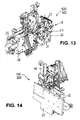
- the parts listed above are on two base plates 25, 26 arranged parallel to one another, a projecting support plate 30 running perpendicular to the base plate 26 and a bracket 31 (cf. Fig. 2 ) mounted in such a space-saving manner that a compact unit 300 is formed, which with its base plate 25 on a carriage 7 (see. Fig. 1 ) can be used.
- the compact design of the unit 300 is particularly good in FIGS. 13 and 14 to the fore. Despite its compact dimensions, the unit 300 fulfills all the required functions for the final assembly of panels.
- the profile feed device 3 is mounted on a mounting plate 32 with the cutting module 5 and the straightening device 6 forming a unit. This is shown in particular by the FIGS. 15 to 18 ,
- the profile feeder 3 itself consists essentially of a lower belt drive 33 and an upper, In between, the cut-to-length connectors 22 - in the operating state of the device 100 - are further transported by the frictional force.
- the pressure roller pair 34 presses against the passing connector 22 and at the same time against two lower driven rollers 35.1,35.2 of the belt drive 33, the drive roller 38 of a in Fig. 16 indicated servomotor 39 can be set in motion.
- the pivotable pressure roller pair 34 is of another in Fig. 16 shown servomotor 40 is actuated.
- the mentioned straightening device 6 is arranged on the mounting plate 32, comprising guide elements 36, 37 (cf. FIGS. 17 and 18 ) for the cut connectors 22.
- the cutting module 5 has a triangular blade 45 (see FIG. FIGS. 10, 11 and 15 ), with which the endless profile 18 can be intermittently cut, and a servo motor 41.
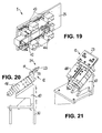
- the return and feed module 1 is in Fig. 19 to see.
- On the inside of the base plate 25 two superimposed guide rails 27.1, 27.2 and an intermediate servomotor 42 are fixed, wherein on the guide rails 27.1, 27.2 two guide carriage 43, such as trolley, are arranged, the Distanzklotzen 44 wear.
- the distance between the Distanzklotzen 44 and guide carriage 43 and the stroke of the cylinder of the servomotor are adjustable.
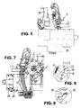
- the rotary conveyor 8 Details of the rotary conveyor 8 are the Figures 2 . 4 . 5 . 7 . 12 . 13 refer to. It consists of two rotatable about an axis of rotation A, rotationally symmetrical side windows 10.1, 10.2, which are provided at its periphery 4 each with a plurality of grippers 2.1, 2.2 for receiving and positioning the connector 22 (see. Fig. 12 ). In this case, the grippers of each gripper pair 2.1, 2.2, which receives the connector, arranged mirror-symmetrically to each other.
- the rotary conveyor 8 is set by means of a servo motor 46 cyclically in rotation. From the FIGS. 7 to 9 it is apparent that the gripper 2.1, 2.2 has a lever arm 15 which presses the connector 22 by means of a spring element 17 against a gripper base element 16.
- FIGS. 20 and 21 show the application head 12 with holder 47, part of which is the aforementioned support plate 30.
- the application head 12 is L-shaped in side view, wherein the slider 23 is arranged at its free, in the operating state in the direction of Bodenpaneel pointing end 24.
- the plate-shaped slide 23 is seated in a slot 29 of the application head 12 and is supported on a spring element 11.
- the application head 12 is set intermittently in translational movement by means of a servomotor 48.
- stationary pressure roller 13 is mounted on a support plate 48 via a servo motor 49 and a clamping module 50 with spring 51.
- the pressure roller 13 presses with its periphery against the pressed-in in the groove 21 connector 22nd
- the pressure roller 13 is provided with an optical sensor 28 which scans the groove or the connector.
- a pressure sensor can be used.
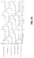
- the rotary conveyor 8 rotates backward by an angle of 1 °; then the connector 22 is pressed with the application head 12 abruptly into the groove 21. Thereafter, the return and feed module 1 moves into the position in which the rotary conveyor 8 is ready to rotate about the angle 37 °.
- the cycle of the rotational movement of the rotary conveyor 8 and the linear movement of the application head 12 is closed.
- the moving building panel 20 with the connector housed therein pulls over the pressure roller 13, so that the position of the connector can be corrected continuously.
Landscapes
- Engineering & Computer Science (AREA)
- Life Sciences & Earth Sciences (AREA)
- Manufacturing & Machinery (AREA)
- Wood Science & Technology (AREA)
- Forests & Forestry (AREA)
- Automatic Assembly (AREA)
Priority Applications (3)
| Application Number | Priority Date | Filing Date | Title |
|---|---|---|---|
| PL12005481T PL2689904T3 (pl) | 2012-07-27 | 2012-07-27 | Sposób maszynowego, sekwencyjnego wkładania oddzielnych łączników we wpusty płytowych paneli konstrukcyjnych i urządzenie do przeprowadzania sposobu |
| EP12005481.2A EP2689904B1 (fr) | 2012-07-27 | 2012-07-27 | Procédé d'installation mécanique séquentielle d'attaches séparées dans les encoches de panneaux de construction en forme de plaques ainsi que le dispositif d'exécution du procédé |
| UAA201311407A UA108153C2 (uk) | 2012-07-27 | 2013-09-26 | Спосіб автоматичного послідовного введення окремих з'єднувачів в пази пластинчастих будівельних панелей та пристрій для здійснення цього способу |
Applications Claiming Priority (1)
| Application Number | Priority Date | Filing Date | Title |
|---|---|---|---|
| EP12005481.2A EP2689904B1 (fr) | 2012-07-27 | 2012-07-27 | Procédé d'installation mécanique séquentielle d'attaches séparées dans les encoches de panneaux de construction en forme de plaques ainsi que le dispositif d'exécution du procédé |
Publications (2)
| Publication Number | Publication Date |
|---|---|
| EP2689904A1 true EP2689904A1 (fr) | 2014-01-29 |
| EP2689904B1 EP2689904B1 (fr) | 2015-09-09 |
Family
ID=46724191
Family Applications (1)
| Application Number | Title | Priority Date | Filing Date |
|---|---|---|---|
| EP12005481.2A Active EP2689904B1 (fr) | 2012-07-27 | 2012-07-27 | Procédé d'installation mécanique séquentielle d'attaches séparées dans les encoches de panneaux de construction en forme de plaques ainsi que le dispositif d'exécution du procédé |
Country Status (3)
| Country | Link |
|---|---|
| EP (1) | EP2689904B1 (fr) |
| PL (1) | PL2689904T3 (fr) |
| UA (1) | UA108153C2 (fr) |
Cited By (7)
| Publication number | Priority date | Publication date | Assignee | Title |
|---|---|---|---|---|
| WO2018004439A1 (fr) * | 2016-06-29 | 2018-01-04 | Välinge Innovation AB | Procédé et dispositif d'insertion d'une languette |
| WO2018004435A1 (fr) * | 2016-06-30 | 2018-01-04 | Välinge Innovation AB | Dispositif d'insertion d'une languette |
| WO2018117953A1 (fr) * | 2016-12-22 | 2018-06-28 | Välinge Innovation AB | Dispositif d'insertion de languette à l'intérieur d'une rainure d'insertion dans un panneau |
| US10828798B2 (en) | 2016-06-29 | 2020-11-10 | Valinge Innovation Ab | Method and device for inserting a tongue |
| US11331824B2 (en) | 2016-06-29 | 2022-05-17 | Valinge Innovation Ab | Method and device for inserting a tongue |
| CN115127180A (zh) * | 2022-07-05 | 2022-09-30 | 阿尔卡司(成都)空气净化技术有限公司 | 快速消毒去除tvoc的全效空气净化器 |
| US11480204B2 (en) | 2019-04-05 | 2022-10-25 | Valinge Innovation Ab | Automated assembly |
Families Citing this family (2)
| Publication number | Priority date | Publication date | Assignee | Title |
|---|---|---|---|---|
| DE102016107650B4 (de) | 2016-04-25 | 2022-01-20 | Guido Schulte | Verfahren und Vorrichtung zur Montage eines Verriegelungselementes an einem Paneel |
| CN111894220B (zh) * | 2020-08-04 | 2021-09-17 | 北京市市政四建设工程有限责任公司 | 一种建筑材料安装装置 |
Citations (3)
| Publication number | Priority date | Publication date | Assignee | Title |
|---|---|---|---|---|
| DE102004062648B4 (de) | 2004-12-21 | 2006-09-07 | Kronotec Ag | Vorrichtung zum Einsetzen von Federn in die Stirn- und/oder Längsseiten technischer Holzprodukte |
| WO2009116926A1 (fr) * | 2008-01-31 | 2009-09-24 | Välinge Innovation Belgium BVBA | Blocage mécanique de panneaux de sol, procédés d'installation et de désinstallation des panneaux, procédé et équipement pour produire le système de blocage, procédé pour relier une languette déplaçable à un panneau et ébauche de languette |
| WO2009124517A1 (fr) * | 2008-04-10 | 2009-10-15 | Wächter Packautomatik GmbH & Co. KG | Dispositif et procédé d’introduction d’une languette dans une rainure |
-
2012
- 2012-07-27 EP EP12005481.2A patent/EP2689904B1/fr active Active
- 2012-07-27 PL PL12005481T patent/PL2689904T3/pl unknown
-
2013
- 2013-09-26 UA UAA201311407A patent/UA108153C2/ru unknown
Patent Citations (3)
| Publication number | Priority date | Publication date | Assignee | Title |
|---|---|---|---|---|
| DE102004062648B4 (de) | 2004-12-21 | 2006-09-07 | Kronotec Ag | Vorrichtung zum Einsetzen von Federn in die Stirn- und/oder Längsseiten technischer Holzprodukte |
| WO2009116926A1 (fr) * | 2008-01-31 | 2009-09-24 | Välinge Innovation Belgium BVBA | Blocage mécanique de panneaux de sol, procédés d'installation et de désinstallation des panneaux, procédé et équipement pour produire le système de blocage, procédé pour relier une languette déplaçable à un panneau et ébauche de languette |
| WO2009124517A1 (fr) * | 2008-04-10 | 2009-10-15 | Wächter Packautomatik GmbH & Co. KG | Dispositif et procédé d’introduction d’une languette dans une rainure |
Cited By (15)
| Publication number | Priority date | Publication date | Assignee | Title |
|---|---|---|---|---|
| US10933592B2 (en) | 2016-06-29 | 2021-03-02 | Valinge Innovation Ab | Method and device for inserting a tongue |
| US11358301B2 (en) | 2016-06-29 | 2022-06-14 | Valinge Innovation Ab | Machine for inserting a tongue |
| US11331824B2 (en) | 2016-06-29 | 2022-05-17 | Valinge Innovation Ab | Method and device for inserting a tongue |
| CN109312566A (zh) * | 2016-06-29 | 2019-02-05 | 瓦林格创新股份有限公司 | 用于插入榫舌的方法和装置 |
| EP3478902A4 (fr) * | 2016-06-29 | 2020-01-08 | Välinge Innovation AB | Procédé et dispositif d'insertion d'une languette |
| US10828798B2 (en) | 2016-06-29 | 2020-11-10 | Valinge Innovation Ab | Method and device for inserting a tongue |
| WO2018004439A1 (fr) * | 2016-06-29 | 2018-01-04 | Välinge Innovation AB | Procédé et dispositif d'insertion d'une languette |
| US11045933B2 (en) | 2016-06-30 | 2021-06-29 | Valinge Innovation Ab | Device for inserting a tongue |
| WO2018004435A1 (fr) * | 2016-06-30 | 2018-01-04 | Välinge Innovation AB | Dispositif d'insertion d'une languette |
| US10953566B2 (en) | 2016-12-22 | 2021-03-23 | Valinge Innovation Ab | Device for inserting a tongue |
| EA036573B1 (ru) * | 2016-12-22 | 2020-11-25 | Велинге Инновейшн Аб | Устройство для введения язычка |
| WO2018117953A1 (fr) * | 2016-12-22 | 2018-06-28 | Välinge Innovation AB | Dispositif d'insertion de languette à l'intérieur d'une rainure d'insertion dans un panneau |
| US11480204B2 (en) | 2019-04-05 | 2022-10-25 | Valinge Innovation Ab | Automated assembly |
| CN115127180A (zh) * | 2022-07-05 | 2022-09-30 | 阿尔卡司(成都)空气净化技术有限公司 | 快速消毒去除tvoc的全效空气净化器 |
| CN115127180B (zh) * | 2022-07-05 | 2023-11-28 | 阿尔卡司(成都)空气净化技术有限公司 | 快速消毒去除tvoc的全效空气净化器 |
Also Published As
| Publication number | Publication date |
|---|---|
| UA108153C2 (uk) | 2015-03-25 |
| EP2689904B1 (fr) | 2015-09-09 |
| PL2689904T3 (pl) | 2016-03-31 |
Similar Documents
| Publication | Publication Date | Title |
|---|---|---|
| EP2689904B1 (fr) | Procédé d'installation mécanique séquentielle d'attaches séparées dans les encoches de panneaux de construction en forme de plaques ainsi que le dispositif d'exécution du procédé | |
| DE3637561C2 (fr) | ||
| DE102006014454B3 (de) | Stanzvorrichtung mit Zuführeinrichtung | |
| EP2258494B1 (fr) | Dispositif de pliage pour pièces usinées en forme de tige | |
| DE19810224C1 (de) | Montagemaschine | |
| DE102008018410B3 (de) | Vorrichtung und Verfahren zum Einbringen einer Feder in eine Nut | |
| DE4100477A1 (de) | Vorrichtung zur behandlung von gegenstaenden | |
| CH679219A5 (fr) | ||
| DE3542496A1 (de) | Verfahren und vorrichtung zum zufuehren von montageteilen | |
| EP0910248A1 (fr) | Procede, dispositif et outil de decoupage pour la production de morceaux de p te individuels a partir d'une bande de p te continue | |
| DE3716666C2 (de) | Plattenaufteilanlage mit einer Längssäge und einer Quersäge | |
| DE7803265U1 (de) | Vorschubeinrichtung fuer flaechenmaterial, insbesondere fuer bleche | |
| DE1777137A1 (de) | Verfahren und Vorrichtung zum genauen Einstellen eines Werkstueckes | |
| EP0579593B1 (fr) | Dispositif pour la fabrication de cadres d'espacement pour vitres isolantes à partir de profilés d'écartement creux | |
| EP1632444A1 (fr) | Dispositif pour le transport pas à pas des porte-pièces | |
| WO2002090044A1 (fr) | Dispositif pour remettre des pieces usinees en circulation | |
| DE3921350C1 (fr) | ||
| EP3416762A1 (fr) | Presse plieuse et procédé pour échanger des outils de pliage d'une presse plieuse | |
| DE4116521C2 (de) | Verfahren und Vorrichtung zum Erzeugen gekrümmter Abschnitte in Hohlprofilleisten | |
| DE2839934A1 (de) | Vorschubeinrichtung | |
| DE10059312C2 (de) | Zentriervorrichtung für Fördergut | |
| EP3369685A1 (fr) | Dispositif de transport de pièces allongées à un point de réception et de dépôt des dites pièces allongées audit point de réception | |
| EP1764177B1 (fr) | Dispositif pour couper de barres de vitrage à longueur et procédé pour couper de barres de vitrage ou similaires | |
| DE3834096A1 (de) | Vorrichtung und verfahren zum herstellen einer einrichtung fuer die bearbeitung von plattenfoermigen werkstuecken od. dgl. | |
| DE102022106067A1 (de) | Klebevorrichtung und Verfahren zum Ankleben einer Rohrleitung auf einem plattenförmigen Bauteil |
Legal Events
| Date | Code | Title | Description |
|---|---|---|---|
| PUAI | Public reference made under article 153(3) epc to a published international application that has entered the european phase |
Free format text: ORIGINAL CODE: 0009012 |
|
| AK | Designated contracting states |
Kind code of ref document: A1 Designated state(s): AL AT BE BG CH CY CZ DE DK EE ES FI FR GB GR HR HU IE IS IT LI LT LU LV MC MK MT NL NO PL PT RO RS SE SI SK SM TR |
|
| AX | Request for extension of the european patent |
Extension state: BA ME |
|
| RBV | Designated contracting states (corrected) |
Designated state(s): AL AT BE BG CH CY CZ DE DK EE ES FI FR GB GR HR HU IE IS IT LI LT LU LV MC MK MT NL NO PL PT RO RS SE SI SK SM TR |
|
| 17P | Request for examination filed |
Effective date: 20140721 |
|
| GRAP | Despatch of communication of intention to grant a patent |
Free format text: ORIGINAL CODE: EPIDOSNIGR1 |
|
| INTG | Intention to grant announced |
Effective date: 20150303 |
|
| RIN1 | Information on inventor provided before grant (corrected) |
Inventor name: GUTKOWSKI, PAWEL Inventor name: BALISKI, WOJCIECH |
|
| GRAS | Grant fee paid |
Free format text: ORIGINAL CODE: EPIDOSNIGR3 |
|
| GRAA | (expected) grant |
Free format text: ORIGINAL CODE: 0009210 |
|
| AK | Designated contracting states |
Kind code of ref document: B1 Designated state(s): AL AT BE BG CH CY CZ DE DK EE ES FI FR GB GR HR HU IE IS IT LI LT LU LV MC MK MT NL NO PL PT RO RS SE SI SK SM TR |
|
| REG | Reference to a national code |
Ref country code: GB Ref legal event code: FG4D Free format text: NOT ENGLISH |
|
| REG | Reference to a national code |
Ref country code: AT Ref legal event code: REF Ref document number: 747749 Country of ref document: AT Kind code of ref document: T Effective date: 20150915 Ref country code: CH Ref legal event code: EP |
|
| REG | Reference to a national code |
Ref country code: IE Ref legal event code: FG4D Free format text: LANGUAGE OF EP DOCUMENT: GERMAN |
|
| REG | Reference to a national code |
Ref country code: DE Ref legal event code: R096 Ref document number: 502012004398 Country of ref document: DE |
|
| REG | Reference to a national code |
Ref country code: NL Ref legal event code: MP Effective date: 20150909 |
|
| PG25 | Lapsed in a contracting state [announced via postgrant information from national office to epo] |
Ref country code: NO Free format text: LAPSE BECAUSE OF FAILURE TO SUBMIT A TRANSLATION OF THE DESCRIPTION OR TO PAY THE FEE WITHIN THE PRESCRIBED TIME-LIMIT Effective date: 20151209 Ref country code: GR Free format text: LAPSE BECAUSE OF FAILURE TO SUBMIT A TRANSLATION OF THE DESCRIPTION OR TO PAY THE FEE WITHIN THE PRESCRIBED TIME-LIMIT Effective date: 20151210 Ref country code: LV Free format text: LAPSE BECAUSE OF FAILURE TO SUBMIT A TRANSLATION OF THE DESCRIPTION OR TO PAY THE FEE WITHIN THE PRESCRIBED TIME-LIMIT Effective date: 20150909 Ref country code: LT Free format text: LAPSE BECAUSE OF FAILURE TO SUBMIT A TRANSLATION OF THE DESCRIPTION OR TO PAY THE FEE WITHIN THE PRESCRIBED TIME-LIMIT Effective date: 20150909 Ref country code: FI Free format text: LAPSE BECAUSE OF FAILURE TO SUBMIT A TRANSLATION OF THE DESCRIPTION OR TO PAY THE FEE WITHIN THE PRESCRIBED TIME-LIMIT Effective date: 20150909 |
|
| REG | Reference to a national code |
Ref country code: LT Ref legal event code: MG4D |
|
| PG25 | Lapsed in a contracting state [announced via postgrant information from national office to epo] |
Ref country code: RS Free format text: LAPSE BECAUSE OF FAILURE TO SUBMIT A TRANSLATION OF THE DESCRIPTION OR TO PAY THE FEE WITHIN THE PRESCRIBED TIME-LIMIT Effective date: 20150909 Ref country code: SE Free format text: LAPSE BECAUSE OF FAILURE TO SUBMIT A TRANSLATION OF THE DESCRIPTION OR TO PAY THE FEE WITHIN THE PRESCRIBED TIME-LIMIT Effective date: 20150909 Ref country code: HR Free format text: LAPSE BECAUSE OF FAILURE TO SUBMIT A TRANSLATION OF THE DESCRIPTION OR TO PAY THE FEE WITHIN THE PRESCRIBED TIME-LIMIT Effective date: 20150909 Ref country code: ES Free format text: LAPSE BECAUSE OF FAILURE TO SUBMIT A TRANSLATION OF THE DESCRIPTION OR TO PAY THE FEE WITHIN THE PRESCRIBED TIME-LIMIT Effective date: 20150909 |
|
| PG25 | Lapsed in a contracting state [announced via postgrant information from national office to epo] |
Ref country code: NL Free format text: LAPSE BECAUSE OF FAILURE TO SUBMIT A TRANSLATION OF THE DESCRIPTION OR TO PAY THE FEE WITHIN THE PRESCRIBED TIME-LIMIT Effective date: 20150909 |
|
| PG25 | Lapsed in a contracting state [announced via postgrant information from national office to epo] |
Ref country code: IT Free format text: LAPSE BECAUSE OF FAILURE TO SUBMIT A TRANSLATION OF THE DESCRIPTION OR TO PAY THE FEE WITHIN THE PRESCRIBED TIME-LIMIT Effective date: 20150909 Ref country code: IS Free format text: LAPSE BECAUSE OF FAILURE TO SUBMIT A TRANSLATION OF THE DESCRIPTION OR TO PAY THE FEE WITHIN THE PRESCRIBED TIME-LIMIT Effective date: 20160109 Ref country code: CZ Free format text: LAPSE BECAUSE OF FAILURE TO SUBMIT A TRANSLATION OF THE DESCRIPTION OR TO PAY THE FEE WITHIN THE PRESCRIBED TIME-LIMIT Effective date: 20150909 Ref country code: SK Free format text: LAPSE BECAUSE OF FAILURE TO SUBMIT A TRANSLATION OF THE DESCRIPTION OR TO PAY THE FEE WITHIN THE PRESCRIBED TIME-LIMIT Effective date: 20150909 Ref country code: EE Free format text: LAPSE BECAUSE OF FAILURE TO SUBMIT A TRANSLATION OF THE DESCRIPTION OR TO PAY THE FEE WITHIN THE PRESCRIBED TIME-LIMIT Effective date: 20150909 |
|
| PG25 | Lapsed in a contracting state [announced via postgrant information from national office to epo] |
Ref country code: RO Free format text: LAPSE BECAUSE OF FAILURE TO SUBMIT A TRANSLATION OF THE DESCRIPTION OR TO PAY THE FEE WITHIN THE PRESCRIBED TIME-LIMIT Effective date: 20150909 Ref country code: PT Free format text: LAPSE BECAUSE OF FAILURE TO SUBMIT A TRANSLATION OF THE DESCRIPTION OR TO PAY THE FEE WITHIN THE PRESCRIBED TIME-LIMIT Effective date: 20160111 |
|
| REG | Reference to a national code |
Ref country code: DE Ref legal event code: R097 Ref document number: 502012004398 Country of ref document: DE |
|
| PLBE | No opposition filed within time limit |
Free format text: ORIGINAL CODE: 0009261 |
|
| STAA | Information on the status of an ep patent application or granted ep patent |
Free format text: STATUS: NO OPPOSITION FILED WITHIN TIME LIMIT |
|
| 26N | No opposition filed |
Effective date: 20160610 |
|
| PG25 | Lapsed in a contracting state [announced via postgrant information from national office to epo] |
Ref country code: DK Free format text: LAPSE BECAUSE OF FAILURE TO SUBMIT A TRANSLATION OF THE DESCRIPTION OR TO PAY THE FEE WITHIN THE PRESCRIBED TIME-LIMIT Effective date: 20150909 Ref country code: SI Free format text: LAPSE BECAUSE OF FAILURE TO SUBMIT A TRANSLATION OF THE DESCRIPTION OR TO PAY THE FEE WITHIN THE PRESCRIBED TIME-LIMIT Effective date: 20150909 |
|
| PG25 | Lapsed in a contracting state [announced via postgrant information from national office to epo] |
Ref country code: BE Free format text: LAPSE BECAUSE OF NON-PAYMENT OF DUE FEES Effective date: 20160731 |
|
| REG | Reference to a national code |
Ref country code: DE Ref legal event code: R119 Ref document number: 502012004398 Country of ref document: DE |
|
| REG | Reference to a national code |
Ref country code: CH Ref legal event code: PL |
|
| GBPC | Gb: european patent ceased through non-payment of renewal fee |
Effective date: 20160727 |
|
| PG25 | Lapsed in a contracting state [announced via postgrant information from national office to epo] |
Ref country code: MC Free format text: LAPSE BECAUSE OF FAILURE TO SUBMIT A TRANSLATION OF THE DESCRIPTION OR TO PAY THE FEE WITHIN THE PRESCRIBED TIME-LIMIT Effective date: 20150909 |
|
| PG25 | Lapsed in a contracting state [announced via postgrant information from national office to epo] |
Ref country code: CH Free format text: LAPSE BECAUSE OF NON-PAYMENT OF DUE FEES Effective date: 20160731 Ref country code: DE Free format text: LAPSE BECAUSE OF NON-PAYMENT OF DUE FEES Effective date: 20170201 Ref country code: FR Free format text: LAPSE BECAUSE OF NON-PAYMENT OF DUE FEES Effective date: 20160801 Ref country code: LI Free format text: LAPSE BECAUSE OF NON-PAYMENT OF DUE FEES Effective date: 20160731 |
|
| REG | Reference to a national code |
Ref country code: FR Ref legal event code: ST Effective date: 20170331 |
|
| REG | Reference to a national code |
Ref country code: IE Ref legal event code: MM4A |
|
| PG25 | Lapsed in a contracting state [announced via postgrant information from national office to epo] |
Ref country code: GB Free format text: LAPSE BECAUSE OF NON-PAYMENT OF DUE FEES Effective date: 20160727 |
|
| PG25 | Lapsed in a contracting state [announced via postgrant information from national office to epo] |
Ref country code: IE Free format text: LAPSE BECAUSE OF NON-PAYMENT OF DUE FEES Effective date: 20160727 |
|
| PG25 | Lapsed in a contracting state [announced via postgrant information from national office to epo] |
Ref country code: LU Free format text: LAPSE BECAUSE OF NON-PAYMENT OF DUE FEES Effective date: 20160727 |
|
| PG25 | Lapsed in a contracting state [announced via postgrant information from national office to epo] |
Ref country code: CY Free format text: LAPSE BECAUSE OF FAILURE TO SUBMIT A TRANSLATION OF THE DESCRIPTION OR TO PAY THE FEE WITHIN THE PRESCRIBED TIME-LIMIT Effective date: 20150909 Ref country code: SM Free format text: LAPSE BECAUSE OF FAILURE TO SUBMIT A TRANSLATION OF THE DESCRIPTION OR TO PAY THE FEE WITHIN THE PRESCRIBED TIME-LIMIT Effective date: 20150909 Ref country code: HU Free format text: LAPSE BECAUSE OF FAILURE TO SUBMIT A TRANSLATION OF THE DESCRIPTION OR TO PAY THE FEE WITHIN THE PRESCRIBED TIME-LIMIT; INVALID AB INITIO Effective date: 20120727 |
|
| PG25 | Lapsed in a contracting state [announced via postgrant information from national office to epo] |
Ref country code: TR Free format text: LAPSE BECAUSE OF FAILURE TO SUBMIT A TRANSLATION OF THE DESCRIPTION OR TO PAY THE FEE WITHIN THE PRESCRIBED TIME-LIMIT Effective date: 20150909 Ref country code: MK Free format text: LAPSE BECAUSE OF FAILURE TO SUBMIT A TRANSLATION OF THE DESCRIPTION OR TO PAY THE FEE WITHIN THE PRESCRIBED TIME-LIMIT Effective date: 20150909 Ref country code: MT Free format text: LAPSE BECAUSE OF FAILURE TO SUBMIT A TRANSLATION OF THE DESCRIPTION OR TO PAY THE FEE WITHIN THE PRESCRIBED TIME-LIMIT Effective date: 20150909 |
|
| PG25 | Lapsed in a contracting state [announced via postgrant information from national office to epo] |
Ref country code: BG Free format text: LAPSE BECAUSE OF FAILURE TO SUBMIT A TRANSLATION OF THE DESCRIPTION OR TO PAY THE FEE WITHIN THE PRESCRIBED TIME-LIMIT Effective date: 20150909 |
|
| REG | Reference to a national code |
Ref country code: AT Ref legal event code: MM01 Ref document number: 747749 Country of ref document: AT Kind code of ref document: T Effective date: 20170727 |
|
| PG25 | Lapsed in a contracting state [announced via postgrant information from national office to epo] |
Ref country code: AL Free format text: LAPSE BECAUSE OF FAILURE TO SUBMIT A TRANSLATION OF THE DESCRIPTION OR TO PAY THE FEE WITHIN THE PRESCRIBED TIME-LIMIT Effective date: 20150909 |
|
| PG25 | Lapsed in a contracting state [announced via postgrant information from national office to epo] |
Ref country code: AT Free format text: LAPSE BECAUSE OF NON-PAYMENT OF DUE FEES Effective date: 20170727 |
|
| PGFP | Annual fee paid to national office [announced via postgrant information from national office to epo] |
Ref country code: PL Payment date: 20250618 Year of fee payment: 14 |