EP2689933A2 - Dispositif et procédé destinés à l'équipement de récipients et machine de base - Google Patents
Dispositif et procédé destinés à l'équipement de récipients et machine de base Download PDFInfo
- Publication number
- EP2689933A2 EP2689933A2 EP13176426.8A EP13176426A EP2689933A2 EP 2689933 A2 EP2689933 A2 EP 2689933A2 EP 13176426 A EP13176426 A EP 13176426A EP 2689933 A2 EP2689933 A2 EP 2689933A2
- Authority
- EP
- European Patent Office
- Prior art keywords
- containers
- equipment
- container
- printing
- distributor
- Prior art date
- Legal status (The legal status is an assumption and is not a legal conclusion. Google has not performed a legal analysis and makes no representation as to the accuracy of the status listed.)
- Granted
Links
Images


Classifications
-
- B—PERFORMING OPERATIONS; TRANSPORTING
- B41—PRINTING; LINING MACHINES; TYPEWRITERS; STAMPS
- B41J—TYPEWRITERS; SELECTIVE PRINTING MECHANISMS, i.e. MECHANISMS PRINTING OTHERWISE THAN FROM A FORME; CORRECTION OF TYPOGRAPHICAL ERRORS
- B41J3/00—Typewriters or selective printing or marking mechanisms characterised by the purpose for which they are constructed
- B41J3/407—Typewriters or selective printing or marking mechanisms characterised by the purpose for which they are constructed for marking on special material
- B41J3/4073—Printing on three-dimensional objects not being in sheet or web form, e.g. spherical or cubic objects
-
- B—PERFORMING OPERATIONS; TRANSPORTING
- B41—PRINTING; LINING MACHINES; TYPEWRITERS; STAMPS
- B41J—TYPEWRITERS; SELECTIVE PRINTING MECHANISMS, i.e. MECHANISMS PRINTING OTHERWISE THAN FROM A FORME; CORRECTION OF TYPOGRAPHICAL ERRORS
- B41J3/00—Typewriters or selective printing or marking mechanisms characterised by the purpose for which they are constructed
- B41J3/407—Typewriters or selective printing or marking mechanisms characterised by the purpose for which they are constructed for marking on special material
- B41J3/4073—Printing on three-dimensional objects not being in sheet or web form, e.g. spherical or cubic objects
- B41J3/40733—Printing on cylindrical or rotationally symmetrical objects, e. g. on bottles
Definitions
- the invention relates to a system specified in the preamble of claim 1. Art and a method specified in the preamble of claim 19. Art.
- containers e.g. Plastic containers, in particular bottles of polyethylene terephthalate (PET), in the food or pharmaceutical industry for labeling predominantly by means of labels, which are applied by means of labeling or labeling on the container.
- PET polyethylene terephthalate
- the containers to be marked could be printed, for example, by means of ink / inks, ie the label including the adhesive can be dispensed with. This can be done for example by the screen printing process, such as in the DE102004018189 described.
- digital ink jet printing process digital ink jet
- DOD drop-on-demand
- An apparatus for printing on containers by ink-jet printing method for example, in DE102009013477B4 described.
- Digital inkjet printing processes can advantageously offer increased design freedom in the design of the printing as well as a reduction or elimination of resources such as printing plates, films, developers, chemicals, fixing tapes, etc.
- a system for equipping containers in particular liquid-filled containers, in particular plastic, glass or metal containers, but also containers made of composite materials, at least two equipment devices, of which at least one equipment device is a printing device, and at least one distributor device for the Having transport and the distribution of Auszustattenden containers supplied from the system, and be configured so that the distribution device can distribute the containers on the equipment devices.
- An equipment device in addition to a printing device, may for example also be a labeling device and / or pretreatment unit, and / or an aftertreatment unit, and / or an alignment unit and / or a control unit, for containers to be equipped or to be treated.
- An inventive system may also advantageously allow any combination of treatment or equipment processes.
- the transport and distribution of containers to be provided by the system through the distribution device include the possibility that the distribution device can also remove the treated containers from the system and forward them to other process steps.
- the distribution device may, for example, continuously transport the containers.
- the distributor device prefferably clock containers individually or to transport and distribute them in groups in a timed manner.
- the equipment devices can also be operated continuously or clocked and equip containers individually or in groups.
- a system according to the invention may have at least one transfer device for transferring the containers from the distribution device to the equipment device.
- Each equipment device can also have its own transport system for container transport or container handling.
- This possible transport system can be designed, for example, as a rotary or chain transport and can be connected either directly or via optional additional transfer devices to the distribution device.
- the optional additional transfer devices may again be transport stars, transport chains, belt transports or the like.
- Such transfer devices may e.g. also within an equipment device, which in turn may have a number of equipment stations / equipment slots, are used.
- a transfer device arranged between distributor device and equipment device can, for example, also be designed as an interface between continuous and clocked container transport.
- a transfer device e.g. have a transfer device of the distributor device, external and / or internal gripper, and be configured so that containers can be fed by basehandling and / or body handling and / or neck handling of the equipment (s).
- the distributor device and / or the transfer device and / or the equipment devices can be equipped with a plurality of container receptacles which can convey the containers to be treated / equipped individually and preferably at a defined distance from one another.
- the container receptacles or at least the storage of the container receptacles of the distributor device and / or the transfer device and / or the equipment device can be arranged at equidistant intervals along a circumference / the length of the respective device.
- the distances of the container receptacles may differ from device to device.
- the distances in the equipment device for example, be chosen to be greater than the distance between the container receptacles in the distributor device, because between The container receptacles, for example, can still be arranged an enclosure or shielding which, for example, allows the treatment / equipment of a container without disturbing or influencing the treatment / equipment of any adjacent container.
- the holding means itself also be mobile.
- a change in distance between containers can be achieved, which can be advantageous if e.g. a transfer from a continuous transport to a timed transport takes place.
- container treatment for example alignment and / or cleaning and / or checking, can not only take place in the equipment device but also in the distributor device and / or in the transfer device.
- An inventive system for providing containers may further comprise means for changing and / or maintaining the orientation of the containers during transport and / or transfer between a distributor device and an equipment device.
- the distributor device and / or an equipment device can be designed as a concentricity device and / or linear device and / or linear-parallel device or as a combination of said execution geometries.
- the drive system of the distributor device may include at least one servo drive and / or a direct drive.
- the distribution apparatus may be configured to clock the at least two equipment devices or continuously feed individual or multiple containers simultaneously in presettable various ways, and the equipment devices may be set to operate in parallel and / or in series.
- a distributor device it is possible to associate certain treatment devices / equipment only with a selection of containers.
- the containers not included in this selection are then in turn assigned to an alternative or, in a special case, no alternative treatment device / equipment.
- Assignment may, in particular, be understood to be a carryover, as most treatment units / equipment may be stationary, i. not provided with a container accompanying mit secureddem transport system.
- containers to be equipped which have been supplied to the system for container equipment can therefore be distributed to at least one equipment device by means of at least one distributor device.
- the distributor device can thus advantageously enable intelligent and flexible distribution and transport of containers within a system according to the invention for fitting containers.
- the distribution device and / or equipment may e.g. distribute the bins based on a key or plan established in a controller, and the key or plan can be changed in the controller, for example in the case of a retrofit or format change, or during repairs.
- the distribution device may also distribute the containers based on measurements made on the incoming or outgoing containers.
- the distribution device may distribute the containers based on the occupancy of individual equipment devices.
- the system may additionally comprise at least one pre-treatment unit upstream of the equipment devices for preparing containers to be equipped, which may be configured to dry and / or temper containers to be equipped and / or to statically load or unload the container surface to be equipped and / or clean and / or the container surface to be equipped by flaming treatment and / or corona treatment and / or plasma treatment and / or Energy radiation (in particular ultraviolet radiation) and / or coating can modify and forward the container after the pretreatment to the distribution device and / or can pass directly to an equipment device.
- pretreatment can also be understood a marking, alignment, or inspection device or combinations of said pretreatment units.
- This possible pretreatment of the containers to be equipped has, for example, the advantage that the equipment, e.g. a print or a label, better stick to the surface of the container to be printed, so the quality of the equipment can be improved.
- the equipment e.g. a print or a label
- the system may further comprise at least one after-treatment unit for equipped containers, e.g. an aftertreatment unit for print control such as e.g. the quality of the equipment, e.g. the printing, to check by camera control. If a control results in poor quality for the controlled container, it may be rejected and discarded, for example.
- an after-treatment unit for print control such as e.g. the quality of the equipment, e.g. the printing, to check by camera control. If a control results in poor quality for the controlled container, it may be rejected and discarded, for example.
- after-treatment units for equipped containers which may be associated with or integrated into a fitting device, such as e.g. an ink curing unit, for example, an ultraviolet light irradiation unit for after-treatment of printed containers, which is e.g. may have been printed by digital inkjet printing.
- an ink-curing unit can also be used in other printing processes for the aftertreatment of printed containers.
- the distributor device can transport containers continuously and / or clocked and distribute them to the equipment devices or printing devices.
- each container is sequentially indexed to the next equipment / treatment unit and / or also within an equipment / treatment unit and, for example, moves exactly one division at each cycle, i. the equipment process or treatment process can generally follow chronologically or in series.
- the distribution device may also transport containers in groups (pulse wise) and distribute them among the equipment devices.
- containers in groups pulse wise
- several containers in a group can be further indexed by several divisions, and be equipped eg simultaneously / in parallel.
- Container handling modes of the distribution device described herein may also be different from all other container transport elements in the system, e.g. be performed within a treatment or equipment unit.
- timing and scheduling of containers in groups may allow time savings and system performance because, for example, the number of acceleration and deceleration phases in container transport can be reduced.
- Both the distributor / s and the treatment or equipment devices can therefore be clocked independently of each other or operated continuously as needed. Transport mechanisms for one or more containers are conceivable at the same time.
- the containers can be handed over or removed from the equipment devices and / or treatment units by means of base handling and / or body handling and / or neck handling.
- a treatment or equipment device may have a transfer device with external and / or internal gripper, and be configured such that containers can be supplied to the equipment device by means of base handling and / or body handling and / or neck handling.
- Containers can also be transferred after or on transfer to the equipment in a reciprocally contacting jig. This "clamps" the container, container bottom and container mouth can thereby form the ends of the clamping. As a result, the container can be well fixed and finally positioned according to the exact technical equipment.
- the clamping operation can be realized via an intelligent servo-spindle linear system or the like. Alternatively, a stepper motor with linear system and with measuring system can be realized.
- These jigs can both the adjustment of the system to different levels of container types, as well as a force-controlled Allow clamping by means of servo control. Such a force-controlled device may be useful, especially for empty and thin-walled containers, since the container could be deformed if the clamping force is too great.
- the following intelligent force control of the spindle motor drive conceivable: For example, a control / adjustment of the clamping force on the use of a spring element (tension or compression spring) and / or a regulation / adjustment of the clamping force via compressed air or a compressed air cushion and / or a regulation / adjustment of the clamping force the feedback of an example.
- a control / adjustment of the clamping force on the use of a spring element (tension or compression spring) and / or a regulation / adjustment of the clamping force via compressed air or a compressed air cushion and / or a regulation / adjustment of the clamping force the feedback of an example.
- Load cell with readjustment via the spindle drive motor Load cell with
- the components which serve to clamp the containers can be moved toward one another during the clamping operation in order to be able to clamp the container. This movement can take place both through the upper part (container mouth), or from the lower part (container bottom), as well as in combination.
- a clamping device can offer increased flexibility with regard to the geometry and position of the container surface to be equipped.
- containers can be equipped or treated both in a vertical, lying or inclined orientation.
- the desires- or distribution device may be preceded by a buffer device, which may allow a container jam. This may advantageously serve to decouple a continuous stream of containers from a clocked stream of containers and, for example, minimize or prevent the risk of "overflowing" or collapse of the equipment and / or treatment process.
- the equipment device may comprise a circulating container transport element, e.g. a carousel, i. the equipment may be designed as a rotary.
- a circulating container transport element e.g. a carousel, i. the equipment may be designed as a rotary.
- the equipment device can also be designed as a linear device.
- the distributor device (s) can also be embodied both as a linear device and as a rotary system, eg as a distributor carousel, and / or a linear-parallel device or as a combination of said embodiment geometries.
- the distribution device may be configured to transport various individual containers and / or different groups of containers on different presettable container distribution paths.
- the equipment devices can be configured so that they can be operated in parallel.
- the variety in the selection of the operating modes of an exemplary system for providing containers for example the choice between parallel and serial operation of equipment and / or the purposeful intelligent distribution of individual containers or groups of containers on different presettable container distribution paths by means of the distributor device can advantageously be Increase the flexibility and efficiency of the equipment process.
- a first type of container is directed from the distributor device to a first equipment device and another second type of container is directed to another equipment device.
- the container distribution can also be decided spontaneously for each container by a control of the distributor device
- a distribution to the equipment devices can be decided on the basis of the incoming container type.
- one equipment could be designed for 1.5-liter round plastic bottles and another equipment on 0.3-liter oval glass bottles.
- the containers could be assigned to the respective equipment device.
- the container format may be stored in the controller in previous processes (e.g., during manufacture or filling of the containers) and e.g. be retrieved by means of shift register use in the distribution device again.
- a decision on the container distribution can be made depending on the utilization or occupancy state of the equipment devices. For example, if they have a buffer or a flexible transport system, so too a utilization of the respective equipment, such as the buffer level, the basis for whether a container of this equipment device is supplied (if just a place on a container receptacle is free) or not.
- the decision on the distribution based on the control measurement equipped container.
- a first equipment device better results than a second, so more containers can be distributed to the first equipment device as the second, depending on the power requirements. If the required output can be satisfied only by the first equipment, the second equipment can be temporarily stopped for maintenance (fine adjustment, cleaning of the nozzles). If a larger output is currently required, the containers can also be distributed in a certain ratio, so that the first equipment device is fully utilized and the second meets only the remaining requirements.
- the distribution can also be done in a fixed ratio by, for example, treating every nth bottle (where n is an integer> 0) with the first equipment and every n + 1th bottle with the second equipment.
- n is an integer> 0
- the transport system does not have to be designed so flexibly.
- mechanical curve controls for the distribution of the containers are sufficient here.
- the drive system of the distributor device and / or the drive system of a container transport element may include at least one servo drive and / or one direct drive.
- Any turntable of a distribution device or equipment or treatment unit may also have a direct drive
- encoder systems or similar measuring systems can be used.
- the equipment device has a container transport element with encoder system for absolute value measurement of container positions.
- an accurate container position determination can advantageously affect an improved repeatability in the equipment process and, for example, minimize errors in an equipment process, eg faulty printing or labeling.
- the signals of a control device or the camera can be used and included in a scheme for the subsequent container.
- the containers When transporting or distributing the containers, the containers may, in addition to a translational main movement direction, have a rotational movement about a container axis or an axis parallel to a container axis, preferably a rotation about the container longitudinal axis.
- the rotation of the containers may e.g. be conveyed through turntable, which may be integrated in a distribution device or in a container transport element. Again, encoder systems can also be used for these movements.
- the equipment may in particular be a printing device for digital inkjet printing, but of course other printing and marking methods, such as screen printing or so-called hotfoil, are conceivable.
- a printing system according to the invention can also have a modular design, wherein one or a plurality of distribution devices, with one or a plurality of equipment devices, in particular printing devices and / or labeling devices and / or one or a plurality of pretreatment units and / or after-treatment units, eg configured in series and / or parallel, can be combined.
- a system according to the invention in addition to the docking stations occupied by the at least two equipment devices, can also have at least one further unoccupied docking station for an equipment device.
- Such a modular design advantageously allows the system to be easily extended or reduced.
- other modules are docked to increase, for example, the overall machine performance and / or to allow further equipment / processes.
- a distributor device no longer has a required docking station, it can also be changed, for example, in terms of its circumference, ie its diameter or its length. This is particularly possible with a linear distributor device in which the chain or strap can be lengthened, and by e.g. can attach additional receptacles for containers to the extended chain.
- one (or two, three ...) further distributor device could be docked to the distributor device or one (or two, three %) further distributor device could be connected in parallel.
- the distribution to two parallel distribution devices could be performed by an upstream master distribution device.
- the transfer of containers between different distributor device can be carried out by the way of transfer devices described above.
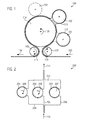
- the Fig. 1 exemplifies a system 100 for equipping liquid-filled containers.
- the system 100 may comprise a distributor device 104, which can direct containers to be printed to a plurality of equipment devices (101, 102, 103) and can discharge printed containers from the system 100 again.
- equipment devices 101, 102 designed as printing devices, and equipment device 103 as a labeling device e.g. Equipment devices 101, 102 designed as printing devices, and equipment device 103 as a labeling device.
- the distributor device 104 can be used as a rotary machine, e.g. as a rotary carousel, be carried out with a possible rotation or container circulation direction 109.
- the system 100 can be clocked or operated continuously, i. e.g. Process clocked or continuous container streams. Within a container stream containers can be treated individually and / or in groups (pulkweise) summarized.
- the equipment devices (101, 102, 103) can be designed, for example, as a rotary machine, as shown.
- the system 100 may process multiple container streams simultaneously. For illustration are in the Fig. 1
- two container streams 112, 113 are shown, which can be supplied to the system 100 from the direction 105 and, for example, can be transferred to the system 100 via a transfer star 107.
- Container streams may be independently controlled by a distribution device.
- container stream 112 may be distributed to the equipment device 101 and container stream 113 to the equipment device 102 from the distributor device 104.
- other (not shown) container flow partitions are also conceivable, for example, the distribution of a container stream to a further equipment device 103, or the forwarding of the same container stream to more than one equipment or treatment unit.
- another transfer star 108 can remove the containers that have been treated or treated by the system 100 and, for example, discharge them in the direction 106 and forward them to further process steps.
- the Fig. 2 exemplifies another system 200 for equipping liquid-filled containers.
- system 200 may include a distribution device 212 that may direct containers to be equipped to a plurality of equipment devices (201, 202, 203) and may discharge equipped containers from system 200 again.
- a distribution device 212 may direct containers to be equipped to a plurality of equipment devices (201, 202, 203) and may discharge equipped containers from system 200 again.
- the distributor device 212 may be designed as a linearly parallel distributor device 212, which may allow multiple container streams 204, 205, 206 to be processed in parallel and simultaneously.
- the equipment devices 201, 202, 203 can be designed, for example, as a rotary machine, as shown.
- the system 200 may also be clocked or continuously operated, i. e.g. Process clocked or continuous container streams.
- containers can be treated individually and / or in groups summarized (pulkweise).
- Container streams may be independently controlled by a distribution device.
- containers or container streams 204, 205, 206 supplied from the direction 210 can be distributed as follows.
- Container stream 204 may be distributed to equipment 201, container stream 205 to equipment 202, and container stream 206 to equipment 203. Subsequently, the container streams 204, 205, 206 can be removed in the direction 211 and forwarded to further process steps.
- container flow splits or container treatment sequences are also conceivable.
- the containers of the container streams 204, 205, 206 can pass through pretreatment units or after-treatment units (not shown) and / or other equipment (not shown).
- the distribution can be done, for example, in basehandling.
- the containers arrive on a common conveyor belt from direction 210 and can be divided by fixed rails into three container streams (204, 205, 206).
- the rails can also be controlled at your angle, so that the supplied containers can be further divided into two container streams or into a container stream.
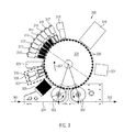
- the Fig. 3 exemplifies another system 300 for equipping, in particular for printing, containers 320 that can be filled with liquid.
- the system 300 may comprise a transporting element 304 designed as a distributor carousel, which can guide containers to be printed to a plurality of printing devices (307, 308 and 310, 311, 312, 313, 314, 315, 316, 317 and 319) and printed containers again can discharge from the system 300.
- a transporting element 304 designed as a distributor carousel, which can guide containers to be printed to a plurality of printing devices (307, 308 and 310, 311, 312, 313, 314, 315, 316, 317 and 319) and printed containers again can discharge from the system 300.
- Transport element 304 can be understood both as a distributor device or part of a distribution device, as well as a transport element of a fitting device.
- the printing devices may e.g. work with digital inkjet printing technology such as the printing devices 307, 308 and 310, 311, 312, 313, 314, 315, 316 and 317 shown here, or alternatively with alternative printing techniques, such as printing. with screen printing technique, e.g. Printing device 319.
- the system 300 may also include units for pre- or post-treatment of containers.
- a pretreatment unit 305 e.g. responsible for container orientation, and / or tempering and / or container surface modification etc., which prepare containers 320 of a container stream, which may be supplied to the system 300 from a main supply direction 301, for subsequent printing or treatment processes.
- a possible aftertreatment unit 321 can serve, for example, for image control by means of a camera, as shown here.
- system 300 may include aftertreatment units such as 309 and / or 318, e.g. for curing the printing / the print image by means of energy radiation such as UV light.
- the printing devices may also have integrated post-treatment units, for example an integrated ink curing unit, e.g. with UV light for digital inkjet printing.
- integrated post-treatment units for example an integrated ink curing unit, e.g. with UV light for digital inkjet printing.
- the printing devices can be designed as modules that can dock on a transport element 304.
- Modules may include at least one printing device.
- a module 306 is shown which may include the printing devices 307 and 308.
- modules may also include or include units for pre- or post-treatment of containers, consisting of individual devices or multiple devices.
- the modules can in particular be mounted on rollers and have fitting bores, which can be insertable into centering elements provided on the distributor.
- the modules can either be raised for operation via a drive arranged on the distributor carousel, so that they participate in the same vibrations as the distributor carousel or they can remain on the ground with their feet or rollers.
- the transport element 304 can be used as a rotary, e.g. as a rotary carousel, be carried out with a possible rotary or container rotation direction 303.
- the system 300 can be clocked or operated continuously, i. e.g. Process clocked or continuous container streams.
- Within a container flow containers 320 can be treated individually and / or in groups (pulkweise) summarized.
- Printing devices, pre- and post-treatment units can be docked individually, in groups and / or modularly on the distributor device 304. This allows a high flexibility or improvement in terms of performance and efficiency of the system 300, since, for example, as needed, the number and arrangement of the printing devices can be changed, and Pressure devices can be maintained without having to put the whole system 300 out of service.
- the containers 320 may be supplied to the system 300 via transfer stars 323, 322 by means of a distributor device 324 (301) or removed from the system 300 (302).
- a distribution can be performed such that only selected printing modules print the containers. It can be determined which containers are supplied to specific printing modules, or remain on these printing modules, and which are passed by certain printing modules. It may happen that similar printing modules, for example, with the same color, several times in the periphery of the Verteiler carousel 304 may be arranged.
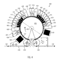
- the Fig. 4 exemplifies another system 400 for equipping, in particular printing, of containers 434 that can be filled with liquid, which, among other things, can have almost all the features of previously described system, in particular of the system 300.
- the system 400 may include a transport member 404 having containers to be printed on a plurality of printing devices (406, 407 and 409, 410, 411, 412, 413, 414, 415, 416 and 417, 418 and 419, 420, 421, 422 , 423, 424, 425, 426) and can discharge printed containers out of the system 400 again.
- a transport member 404 having containers to be printed on a plurality of printing devices (406, 407 and 409, 410, 411, 412, 413, 414, 415, 416 and 417, 418 and 419, 420, 421, 422 , 423, 424, 425, 426) and can discharge printed containers out of the system 400 again.
- Transport element 404 can be understood both as a distributor device or part of a distribution device, as well as a transport element of an equipment device.
- the printing devices may e.g. work with digital inkjet printing technology such as the printing devices 406 to 426 shown here, or alternatively with alternative printing techniques, such as e.g. with screen printing technique.
- the system 400 may also include units for pre- or post-treatment of containers.
- a pre-treatment unit 405 for example, responsible for container orientation, and / or temperature and / or container surface modification, etc., the container 434 of a container stream, which can be supplied to the system 400 from a main supply direction 401, prepare for subsequent printing or treatment processes.
- a possible aftertreatment unit 431 can serve, for example, for image control by means of a camera, as shown here.
- the system 400 may include aftertreatment units such as 408 and / or 428 and / or 429 and / or 427, e.g. for curing the printing / image by means of ultraviolet light (UV light).
- UV light ultraviolet light
- the printing devices may also have integrated post-treatment units, for example an integrated ink curing unit, e.g. with UV light for digital inkjet printing.
- integrated post-treatment units for example an integrated ink curing unit, e.g. with UV light for digital inkjet printing.
- the printing devices may be implemented as modules that may dock to a manifold device 404.
- Modules may include at least one printing device.
- modules may also include or include units for pre- or post-treatment of containers.
- the transport element 404 can be used as a rotary, e.g. as a rotary carousel, be designed with a possible rotary or container rotation direction 403.
- the system 400 may be clocked or continuously operated, i. e.g. Process clocked or continuous container streams.
- containers 434 can be treated individually and / or in groups (pulkweise) summarized.
- Printing devices, pre- and post-treatment units can be docked individually, in groups and / or modularly on the distributor device 404. This allows a high flexibility and / or improvement in performance and efficiency of the system 400, since, for example, the number and arrangement of the printing devices can be changed as required and printing devices can be maintained without having to decommission the entire system 400.
- the system 400 may include, inter alia, a blank 430 between printing devices and / or processing units, in which, for example, containers 434 may be rotated to e.g. allow a two-sided printing of the container.
- a particular empty field 430 may facilitate the rotation of containers, particularly in asymmetric and compared to the system bulky containers, without, for example, having to make restrictions on the compactness of the system 400 assembly.
- the containers 434 may be supplied to the system 400 via transfer stars or transfer units 433, 432 by means of a distributor device 435 (401) or removed from the system 400 (402).
- the Fig. 5 exemplifies another system 500 for equipping containers that can be filled with liquid.
- the system 500 may have features of systems described above.
- the system 500 may be modular in construction, with a module 501 e.g. an equipment device 508 and two transfer devices 509 and / or 510 for transfer or acceptance of containers between equipment 508 and distribution device 513 may have.
- a module 501 e.g. an equipment device 508 and two transfer devices 509 and / or 510 for transfer or acceptance of containers between equipment 508 and distribution device 513 may have.
- no transfer device can also be provided.
- the entry or removal of the containers from or into the equipment device may be e.g. a distributor device 513 / take a container transport element directly.
- Distributor device 513 may thus include containers 505, e.g. from a main movement direction 503 are supplied to the system 500, an equipment 508 by means of a transfer device 509 pass. After passing through the equipment device, which can be designed, for example, as a carousel with a direction of rotation or container circulation direction 507, a further transfer device 510 can transfer the containers 506 back to the distributor device 513, and transfer them, for example, to a further module 502 (indicated only schematically) analogously to FIG Forward first module 501 or pass this.
- a further transfer device 510 can transfer the containers 506 back to the distributor device 513, and transfer them, for example, to a further module 502 (indicated only schematically) analogously to FIG Forward first module 501 or pass this.
- the transfer devices 509, 510 may have grippers 511, 512, 517, 521, 518, 519 suitable for base handling and / or body handling and / or neck handling.
- the grippers can be designed, for example, as an outer gripper (as shown) and / or as an inner gripper.
- gripper movement paths 515, 516 are also shown by way of example.
- a gripper 521 can remove containers 505 of the distributor from a continuous barrel, so an escort route may be provided to give the gripper sufficient time to access.
- a second gripper 519 can grip a container from the equipment device 508, so that a place or container receptacle in the equipment device becomes free. In this free space can now be e.g. a container held by gripper 517 can be accurately inserted.
- enclosures 514 may shield the individual containers from each other on the equipment device 508 designed as a carousel.
- the equipment 508 is e.g.
- a printing device having multiple printing stations and / or ink curing stations may prevent enclosure, e.g. UV light can pass from an ink curing process at a station to an adjacent station, where, for example, printing is in progress and curing of the ink is not desired.
- the enclosure may e.g. consisting of two side walls between the stations, the equipment equipment table as a shielding downwards, and a wall (not shown), which cover the containers e.g. shields in the direction of the rotation axis of the carousel and a cover, not shown, for shielding upwards.
- the container can be freely accessible, both for the printheads of each station, as well as any drying or post-treatment or removal from the carousel.
- All elements of the enclosure can be arranged immovably on the carousel and rotate with it, without changing your position to the carousel.
- this simple enclosure requires a somewhat more complex point-like transfer of the containers through the grippers of the transfer device while accompanying them (until, for example, the snap of the pressure carousel has snapped), however, expensive movements of housing wall elements, for example, can thus be avoided.
- the Fig. 6 exemplifies another system 600 for equipping containers that can be filled with liquid.
- the system 600 can have features of systems described above.
- the arrow directions in the Figure 6 Container conveying directions or possible direction of rotation of transfer devices, carousels, equipment, etc.
- containers 616 to be equipped or to be treated from direction 601 can be supplied to the system 600.
- the containers 616 can first be transferred to a pretreatment unit 609, which can be located on a first distribution carousel 617.
- the containers can be transferred to a second distributor carousel 618 by transfer device 604.
- reservoirs 616 may be directed to equipment devices 610, 611, 612, 613, wherein the transfer of the reservoirs from second manifold carousel 618 to the respective equipment device may be accomplished with none, one, or two transfer devices.
- a transfer device 606, 606, 607, 608 for the transfer between distributor carousel 618 and the equipment devices 610, 611, 612, 613 is shown.
- the now equipped containers may e.g. be transferred by transfer device 614 again to the first distribution carousel 617, where they are e.g. can be treated by a post-treatment unit 615 before they can be transferred to another distribution system by means of transfer device 619 and can be removed from the system 600 in the direction 602.
- Equipment and pre- and post-treatment of the containers can thus be controlled via two separate distribution carousels.
- the container transport elements of the distributor carousel are equipped with container rotating devices, so that containers e.g. are rotatable in the direction of rotation 619.
- Distribution carousels 617 and 618 may be considered part of a distribution device 620.
- the Fig. 7 exemplifies another system 700 for equipping containers that can be filled with liquid.
- the system 700 may have features of systems described above.
- the arrow directions in the figure represent container conveying directions or possible direction of rotation of transfer devices, carousels, equipment devices, container rotations, etc.
- Containers 715 to be treated may be supplied to system 700 from direction 701.
- a transfer device 703 first of all, the containers can be transferred to a distribution device 717, which can initially convey the containers to a pretreatment unit 709.
- Distributor 717 may then then place the containers e.g. lead to equipment devices 710, 711, 712, 713, wherein the transfer of the containers between distribution device 717 and equipment devices 710, 711, 712, 713 can again take place with no, one or two transfer device (s), in which case in each case a transfer device 704, 705, 706, 707.
- the container transport elements of the distributor device 717 are equipped with container rotating devices, so that containers e.g. are rotatable in the direction of rotation 619.
- first a first side of the container e.g. the front side, being equipped by a first equipment device
- a second side of the container e.g. the back of a second equipment device.
Landscapes
- Engineering & Computer Science (AREA)
- Manufacturing & Machinery (AREA)
- Auxiliary Devices For And Details Of Packaging Control (AREA)
- Specific Conveyance Elements (AREA)
- Labeling Devices (AREA)
Applications Claiming Priority (1)
| Application Number | Priority Date | Filing Date | Title |
|---|---|---|---|
| DE102012213080.2A DE102012213080A1 (de) | 2012-07-25 | 2012-07-25 | Vorrichtung und Verfahren zum Ausstattung von Behältern - Basismaschine |
Publications (3)
| Publication Number | Publication Date |
|---|---|
| EP2689933A2 true EP2689933A2 (fr) | 2014-01-29 |
| EP2689933A3 EP2689933A3 (fr) | 2017-12-20 |
| EP2689933B1 EP2689933B1 (fr) | 2020-04-15 |
Family
ID=48875512
Family Applications (1)
| Application Number | Title | Priority Date | Filing Date |
|---|---|---|---|
| EP13176426.8A Active EP2689933B1 (fr) | 2012-07-25 | 2013-07-15 | Dispositif et procédé destinés à l'équipement de récipients et machine de base |
Country Status (3)
| Country | Link |
|---|---|
| EP (1) | EP2689933B1 (fr) |
| CN (1) | CN103569433B (fr) |
| DE (1) | DE102012213080A1 (fr) |
Cited By (7)
| Publication number | Priority date | Publication date | Assignee | Title |
|---|---|---|---|---|
| WO2015036334A1 (fr) * | 2013-09-13 | 2015-03-19 | Till Gmbh | Dispositif d'impression de récipients à symétrie de révolution |
| FR3057490A1 (fr) * | 2016-10-13 | 2018-04-20 | Machines Dubuit | Machine d'impression d'une pluralite d'objets au moins en partie tronconiques |
| WO2020126139A1 (fr) * | 2018-12-18 | 2020-06-25 | Krones Ag | Dispositif et procédé pour le traitement de contenants |
| EP3798158A1 (fr) * | 2019-09-30 | 2021-03-31 | Krones Ag | Dispositif de manipulation de conception modulaire pour récipients |
| WO2021063644A1 (fr) * | 2019-09-30 | 2021-04-08 | Krones Ag | Dispositif de traitement de récipients avec possibilité de maintenance lors d'une opération en cours |
| CN114590540A (zh) * | 2020-12-03 | 2022-06-07 | 克朗斯股份公司 | 容器处理方法 |
| EP3239079B1 (fr) * | 2016-04-25 | 2024-02-14 | Sidel Participations | Installation de manutention de corps creux, comprenant un convoyeur de distribution et des unites de traitement satellites |
Families Citing this family (16)
| Publication number | Priority date | Publication date | Assignee | Title |
|---|---|---|---|---|
| DE102014109948A1 (de) | 2014-07-16 | 2016-01-21 | Krones Ag | Verfahren und Vorrichtung zum Bedrucken von Behältern |
| DE102014112482A1 (de) * | 2014-08-29 | 2016-03-03 | Krones Aktiengesellschaft | Vorrichtung und Verfahren zum Ausstatten von Behältnissen |
| DE102014112483A1 (de) * | 2014-08-29 | 2016-03-03 | Krones Aktiengesellschaft | Vorrichtung und Verfahren zum Bedrucken von Behältnissen mit Fehlererfassung |
| JP6009001B2 (ja) * | 2015-01-15 | 2016-10-19 | 東洋製罐株式会社 | 容器の充填密封装置 |
| DE102015103654B4 (de) | 2015-03-12 | 2020-10-29 | Khs Gmbh | Etikettiervorrichtung für Behälter |
| DE102015215227A1 (de) | 2015-08-10 | 2017-02-16 | Krones Ag | Behälterbehandlungsmaschine und Verfahren zur Bedruckung von Behältern |
| DE102015215224A1 (de) | 2015-08-10 | 2017-02-16 | Krones Ag | Behälterbehandlungsmaschine und Verfahren zur Bedruckung von Behältern |
| DE102015219975A1 (de) * | 2015-10-14 | 2017-04-20 | Krones Ag | Verfahren zum individuellen Bedrucken von Behältern |
| DE202016100863U1 (de) | 2016-02-18 | 2017-05-26 | Krones Ag | Transportstern |
| DE102016002244B4 (de) * | 2016-02-26 | 2019-04-25 | Leibinger Gmbh | Bearbeitungsvorrichtung, Anlage und Bearbeitungsverfahren für Behälter unterschiedlicher Typen |
| DE102016212521A1 (de) | 2016-07-08 | 2018-01-11 | Krones Ag | Verfahren und Vorrichtung zum mehrfarbigen Tintenstrahldruck auf Behälter |
| DE102017215443A1 (de) * | 2017-09-04 | 2019-03-07 | Krones Ag | Rundläufermaschine zur Behandlung von Behältern |
| FR3090456B1 (fr) | 2018-12-19 | 2020-11-27 | Sidel Participations | Ligne de production de récipients controlée par un dispositif de détermination de position |
| DE102019106518A1 (de) * | 2019-03-14 | 2020-09-17 | Khs Gmbh | Vorrichtung und Verfahren zum Bedrucken von Behältern |
| DE102022122834A1 (de) | 2022-09-08 | 2024-03-14 | Krones Aktiengesellschaft | Herstellung und behandlung von behältern |
| CN115972757B (zh) * | 2022-12-30 | 2026-03-20 | 北京威顿(郓城)玻璃制品有限公司 | 一种玻璃瓶一体印花系统 |
Citations (2)
| Publication number | Priority date | Publication date | Assignee | Title |
|---|---|---|---|---|
| DE102004018189A1 (de) | 2004-04-08 | 2005-11-10 | Werner Kammann Maschinenfabrik Gmbh & Co. Kg | Vorrichtung zum Dekorieren von formsteifen Objekten mittels Siebdruck |
| DE102009013477B4 (de) | 2009-03-19 | 2012-01-12 | Khs Gmbh | Druckvorrichtung zum Bedrucken von Flaschen oder dergleichen Behältern |
Family Cites Families (12)
| Publication number | Priority date | Publication date | Assignee | Title |
|---|---|---|---|---|
| US4662965A (en) * | 1985-12-18 | 1987-05-05 | Owens-Illinois, Inc. | Adhering heat sensitive labels to containers with hot melt adhesives |
| DE19513064B4 (de) * | 1995-04-07 | 2004-04-01 | Khs Maschinen- Und Anlagenbau Ag | Verfahren sowie System zum Füllen von Behältern mit einem flüssigen Füllgut sowie Füllmaschine und Etikettiereinrichtung zur Verwendung bei diesem Verfahren oder System |
| DE10226500B4 (de) * | 2002-06-14 | 2010-04-22 | Ball Packaging Europe Holding Gmbh & Co. Kg | Vorrichtung zur Oberflächenbearbeitung von Teilen |
| US20050067111A1 (en) * | 2003-09-30 | 2005-03-31 | Mcc-Dec Tech, L.L.C. | System and associated method for high output label application |
| DE102008051791A1 (de) * | 2008-10-17 | 2010-04-22 | Khs Ag | Verfahren sowie Vorrichtung zum Ausstatten von Behältern |
| DE102009031479A1 (de) * | 2009-07-01 | 2011-01-05 | Krones Ag | Vorrichtung zum Anbringen von Etikettenstreifen an Behältnissen |
| DE102009043880A1 (de) * | 2009-08-21 | 2011-02-24 | Krones Ag | Einrichtung und Verfahren zum Etikettieren von Behältern mit unterschiedlichen Etikettentypen |
| DE102009040346A1 (de) * | 2009-09-09 | 2011-03-10 | Krones Ag | Etikettiervorrichtung und Etikettierverfahren zum Etikettieren von Behältnissen sowie Anlage zur Behandlung von Behältnissen |
| DE102010000548A1 (de) * | 2010-02-25 | 2011-08-25 | Krones Ag, 93073 | Transport- und Trocknungsstrecke für einzeln beförderte Artikel und Verfahren zur Trocknung einzeln beförderter Artikel |
| DE102010045661A1 (de) * | 2010-09-17 | 2012-03-22 | Khs Gmbh | Verfahren und Vorrichtung zum Ausstatten, insbesondere Etikettieren von Flaschen oder dergleichen Behältern |
| DE102010042165A1 (de) * | 2010-10-07 | 2012-04-12 | Krones Aktiengesellschaft | Verfahren zum Behandeln wenigstens eines Behälters in einer Behälterbehandlungsanlage |
| DE102011119966B3 (de) * | 2011-12-02 | 2012-11-22 | Khs Gmbh | Vorrichtung zur Bildung von Verpackungseinheiten |
-
2012
- 2012-07-25 DE DE102012213080.2A patent/DE102012213080A1/de not_active Ceased
-
2013
- 2013-07-15 EP EP13176426.8A patent/EP2689933B1/fr active Active
- 2013-07-25 CN CN201310317045.7A patent/CN103569433B/zh active Active
Patent Citations (2)
| Publication number | Priority date | Publication date | Assignee | Title |
|---|---|---|---|---|
| DE102004018189A1 (de) | 2004-04-08 | 2005-11-10 | Werner Kammann Maschinenfabrik Gmbh & Co. Kg | Vorrichtung zum Dekorieren von formsteifen Objekten mittels Siebdruck |
| DE102009013477B4 (de) | 2009-03-19 | 2012-01-12 | Khs Gmbh | Druckvorrichtung zum Bedrucken von Flaschen oder dergleichen Behältern |
Cited By (11)
| Publication number | Priority date | Publication date | Assignee | Title |
|---|---|---|---|---|
| WO2015036334A1 (fr) * | 2013-09-13 | 2015-03-19 | Till Gmbh | Dispositif d'impression de récipients à symétrie de révolution |
| EP3239079B1 (fr) * | 2016-04-25 | 2024-02-14 | Sidel Participations | Installation de manutention de corps creux, comprenant un convoyeur de distribution et des unites de traitement satellites |
| FR3057490A1 (fr) * | 2016-10-13 | 2018-04-20 | Machines Dubuit | Machine d'impression d'une pluralite d'objets au moins en partie tronconiques |
| WO2020126139A1 (fr) * | 2018-12-18 | 2020-06-25 | Krones Ag | Dispositif et procédé pour le traitement de contenants |
| JP2022510054A (ja) * | 2018-12-18 | 2022-01-26 | クロネス アーゲー | 容器を処理するための装置および方法 |
| US11939200B2 (en) | 2018-12-18 | 2024-03-26 | Krones Ag | Apparatus and method for treating containers |
| EP3798158A1 (fr) * | 2019-09-30 | 2021-03-31 | Krones Ag | Dispositif de manipulation de conception modulaire pour récipients |
| WO2021063644A1 (fr) * | 2019-09-30 | 2021-04-08 | Krones Ag | Dispositif de traitement de récipients avec possibilité de maintenance lors d'une opération en cours |
| EP3798158B1 (fr) | 2019-09-30 | 2023-11-15 | Krones Ag | Dispositif de manipulation de conception modulaire pour récipients |
| US11834217B2 (en) | 2019-09-30 | 2023-12-05 | Krones Ag | Modular treatment apparatus for containers |
| CN114590540A (zh) * | 2020-12-03 | 2022-06-07 | 克朗斯股份公司 | 容器处理方法 |
Also Published As
| Publication number | Publication date |
|---|---|
| CN103569433B (zh) | 2016-04-06 |
| EP2689933A3 (fr) | 2017-12-20 |
| CN103569433A (zh) | 2014-02-12 |
| EP2689933B1 (fr) | 2020-04-15 |
| DE102012213080A1 (de) | 2014-01-30 |
Similar Documents
| Publication | Publication Date | Title |
|---|---|---|
| EP2689933B1 (fr) | Dispositif et procédé destinés à l'équipement de récipients et machine de base | |
| EP2661374B1 (fr) | Machine pour imprimer des recipients | |
| EP2331338B1 (fr) | Dispositif pour appliquer de multiples impressions sur un matériau d'emballage | |
| EP2512812B1 (fr) | Installation destinée à l'impression de récipients | |
| DE102009058222B4 (de) | Anlage zum Bedrucken von Behältern mit Einspannvorrichtungen mit eigenem Drehantrieb | |
| DE102009040363A1 (de) | Vorrichtung und Verfahren zum Herstellen von Kunststoffflaschen | |
| DE102013214934A1 (de) | Vorrichtung und Verfahren zum Direktbedrucken von Behältern | |
| DE102010034780A1 (de) | Vorrichtung und Verfahren zum Bedrucken von Behältern | |
| CN104275922A (zh) | 容器印刷设备和方法 | |
| DE202009018193U1 (de) | Vorrichtung zum Behandeln von Packmitteln | |
| EP2797834B1 (fr) | Dispositif et procédé pour remplir, fermer et étiqueter des récipients | |
| DE102018132608A1 (de) | Vorrichtung und Verfahren zum Behandeln von Behältnissen | |
| DE102008062580A1 (de) | Maschine zum Ausstatten von Artikeln und Verfahren zur Steuerung der Maschine | |
| EP3098081A1 (fr) | Dispositif et procédé d'impression numérique sur des articles | |
| EP4559848A2 (fr) | Transport d'articles de formats differents | |
| DE102015211770A1 (de) | Vorrichtung und Verfahren zum Bedrucken von Behälterverschlüssen | |
| EP3674439A1 (fr) | Dispositif et procédé de revêtement de récipients | |
| DE102020120284A1 (de) | Vorrichtung zur Behandlung von Behälterrohlingen | |
| DE102019126402A1 (de) | Vorrichtung und Verfahren zum Befüllen von Behältnissen | |
| EP3689761B1 (fr) | Dispositif et procédé de manipulation et / ou d'emballage d'articles | |
| WO2023198441A1 (fr) | Système de traitement de récipients | |
| DE102020132134A1 (de) | Direktdruckmaschine | |
| EP4508000A1 (fr) | Système de traitement de récipients | |
| EP1655227A1 (fr) | Dispositif pour déballer de conteneurs hors de la caisse de transport | |
| EP3341205A1 (fr) | Système de traitement de récipients muni d'un dispositif pour remplacer des unités de retenue et de centrage |
Legal Events
| Date | Code | Title | Description |
|---|---|---|---|
| PUAI | Public reference made under article 153(3) epc to a published international application that has entered the european phase |
Free format text: ORIGINAL CODE: 0009012 |
|
| AK | Designated contracting states |
Kind code of ref document: A2 Designated state(s): AL AT BE BG CH CY CZ DE DK EE ES FI FR GB GR HR HU IE IS IT LI LT LU LV MC MK MT NL NO PL PT RO RS SE SI SK SM TR |
|
| AX | Request for extension of the european patent |
Extension state: BA ME |
|
| PUAL | Search report despatched |
Free format text: ORIGINAL CODE: 0009013 |
|
| AK | Designated contracting states |
Kind code of ref document: A3 Designated state(s): AL AT BE BG CH CY CZ DE DK EE ES FI FR GB GR HR HU IE IS IT LI LT LU LV MC MK MT NL NO PL PT RO RS SE SI SK SM TR |
|
| AX | Request for extension of the european patent |
Extension state: BA ME |
|
| RIC1 | Information provided on ipc code assigned before grant |
Ipc: B41J 3/407 20060101AFI20171113BHEP |
|
| STAA | Information on the status of an ep patent application or granted ep patent |
Free format text: STATUS: REQUEST FOR EXAMINATION WAS MADE |
|
| 17P | Request for examination filed |
Effective date: 20180619 |
|
| RBV | Designated contracting states (corrected) |
Designated state(s): AL AT BE BG CH CY CZ DE DK EE ES FI FR GB GR HR HU IE IS IT LI LT LU LV MC MK MT NL NO PL PT RO RS SE SI SK SM TR |
|
| GRAP | Despatch of communication of intention to grant a patent |
Free format text: ORIGINAL CODE: EPIDOSNIGR1 |
|
| STAA | Information on the status of an ep patent application or granted ep patent |
Free format text: STATUS: GRANT OF PATENT IS INTENDED |
|
| INTG | Intention to grant announced |
Effective date: 20200204 |
|
| GRAS | Grant fee paid |
Free format text: ORIGINAL CODE: EPIDOSNIGR3 |
|
| GRAA | (expected) grant |
Free format text: ORIGINAL CODE: 0009210 |
|
| STAA | Information on the status of an ep patent application or granted ep patent |
Free format text: STATUS: THE PATENT HAS BEEN GRANTED |
|
| AK | Designated contracting states |
Kind code of ref document: B1 Designated state(s): AL AT BE BG CH CY CZ DE DK EE ES FI FR GB GR HR HU IE IS IT LI LT LU LV MC MK MT NL NO PL PT RO RS SE SI SK SM TR |
|
| REG | Reference to a national code |
Ref country code: CH Ref legal event code: EP Ref country code: GB Ref legal event code: FG4D Free format text: NOT ENGLISH |
|
| REG | Reference to a national code |
Ref country code: DE Ref legal event code: R096 Ref document number: 502013014575 Country of ref document: DE |
|
| REG | Reference to a national code |
Ref country code: IE Ref legal event code: FG4D Free format text: LANGUAGE OF EP DOCUMENT: GERMAN |
|
| REG | Reference to a national code |
Ref country code: AT Ref legal event code: REF Ref document number: 1256811 Country of ref document: AT Kind code of ref document: T Effective date: 20200515 |
|
| REG | Reference to a national code |
Ref country code: NL Ref legal event code: MP Effective date: 20200415 |
|
| REG | Reference to a national code |
Ref country code: LT Ref legal event code: MG4D |
|
| PG25 | Lapsed in a contracting state [announced via postgrant information from national office to epo] |
Ref country code: IS Free format text: LAPSE BECAUSE OF FAILURE TO SUBMIT A TRANSLATION OF THE DESCRIPTION OR TO PAY THE FEE WITHIN THE PRESCRIBED TIME-LIMIT Effective date: 20200815 Ref country code: FI Free format text: LAPSE BECAUSE OF FAILURE TO SUBMIT A TRANSLATION OF THE DESCRIPTION OR TO PAY THE FEE WITHIN THE PRESCRIBED TIME-LIMIT Effective date: 20200415 Ref country code: NO Free format text: LAPSE BECAUSE OF FAILURE TO SUBMIT A TRANSLATION OF THE DESCRIPTION OR TO PAY THE FEE WITHIN THE PRESCRIBED TIME-LIMIT Effective date: 20200715 Ref country code: GR Free format text: LAPSE BECAUSE OF FAILURE TO SUBMIT A TRANSLATION OF THE DESCRIPTION OR TO PAY THE FEE WITHIN THE PRESCRIBED TIME-LIMIT Effective date: 20200716 Ref country code: SE Free format text: LAPSE BECAUSE OF FAILURE TO SUBMIT A TRANSLATION OF THE DESCRIPTION OR TO PAY THE FEE WITHIN THE PRESCRIBED TIME-LIMIT Effective date: 20200415 Ref country code: NL Free format text: LAPSE BECAUSE OF FAILURE TO SUBMIT A TRANSLATION OF THE DESCRIPTION OR TO PAY THE FEE WITHIN THE PRESCRIBED TIME-LIMIT Effective date: 20200415 Ref country code: LT Free format text: LAPSE BECAUSE OF FAILURE TO SUBMIT A TRANSLATION OF THE DESCRIPTION OR TO PAY THE FEE WITHIN THE PRESCRIBED TIME-LIMIT Effective date: 20200415 Ref country code: PT Free format text: LAPSE BECAUSE OF FAILURE TO SUBMIT A TRANSLATION OF THE DESCRIPTION OR TO PAY THE FEE WITHIN THE PRESCRIBED TIME-LIMIT Effective date: 20200817 |
|
| PG25 | Lapsed in a contracting state [announced via postgrant information from national office to epo] |
Ref country code: BG Free format text: LAPSE BECAUSE OF FAILURE TO SUBMIT A TRANSLATION OF THE DESCRIPTION OR TO PAY THE FEE WITHIN THE PRESCRIBED TIME-LIMIT Effective date: 20200715 Ref country code: HR Free format text: LAPSE BECAUSE OF FAILURE TO SUBMIT A TRANSLATION OF THE DESCRIPTION OR TO PAY THE FEE WITHIN THE PRESCRIBED TIME-LIMIT Effective date: 20200415 Ref country code: LV Free format text: LAPSE BECAUSE OF FAILURE TO SUBMIT A TRANSLATION OF THE DESCRIPTION OR TO PAY THE FEE WITHIN THE PRESCRIBED TIME-LIMIT Effective date: 20200415 Ref country code: RS Free format text: LAPSE BECAUSE OF FAILURE TO SUBMIT A TRANSLATION OF THE DESCRIPTION OR TO PAY THE FEE WITHIN THE PRESCRIBED TIME-LIMIT Effective date: 20200415 |
|
| PG25 | Lapsed in a contracting state [announced via postgrant information from national office to epo] |
Ref country code: AL Free format text: LAPSE BECAUSE OF FAILURE TO SUBMIT A TRANSLATION OF THE DESCRIPTION OR TO PAY THE FEE WITHIN THE PRESCRIBED TIME-LIMIT Effective date: 20200415 |
|
| REG | Reference to a national code |
Ref country code: DE Ref legal event code: R097 Ref document number: 502013014575 Country of ref document: DE |
|
| PG25 | Lapsed in a contracting state [announced via postgrant information from national office to epo] |
Ref country code: ES Free format text: LAPSE BECAUSE OF FAILURE TO SUBMIT A TRANSLATION OF THE DESCRIPTION OR TO PAY THE FEE WITHIN THE PRESCRIBED TIME-LIMIT Effective date: 20200415 Ref country code: DK Free format text: LAPSE BECAUSE OF FAILURE TO SUBMIT A TRANSLATION OF THE DESCRIPTION OR TO PAY THE FEE WITHIN THE PRESCRIBED TIME-LIMIT Effective date: 20200415 Ref country code: RO Free format text: LAPSE BECAUSE OF FAILURE TO SUBMIT A TRANSLATION OF THE DESCRIPTION OR TO PAY THE FEE WITHIN THE PRESCRIBED TIME-LIMIT Effective date: 20200415 Ref country code: SM Free format text: LAPSE BECAUSE OF FAILURE TO SUBMIT A TRANSLATION OF THE DESCRIPTION OR TO PAY THE FEE WITHIN THE PRESCRIBED TIME-LIMIT Effective date: 20200415 Ref country code: EE Free format text: LAPSE BECAUSE OF FAILURE TO SUBMIT A TRANSLATION OF THE DESCRIPTION OR TO PAY THE FEE WITHIN THE PRESCRIBED TIME-LIMIT Effective date: 20200415 Ref country code: CZ Free format text: LAPSE BECAUSE OF FAILURE TO SUBMIT A TRANSLATION OF THE DESCRIPTION OR TO PAY THE FEE WITHIN THE PRESCRIBED TIME-LIMIT Effective date: 20200415 |
|
| PLBE | No opposition filed within time limit |
Free format text: ORIGINAL CODE: 0009261 |
|
| STAA | Information on the status of an ep patent application or granted ep patent |
Free format text: STATUS: NO OPPOSITION FILED WITHIN TIME LIMIT |
|
| PG25 | Lapsed in a contracting state [announced via postgrant information from national office to epo] |
Ref country code: MC Free format text: LAPSE BECAUSE OF FAILURE TO SUBMIT A TRANSLATION OF THE DESCRIPTION OR TO PAY THE FEE WITHIN THE PRESCRIBED TIME-LIMIT Effective date: 20200415 Ref country code: PL Free format text: LAPSE BECAUSE OF FAILURE TO SUBMIT A TRANSLATION OF THE DESCRIPTION OR TO PAY THE FEE WITHIN THE PRESCRIBED TIME-LIMIT Effective date: 20200415 Ref country code: SK Free format text: LAPSE BECAUSE OF FAILURE TO SUBMIT A TRANSLATION OF THE DESCRIPTION OR TO PAY THE FEE WITHIN THE PRESCRIBED TIME-LIMIT Effective date: 20200415 |
|
| REG | Reference to a national code |
Ref country code: CH Ref legal event code: PL |
|
| 26N | No opposition filed |
Effective date: 20210118 |
|
| GBPC | Gb: european patent ceased through non-payment of renewal fee |
Effective date: 20200715 |
|
| REG | Reference to a national code |
Ref country code: BE Ref legal event code: MM Effective date: 20200731 |
|
| PG25 | Lapsed in a contracting state [announced via postgrant information from national office to epo] |
Ref country code: LU Free format text: LAPSE BECAUSE OF NON-PAYMENT OF DUE FEES Effective date: 20200715 Ref country code: GB Free format text: LAPSE BECAUSE OF NON-PAYMENT OF DUE FEES Effective date: 20200715 Ref country code: CH Free format text: LAPSE BECAUSE OF NON-PAYMENT OF DUE FEES Effective date: 20200731 Ref country code: LI Free format text: LAPSE BECAUSE OF NON-PAYMENT OF DUE FEES Effective date: 20200731 |
|
| PG25 | Lapsed in a contracting state [announced via postgrant information from national office to epo] |
Ref country code: SI Free format text: LAPSE BECAUSE OF FAILURE TO SUBMIT A TRANSLATION OF THE DESCRIPTION OR TO PAY THE FEE WITHIN THE PRESCRIBED TIME-LIMIT Effective date: 20200415 Ref country code: BE Free format text: LAPSE BECAUSE OF NON-PAYMENT OF DUE FEES Effective date: 20200731 |
|
| PG25 | Lapsed in a contracting state [announced via postgrant information from national office to epo] |
Ref country code: IE Free format text: LAPSE BECAUSE OF NON-PAYMENT OF DUE FEES Effective date: 20200715 |
|
| REG | Reference to a national code |
Ref country code: AT Ref legal event code: MM01 Ref document number: 1256811 Country of ref document: AT Kind code of ref document: T Effective date: 20200715 |
|
| PG25 | Lapsed in a contracting state [announced via postgrant information from national office to epo] |
Ref country code: AT Free format text: LAPSE BECAUSE OF NON-PAYMENT OF DUE FEES Effective date: 20200715 |
|
| PG25 | Lapsed in a contracting state [announced via postgrant information from national office to epo] |
Ref country code: TR Free format text: LAPSE BECAUSE OF FAILURE TO SUBMIT A TRANSLATION OF THE DESCRIPTION OR TO PAY THE FEE WITHIN THE PRESCRIBED TIME-LIMIT Effective date: 20200415 Ref country code: MT Free format text: LAPSE BECAUSE OF FAILURE TO SUBMIT A TRANSLATION OF THE DESCRIPTION OR TO PAY THE FEE WITHIN THE PRESCRIBED TIME-LIMIT Effective date: 20200415 Ref country code: CY Free format text: LAPSE BECAUSE OF FAILURE TO SUBMIT A TRANSLATION OF THE DESCRIPTION OR TO PAY THE FEE WITHIN THE PRESCRIBED TIME-LIMIT Effective date: 20200415 |
|
| PG25 | Lapsed in a contracting state [announced via postgrant information from national office to epo] |
Ref country code: MK Free format text: LAPSE BECAUSE OF FAILURE TO SUBMIT A TRANSLATION OF THE DESCRIPTION OR TO PAY THE FEE WITHIN THE PRESCRIBED TIME-LIMIT Effective date: 20200415 |
|
| P01 | Opt-out of the competence of the unified patent court (upc) registered |
Effective date: 20230523 |
|
| PGFP | Annual fee paid to national office [announced via postgrant information from national office to epo] |
Ref country code: FR Payment date: 20250610 Year of fee payment: 13 |
|
| PGFP | Annual fee paid to national office [announced via postgrant information from national office to epo] |
Ref country code: DE Payment date: 20250604 Year of fee payment: 13 |
|
| PGFP | Annual fee paid to national office [announced via postgrant information from national office to epo] |
Ref country code: IT Payment date: 20250623 Year of fee payment: 13 |