EP2690697B1 - Zylindrische batterie und elektrodenstruktur für die batterie - Google Patents
Zylindrische batterie und elektrodenstruktur für die batterie Download PDFInfo
- Publication number
- EP2690697B1 EP2690697B1 EP12764292.4A EP12764292A EP2690697B1 EP 2690697 B1 EP2690697 B1 EP 2690697B1 EP 12764292 A EP12764292 A EP 12764292A EP 2690697 B1 EP2690697 B1 EP 2690697B1
- Authority
- EP
- European Patent Office
- Prior art keywords
- electrode assembly
- electrode plate
- positive
- positive electrode
- negative electrode
- Prior art date
- Legal status (The legal status is an assumption and is not a legal conclusion. Google has not performed a legal analysis and makes no representation as to the accuracy of the status listed.)
- Not-in-force
Links
Images


Classifications
-
- H—ELECTRICITY
- H01—ELECTRIC ELEMENTS
- H01M—PROCESSES OR MEANS, e.g. BATTERIES, FOR THE DIRECT CONVERSION OF CHEMICAL ENERGY INTO ELECTRICAL ENERGY
- H01M10/00—Secondary cells; Manufacture thereof
- H01M10/04—Construction or manufacture in general
- H01M10/0431—Cells with wound or folded electrodes
-
- H—ELECTRICITY
- H01—ELECTRIC ELEMENTS
- H01M—PROCESSES OR MEANS, e.g. BATTERIES, FOR THE DIRECT CONVERSION OF CHEMICAL ENERGY INTO ELECTRICAL ENERGY
- H01M4/00—Electrodes
- H01M4/02—Electrodes composed of, or comprising, active material
- H01M4/13—Electrodes for accumulators with non-aqueous electrolyte, e.g. for lithium-accumulators; Processes of manufacture thereof
-
- H—ELECTRICITY
- H01—ELECTRIC ELEMENTS
- H01M—PROCESSES OR MEANS, e.g. BATTERIES, FOR THE DIRECT CONVERSION OF CHEMICAL ENERGY INTO ELECTRICAL ENERGY
- H01M4/00—Electrodes
- H01M4/02—Electrodes composed of, or comprising, active material
- H01M4/64—Carriers or collectors
- H01M4/66—Selection of materials
- H01M4/661—Metal or alloys, e.g. alloy coatings
-
- H—ELECTRICITY
- H01—ELECTRIC ELEMENTS
- H01M—PROCESSES OR MEANS, e.g. BATTERIES, FOR THE DIRECT CONVERSION OF CHEMICAL ENERGY INTO ELECTRICAL ENERGY
- H01M50/00—Constructional details or processes of manufacture of the non-active parts of electrochemical cells other than fuel cells, e.g. hybrid cells
- H01M50/10—Primary casings; Jackets or wrappings
- H01M50/102—Primary casings; Jackets or wrappings characterised by their shape or physical structure
- H01M50/107—Primary casings; Jackets or wrappings characterised by their shape or physical structure having curved cross-section, e.g. round or elliptic
-
- H—ELECTRICITY
- H01—ELECTRIC ELEMENTS
- H01M—PROCESSES OR MEANS, e.g. BATTERIES, FOR THE DIRECT CONVERSION OF CHEMICAL ENERGY INTO ELECTRICAL ENERGY
- H01M50/00—Constructional details or processes of manufacture of the non-active parts of electrochemical cells other than fuel cells, e.g. hybrid cells
- H01M50/40—Separators; Membranes; Diaphragms; Spacing elements inside cells
- H01M50/46—Separators, membranes or diaphragms characterised by their combination with electrodes
-
- Y—GENERAL TAGGING OF NEW TECHNOLOGICAL DEVELOPMENTS; GENERAL TAGGING OF CROSS-SECTIONAL TECHNOLOGIES SPANNING OVER SEVERAL SECTIONS OF THE IPC; TECHNICAL SUBJECTS COVERED BY FORMER USPC CROSS-REFERENCE ART COLLECTIONS [XRACs] AND DIGESTS
- Y02—TECHNOLOGIES OR APPLICATIONS FOR MITIGATION OR ADAPTATION AGAINST CLIMATE CHANGE
- Y02E—REDUCTION OF GREENHOUSE GAS [GHG] EMISSIONS, RELATED TO ENERGY GENERATION, TRANSMISSION OR DISTRIBUTION
- Y02E60/00—Enabling technologies; Technologies with a potential or indirect contribution to GHG emissions mitigation
- Y02E60/10—Energy storage using batteries
-
- Y—GENERAL TAGGING OF NEW TECHNOLOGICAL DEVELOPMENTS; GENERAL TAGGING OF CROSS-SECTIONAL TECHNOLOGIES SPANNING OVER SEVERAL SECTIONS OF THE IPC; TECHNICAL SUBJECTS COVERED BY FORMER USPC CROSS-REFERENCE ART COLLECTIONS [XRACs] AND DIGESTS
- Y02—TECHNOLOGIES OR APPLICATIONS FOR MITIGATION OR ADAPTATION AGAINST CLIMATE CHANGE
- Y02P—CLIMATE CHANGE MITIGATION TECHNOLOGIES IN THE PRODUCTION OR PROCESSING OF GOODS
- Y02P70/00—Climate change mitigation technologies in the production process for final industrial or consumer products
- Y02P70/50—Manufacturing or production processes characterised by the final manufactured product
Definitions
- the present invention relates to a cylindrical battery.
- a cylindrical battery for an alkaline secondary battery such as a nickel-cadmium battery or a nickel-metal hydride battery
- a positive electrode plate and a negative electrode plate each having a belt shape are wounded spirally with a separator being interposed to form an electrode assembly and the electrode assembly is accommodated and sealed in a cylindrical battery case (referred to as a battery outer case or a container).
- a battery case accommodates the columnar electrode assembly obtained by spirally winding the positive electrode plate and the negative electrode plate in the belt shapes with the separator being interposed so as to be almost solid in the battery case.
- the applicant of the present invention has been developing a cylindrical battery of low capacity, which corresponds to a purpose of use. More specifically, the applicant of the present invention has been trying to reduce the number of times of spirally winding the positive electrode plate and the negative electrode plate in the belt shapes and accommodate the cylindrical electrode assembly in the battery case.
- a cylindrical battery according to the preamble of claim 1 is known from Patent Document 2. Similar cylindrical batteries are known from Patent Documents 3 and 4.
- the present invention has been achieved in order to collectively solve the problems, and it is a mainly expected object thereof is to prevent distortion in the wound shape due to the difference in height at the initially wound portion and to prevent tears in the electrode due to the difference in height at the initially wound portion in the cylindrical electrode assembly.
- a cylindrical battery according to the present invention is defined in independent claim 1.
- the electrode assembly is provided with the slit extending from the first axial end to the second axial end. It is thus possible to eliminate the difference in height at the initially wound portion so as to suppress distortion in the wound shape due to the initially wound portion and tears in the electrode due to deterioration at the electrode portion overlapped with the initially wound portion.
- Provision of the slit indicates that one continuous electrode has an initially wound end and lastly wound end forming a circumferential angle of less than 360 degrees.
- the single continuous electrode does not have any overlapped portion, but there is a gap between the initially wound end and the lastly wound end of the electrode.
- the conventional electrode assembly spirally wound has an outer diameter that is almost determined at the stage of winding. It is because the outer diameter cannot be easily expanded or contracted due to friction between the adjacent plates. If the outer diameter of the electrode assembly is smaller than the inner diameter of the battery case, the outermost portion of the electrode assembly is not sufficiently in contact with the inner circumferential surface of the battery case, thereby leading to deterioration in charge-discharge efficiency. If the outer diameter of the electrode assembly is larger than the inner diameter of the battery case, it is difficult to accommodate the electrode assembly in the battery case, and the active material held at the outermost plate in the electrode assembly may be scraped by the battery case, for example.
- the slit extending from the first axial end to the second axial end in the electrode assembly facilitates expansion and contraction in outer diameter of the electrode assembly.
- the electrode assembly By expanding the outer diameter of the electrode assembly in the state where the electrode assembly is arranged in the battery case, the electrode assembly can be easily pressed against the inner circumferential surface of the battery case, thereby inhibiting deterioration in charge-discharge efficiency. If the electrode assembly is reduced in diameter upon inserting the electrode assembly into the battery case, the electrode assembly can be arranged in the battery case with no damage to the electrode assembly.
- the electrode assembly preferably has a linear slit axially extending from the first axial end to the second axial end.
- the positive electrode and the negative electrode form a C shape in a cross section because of the slit axially extending from the first axial end to the second axial end, and the positive electrode and the negative electrode in the electrode assembly are arranged with the separator being interposed such that the slits thereof communicate each other.
- the positive electrode and the negative electrode are expanded and contracted around the portions facing the slits, so as to have expansion/contraction centers at substantially same positions. This reduces relative shift between the positive electrode and the negative electrode and thus reduces slippage.
- the slit of the electrode assembly significantly facilitates expansion and contraction. As the slit of the positive electrode and the slit of the negative electrode are located so as to communicate each other, the slits can be located as to orient in a same direction, for example.
- the electrode assembly can be configured such that a small number of (one to three) positive electrodes and a small number of (one to three) negative electrodes are concentrically and alternately arranged with separators being interposed respectively.
- the electrode assembly can be configured such that one positive electrode wound once and one negative electrode wound once are concentrically arranged with a separator being interposed.
- Such an electrode wound once has a hollow portion to allow the electrode assembly to be significantly loosened in accordance with charge and discharge.
- the electrode wound once is relatively thick, so as to press a case surface with larger force. When pressure against the case surface is large, an electrode is easily torn due to a difference in height at the initially wound portion.
- the effect of providing the slit in order to eliminate the difference in height at the initially wound portion is thus significant.
- the electrode assembly can be reduced in strength and be expanded and contracted in outer diameter more easily.
- the present invention is particularly useful for a battery used in a device that is operated with a battery of relatively low capacity (e.g., a remote controller).
- the battery for this purpose is typically configured without adopting any technique for reducing internal resistance. It is preferred in view of the number of components that the electrode case and an outermost electrode are made in contact with each other without adopting any technique of welding a current collector to an end of an outermost plate or any technique of attaching a tape to an end of the electrode in order to prevent increase in diameter of the electrode assembly having been inserted into the case.
- An electrode wound for a plurality of times achieves an electrode assembly that includes at least two negative electrodes and at least two continuous positive electrodes.
- An electrolyte solution preferably has a high concentration in view of a utilization factor of the active material.
- the concentration of KOH in the electrolyte solution can be raised from 7 M to 8 M.
- the area of a negative electrode relative to a positive electrode is smaller than a conventional one, thereby possibly leading to increase in internal resistance and deterioration in utilization factor of an active material.
- the electrolyte solution of a higher concentration suppresses deterioration in utilization factor of the active material.
- a holder member arranged in a hollow portion of the electrode assembly, between the positive electrode and the separator, and optionally between the negative electrode and the separator, for pressing the electrode assembly from inside to hold the electrode assembly.
- the holder member presses the electrode assembly from inside. It is thus possible to prevent separation of the active material due to the positive electrode or the negative electrode loosened inward and prevent deterioration in current collection efficiency.
- the positive electrode or the negative electrode is loosened more significantly if the hollow portion is provided.
- the holder member holds the electrode assembly of which outer circumferential surface is pressed against the inner circumferential surface of the battery case.
- the holder member is arranged in the hollow portion of the electrode assembly and presses the entire inner circumferential surface of the electrode assembly.
- the holder member is configured by an elastic plate and is deformed into a cylindrical shape so as to be arranged in the hollow portion of the electrode assembly, between the positive electrode and the separator, or between the negative electrode and the separator.
- the holder member thus located presses the electrode assembly from inside with elastic restoring force thereof, so as to hold the electrode assembly of which outer circumferential surface is pressed against the inner circumferential surface of the battery case.
- the innermost positive or negative electrode can be pressed against the battery case with the elastic restoring force so as to prevent separation of the active material and cause the outer circumferential surface of the electrode assembly and the inner circumferential surface of the battery case to be reliably pressed against each other.
- the plate can be fitted to the hollow portion of the electrode assembly in any size by simply deforming the plate into a cylindrical shape in any size.
- Each of the positive electrode and the negative electrode according to a specific aspect can include a current collector substrate.
- the current collector substrate thus provided follows variation in volume of the active material in accordance with charge and discharge, thereby keeping low electric resistance.
- the current collector substrate is elastic and presses the electrode assembly.
- at least the negative electrode includes a current collector substrate, which is elastic and presses the electrode assembly. In this configuration, the electrode assembly can be pressed by the current collector substrate without providing the holder member. It is thus possible to prevent separation of the active material due to the loosened positive or negative electrode and thus prevent deterioration in current collection efficiency.
- the electrode assembly is provided with the slit extending from the first axial end to the second axial end, it is possible to eliminate the difference in height at the initially wound portion so as to suppress distortion in the wound shape due to the initially wound portion and tears in the electrode due to deterioration at the electrode portion overlapped with the initially wound portion.
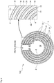
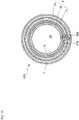
- a secondary battery 100 is an alkaline secondary battery such as a nickel-cadmium battery or a nickel-metal hydride battery. More specifically, the secondary battery 100 is a cylindrical battery of a low capacity type in which a AA battery has a capacity of not more than 1800 mAh or a AAA battery has a capacity of not more than 650 mAh, for example. As shown in Figs. 1 and 2 , the secondary battery 100 includes a metal battery case 2 in a bottomed cylindrical shape and a cylindrical electrode assembly 3 arranged in the battery case 2 and including positive electrode plates 31, negative electrode plates 32, and separators 33.
- the battery case 2 is coated with nickel and has a bottomed cylindrical shape. As shown in Fig. 1 , the battery case 2 has an upper opening that is sealed with a sealing member 5 with an insulating member 4 being interposed.
- the sealing member 5 has a rear surface at which a lead piece 311L projecting from the upper end of the positive electrode plate 31 is connected by, e.g., welding directly or by way of a current collecting plate (not shown), so that the sealing member 5 functions as a positive terminal.
- an inner circumferential surface 2m of the battery case 2 is in contact with an outer circumferential surface 3n of the negative electrode plate 32 located at the outermost circumference of the electrode assembly 3 (see the partial enlarged view in Fig. 2 ).
- the remaining negative electrode plate 32 is connected to the battery case 2 by way of a current collecting plate (not shown), so that the battery case 2 itself functions as a negative terminal.
- the electrode assembly 3 has a cylindrical shape and includes the positive electrode plates 31 and the negative electrode plates 32 that are concentrically and alternately located with the separators 33, which are nonwoven fabric made of, e.g., polyolefin, being interposed.
- Each of the separators includes an electrolyte solution of, e.g., potassium hydroxide impregnated therein.
- the positive electrode plate 31 includes a positive current collector of a punched steel plate coated with, e.g., nickel plating and a positive active material applied on the positive current collector.
- the positive current collector substrate has a substrate that can be made of foamed nickel. Foamed nickel exerts excellent current collection efficiency.
- the positive active material can be nickel hydroxide in the case of a nickel-cadmium battery, and can be nickel hydroxide including calcium hydroxide added thereto in the case of a nickel-metal hydride battery.
- the negative electrode plate 32 includes a negative current collector of a punched steel plate coated with nickel plating similarly to the positive electrode plates 31 and a negative active material applied on the negative current collector.
- the negative active material can be a mixture of a cadmium oxide powder and a metal cadmium powder in the case of a nickel-cadmium battery, and can be mainly a hydrogen storage alloy powder of the AB 5 type (the rare earth system), the AB 2 type (the Laves phase), or the like, in the case of a nickel-metal hydride battery.
- the positive electrode plates 31 and the negative electrode plates 32 are each configured by not a foamed substrate made of porous nickel or the like but a two-dimensional substrate such as a punched steel plate.
- the punched steel plate is more likely to have separation of an active material rather than a foamed substrate that has a three-dimensional structure.
- the punched steel plate is more elastic than a foamed substrate, thereby exerting a significant effect when the electrode assembly is expanded and contracted. Use of a plurality of punched steel plates exerts a more significant effect.
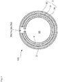
- the electrode assembly 3 has a linear slit 3S extending axially from a first axial end to a second axial end.
- the electrode assembly 3 has a double structure in which the two positive electrode plates 31 wound once and the two negative electrode plates 32 wound once are concentrically arranged with the separators 33 being interposed such that the slits 31a and 32a thereof are radially aligned.
- the slits 31a and 32a communicating one another configure the slit 3S of the electrode assembly 3.
- the linear slit 3S configured in this manner simplifies the structure including the positive electrode plates 31, the negative electrode plates 32, and the separators 33 each of which has a rectangular shape in a planar view and is wound once. Such a simplified structure leads to easier production and reduces defective winding misalignment.
- a positive electrode in the AA size is preferably 1.0 to 2.0 mm thick.
- a negative electrode in the AA size is preferably 0.3 to 0.8 mm thick.
- the positive electrode plates 31 and the negative electrode plates 32 are expanded and contracted around portions facing the slits 31a and 32a, thereby decreasing relative shift between the positive electrode plates 31 and the negative electrode plates 32 and reducing slippage.
- the electrode assembly can be expanded and contracted upon insertion into the battery case.
- the positive electrode plates 31 each have an expansion/contraction center (the portion facing the slit 31a) whereas the negative electrode plates 32 each have an expansion/contraction center (the portion facing the slit 32a) at a circumferential position different from that of the positive electrode plate 31.
- the positive electrode plate 31 and the negative electrode plate 32 adjacent to each other tend not to be relatively shifted, so that the electrode assembly 3 is less likely to be increased or decreased in outer diameter as compared to the structure shown in Fig. 2 .
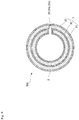
- an alkaline secondary battery 100 preferably includes a holder member 6 that is arranged in a hollow portion 3X of the electrode assembly 3 and is in contact with an inner circumferential surface 3m of the electrode assembly 3 so as to hold the electrode assembly 3 of which outer circumferential surface 3n is kept in contact with the inner circumferential surface 2m of the battery case 2.
- the holder member 6 is in contact with the inner circumferential surface 3m of the electrode assembly 3, more specifically, with the entire inner circumferential surface of the innermost positive electrode plate 31 in the present embodiment.
- the holder member 6 is configured by a single flat plate or layered flat plates made of elastic resin such as polypropylene or nylon, or made of metal.
- the holder member 6 configured by the flat plate is deformed by curving into a cylindrical shape and is arranged in the hollow portion 3X of the electrode assembly 3.
- the holder member 6 has elastic restoring force that causes an outer circumferential surface 6n of the holder member 6 to press the inner circumferential surface 3m of the electrode assembly 3 and also causes the outer circumferential surface 3n of the electrode assembly 3 to press the inner circumferential surface 2m of the battery case 2 (see the partial enlarged view in Fig. 2 ). More specifically, the holder member 6 presses and is in contact with the entire inner circumferential surface 3m of the electrode assembly 3.
- the holder member 6 thus preferably has a length not less than the inner circumferential length of the hollow portion 3X of the electrode assembly 3 and a width substantially equal to the axial length of the hollow portion 3X of the electrode assembly 3.
- the holder member 6 pressing the inner circumferential surface 3m of the electrode assembly 3 prevents separation of the positive active material of the innermost positive electrode plate 31 as well as separation of the negative active material of the negative electrode plate 32. This inhibits deterioration in current collection efficiency.
- the holder member 6 holds the electrode assembly 3 of which outer circumferential surface 3n is kept in contact with the inner circumferential surface 2m of the battery case 2, so that the outer circumferential surface 3n of the electrode assembly 3 is reliably in contact with the inner circumferential surface 2m of the battery case 2 and inhibits deterioration in charge-discharge efficiency.
- the holder member 6 configured by the single plate deformed into the cylindrical shape achieves a large space in the battery 100. This leads to increase in quantity of the electrolyte solution and prevention of increase in inner pressure of the battery.
- the two rectangular positive electrode plates 31 and two negative electrode plates 32 are alternately layered with the rectangular separators 33 being interposed.
- the layered product thus obtained is wound once to form the electrode assembly 3 in the cylindrical shape, and then it is arranged in the battery case 2.
- the electrode assembly 3 is reduced in diameter due to the slit 3S. It is thus possible to prevent troubles that the negative active material at the outer circumferential surface 3n of the electrode assembly 3 is brought into contact with the battery case 2 and is scraped, for example.
- the negative electrode plates 32 are each connected by welding or the like to the battery case 2 with a current collecting plate or the like being interposed.
- the electrolyte solution is then filled into the battery case 2.
- the holder member 6, which is deformed into a cylindrical shape so as to be smaller than the inner diameter of the hollow portion 3X of the electrode assembly 3, is arranged in the hollow portion 3X.
- the electrode assembly 3 can be thus fixed to the battery case 2.
- the lead pieces 311L of the positive electrode plates 31 are connected to the rear surface of the sealing member 5 directly or by way of a current collecting plate (not shown).
- the sealing member 5 is fixed by caulking or the like to the upper opening of the battery case 2 with the insulating member 4 being interposed.
- the electrolyte solution can be filled after the electrode assembly 3 is accommodated in the battery case 2 and the holder member 6 is arranged.
- the positive electrode plates 31, the negative electrode plates 32, and the separators 33 can be individually wound into a cylindrical shape and be accommodated into the battery case 2 one by one.
- plural sets e.g. each including one positive electrode plate 31, one separator 33, and one negative electrode plate 32
- the electrode assembly 3 has the slit 3S extending from the first axial end to the second axial end.
- the slit 3S eliminates a difference in height at the initially wound portion and suppresses distortion in the wound shape due to the initially wound portion and tears due to deterioration at an electrode portion overlapped with the initially wound portion.
- the electrode assembly 3 has the slit 3S extending from the first axial end to the second axial end, so that the slit 3S facilitates expansion and contraction in outer diameter of the electrode assembly 3.
- the expansion/contraction centers are located at substantially same positions.
- the positive electrode plates 31 and the negative electrode plates 32 are expanded and contracted around portions facing the slits 31a and 32a, thereby decreasing relative shift between the positive electrode plates 31 and the negative electrode plates 32 and reducing slippage as less as possible.
- the outer circumferential surface 3n of the electrode assembly 3 can be reliably made in contact with the inner circumferential surface 2m of the battery case 2, thereby inhibiting deterioration in charge-discharge efficiency.
- the present invention is not limited to the embodiment.
- the electrode assembly according to the embodiment having the double structure can alternatively have a single structure (see Fig. 4 ), or a triple or more structure.
- the electrode assembly 3 having the single structure has small strength so as to be most easily expanded and contracted in outer diameter thereof.
- the positive electrode plates 31 and the negative electrode plates 32 according to the embodiment are provided with the slits 31a and 32a that are radially aligned.
- the slits can be concentrically and alternately located so as to be aligned in a direction inclined from the radial direction and communicate one another.
- the slit 3S extends axially and linearly.
- the slit can extend linearly so as to be inclined from the axial direction, or can be curved or bent in a side view.
- the slits 31a of the positive electrode plates 31 and the slits 32a of the negative electrode plates 32 can have widths substantially equal to each other or different from each other.
- the holder member 6 can alternatively have an outer circumferential surface that is shaped so as to be fitted to the inner circumferential surface 3m of the electrode assembly 3 in the state where the outer circumferential surface 3n of the electrode assembly 3 is in contact with the inner circumferential surface 2m of the battery case 2. More specifically, as shown in Fig. 7 , the holder member 6 can be a resin or metal columnar body having a shape substantially same as that of the inner circumferential surface 3m of the electrode assembly 3 (having an outer diameter substantially same as the diameter of the inner circumferential surface 3m). The holder member 6 configured in this manner can be fitted to the hollow portion 3X of the electrode assembly 3 accommodated in the battery case 2, thereby achieving the effects similar to those of the embodiment described above.
- the holder member is arranged only in the hollow portion of the electrode assembly.
- the holder members each having a belt shape can be layered between the positive electrode plates or the negative electrode plates and the separators and the layered product can be wound once to form the cylindrical electrode assembly, so as to provide the holder members between the positive electrode plates or the negative electrode plates and the separators.
- This configuration further prevents separation of the active material and allows the outer circumferential surface of the electrode assembly to be more reliably made in contact with the inner circumferential surface of the battery case.
- the holder members need to be made of a porous material so as to provide paths for ions.
- the positive electrode and the negative electrode according to the embodiment are each produced by applying an active material to a punched steel plate.
- these electrodes can be each produced by filling an active material into a foamed substrate made of foamed nickel or the like.
- the current collector substrates configuring at least the positive electrode plates or the negative electrode plates can have elasticity so as to press the electrode assembly with the elasticity. In this configuration, the current collector substrates can press the electrode assembly with no use of any holder member. It is possible to prevent separation of the active material due to the loosened positive electrode plates or the negative electrode plates thereby to inhibit deterioration in current collection efficiency.
- the electrode assembly is provided at the outermost portion thereof with the negative electrode plate.
- the present invention is not limited to this configuration, and the electrode assembly can be provided at the outermost portion thereof with a positive electrode plate.
- each of the separators 33 can have a bag shape and be made of polyethylene or the like, so as to accommodate the positive electrode plate 31.
- the present invention is applicable not only to an alkaline secondary battery but also to a secondary battery such as a lithium ion secondary battery and a primary battery.
- a secondary battery according to a first example not part of the invention is a secondary battery according to a first example not part of the invention. It is noted that, in the first example, the members identical or corresponding to those of the embodiment are denoted by the same reference signs.
- a secondary battery 100 according to the first example is different from that of the embodiment in the positive electrode plates 31, the negative electrode plates 32, and the separators 33 which configure the electrode assembly 3.
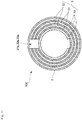
- the linear slits 31a, 32a, and 33a that axially extend from the axial first end to the second axial end of the cylinder, so that a section perpendicular to the axial direction has a C shape.
- the positive electrode plates 31 and the negative electrode plates 32 are arranged such that the slit 31a of the positive electrode plate 31 and the slit 32a of the negative electrode plate 32 adjacent to each other with each of the separators 33 being interposed are located at circumferentially different positions.
- the slits 31a of the positive electrode plates 31 and the slits 32a of the negative electrode plates 32 located at the different positions are not circumferentially overlapped with each other.
- the slits 31a of the plural (two in Fig. 10 ) positive electrode plates 31 are located as to orient in the same direction and the slits 32a of the plural (two in Fig. 10 ) negative electrode plates 32 are located as to orient in the same direction.
- the slits 31a of the positive electrode plates 31 and the slits 32a of the negative electrode plates 32 are located circumferentially opposite to each other, namely, at positions circumferentially different from each other at about 180 degrees.
- the slits 33a of the separators 33 are located as to orient in the same direction as the slits 31a of the positive electrode plates 31 or the slits 32a of the negative electrode plates 32 so as to communicate each other, in order to reliably insulate the positive electrode plates 31 and the negative electrode plates 32.
- the electrode assembly 3 according to the first example have a double structure in which the two positive electrode plates 31 wound once and the two negative electrode plates 32 wound once are concentrically located with the separators 33 being interposed such that the slits 31a of the positive electrode plates 31 and the slits 32a of the negative electrode plates 32 are located circumferentially opposite to each other.
- the slit 31a of the positive electrode plate 31 and the slit 32a of the negative electrode plate 32 which are located adjacent to each other with each of the separators 33 being interposed, are located at circumferentially different positions.
- the positive electrode plate 31 and the negative electrode plate 32 adjacent to each other are thus less likely to be relatively shifted.
- the positive electrode plates 31, the negative electrode plates 32, and the separators 33 are expanded and contracted around the portions facing the slits 31a, 32a, and 33a.
- the positive electrode plate 31 and the negative electrode plate 32 adjacent to each other tend to be relatively shifted and be loosened.
- the alkaline secondary battery 100 preferably includes a holder member 6 that is arranged in the hollow portion 3X of the electrode assembly 3 and is in contact with the inner circumferential surface 3m of the electrode assembly 3 so as to hold the electrode assembly 3 of which outer circumferential surface 3n is kept in contact with the inner circumferential surface 2m of the battery case 2.
- This holder member 6 is configured similarly to that of the embodiment.
- one rectangular negative electrode plate 32 is wound once into a cylindrical shape and is then accommodated in the battery case 2.
- one rectangular separator 33 is wound once into a cylindrical shape and is then accommodated inside the negative electrode plate 32 in the battery case 2.
- one rectangular positive electrode plate 31 is wound once into a cylindrical shape and is then accommodated inside the separator 33 in the battery case 2. In this manner, another negative electrode plate 32, another separator 33, and another positive electrode plate 31 are repetitively accommodated in this order.
- the plate is expanded so as to press and come into contact with the inner circumferential surface of the battery case 2 or the inner surface of the electrode plate 31 or 32 or the separator 33 that is already accommodated.
- the negative electrode plates 32 are each connected by welding or the like to the battery case 2 with a current collecting plate or the like being interposed.
- the electrolyte solution is then filled into the battery case 2.
- the electrode assembly 3 can be thus fixed to the battery case 2.
- the lead pieces 311L of the positive electrode plates 31 are connected to the rear surface of the sealing member 5 directly or by way of a current collecting plate (not shown).
- the sealing member 5 is fixed by caulking or the like to the upper opening of the battery case 2 with the insulating member 4 being interposed.
- Each of the negative electrode plates 32 can be connected to the current collecting plate every time the corresponding negative electrode plate 32 is accommodated in the battery case 2.
- the electrolyte solution can be filled after the electrode assembly 3 is accommodated in the battery case 2 and the holder member 6 is arranged.
- the slit 31a of the positive electrode plate 31 and the slit 32a of the negative electrode plate 32 adjacent to each other with each of the separators 33 being interposed are located at circumferentially different positions.
- the expansion/contraction center of the positive electrode plate 31 (a portion opposite to the slit 31a of the positive electrode plate 31 (the circumferential center)) and the expansion/contraction center of the negative electrode plate 32 (a portion opposite to the slit 32a of the negative electrode plate 32 (the circumferential center)) are located at circumferentially different positions.
- the positive electrode plate 31 and the negative electrode plate 32 adjacent to each other tend not to be relatively shifted.
- the positive electrode plate 31 and the negative electrode plates 32 are less likely to be loosened. It is thus possible to inhibit deterioration in charge-discharge efficiency of the secondary battery 100 or separation of the active material from the positive electrode plates 31 or the negative electrode plates 32 for a long period of time.
- all of the slits 31a of the positive electrode plates 31 and the slits 32a of the negative electrode plates 32 are located circumferentially opposite to each other.
- the slits are not necessarily located opposite to each other but can be located at arbitrary positions circumferentially different from each other, as shown in Fig. 3 according to the embodiment. In the case where the slits are located at arbitrary positions circumferentially different from each other, there is no need to locate the slits 31a of the positive electrode plates 31 and the slits 32a of the negative electrode plates 32 so as to be opposite to each other during the production of the battery 100, thereby reducing an assembly work load.
- the slit 31a of the positive electrode plate 31 and the slit 32a of the negative electrode plate 32 adjacent to each other with each of the separators 33 being interposed are located at the different positions.
- only the slit 31a of the positive electrode plate 31 and the slit 32a of the negative electrode plate 32 adjacent to each other with the innermost separator 33 in the electrode assembly 3 can be located at different positions.
- the slits 31a and 32a of the remaining positive and negative electrode plates 31 and 32 are preferably located as to orient in the same direction so as to communicate each other.
- the electrode plates 31 and 32 having the slits 31a and 32a located as to orient in the same direction can be easily expanded and contracted and thus made in contact with the inner circumferential surface of the battery case 2.
- the positive electrode plates 31 and the negative electrode plates 32 can be prevented from being loosened.
- a secondary battery according to the second example which is not part of the invention. It is noted that, in the second example, the members identical or corresponding to those of the embodiment or first example are denoted by the same reference signs.
- the configuration according to the second example can be combined with that of the embodiment or first example, or may not be combined with that of the embodiment or first example.
- a secondary battery 100 is a cylindrical battery of a low capacity type in which a AA battery has a capacity of not more than 1800 mAh or a AAA battery has a capacity of not more than 650 mAh, for example.
- the secondary battery 100 includes a metal battery case 2 in a bottomed cylindrical shape and a cylindrical electrode assembly 3 arranged in the battery case 2 and including a positive electrode plate 31, a negative electrode plate 32, and separators 33.
- the battery case 2 is coated with nickel plating and has a bottomed cylindrical shape. As shown in Fig. 12 , the battery case 2 has an upper opening that is sealed with a sealing member 5 with an insulating member 4 being interposed.
- the sealing member 5 has a rear surface at which a lead piece 311L projecting from the upper end of the positive electrode plate 31 is connected by welding or the like directly or by way of a current collecting plate (not shown), so that the sealing member 5 functions as a positive terminal.
- the battery case 2 has an inner circumferential surface 2m that is in contact with an outer circumferential surface 3n of the outermost negative electrode plate 32 in the electrode assembly 3 (see the partial enlarged view in Fig. 13 ).
- the electrode assembly 3 has a cylindrical shape and includes the positive electrode plate 31 and the negative electrode plate 32 that are concentrically and alternately arranged with the separators 33, which are nonwoven fabric made of polyolefin or the like, being interposed.
- Each of the separators includes an electrolyte solution of potassium hydroxide or the like impregnated therein.
- the positive electrode plate 31 includes a positive current collector substrate 311 of a metal plate provided with a large number of through holes 31h penetrating in the thickness direction, and a positive active material 312 that is filled in the through holes 31h in the positive current collector substrate 311 and is provided at a first surface 311a and a second surface 311b (hereinafter, also referred to as both surfaces) of the positive current collector substrate 311.
- the positive current collector substrate 311 has a generally rectangular shape in a planar view in a state where the positive electrode plate 31 is developed, and is provided at the upper end with a lead piece 311L.
- the positive current collector substrate 311 is a punched steel plate coated with nickel or the like and has the through holes 31h provided by punching a flat metal plate (such as a rolled sheet).
- the positive current collector substrate 311 is preferably made of steel because it can be pressed sufficiently.
- the positive current collector substrate 311 is preferably 10 ⁇ m or more and more preferably 20 ⁇ m or more in thickness.
- the positive current collector substrate 311 has the through holes 31h at an aperture ratio from 5 to 60%, for example.
- the function of holding the active material is deteriorated if the aperture ratio is lower than 5%, whereas the current collecting function is deteriorated if the aperture ratio exceeds 60%.
- Each of the through holes 31h is an opening in a circular shape, and has an opening diameter from 0.5 mm to 2.0 mm. It is difficult to form the through holes if the opening diameter is smaller than 0.5 mm, whereas the current collecting function may be deteriorated if the opening diameter exceeds 2.0 mm.
- the through holes 31h can have various opening shapes such as elliptic shapes, oval shapes, polygonal shapes including triangular shapes, rectangular shapes, and rhombic shapes.
- the opening diameter herein indicates a diameter of a circle, a short diameter of an ellipse, a shortest side of a triangle, a minimum diagonal of a polygon such as a rectangle or a rhombus.
- the positive active material 312 is provided substantially equally at the both surfaces of the positive current collector substrate 311, and can be nickel hydroxide in the case of a nickel-cadmium battery, and can be nickel hydroxide including calcium hydroxide added thereto in the case of a nickel-metal hydride battery.
- the positive active material 312 can be provided by applying to the positive current collector substrate 311 or by compression molding.
- the negative electrode plate 32 includes a negative current collector substrate of a punched steel plate coated with nickel plating similarly to the positive electrode plate 31 and a negative active material applied on the negative current collector substrate.
- the negative active material can be a mixture of a cadmium oxide powder and a metal cadmium powder in the case of a nickel-cadmium battery, and can be mainly a hydrogen storage alloy powder of the AB 5 type (the rare earth system), the AB 2 type (the Laves phase), or the like, in the case of a nickel-metal hydride battery.
- the positive electrode plates 31 and the negative electrode plates 32 are each configured by not a foamed substrate made of porous nickel or the like but a two-dimensional substrate such as a punched steel plate.
- the punched steel plate is more likely to have separation of an active material rather than a foamed substrate that has a three-dimensional structure.
- the punched steel plate is more elastic than a foamed substrate, thereby exerting a significant effect when the electrode assembly is expanded and contracted. Use of a plurality of punched steel plates exerts a more significant effect.
- a cover 34 that entirely covers the both surfaces of the positive electrode plate 31.
- This cover 34 is a metal plate provided with a large number of through holes 34h penetrating in the thickness direction, and is in contact with the positive active material 312 so as to sandwich the positive active material 312 between the positive current collector substrate 311 and the cover 34.
- the cover 34 includes a first cover portion 341 and a second cover portion 342.
- the first cover portion 341 is in contact with the positive active material 312 provided at the first surface 311a of the positive current collector substrate 311.
- the second cover portion 342 is in contact with the positive active material 312 provided at the second surface 311b of the positive current collector substrate 311.
- the positive electrode plate 31 is sandwiched between the first cover portion 341 and the second cover portion 342.
- the first cover portion 341 and the second cover portion 342 have substantially same shapes. As shown in Fig. 15(B) , each of the first cover portion 341 and the second cover portion 342 has a generally rectangular shape in a planar view in the state where the cover is developed, and has the shape substantially same as that of the positive current collector substrate 311 excluding the lead piece 311L. Each of the first cover portion 341 and the second cover portion 342 is a punched steel plate coated with nickel plating similarly to the positive current collector substrate 311, and is provided with the through holes 34h that are equal in shape to the through holes 31h in the positive current collector substrate 311 at the equal aperture ratio.
- first cover portion 341 and the second cover portion 342 are configured identically with the positive current collector substrate 311, thereby to reduce the production cost.
- the cover 34 sandwiching the positive electrode plate 31 can be alternatively plated with metal other than nickel.
- the cover 34 can be made of metal that is stable at the potential of the positive electrode plate 31, namely, nickel or metal other than nickel, or resin coated with nickel.
- the electrode assembly 3 according to the second example has linear slits 31a and 32a that axially extend from the axial first end to the second axial end of the cylinder, so that a section perpendicular to the axial direction has a C shape.
- the positive electrode plate 31 and the negative electrode plate 32 are concentrically and alternately arranged with the separators 33 being interposed such that the slit 31a of the positive electrode plate 31 and the slit 32a of the negative electrode plate 32 are located as to orient in the same direction and communicate each other.
- the cylindrical battery including the electrode assembly 3 configured as described above causes less relative shift between the positive electrode plate 31, the negative electrode plate 32, and the separators 33.
- the positive electrode plate 31 and the negative electrode plate 32 are expanded and contracted around portions facing the slits 31a and 32a, so that the electrode assembly 3 can be easily reduced in diameter upon insertion into the battery case 2 and the electrode assembly 3 can be easily pressed against the battery case 2 after the insertion.
- the slits 31a and 32a of the positive electrode plate 31 and the negative electrode plate 32 can be alternatively located at circumferentially different positions.
- the expansion/contraction center (the portion facing the slit 31a) of the positive electrode plate 31 and the expansion/contraction center (the portion facing the slit 32a) of the negative electrode plate 32 are located at circumferentially different positions.
- the positive electrode plate 31 and the negative electrode plate 32 adjacent to each other are less likely to be relatively shifted, and are less likely to be loosened after the insertion into the battery case 2.
- the first cover portion 341 and the second cover portion 342 are located at respective surfaces of one positive electrode plate 31, so that the single positive electrode plate 31 is sandwiched between the first cover portion 341 and the second cover portion 342.
- the structured product as described above and one negative electrode plate 32 are layered with the separators 33 being interposed.
- the layered product thus configured is wound once to form the electrode assembly 3 in the cylindrical shape, and then it is arranged in the battery case 2.
- the electrode assembly 3 is reduced in outer diameter due to the slit 31a of the positive electrode plate 31 and the slit 32a of the negative electrode plate 32.
- the negative active material at the outer circumferential surface 3n of the electrode assembly 3 is brought into contact with the battery case 2 and is scraped, for example.
- the negative electrode plate 32 is connected by welding or the like to the battery case 2 with the current collecting plate or the like being interposed.
- the electrolyte solution is then filled into the battery case 2.
- the lead piece 311L of the positive electrode plate 31 is connected to the rear surface of the sealing member 5 directly or by way of a current collecting plate (not shown).
- the sealing member 5 is fixed by caulking or the like to the upper opening of the battery case 2 with the insulating member 4 being interposed.
- the positive electrode plate 31, the negative electrode plate 32, and the separators 33 can be individually wound into a cylindrical shape and be accommodated into the battery case 2 one by one.
- a positive active material is applied to a punched steel plate as the positive current collector substrate and a cover is provided (positive current collector substrate: punched steel plate / cover: provided).
- the conventional sealed nickel-metal hydride batteries include a battery in which a foamed nickel porous body as the positive current collector substrate holds a positive active material and no cover is provided (positive current collector substrate: foamed nickel porous body / cover: not provided), a battery in which a foamed nickel porous body as the positive current collector substrate holds a positive active material and a cover is provided (positive current collector substrate: foamed nickel porous body / cover: provided), and a battery in which a positive active material is applied to a punched steel plate as the positive current collector substrate and no cover is provided (positive current collector substrate: punched steel plate / cover: not provided).
- Table 1 indicates results of the test. Negative electrodes, Positive electrodes, and the sealed nickel-metal hydride batteries used in the test were prepared in the following manner, and the test was performed under the following conditions.
- SBR styrene-butadiene rubber
- a positive active material was used in which nickel hydroxide containing 3% by mass of zinc and 0.6% by mass of cobalt in a solid solution was coated with 6% by mass of cobalt hydroxide, and was then oxidized with air at 110°C for one hour using a 18 M sodium hydroxide solution.
- An aqueous solution obtained by dissolving a thickener (carboxymethyl-cellulose) therein, an active material, and an aqueous PTFE (polytetrafluoroethylene) solution having a solid content of 0.3% by mass were mixed together to prepare a paste.
- the paste was filled in a nickel foamed substrate and dried.
- the nickel foamed substrate was then pressed into a predetermined thickness (0.97 mm) to obtain a positive electrode plate.
- a positive electrode plate was prepared in the same manner in (2-1) described above, and the positive electrode plate was sandwiched from both surfaces by a cover, namely, a punched steel plate of 35 ⁇ m thick (aperture ratio: 50% / hole diameter: 1 mm).
- a positive active material was used in which nickel hydroxide containing 3% by mass of zinc and 0.6% by mass of cobalt in a solid solution was coated with 6% by mass of cobalt hydroxide, and was then oxidized with air at 110°C for one hour using a 18 M sodium hydroxide solution.
- An aqueous solution obtained by dissolving a thickener (carboxymethyl cellulose) therein, an active material, an aqueous SBR solution having a solid content of 1% by mass, and an aqueous PTFE solution having a solid content of 0.5% by mass were mixed together to prepare a paste.
- the paste was applied to both surfaces of a punched steel plate of 35 ⁇ m thick (aperture ratio: 50% / hole diameter: 1 mm) and dried. The punched steel plate was then pressed against to have 0.96 mm in thickness so as to obtain a positive electrode plate.
- a positive electrode plate was prepared in the same manner in (2-3) described above, and the positive electrode plate was sandwiched from both surfaces by a cover, namely, a punched steel plate of 35 ⁇ m thick (aperture ratio: 50% / hole diameter: 1 mm).
- the positive electrode and the negative electrode were wound at 1 : 1.30 as the ratio of positive capacity to negative capacity, with separators being interposed, so as to form an electrode assembly, which was accommodated in a cylindrical battery case.
- the battery case was filled with 1.95 ml of an electrolyte solution including 7 M potassium hydroxide and 0.8 M lithium hydroxide, and sealed with a metal lid having a safety valve, so as to prepare a nickel-metal hydride rechargeable battery of the AA size having the capacity of 1000 mAh.
- the positive and negative electrodes were wound once.
- the batteries were charged for ten hours at 0.1 ItA (100 mA), were left for one hour, and were discharged at 0.2 ItA to 1.0 V at 20°C in one cycle.
- the batteries were then charged for 16 hours at 0.1 ItA (100 mA), were left for one hour, and were discharged at 0.2 ItA to 1.0 V repetitively in three charge-discharge cycles for formation.
- the battery including the punched steel plate as the positive current collector substrate and including no cover has discharge efficiency lower than that of the battery including the foamed nickel porous body.
- the batteries each including the foamed nickel porous body as the positive current collector substrate exert substantially equal discharge efficiency regardless of whether or not the cover is provided.
- the battery including the punched steel plate as the positive current collector substrate exerts significantly improved discharge efficiency by the provision of the cover.
- the battery including the foamed nickel porous body as the positive current collector substrate also exerts higher discharge efficiency at a high rate by the provision of the cover.
- the battery including the punched steel plate as the positive current collector substrate exerts higher discharge efficiency when being discharged at the low rate of 0.2 ItA as compared with a case of being discharged at the high rate of 1 ItA.
- the battery including the positive current collector substrate of the punched steel plate provided with the cover of a punched steel plate exerts discharge efficiency substantially equal to that of the battery including the foamed nickel porous body.
- the cover provided on a surface not facing the negative electrode plate can have a smaller aperture ratio.
- the positive electrode plate 31 which includes the positive current collector substrate 311 of the punched steel plate provided with the large number of through holes 31h and the positive active material 312 held by the positive current collector substrate 311, is sandwiched between the first cover portion 341 and the second cover portion 342. It is thus possible to prevent separation of the positive active material 312 from the positive current collector substrate 311, thereby improving current collection efficiency.
- the cover portions 341 and 342 are configured by the punched steel plates, so that a current collection path from the positive active material 312 apart from the positive current collector substrate 311 can be provided through the cover portions 341 and 342. This also leads to improvement in current collection efficiency.
- the positive current collector substrate 311 is configured by the punched steel plate provided with the large number of through holes 31h, and the cover portions 341 and 342 are also configured in similar manners. These configurations do not disturb shift of the electrolyte solution and ions.
- Each of the positive current collector substrate 311 and the cover portions 341 and 342, which is configured by the punched steel plate, can exert strength even with a small thickness.
- the elastic cover portions 341 and 342 can constantly press the positive active material 312 toward the positive current collector substrate 311 in accordance with expansion and contraction of the positive active material 312.
- the electrode assembly according to the second example is configured such that the positive electrode plate wound once and the negative electrode plate wound once are concentrically located with the separators being interposed.
- the positive electrode plate and the negative electrode plate can be wound spirally for a plurality of times.
- a plurality of positive electrode plates and a plurality of negative electrode plate can be concentrically and alternately located with the separators being interposed respectively.
- the cover is located at the both surfaces of the positive electrode plate.
- the cover can be alternatively provided at any one of the surfaces.
- an electrode assembly in which winding is performed for a plurality of times, tend to be loosened because the innermost portion of the electrode assembly does not receive pressure. It is thus preferred to provide the cover at the both surfaces or one of the surfaces of the innermost positive or negative electrode plate.
- the negative electrode plate can be also sandwiched by a cover.
- the cover sandwiching the negative electrode plate is preferably made of a material that is stable at the potential of the negative electrode plate, namely, copper, nickel, or iron coated with nickel.
- one cover portion is provided at each of the first and second surfaces of the positive electrode plate.
- the cover portion located at each of the first and second surfaces of the positive electrode plate can be circumferentially or axially divided into a plurality of cover pieces, for example.
- the positive current collector configured by the punched steel plate in the second example can be made of expanded metal.
- the expanded metal preferably has an aperture ratio from 5% to 60%. The function of holding the active material is deteriorated if the aperture ratio is lower than 5%, whereas the current collecting function is deteriorated if the aperture ratio exceeds 60%.
- the alkaline secondary battery 100 preferably includes a holder member 6 that is arranged in the hollow portion 3X of the electrode assembly 3 and is in contact with the inner circumferential surface of the electrode assembly 3 so as to hold the electrode assembly 3 of which outer circumferential surface 3n is kept in contact with the inner circumferential surface 2m of the battery case 2.
- This holder member 6 is configured similarly to that of the embodiment.
- the electrode assembly is provided at the outermost portion thereof with the negative electrode plate.
- the electrode assembly can be provided at the outermost portion thereof with a positive electrode plate.
- Each of the separators can have a bag shape and be made of polyethylene or the like, so as to accommodate the positive electrode plate 31.
- the battery according to the second example has the cylindrical shape.
- the battery can alternatively have a rectangular shape.
- the present invention is applicable not only to an alkaline secondary battery but also to a secondary battery such as a lithium ion secondary battery and a primary battery.
- the cylindrical electrode assembly can be prevented from distortion in a wound shape due to a difference in height at an initially wound portion and tears in an electrode.
Landscapes
- Chemical & Material Sciences (AREA)
- Chemical Kinetics & Catalysis (AREA)
- Electrochemistry (AREA)
- General Chemical & Material Sciences (AREA)
- Engineering & Computer Science (AREA)
- Materials Engineering (AREA)
- Manufacturing & Machinery (AREA)
- Secondary Cells (AREA)
- Cell Electrode Carriers And Collectors (AREA)
- Cell Separators (AREA)
Claims (5)
- Zylindrische Batterie (100), die ein zylindrisches Batteriegehäuse (2) und eine zylindrische Elektrodenanordnung (3), die in dem Batteriegehäuse (2) angeordnet ist, umfasst und eine positive Elektrodenplatte (31), eine negative Elektrodenplatte (32) und einen Abscheider (33) aufweist, wobei die positive Elektrodenplatte (31) und die negative Elektrodenplatte (32) konzentrisch sind und sich alternativ mit dem Abscheider, der dazwischen zwischengeordnet ist, befinden,
wobei die negative Elektrodenplatte (32) ein negatives Stromabnehmersubstrat einer gestanzten Stahlplatte und ein negatives aktives Material, das auf das negative Stromabnehmersubstrat aufgetragen ist, aufweist,
wobei das negative Stromabnehmersubstrat elastisch ist und gegen die Elektrodenanordnung drückt,
dadurch gekennzeichnet, dass
jede/r der positiven Elektrodenplatte (31), der negativen Elektrodenplatte (32) und des Abscheiders (33) einen Schlitz (31a, 32a, 33a) hat, der sich von einem ersten axialen Ende zu einem zweiten axialen Ende erstreckt, um eine C-Form in einem Querschnitt zu bilden, und
die Elektrodenanordnung (3) einen einzigen Schlitz (3S) hat, der sich durch den Schlitz (31a) der positiven Elektrodenplatte (31), den Schlitz (32a) der negativen Elektrodenplatte (32) und den Schlitz (33a) des Abscheiders (33) derart erstreckt, dass die Schlitze (31a, 32a, 33a) der positiven Elektrodenplatte (31), der negativen Elektrodenplatte (32) und des Abscheiders (33) miteinander kommunizieren, um Ausdehnungs-/Zusammenziehungsmitten an im Wesentlichen gleichen Positionen zu haben. - Zylindrische Batterie (100) nach Anspruch 1, wobei die äußerste Elektrodenplatte in der Elektrodenanordnung (3) mit dem Batteriegehäuse (2) in Kontakt ist.
- Zylindrische Batterie (100) nach Anspruch 1, die ferner ein Halteelement (6) umfasst, das in einem hohlen Abschnitt der Elektrodenanordnung (3) und optional zwischen der positiven Elektrodenplatte (31) und dem Abscheider (33) oder zwischen der negativen Elektrodenplatte (32) und dem Abscheider (33) zum Drücken gegen die Elektrodenanordnung (3) von innen, um die Elektrodenanordnung (3) zu halten, angeordnet ist.
- Zylindrische Batterie (100) nach Anspruch 1, wobei die positive Elektrodenplatte (31) ein Stromabnehmersubstrat und ein aktives Material, das auf dem Stromabnehmersubstrat aufgetragen ist, aufweist.
- Zylindrische Batterie (100) nach Anspruch 4, wobei das Stromabnehmersubstrat der positiven Elektrodenplatte (31) elastisch ist und gegen die Elektrodenanordnung drückt.
Applications Claiming Priority (5)
| Application Number | Priority Date | Filing Date | Title |
|---|---|---|---|
| JP2011067368 | 2011-03-25 | ||
| JP2011067363 | 2011-03-25 | ||
| JP2011104933 | 2011-05-10 | ||
| JP2011109074 | 2011-05-16 | ||
| PCT/JP2012/057616 WO2012133233A1 (ja) | 2011-03-25 | 2012-03-23 | 円筒形電池及び電池用電極構造 |
Publications (3)
| Publication Number | Publication Date |
|---|---|
| EP2690697A1 EP2690697A1 (de) | 2014-01-29 |
| EP2690697A4 EP2690697A4 (de) | 2014-08-20 |
| EP2690697B1 true EP2690697B1 (de) | 2018-05-09 |
Family
ID=46930955
Family Applications (1)
| Application Number | Title | Priority Date | Filing Date |
|---|---|---|---|
| EP12764292.4A Not-in-force EP2690697B1 (de) | 2011-03-25 | 2012-03-23 | Zylindrische batterie und elektrodenstruktur für die batterie |
Country Status (5)
| Country | Link |
|---|---|
| US (1) | US10243177B2 (de) |
| EP (1) | EP2690697B1 (de) |
| JP (1) | JP6020442B2 (de) |
| CN (1) | CN103443988B (de) |
| WO (1) | WO2012133233A1 (de) |
Families Citing this family (20)
| Publication number | Priority date | Publication date | Assignee | Title |
|---|---|---|---|---|
| WO2013012084A1 (ja) | 2011-07-20 | 2013-01-24 | 株式会社Gsユアサ | 円筒形電池 |
| US9722215B2 (en) | 2011-07-20 | 2017-08-01 | Gs Yuasa International Ltd. | Cylindrical battery |
| EP2741346B1 (de) | 2011-08-02 | 2019-04-17 | GS Yuasa International Ltd. | Elektrodenplatte, gestapelte elektrodenanordnung und batterien |
| EP2757624A4 (de) * | 2011-09-14 | 2015-04-22 | Gs Yuasa Int Ltd | Zylinderförmige batterie |
| EP2988362B1 (de) * | 2013-07-31 | 2020-04-01 | LG Chem, Ltd. | Gebogener elektrodenstapel und batteriepack damit |
| WO2015016463A1 (ko) * | 2013-07-31 | 2015-02-05 | 주식회사 엘지화학 | 휘어진 형상의 전극 적층체 및 이를 포함하는 전지셀 |
| US10263125B2 (en) * | 2014-05-16 | 2019-04-16 | Qorvo Us, Inc. | Varactor diode with heterostructure |
| JP6510573B2 (ja) * | 2017-02-10 | 2019-05-08 | 太陽誘電株式会社 | 蓄電素子 |
| GB201704292D0 (en) | 2017-03-17 | 2017-05-03 | Dyson Technology Ltd | Energy storage device |
| GB201704295D0 (en) | 2017-03-17 | 2017-05-03 | Dyson Technology Ltd | Energy storage device |
| GB201704294D0 (en) * | 2017-03-17 | 2017-05-03 | Dyson Technology Ltd | Energy storage device |
| GB201704293D0 (en) * | 2017-03-17 | 2017-05-03 | Dyson Technology Ltd | Energy storage device |
| US10153636B1 (en) * | 2017-05-26 | 2018-12-11 | Kitty Hawk Corporation | Electric vehicle hybrid battery system |
| JP7067019B2 (ja) * | 2017-10-30 | 2022-05-16 | セイコーエプソン株式会社 | 二次電池用電極、二次電池、電子機器、二次電池用電極の製造方法、二次電池の製造方法 |
| US20200358067A1 (en) * | 2019-05-06 | 2020-11-12 | Battelle Memorial Institute | Batteries and Battery Manufacture Methods |
| CN110323461B (zh) * | 2019-06-20 | 2024-08-27 | 武汉孚安特科技有限公司 | 一种高容量锂亚硫酰氯能量型电池及其制备方法 |
| CN119590627A (zh) * | 2019-10-09 | 2025-03-11 | 小鹰公司 | 用于不同飞行模式的混合功率系统 |
| KR102824436B1 (ko) * | 2021-03-04 | 2025-06-23 | 주식회사 엘지에너지솔루션 | 전극 조립체 및 이의 제조 방법 |
| EP4318725A4 (de) * | 2021-03-30 | 2025-07-09 | Panasonic Ip Man Co Ltd | Lithiumsekundärbatterie |
| US11655024B1 (en) | 2022-05-25 | 2023-05-23 | Kitty Hawk Corporation | Battery systems with power optimized energy source and energy storage optimized source |
Citations (1)
| Publication number | Priority date | Publication date | Assignee | Title |
|---|---|---|---|---|
| US4032695A (en) * | 1975-06-30 | 1977-06-28 | Saft-Societe Des Accumulateurs Fixes Et De Traction | Cylindrical electric cell |
Family Cites Families (39)
| Publication number | Priority date | Publication date | Assignee | Title |
|---|---|---|---|---|
| US3156585A (en) * | 1961-07-18 | 1964-11-10 | Sanyo Electric Co | Hermetically sealed storage batteries |
| JPS4723621U (de) | 1971-04-01 | 1972-11-16 | ||
| US4032696A (en) * | 1976-02-18 | 1977-06-28 | Union Carbide Corporation | Discrete anode bodies for use in various cylindrical cell systems |
| JPS5824967A (ja) | 1981-08-06 | 1983-02-15 | Towa Seisakusho:Kk | 平均化回路 |
| US4636526A (en) * | 1985-02-19 | 1987-01-13 | The Dow Chemical Company | Composites of unsintered calcium phosphates and synthetic biodegradable polymers useful as hard tissue prosthetics |
| JP2814655B2 (ja) * | 1990-02-22 | 1998-10-27 | 松下電器産業株式会社 | 渦巻電極を備えた電池 |
| JPH04229952A (ja) * | 1990-12-27 | 1992-08-19 | Shin Kobe Electric Mach Co Ltd | 円筒密閉形アルカリ蓄電池用渦巻き電極体 |
| JP3309463B2 (ja) | 1993-01-21 | 2002-07-29 | 松下電器産業株式会社 | 円筒形ニッケル・水素蓄電池 |
| JP3368632B2 (ja) | 1993-09-28 | 2003-01-20 | 上村工業株式会社 | 電池電極 |
| JPH07335209A (ja) | 1994-06-10 | 1995-12-22 | Matsushita Electric Ind Co Ltd | 電池用塗着式電極およびその製造方法 |
| JP3911724B2 (ja) | 1996-06-17 | 2007-05-09 | 日産自動車株式会社 | 電気自動車のバッテリ冷却風排出構造 |
| JP3439031B2 (ja) | 1996-07-01 | 2003-08-25 | 三洋電機株式会社 | インサイドアウト形電池 |
| JPH08339821A (ja) | 1996-07-30 | 1996-12-24 | Sanyo Electric Co Ltd | 金属−水素アルカリ蓄電池 |
| TW369734B (en) * | 1997-03-12 | 1999-09-11 | Sanyo Electric Co | Cubical battery |
| JP2000080406A (ja) | 1997-03-24 | 2000-03-21 | Katayama Tokushu Kogyo Kk | 電池用電極の製造方法および該方法で製造された電池用電極 |
| JP3004246B2 (ja) | 1997-03-24 | 2000-01-31 | 片山特殊工業株式会社 | 金属シートの製造方法、該方法により製造された金属シート、電池用電極の製造方法および該電池用電極 |
| JPH11176419A (ja) * | 1997-12-15 | 1999-07-02 | Tdk Corp | リチウム二次電池およびその製造方法 |
| JPH11185767A (ja) | 1997-12-17 | 1999-07-09 | Toshiba Battery Co Ltd | ニッケル水素二次電池及び電極の製造方法 |
| JPH11224689A (ja) | 1998-02-04 | 1999-08-17 | Fujitsu Ltd | 巻回式リチウム二次電池とその電極巻回体 |
| JPH11273708A (ja) * | 1998-03-24 | 1999-10-08 | Sony Corp | 巻回電極電池 |
| JPH11283612A (ja) | 1998-03-27 | 1999-10-15 | Ngk Insulators Ltd | リチウム二次電池 |
| JP3447285B2 (ja) * | 1998-07-10 | 2003-09-16 | 日立マクセル株式会社 | 非水二次電池 |
| JP2000315497A (ja) | 1999-04-30 | 2000-11-14 | Fuji Elelctrochem Co Ltd | インサイドアウト構造の円筒形電池 |
| WO2001020705A1 (en) * | 1999-09-16 | 2001-03-22 | Matsushita Electric Industrial Co., Ltd. | Sealed cylindrical nickel-hydrogen storage battery |
| JP2001223028A (ja) * | 2000-02-08 | 2001-08-17 | Shin Kobe Electric Mach Co Ltd | リチウムイオン電池 |
| JP2001236983A (ja) * | 2000-02-25 | 2001-08-31 | Sanoh Industrial Co Ltd | 電池用捲回電極 |
| JP2002260721A (ja) * | 2001-03-06 | 2002-09-13 | Toshiba Battery Co Ltd | ニッケル・水素二次電池 |
| JP2003257472A (ja) | 2002-02-28 | 2003-09-12 | Sanyo Electric Co Ltd | インサイドアウト型電池 |
| JP2003257471A (ja) * | 2002-02-28 | 2003-09-12 | Toyota Motor Corp | 蓄電素子およびその製造方法 |
| JP2004335380A (ja) * | 2003-05-09 | 2004-11-25 | Hitachi Maxell Ltd | 非水電解液電池 |
| CN100334769C (zh) * | 2004-05-28 | 2007-08-29 | 日本无公害电池研究所 | 二次电池 |
| JP5192710B2 (ja) * | 2006-06-30 | 2013-05-08 | 三井金属鉱業株式会社 | 非水電解液二次電池用負極 |
| JP2008159357A (ja) | 2006-12-22 | 2008-07-10 | Matsushita Electric Ind Co Ltd | 円筒形二次電池 |
| JP2010061820A (ja) * | 2008-09-01 | 2010-03-18 | Panasonic Corp | 非水系二次電池 |
| CN102197518A (zh) | 2009-08-07 | 2011-09-21 | 松下电器产业株式会社 | 非水电解质二次电池及其制造方法 |
| WO2013012084A1 (ja) | 2011-07-20 | 2013-01-24 | 株式会社Gsユアサ | 円筒形電池 |
| US9722215B2 (en) | 2011-07-20 | 2017-08-01 | Gs Yuasa International Ltd. | Cylindrical battery |
| EP2741346B1 (de) | 2011-08-02 | 2019-04-17 | GS Yuasa International Ltd. | Elektrodenplatte, gestapelte elektrodenanordnung und batterien |
| EP2757624A4 (de) * | 2011-09-14 | 2015-04-22 | Gs Yuasa Int Ltd | Zylinderförmige batterie |
-
2012
- 2012-03-23 EP EP12764292.4A patent/EP2690697B1/de not_active Not-in-force
- 2012-03-23 CN CN201280013978.0A patent/CN103443988B/zh not_active Expired - Fee Related
- 2012-03-23 US US14/006,867 patent/US10243177B2/en active Active
- 2012-03-23 JP JP2013507536A patent/JP6020442B2/ja active Active
- 2012-03-23 WO PCT/JP2012/057616 patent/WO2012133233A1/ja not_active Ceased
Patent Citations (1)
| Publication number | Priority date | Publication date | Assignee | Title |
|---|---|---|---|---|
| US4032695A (en) * | 1975-06-30 | 1977-06-28 | Saft-Societe Des Accumulateurs Fixes Et De Traction | Cylindrical electric cell |
Also Published As
| Publication number | Publication date |
|---|---|
| US10243177B2 (en) | 2019-03-26 |
| JPWO2012133233A1 (ja) | 2014-07-28 |
| EP2690697A1 (de) | 2014-01-29 |
| JP6020442B2 (ja) | 2016-11-02 |
| US20140011076A1 (en) | 2014-01-09 |
| CN103443988A (zh) | 2013-12-11 |
| WO2012133233A1 (ja) | 2012-10-04 |
| CN103443988B (zh) | 2017-03-22 |
| EP2690697A4 (de) | 2014-08-20 |
Similar Documents
| Publication | Publication Date | Title |
|---|---|---|
| EP2690697B1 (de) | Zylindrische batterie und elektrodenstruktur für die batterie | |
| US20140349158A1 (en) | Cylindrical battery | |
| US11502382B2 (en) | Nonaqueous electrolyte secondary battery | |
| US8815451B2 (en) | Negative-electrode plate and cylindrical cell including same | |
| EP3813178A1 (de) | Sekundärbatterie mit wasserfreiem elektrolyt | |
| US10468711B2 (en) | Electrode plate, layered electrode group, and battery | |
| JP2022152423A (ja) | 円筒形電池 | |
| EP3813177A1 (de) | Sekundärbatterie mit wasserfreiem elektrolyt | |
| EP2736098B1 (de) | Zylindrisch geformte batterie | |
| WO2019235259A1 (ja) | 非水電解質二次電池 | |
| US20250167306A1 (en) | Nonaqueous electrolyte secondary battery | |
| JPWO2020004135A1 (ja) | 非水電解質二次電池 | |
| WO2017090219A1 (ja) | 円筒形電池 | |
| JP2017183193A (ja) | ニッケル水素蓄電池 | |
| JP2006156186A (ja) | アルカリ二次電池用負極板およびその負極板を適用したアルカリ二次電池。 | |
| US20140170471A1 (en) | Electrode plate, layered electrode group, battery, and cylindrical battery | |
| EP4489211A1 (de) | Zylindrische sekundärbatterie mit nichtwässrigem elektrolyten | |
| EP4270613A1 (de) | Hermetisch verschlossene batterie | |
| CN118891769A (zh) | 非水电解质二次电池 | |
| JP3973115B2 (ja) | 巻回構造の電極体を有する電池 | |
| JP4017212B2 (ja) | 巻回構造の電極体を有するアルカリ二次電池 | |
| US20260051581A1 (en) | Energy storage element and method for producing an energy storage element | |
| EP4489174A1 (de) | Zylindrische sekundärbatterie mit nichtwässrigem elektrolyten | |
| JPWO2018173345A1 (ja) | ニッケル水素電池及びその製造方法 | |
| JPH09190836A5 (de) |
Legal Events
| Date | Code | Title | Description |
|---|---|---|---|
| PUAI | Public reference made under article 153(3) epc to a published international application that has entered the european phase |
Free format text: ORIGINAL CODE: 0009012 |
|
| 17P | Request for examination filed |
Effective date: 20130916 |
|
| AK | Designated contracting states |
Kind code of ref document: A1 Designated state(s): AL AT BE BG CH CY CZ DE DK EE ES FI FR GB GR HR HU IE IS IT LI LT LU LV MC MK MT NL NO PL PT RO RS SE SI SK SM TR |
|
| DAX | Request for extension of the european patent (deleted) | ||
| A4 | Supplementary search report drawn up and despatched |
Effective date: 20140723 |
|
| RIC1 | Information provided on ipc code assigned before grant |
Ipc: H01M 4/02 20060101ALN20140717BHEP Ipc: H01M 2/02 20060101ALN20140717BHEP Ipc: H01M 2/04 20060101ALI20140717BHEP Ipc: H01M 10/28 20060101ALI20140717BHEP Ipc: H01M 4/13 20100101ALI20140717BHEP Ipc: H01M 10/04 20060101AFI20140717BHEP Ipc: H01M 4/06 20060101ALI20140717BHEP Ipc: H01M 6/04 20060101ALI20140717BHEP Ipc: H01M 6/16 20060101ALI20140717BHEP Ipc: H01M 6/10 20060101ALI20140717BHEP Ipc: H01M 4/66 20060101ALI20140717BHEP Ipc: H01M 2/16 20060101ALI20140717BHEP Ipc: H01M 10/0525 20100101ALN20140717BHEP |
|
| 17Q | First examination report despatched |
Effective date: 20150708 |
|
| STAA | Information on the status of an ep patent application or granted ep patent |
Free format text: STATUS: EXAMINATION IS IN PROGRESS |
|
| REG | Reference to a national code |
Ref country code: DE Ref legal event code: R079 Ref document number: 602012046192 Country of ref document: DE Free format text: PREVIOUS MAIN CLASS: H01M0010040000 Ipc: H01M0002020000 |
|
| GRAP | Despatch of communication of intention to grant a patent |
Free format text: ORIGINAL CODE: EPIDOSNIGR1 |
|
| RIC1 | Information provided on ipc code assigned before grant |
Ipc: H01M 2/02 20060101AFI20171026BHEP Ipc: H01M 10/04 20060101ALN20171026BHEP Ipc: H01M 2/16 20060101ALI20171026BHEP Ipc: H01M 4/66 20060101ALI20171026BHEP Ipc: H01M 4/13 20100101ALI20171026BHEP |
|
| STAA | Information on the status of an ep patent application or granted ep patent |
Free format text: STATUS: GRANT OF PATENT IS INTENDED |
|
| RIC1 | Information provided on ipc code assigned before grant |
Ipc: H01M 10/04 20060101ALN20171115BHEP Ipc: H01M 2/16 20060101ALI20171115BHEP Ipc: H01M 4/13 20100101ALI20171115BHEP Ipc: H01M 2/02 20060101AFI20171115BHEP Ipc: H01M 4/66 20060101ALI20171115BHEP |
|
| INTG | Intention to grant announced |
Effective date: 20171130 |
|
| GRAS | Grant fee paid |
Free format text: ORIGINAL CODE: EPIDOSNIGR3 |
|
| GRAA | (expected) grant |
Free format text: ORIGINAL CODE: 0009210 |
|
| STAA | Information on the status of an ep patent application or granted ep patent |
Free format text: STATUS: THE PATENT HAS BEEN GRANTED |
|
| AK | Designated contracting states |
Kind code of ref document: B1 Designated state(s): AL AT BE BG CH CY CZ DE DK EE ES FI FR GB GR HR HU IE IS IT LI LT LU LV MC MK MT NL NO PL PT RO RS SE SI SK SM TR |
|
| REG | Reference to a national code |
Ref country code: GB Ref legal event code: FG4D |
|
| REG | Reference to a national code |
Ref country code: CH Ref legal event code: EP Ref country code: AT Ref legal event code: REF Ref document number: 998315 Country of ref document: AT Kind code of ref document: T Effective date: 20180515 |
|
| REG | Reference to a national code |
Ref country code: DE Ref legal event code: R096 Ref document number: 602012046192 Country of ref document: DE Ref country code: IE Ref legal event code: FG4D |
|
| REG | Reference to a national code |
Ref country code: NL Ref legal event code: MP Effective date: 20180509 |
|
| REG | Reference to a national code |
Ref country code: LT Ref legal event code: MG4D |
|
| PG25 | Lapsed in a contracting state [announced via postgrant information from national office to epo] |
Ref country code: FI Free format text: LAPSE BECAUSE OF FAILURE TO SUBMIT A TRANSLATION OF THE DESCRIPTION OR TO PAY THE FEE WITHIN THE PRESCRIBED TIME-LIMIT Effective date: 20180509 Ref country code: BG Free format text: LAPSE BECAUSE OF FAILURE TO SUBMIT A TRANSLATION OF THE DESCRIPTION OR TO PAY THE FEE WITHIN THE PRESCRIBED TIME-LIMIT Effective date: 20180809 Ref country code: LT Free format text: LAPSE BECAUSE OF FAILURE TO SUBMIT A TRANSLATION OF THE DESCRIPTION OR TO PAY THE FEE WITHIN THE PRESCRIBED TIME-LIMIT Effective date: 20180509 Ref country code: SE Free format text: LAPSE BECAUSE OF FAILURE TO SUBMIT A TRANSLATION OF THE DESCRIPTION OR TO PAY THE FEE WITHIN THE PRESCRIBED TIME-LIMIT Effective date: 20180509 Ref country code: NO Free format text: LAPSE BECAUSE OF FAILURE TO SUBMIT A TRANSLATION OF THE DESCRIPTION OR TO PAY THE FEE WITHIN THE PRESCRIBED TIME-LIMIT Effective date: 20180809 Ref country code: ES Free format text: LAPSE BECAUSE OF FAILURE TO SUBMIT A TRANSLATION OF THE DESCRIPTION OR TO PAY THE FEE WITHIN THE PRESCRIBED TIME-LIMIT Effective date: 20180509 |
|
| PG25 | Lapsed in a contracting state [announced via postgrant information from national office to epo] |
Ref country code: NL Free format text: LAPSE BECAUSE OF FAILURE TO SUBMIT A TRANSLATION OF THE DESCRIPTION OR TO PAY THE FEE WITHIN THE PRESCRIBED TIME-LIMIT Effective date: 20180509 Ref country code: LV Free format text: LAPSE BECAUSE OF FAILURE TO SUBMIT A TRANSLATION OF THE DESCRIPTION OR TO PAY THE FEE WITHIN THE PRESCRIBED TIME-LIMIT Effective date: 20180509 Ref country code: HR Free format text: LAPSE BECAUSE OF FAILURE TO SUBMIT A TRANSLATION OF THE DESCRIPTION OR TO PAY THE FEE WITHIN THE PRESCRIBED TIME-LIMIT Effective date: 20180509 Ref country code: GR Free format text: LAPSE BECAUSE OF FAILURE TO SUBMIT A TRANSLATION OF THE DESCRIPTION OR TO PAY THE FEE WITHIN THE PRESCRIBED TIME-LIMIT Effective date: 20180810 Ref country code: RS Free format text: LAPSE BECAUSE OF FAILURE TO SUBMIT A TRANSLATION OF THE DESCRIPTION OR TO PAY THE FEE WITHIN THE PRESCRIBED TIME-LIMIT Effective date: 20180509 |
|
| REG | Reference to a national code |
Ref country code: AT Ref legal event code: MK05 Ref document number: 998315 Country of ref document: AT Kind code of ref document: T Effective date: 20180509 |
|
| PG25 | Lapsed in a contracting state [announced via postgrant information from national office to epo] |
Ref country code: RO Free format text: LAPSE BECAUSE OF FAILURE TO SUBMIT A TRANSLATION OF THE DESCRIPTION OR TO PAY THE FEE WITHIN THE PRESCRIBED TIME-LIMIT Effective date: 20180509 Ref country code: SK Free format text: LAPSE BECAUSE OF FAILURE TO SUBMIT A TRANSLATION OF THE DESCRIPTION OR TO PAY THE FEE WITHIN THE PRESCRIBED TIME-LIMIT Effective date: 20180509 Ref country code: EE Free format text: LAPSE BECAUSE OF FAILURE TO SUBMIT A TRANSLATION OF THE DESCRIPTION OR TO PAY THE FEE WITHIN THE PRESCRIBED TIME-LIMIT Effective date: 20180509 Ref country code: CZ Free format text: LAPSE BECAUSE OF FAILURE TO SUBMIT A TRANSLATION OF THE DESCRIPTION OR TO PAY THE FEE WITHIN THE PRESCRIBED TIME-LIMIT Effective date: 20180509 Ref country code: DK Free format text: LAPSE BECAUSE OF FAILURE TO SUBMIT A TRANSLATION OF THE DESCRIPTION OR TO PAY THE FEE WITHIN THE PRESCRIBED TIME-LIMIT Effective date: 20180509 Ref country code: PL Free format text: LAPSE BECAUSE OF FAILURE TO SUBMIT A TRANSLATION OF THE DESCRIPTION OR TO PAY THE FEE WITHIN THE PRESCRIBED TIME-LIMIT Effective date: 20180509 Ref country code: AT Free format text: LAPSE BECAUSE OF FAILURE TO SUBMIT A TRANSLATION OF THE DESCRIPTION OR TO PAY THE FEE WITHIN THE PRESCRIBED TIME-LIMIT Effective date: 20180509 |
|
| REG | Reference to a national code |
Ref country code: DE Ref legal event code: R097 Ref document number: 602012046192 Country of ref document: DE |
|
| PG25 | Lapsed in a contracting state [announced via postgrant information from national office to epo] |
Ref country code: IT Free format text: LAPSE BECAUSE OF FAILURE TO SUBMIT A TRANSLATION OF THE DESCRIPTION OR TO PAY THE FEE WITHIN THE PRESCRIBED TIME-LIMIT Effective date: 20180509 Ref country code: SM Free format text: LAPSE BECAUSE OF FAILURE TO SUBMIT A TRANSLATION OF THE DESCRIPTION OR TO PAY THE FEE WITHIN THE PRESCRIBED TIME-LIMIT Effective date: 20180509 |
|
| PLBE | No opposition filed within time limit |
Free format text: ORIGINAL CODE: 0009261 |
|
| STAA | Information on the status of an ep patent application or granted ep patent |
Free format text: STATUS: NO OPPOSITION FILED WITHIN TIME LIMIT |
|
| 26N | No opposition filed |
Effective date: 20190212 |
|
| PG25 | Lapsed in a contracting state [announced via postgrant information from national office to epo] |
Ref country code: SI Free format text: LAPSE BECAUSE OF FAILURE TO SUBMIT A TRANSLATION OF THE DESCRIPTION OR TO PAY THE FEE WITHIN THE PRESCRIBED TIME-LIMIT Effective date: 20180509 |
|
| PG25 | Lapsed in a contracting state [announced via postgrant information from national office to epo] |
Ref country code: MC Free format text: LAPSE BECAUSE OF FAILURE TO SUBMIT A TRANSLATION OF THE DESCRIPTION OR TO PAY THE FEE WITHIN THE PRESCRIBED TIME-LIMIT Effective date: 20180509 |
|
| REG | Reference to a national code |
Ref country code: CH Ref legal event code: PL |
|
| GBPC | Gb: european patent ceased through non-payment of renewal fee |
Effective date: 20190323 |
|
| PG25 | Lapsed in a contracting state [announced via postgrant information from national office to epo] |
Ref country code: AL Free format text: LAPSE BECAUSE OF FAILURE TO SUBMIT A TRANSLATION OF THE DESCRIPTION OR TO PAY THE FEE WITHIN THE PRESCRIBED TIME-LIMIT Effective date: 20180509 Ref country code: LU Free format text: LAPSE BECAUSE OF NON-PAYMENT OF DUE FEES Effective date: 20190323 |
|
| REG | Reference to a national code |
Ref country code: BE Ref legal event code: MM Effective date: 20190331 |
|
| PG25 | Lapsed in a contracting state [announced via postgrant information from national office to epo] |
Ref country code: IE Free format text: LAPSE BECAUSE OF NON-PAYMENT OF DUE FEES Effective date: 20190323 Ref country code: CH Free format text: LAPSE BECAUSE OF NON-PAYMENT OF DUE FEES Effective date: 20190331 Ref country code: LI Free format text: LAPSE BECAUSE OF NON-PAYMENT OF DUE FEES Effective date: 20190331 Ref country code: GB Free format text: LAPSE BECAUSE OF NON-PAYMENT OF DUE FEES Effective date: 20190323 |
|
| PG25 | Lapsed in a contracting state [announced via postgrant information from national office to epo] |
Ref country code: FR Free format text: LAPSE BECAUSE OF NON-PAYMENT OF DUE FEES Effective date: 20190331 Ref country code: BE Free format text: LAPSE BECAUSE OF NON-PAYMENT OF DUE FEES Effective date: 20190331 |
|
| PG25 | Lapsed in a contracting state [announced via postgrant information from national office to epo] |
Ref country code: TR Free format text: LAPSE BECAUSE OF FAILURE TO SUBMIT A TRANSLATION OF THE DESCRIPTION OR TO PAY THE FEE WITHIN THE PRESCRIBED TIME-LIMIT Effective date: 20180509 |
|
| PG25 | Lapsed in a contracting state [announced via postgrant information from national office to epo] |
Ref country code: PT Free format text: LAPSE BECAUSE OF FAILURE TO SUBMIT A TRANSLATION OF THE DESCRIPTION OR TO PAY THE FEE WITHIN THE PRESCRIBED TIME-LIMIT Effective date: 20180910 Ref country code: MT Free format text: LAPSE BECAUSE OF NON-PAYMENT OF DUE FEES Effective date: 20190323 |
|
| REG | Reference to a national code |
Ref country code: DE Ref legal event code: R079 Ref document number: 602012046192 Country of ref document: DE Free format text: PREVIOUS MAIN CLASS: H01M0002020000 Ipc: H01M0050100000 |
|
| PG25 | Lapsed in a contracting state [announced via postgrant information from national office to epo] |
Ref country code: CY Free format text: LAPSE BECAUSE OF FAILURE TO SUBMIT A TRANSLATION OF THE DESCRIPTION OR TO PAY THE FEE WITHIN THE PRESCRIBED TIME-LIMIT Effective date: 20180509 |
|
| PG25 | Lapsed in a contracting state [announced via postgrant information from national office to epo] |
Ref country code: IS Free format text: LAPSE BECAUSE OF FAILURE TO SUBMIT A TRANSLATION OF THE DESCRIPTION OR TO PAY THE FEE WITHIN THE PRESCRIBED TIME-LIMIT Effective date: 20180909 |
|
| PG25 | Lapsed in a contracting state [announced via postgrant information from national office to epo] |
Ref country code: HU Free format text: LAPSE BECAUSE OF FAILURE TO SUBMIT A TRANSLATION OF THE DESCRIPTION OR TO PAY THE FEE WITHIN THE PRESCRIBED TIME-LIMIT; INVALID AB INITIO Effective date: 20120323 |
|
| PG25 | Lapsed in a contracting state [announced via postgrant information from national office to epo] |
Ref country code: MK Free format text: LAPSE BECAUSE OF FAILURE TO SUBMIT A TRANSLATION OF THE DESCRIPTION OR TO PAY THE FEE WITHIN THE PRESCRIBED TIME-LIMIT Effective date: 20180509 |
|
| P01 | Opt-out of the competence of the unified patent court (upc) registered |
Effective date: 20230522 |
|
| PGFP | Annual fee paid to national office [announced via postgrant information from national office to epo] |
Ref country code: DE Payment date: 20240130 Year of fee payment: 13 |
|
| REG | Reference to a national code |
Ref country code: DE Ref legal event code: R119 Ref document number: 602012046192 Country of ref document: DE |
|
| PG25 | Lapsed in a contracting state [announced via postgrant information from national office to epo] |
Ref country code: DE Free format text: LAPSE BECAUSE OF NON-PAYMENT OF DUE FEES Effective date: 20251001 |