EP2696251B1 - Procédé de surveillance de machines rotatives - Google Patents
Procédé de surveillance de machines rotatives Download PDFInfo
- Publication number
- EP2696251B1 EP2696251B1 EP13175459.0A EP13175459A EP2696251B1 EP 2696251 B1 EP2696251 B1 EP 2696251B1 EP 13175459 A EP13175459 A EP 13175459A EP 2696251 B1 EP2696251 B1 EP 2696251B1
- Authority
- EP
- European Patent Office
- Prior art keywords
- som
- diagnostic
- machine
- sensor data
- rules
- Prior art date
- Legal status (The legal status is an assumption and is not a legal conclusion. Google has not performed a legal analysis and makes no representation as to the accuracy of the status listed.)
- Active
Links
Images


Classifications
-
- G—PHYSICS
- G06—COMPUTING OR CALCULATING; COUNTING
- G06N—COMPUTING ARRANGEMENTS BASED ON SPECIFIC COMPUTATIONAL MODELS
- G06N5/00—Computing arrangements using knowledge-based models
- G06N5/04—Inference or reasoning models
- G06N5/046—Forward inferencing; Production systems
-
- G—PHYSICS
- G05—CONTROLLING; REGULATING
- G05B—CONTROL OR REGULATING SYSTEMS IN GENERAL; FUNCTIONAL ELEMENTS OF SUCH SYSTEMS; MONITORING OR TESTING ARRANGEMENTS FOR SUCH SYSTEMS OR ELEMENTS
- G05B23/00—Testing or monitoring of control systems or parts thereof
- G05B23/02—Electric testing or monitoring
- G05B23/0205—Electric testing or monitoring by means of a monitoring system capable of detecting and responding to faults
- G05B23/0208—Electric testing or monitoring by means of a monitoring system capable of detecting and responding to faults characterized by the configuration of the monitoring system
- G05B23/021—Electric testing or monitoring by means of a monitoring system capable of detecting and responding to faults characterized by the configuration of the monitoring system adopting a different treatment of each operating region or a different mode of the monitored system, e.g. transient modes; different operating configurations of monitored system
-
- G—PHYSICS
- G05—CONTROLLING; REGULATING
- G05B—CONTROL OR REGULATING SYSTEMS IN GENERAL; FUNCTIONAL ELEMENTS OF SUCH SYSTEMS; MONITORING OR TESTING ARRANGEMENTS FOR SUCH SYSTEMS OR ELEMENTS
- G05B23/00—Testing or monitoring of control systems or parts thereof
- G05B23/02—Electric testing or monitoring
- G05B23/0205—Electric testing or monitoring by means of a monitoring system capable of detecting and responding to faults
- G05B23/0218—Electric testing or monitoring by means of a monitoring system capable of detecting and responding to faults characterised by the fault detection method dealing with either existing or incipient faults
- G05B23/0243—Electric testing or monitoring by means of a monitoring system capable of detecting and responding to faults characterised by the fault detection method dealing with either existing or incipient faults model based detection method, e.g. first-principles knowledge model
- G05B23/0245—Electric testing or monitoring by means of a monitoring system capable of detecting and responding to faults characterised by the fault detection method dealing with either existing or incipient faults model based detection method, e.g. first-principles knowledge model based on a qualitative model, e.g. rule based; if-then decisions
-
- G—PHYSICS
- G06—COMPUTING OR CALCULATING; COUNTING
- G06N—COMPUTING ARRANGEMENTS BASED ON SPECIFIC COMPUTATIONAL MODELS
- G06N20/00—Machine learning
-
- G—PHYSICS
- G05—CONTROLLING; REGULATING
- G05B—CONTROL OR REGULATING SYSTEMS IN GENERAL; FUNCTIONAL ELEMENTS OF SUCH SYSTEMS; MONITORING OR TESTING ARRANGEMENTS FOR SUCH SYSTEMS OR ELEMENTS
- G05B2219/00—Program-control systems
- G05B2219/30—Nc systems
- G05B2219/33—Director till display
- G05B2219/33012—Kohonen network, single layer with neurodes, associated with codebook vector
Definitions
- the present invention relates to a method for monitoring rotating machinery, in particular wind turbines, which are provided with a plurality of sensors for detecting physical parameters.
- the vibration diagnostic condition monitoring has established.
- the oscillations of the individual components are permanently recorded as a state-describing variable.
- Online systems allow the permanently measured data to be sent to a service center. This provides the ability to monitor a wide variety of assets, regardless of their location. If the measured vibration quantities allow conclusions to be drawn about the damage to the component, the operator of the system will be informed. This can now, depending on the nature and severity of the damage, respond promptly.
- machine condition monitoring distinguishes between Level 1, Level 2, and Level 3, where Level 1 is the monitoring of measurements, e.g. Vibration readings, based on predetermined thresholds, Level 2 a diagnosis, typically by an expert in a monitoring center, to answer the question "What is the damage?" and Level 3 includes an issue and root cause analysis.
- Level 1 is the monitoring of measurements, e.g. Vibration readings, based on predetermined thresholds
- Level 2 a diagnosis, typically by an expert in a monitoring center, to answer the question "What is the damage?"
- Level 3 includes an issue and root cause analysis.
- FMEA error condition type and impact analysis
- the level 1 monitoring of machines is described by the formation of SOM by tracking the time course of the so-called quantization error of the formed SOM. Furthermore, it is also mentioned that SOMs can also be used in determining the type of error. Also in the US 2010/0114806 A1 describes the use of SOMs in machine monitoring.
- EP 2 472 440 A1 describes the use of SOMs in condition monitoring of production plants, proposing several different SOMs for different time bases and different space groups of the data provided by the sensors;
- the different space groups can, for example, relate to different parts of the system.
- a rotating machine e.g. a wind turbine
- the initialization of the monitoring process can be made particularly simple and efficient, if the plant code of the is identical or sufficiently similar to another, already monitored machine, the rule-based knowledge for the start model or the reference SOM are taken over.
- the knowledge-based deployment of the startup model can be accomplished, for example, using an FMEA method, using Markov graphs, using Petri nets, and / or using failure mode analysis via a Fault Tree Analysis (FTA) method.
- FFA Fault Tree Analysis
- an FMEA method is used.
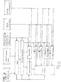
- a wind turbine which a rotor 10 with a hub 12 for three rotor blades (thereof are in Fig. 1 two rotor blades 14A, 14B shown).
- the rotor 10 is supported in a horizontal orientation in a nacelle 16 accommodating a generator 18 which is driven by the rotor shaft 20 for a transmission 22.
- the nacelle 16 is rotatably mounted about a vertical axis on a tower 24 and has a sensor 26 for measuring the wind speed and wind direction. Further, a sensor 28 for detecting the rotational speed of the rotor 10 is provided.
- the rotor blades 14A, 14B are each adjustable by means of a blade adjustment 32 about its longitudinal axis with respect to the hub 12 in order to realize a pitch adjustment of the rotor blades 14A, 14B in the usual way.
- a plurality of vibration sensors on the relevant system components is provided for the vibration-diagnostic condition monitoring of the wind turbine, for example a horizontally measuring vibration sensor 34 on the rotor main bearing 36, a horizontally measuring vibration sensor 38 on the A side of the generator 18 (also referred to as "DE" for the driving end
- the transmission 22 is typically provided with a plurality of vibration sensors, such as a horizontally-measuring sensor 42 for the planetary stage of the transmission, an axially measuring sensor 44 for the intermediate stage of the transmission 22, and a vertically measuring sensor 46 for the output stage of the transmission 22.
- the vibration sensors are accelerometers with a linear characteristic in high as well as in very low frequency ranges.
- the data acquired by the various sensors are collected in a data transfer device 48 and transmitted to a data processing unit 49 at or in the vicinity of the wind energy plant 10 and / or to a diagnosis point 50 remote from the wind power plant 10.
- the data processing unit 49 may also be connected upstream of a data transfer device 48 in order to ensure preprocessing of the data collected by the sensors, before they are transmitted to the diagnostic station 50.
- the diagnostic station typically comprises a data processing unit 52 for processing the received data and a display device 54 for displaying the processed data.
- the data transfer to the diagnostic station 50 is typically via the Internet. In particular, in areas with poor Internet connectivity, it is advantageous to perform as much data preprocessing before the data is transmitted to the diagnostic station 50.
- a plant operator operates a plurality of wind turbines, which may be of the same type or different, although type-identical systems may differ by the individual components used, such as type of generator and type of transmission.
- the plants usually differ in terms of their location or in terms of their location conditions: for example, for the operation of the plant, the relationship with the adjacent wind turbines, i. For example, whether a particular wind turbine is in the second row, the topography of the environment (e.g., placement on a hill or in a saddle), and fouling and development of the environment play a major role.
- a plant code for each wind turbine 10 specifying at least one of gearbox type, inverter type, rotor blade type, generator type and tower type, and the location of the plant in relation to the neighboring plants, topography of the environment, and vegetation and development of the environment.
- start sensor data are obtained in at least one basic operating state of the machine. It is limited to simple, easy-to-understand (typically quasi-stationary) operating states of the machine, which to a certain extent represent "normal states"; in Fig. 2 Such basic operating states in the diagram are denoted by A, B and C.
- a starting model for the machine is then set up with a set of rules for performing the monitoring, the set of rules determining which parameters in which way and with what weighting to be monitored and which sensor data should be obtained and used for this purpose.
- the rule set also specifies in what way and with which data the SOMs to be used in condition monitoring should be set up.
- the machine can be divided into several components, in the case of a wind turbine, for example.
- Tower, rotor main bearing, generator, inverter, gear, etc. and for each of the components can be determined at least one of the above priority numbers.
- the information already present with regard to the machine with regard to the occurrence of certain errors is to be included in condition monitoring in a rule-based manner in order to make the subsequent statistical data evaluation by means of SOMs particularly efficient.
- the operating states lying between the easily accessible and understood basic states A, B, C should also be made available to the error analysis in order to improve the overall understanding of the system.
- the start sensor data or the start model can be taken over with the rule set of this other system, the identity or similarity of the asset ratio ensures that the two systems are really comparable with each other sufficiently.
- a SOM allows the representation of data of any dimension in two- or three-dimensional maps, whereby the input space is defined by the data to be processed, for example a data set with m variables and with n measurements.
- the individual data vectors are assigned to a coordinate in the output field by means of vector distance calculations and neighborhood relationships, which can be interpreted as a map, the output coordinates being numbered consecutively.
- each coordinate is initially assigned a so-called weight vector whose dimension corresponds to the number m of variables of the input data record.
- BMU Best-Matching Unit
- the SOM generated in this case can be regarded as a "reference SOM" since it represents any normal state or reference state of the system.
- the degree of deviation of the current data vector, i. of the current system state, from the reference state can be estimated by the so-called quantization error, which represents the Euclidean distance between the current data vector and the weight vector of the BMU.
- a visualization and analysis of different states or "phases" within the data set, with which the SOM was trained, can be done by means of the representation of the so-called U-matrix ("Unified Distance Matrix”), where for each coordinate the Euclidean distances of its weight vector to those of its direct neighbor coordinates.
- U-matrix Unified Distance Matrix
- the information about the frequency of occurrence in relation to states of the U-matrix can be mapped by means of the so-called hits matrix, wherein for each coordinate it is shown how many data vectors from the data set it represents.
- sensor data are selected which are obtained in a reference operating phase of the machine and then used for the creation of a reference SOM on the basis of the rule set.
- a reference operating phase of the machine For example, it can be ensured in this way that only those sensor data which are relevant or critical for the machine to be monitored are evaluated at all.
- the data of the sensor 44 of the intermediate stage of the transmission 22 are not relevant, since this intermediate never undergoes any damage within the typical system life.
- the reference SOM typically uses the wind speed and, if appropriate, the wind direction, speed and power of the wind turbine, as well as various vibration characteristics measured at different locations.
- the SOMs are manually initialized (ie, the initial weight vectors are chosen) such that the same operating states of the machine at all SOMs are located in the same (coordinate) regions of the SOMs (eg, higher states) Speed / power (full load) always at the top right and states at standstill always at the bottom right). This considerably facilitates the evaluation of the SOMs.
- a Gaussian function is preferably selected.
- the sensor measurement data used for comparability may be necessary or convenient to interpolate the sensor measurement data used for comparability with other measurement data, e.g. to ensure the same time grid for all sensor measurement data.
- Different parameters / variables within the data set can be weighted differently in the SOM, so that a variable with a high weighting value will have a greater influence on the distance calculations, which will lower the error of these variables and, on the other hand, more strongly dominate the structure of the map becomes.
- the weighting of the individual parameters results from the start model.
- measurements that exceed a certain threshold relative to an average of a plurality of measurements are not considered in the SOMs, to falsify the SOMs by "amplitude outliers" in the measurement data, such as by careless technicians, bird strikes , Sensor errors or the like can be generated to avoid. For example, an average of the hundred highest amplitudes can be calculated, and then all measurement data whose value exceeds the value of "0.8 x average" can be removed from the data set.
- the reference SOM can be taken over in addition to the takeover of the start model.
- the reference SOM is, so to speak, the starting point for monitoring the operation of the machine with regard to the occurrence of errors and should therefore essentially represent the normal state or undisturbed operation of the machine ("good condition").
- the time profile of the quantization error is tracked by sensor data selected with reference to the rule set with respect to the reference SOM, i. the data vector corresponding to the current measured values is compared with the weight vector of the BMU, wherein the deviation, i. the quantization error, which is usually a good measure of the deviation of the current system state from the normal state.
- all parameters included in the reference SOM are tracked.
- the quantization error satisfies a criterion given by the rule set, that is, for example, exceeds a certain predetermined threshold, troubleshooting is started, since it is then assumed that there is such a large deviation of the current system state from the normal state that it is likely that an error ( eg excessive wear) of a component) (in this sense, the reference SOM acts as "Level 1 SOM").
- an alarm is also transmitted to the diagnostic station 50.
- At least a first "diagnosis SOM” (or “level 2 SOM", in the example of FIG Fig. 2 generated as a “diagnosis SOM 1" and “diagnosis SOM 2") with a subset of the sensor data obtained in the monitoring operation phase, which is then evaluated using the rule set to identify a cause of the error.
- the formation of subsets can take place with regard to the measurement times and / or the number of sensors, ie only part of the measurement times and / or part of the sensors are taken into account in the diagnostic SOM.
- the FMEA may show that a particular component of the machine is particularly critical in terms of susceptibility to errors, so that then mainly this component is analyzed in detail by means of a correspondingly set up diagnostic SOM.
- diagnostic SOM typically, corresponding subsets of the sensor data obtained in the reference operating phase will also be included in the diagnostic SOM in order to include corresponding "good status" information in the diagnostic SOM.
- the evaluation of the diagnostic SOM involves creating at least one 3D graph of the diagnostic SOM;
- one of the parameters taken into account in the diagnostic SOM eg oscillation amplitude measured by the rotor main bearing sensor
- the evaluation of the 3D graphs is typically carried out by a corresponding specialist in the diagnosis site, whereby a corresponding automatic image processing, for example with automatic pattern recognition, can be used as support.
- sensor data obtained during the reference operating phase of the machine can be set up for the evaluation of the fault diagnosis of the SOM and a 3D graph of the good state SOM for comparison with the 3D sensor.
- Diagram of the diagnostic SOM based on the rule set.
- a separate 3D graph can be created for the respective diagnostic SOM for at least two of the parameters contained in the diagnostic SOM, these parameters being selected on the basis of the rule set, ie one is typically the one according to FMEA especially look at the error-critical parameters in detail.
- diagnostic SOM when selecting the diagnostic SOM, i. in deciding which type of diagnostic SOM is first considered in detail, whose quantization errors are considered, i. For example, one first selects that diagnostic SOM whose quantization error (with respect to the current data vector) is particularly large, since a large quantization error is usually an indication of the presence of an error. For example, one can select such SOM as a diagnostic SOM whose quantization error is above a certain threshold.
- difference 3D representations can also be formed and evaluated, with, for example, a diagnostic SOM being subtracted from the corresponding good state SOM.
- the diagnostic SOMs For generating the diagnostic SOMs, at least part of the sensor data is preferably subdivided into at least two frequency bands based on the rule set (for example, the FMEA may show that certain errors of certain components in particular frequency bands are particularly well recognized).
- the diagnostic SOMs may differ with respect to the selected frequency band of the data of at least one of the sensors. Thus, it may be useful, for example, to set up a plurality of diagnostic SOMs for a particular vibration sensor, which differ with regard to the frequency band considered.
- At least one second diagnostic SOM in the example of FIG Fig. 2 as "diagnosis SOM 3" and “diagnosis SOM 4" with a different subset of the sensor data obtained in the monitoring operation phase created and evaluated to identify a cause of the error.
- the troubleshooting can be made particularly efficient: For example, it is based on the FMEA obtained evaluation rules first for the most common or most critical of its effect error by a particularly well representing this error first diagnostic SOM (or possibly several such first diagnostic SOMs).
- a starting model modified or improved in this way can then also be used for other wind energy plants that are sufficiently comparable with the present system, i. have an identical or sufficiently similar system characteristic number, be made available as a start model, wherein a reference SOM supplemented by sensor data obtained in the monitoring operation phase can also be made available as a reference SOM for other similar systems.
- the reference SOM may in particular also be expedient to modify the reference SOM with at least part of the sensor data obtained during the monitoring operating phase in order to adapt the reference SOM to changes in the state of the system; this is e.g. makes sense if a permanent alarm (in the form of a too large quantization error) due to the operational degradation of a component is to be avoided, i. the deteriorated system status is then defined as a new "good condition".
- a permanent alarm in the form of a too large quantization error
- the remote data transmission to the diagnostic station 50 is limited in some form, it is convenient to already locally create the SOMs in the data processing system 49 in or near the machine to be monitored, and then only those in the SOMs data transmitted by remote data transmission to the diagnostic station 50 in order to achieve a reduction of the transmitted data compared to the locally obtained sensor data.
- the collected sensor data be stored on-site to enable the retrospective creation of different on-site diagnostic SOMs.
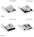
- FIG. 3 Examples of SOM diagrams are shown in 3D representation of the acceleration characteristic in the frequency band of 9 to 9.5 kHz of the vibration sensor on the generator B side of a wind turbine in good condition (left) or with a generator damage (right). It can be seen that the generator damage has a serious effect on this vibration characteristic in this frequency range.
- Fig. 4 are 3D representations of SOMs of the vibration characteristic at the rotor main bearing of a wind turbine at low-frequency evaluation (0.01 to 0.06 order) (left) or at higher-frequency evaluation (0.8 to 1.20 order) with tooth frequency of the planetary stage (right) shown. It can be seen that affect the main bearing most turbulence induced vibration shocks in the middle wind range, while the effects on the planetary gearing are relatively low.
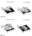
- Fig. 5 to 9 are shown 3D representations of SOMs of the vibration characteristic at the rotor main bearing of a wind turbine for different frequency ranges ( Fig. 5 : 10 Hz to 1 kHz; Fig. 6 : 0.01 to 0.06 order; Fig. 7 : 0.06 to 0.20 order; Fig. 8 : 0.08 to 1.20 order; and Fig. 9 : 1 , 80 to 2.20 order), with the good state being shown on the left and the state after the generator total damage on the right.
- the WEA is equipped with a system which allows to detect changes in wind speed and wind direction even before impact with the WEA (and the sensor mounted there), so that the WEA can proactively respond to such changes, for example by appropriate pitch Adjustment.
- the wind turbine can respond optimally to incoming gusts to optimize energy yield and minimize WEA component load (when the gust is already on the WAE, it is usually already too late for corrections).
- Such predictive sensing of the wind can be done, for example, by LIDAR (light detection and ranging) systems.
- the wind can be measured at a distance of 80 m from the installation, giving a reaction time of 4 seconds at a wind speed of 20 m / s. The effectiveness of such proactive control can then be monitored by the SOM analysis techniques described herein.
- the present invention combines the conventional rule-based analysis of the equipment states with a special statistical data evaluation by means of SOMs, which enables massive data reduction by the elimination of redundant information.
- the rule-based analysis by means of FMEA essentially has the function of focusing the "viewpoint" of the statistical evaluation on the correct object, whereby the efficiency and informative value of the statistical evaluation is greatly improved. Furthermore, by appropriately feeding the cognitive progress from the statistical analysis In rule-based analysis, rule-based analysis improves with increasing plant uptime.
- level 1 For level 1 analysis, a relatively global quantization error, which includes all or almost all measured parameters, is first used to detect the occurrence of an error.
- level 2 analysis the already existing rule-based knowledge is used to find the cause of the error by means of SOM evaluation in the most efficient and simple way possible. Although usually the help of a trained Level 2 specialist will still be required, this can facilitate the work by causing the same error to cause the same topological change in the SOM for different plants of the same type and therefore simply by looking at 3D Representations of the SOMs can be easily detected if the same error has already occurred in the present plant or in a plant of the same type.
- the data reduction associated with the statistical evaluation allows, for example, the realization of very fast measurement sequences, as a result of which, for example in the case of a wind energy plant, short-term turbulence-induced vibration excitations can also be detected and analyzed.
- the use of the upstream FMEA allows you to define the plant-specific and company-specific "correct" SOM diagrams during Level 2 analysis in order to work with the "correct” error-describing characteristics.
- the frequency band-oriented SOM analysis of a wind turbine it may be expedient, for example, to subdivide the signal of the vibration sensors into the four following frequency ranges: (1) 0 to 10 Hz: low-frequency oscillations of tower, nacelle and leaves, ie structural vibrations; (2) 10 Hz to 1 kHz: In this range, there are medium-frequency oscillations that result as a result of the system alignment yield; (3) 1 kHz to 30 kHz: High-frequency vibrations of gearboxes and bearings (caused by components such as bearing rings, rolling elements and gears) are present here; (4) 30 kHz to 200 kHz: Here are frequencies that can be used in the early detection of damage by means of shock pulse, SWAN (Stress Wave Analysis) or AE (Acoustic Emission); these are vibrations in the range of the transmitter resonance frequencies.
- SWAN Stress Wave Analysis
- AE Acoustic Emission
- the operating variables wind speed, generator power and speed are continuously measured in autarkic or integrated CMS with adjusted measuring rate as simultaneously as possible.
- the performance and speed characteristics of the individual wind turbines can be determined in two dimensions and compared with the nominal state. Comparing ten-minute averages, this corresponds to the static performance map of the WEA, comparing one-minute averages to the dynamic (e.g., turbulence-related) performance map and comparing one-second values, e.g. Evaluate game-influenced influences. Or one tends to evaluate the behavior of the wind turbine over weeks, months and years and monitors the process variables for changes.
- the sensor data is averaged in a temporal raster and with the time averaged values, a diagnostic SOM is created.
- the sensor data is averaged in several different temporal grids (eg one minute and ten minutes), wherein a separate diagnostic SOM is created for each grid, and wherein the thus-created diagnostic SOMs with a based on the corresponding non-averaged sensor data (the z .B., were obtained every second) diagnosed SOM are compared.
- Parameterization, resolution, scaling and display of the SOM diagrams are determined by means of the FMEA machine and application-related and left the same for comparable systems and phenomena. This then allows the comparison of similar machines and systems in a rather simple way or enables data reduction, checking the data quality and / or a simplified modeling.
- the phase boundaries in the U matrix can be identified and, in the case of transient states, calculate trajectories for the identification of the phenomena.
- SOM graphs can be generated daily, weekly, monthly, summed and / or analyzed for changes.
- SOM graphs can be used to read how efficiently a wind turbine was operated or whether there were longer standstills with wind by looking at wind speed graphs and graphs of wind turbine performance.
- the graphs oriented in the same direction make it possible to see at a glance where the wind was produced properly or where the wind was strong and the plant produced no power. If e.g. the appearance of the SOM graph of performance remains unchanged, but the wind speed signal looks unusual, it can be concluded that the wind sensor is gradually failing.
- system configuration errors, applets, cabling, possible swapping of power and wind speed sensor connections, etc. can be detected.
- the respective system characteristic can be read off (speed-proof, speed-variable, pitch-controlled, stall-controlled), or one can recognize peculiarities in the system control behavior. Similarly, it can be read from the SOM graphs in the pole-changing WEA, whether it is switched as intended or you can evaluate the number of hits, if necessary, is switched too often.
- VDI 3834 it is decided on the basis of evaluation vibration values v and a, which are determined from 20% load, on how good the running quality of the respective wind turbine is. If one uses SOM diagrams for "quality assessment", performance-related even the entire work area can be checked and evaluated "at a glance” with regard to the quality of the vibration. For this purpose, according to the invention, a "masking" or a masking window could be set in order to derive operation-dependent characteristic values. If deviations in the amplitudes of the graphs are determined, it is already possible to read from the basic characteristic of the graphs in which state there is potential for improvement with regard to vibrations, to effect resonances and / or to improve the "machine comfort".
- the vibration specialist can analyze and evaluate gears or other machine components "at a glance".
- Fig. 10 and 11 show filtered diagrams of order (left, 280-320 order) and frequency (right, 5.5-7.5 kHz) for two different inverter / generator combinations. Dominance in the order means that the generator dominates. Dominant Suggestions in frequency are an indicator that dominates the drive. In the right picture of Fig. 11 can even be read that only a narrow load range leads to more inverter conditional additional vibrations.
- Lattice mast towers are significantly softer than tubular towers, which can be due to the turbulence both axially and horizontally at high wind speeds and certain deviations in the mass imbalance and the blade angles in more low-frequency vibrations noticeable. For this purpose, it is necessary to use less averaged graphs to take into account the turbulence influences. This results in characteristics that can be seen "at a glance" on the tower side as well as on the rotor blade side in the SOM diagrams of the low-frequency oscillations. If additional natural frequencies are excited, there are further amplitude increases, which can only act locally. Stimulating in this low-frequency range, the Rotor rotational frequency and / or the Blattpassierfrequenz be. Characteristic of a lattice mast tower, for example, is that it better "damps" vibrations at partial load due to more flexibility.
- rotor blade types can be identified and classified.
- SOM rating also provides valuable information for rotor blade development and behavior in different winds, and also allows conclusions as to how turbulence impacts. It should also be noted that the rotor blades on lattice towers behave differently than on tubular towers.
- the oscillating sum characteristic values based on VDI 3834 and the vibration characteristic values around the rotational frequency of the generator can be represented.
- An alignment of two mutually coupled machine components is considered to be optimal, if at maximum load a low-vibration running behavior is present and the clutch compensates for deviations without forcing. It is common in the wind industry by the usually double elastic mounted driveline components that act at part load higher vibrations because of the associated alignment deviations. For analysis, it is possible to obtain rotational frequency and double-rotational frequency vibration graphs for the generator. to be created.
- FIG. 7-11 An example of a sudden total damage to a generator is in the Fig. 7-11 shown. Previously, the generator had been operated at high vibration for about 6 months. On the basis of SOM diagrams of the order-selective vibration velocities the development of the failure can be recognized. It is conspicuous in this example that probably only the low-frequency characteristics and the sum characteristic on the A-side were strongly influenced, but less the rotational frequency and double-rotational frequency components due to relaxation phenomena. It also shows an additional "hitting" with damage.
- alignment conditions, balancing states, machine states, gear and rolling bearing conditions can be evaluated and assessed at a glance via SOM diagrams during condition monitoring and diagnosis.
- Structural, system and turbulence influences can be distinguished by different measured value pretreatment and subsequent SOM evaluation.
- Individual disturbance events can be intercepted by a control query.
- the hits (number of events) and the amplitudes (for example in relation to VDI 3834) or set alarm and switch-off values are limited in order to avoid model distortions.
- phase boundaries of the U matrix can be assigned to typical states and the weight vectors can be adjusted based on nominal parameters.
- weighting factors are determined with regard to their dependencies or the underlying chain of action is taken into account.
- sudden or shock-like events can be masked out by means of filtering, Tayloring or other suitable algorithms.
- Drive and output speed characteristics can be compared in terms of plausibility SOM-based, and deviations can be used as a diagnostic criterion.
- Characteristic features can be monitored at different measuring points and compared to changes. This also reduces the fault tolerance or dependence on individual sensor errors.
- SOM charts can be compared with each other in terms of performance and machine-related, in order to conclude machine qualities or to compare the same machines or to configure them in the CMS.
- SOMs can be configured as user-dependent. Start-up or transient states are treated according to a sequential algorithm and stationary states after the batch algorithm.
- Pre-trained models can run in the embedded system, so that the amount of data can be significantly reduced.
- the specialist can configure which appearance he wants to evaluate with which parameter by means of SOM data analysis later or online. At the same time, it defines further analyzes depending on the signals.
- enveloping bodies and / or enveloping surfaces which describe warning and alarm conditions, can be formed, and after penetration, additional analyzes can be automatically activated.
- Amplitude SOM graphs and associated frequencies can be evaluated to estimate expected levels of damage and reduced lifespan. However, residual life can be estimated and residual usage forecasts derived.
- Turbulence effects and effects can be determined by comparisons of differently parameterized graphs.
- Selective vibration and diagnostic characteristics can be used in SOM diagrams for systematic machine analysis and can be automatically monitored based on diagnostic / vibration coding.
- State variables, control variables, controlled variables and operating variables can be used SOM-based in order to operate the plant in the optimum working range, and in the case of deviations from the ideal state, operating modes can be adapted.
- SOM charts can be used to avoid and / or hide inappropriate workspaces.
- Wind and stress profiles can be determined SOM-based and used to configure comparable plants / parks.
- the present invention can be used to actively intervene in the process state and operating state on the basis of multi-sensorially determined state information, so that the respective machine component can be used in its optimum operating range.
- optimal operating points and operating modes with the lowest possible operating behavior can be detected and used in the relevant system.
- Draglines are, for example, excavators used in the open pit with buckets with volumes in the order of 10m 3 , in which an advantageous vibration monitoring by means of the method according to the invention can be carried out.
- a resonance tracking can be realized.
- the full bucket excavator arm has different resonances than when the bucket is empty.
- the vibration behavior is also influenced eg also by the direction of travel.
- the excavator arm When driving with a full bucket to the truck, the excavator arm thus has a different resonance frequency than when driving with an empty bucket back; Since the direction of rotation is one of the standard parameters in excavator monitoring, the drive to the truck and the drive return to different trajectories, thus making it possible to detect various excavator boom resonances in the SOM.
- torque sensors are used for performance checks and for torsional vibration proofing. Alternatively, one tries to determine such information by means of coupling monitors, for example.
- Proactive condition monitoring based on SOM allows the marine propulsion system to be operated at its optimum operating point, and it can be recognized when learned driving habits are also announced due to changes in the machine's condition.
- Condition Monitoring with SOM can be used here e.g. indicate deterioration in the machine running behavior in time so that accidents can be avoided.
- Condition monitoring with SOM can also help to figure out if the behavior of the four or eight thrusters is really efficient with each other. Operating modes at the optimum operating point can both save energy costs and reduce additional vibrations and additional stresses
- Variable speed pumps run the risk of cavitation or inefficient running.
- the broadband vibrations resulting from cavitation are a criterion for the causal assignment in classical vibration diagnosis, they are not clearly assignable. Every pump has its own vibration patterns, depending on the medium and the version. It is then the task of the diagnostician to interpret the detected deviations and to interpret them with the experiences / results of comparisons. This is tedious, time-consuming and requires extensive knowledge. To make matters worse, that application-specific structure resonances and / or bearing damage in the same frequency range can also lead to additional interference. Cavitation also means changes in the process variables, such as more load fluctuations and pressure pulsations.
- Hydroelectric power plants have different operating states that can be operated with rule-based condition monitoring and rule-based control.
- An interpretation of the associated wave oscillations typically requires the specialist, who then adjusts the displayed changes in "minor work” with process conditions.
- proactive condition monitoring based on SOM the typical operating and vibration states can be taught in and then monitored for changes depending on the operating class.
Landscapes
- Engineering & Computer Science (AREA)
- General Physics & Mathematics (AREA)
- Physics & Mathematics (AREA)
- Theoretical Computer Science (AREA)
- Software Systems (AREA)
- Automation & Control Theory (AREA)
- Mathematical Physics (AREA)
- Evolutionary Computation (AREA)
- Data Mining & Analysis (AREA)
- Computing Systems (AREA)
- General Engineering & Computer Science (AREA)
- Artificial Intelligence (AREA)
- Medical Informatics (AREA)
- Computer Vision & Pattern Recognition (AREA)
- Computational Linguistics (AREA)
- Testing Of Devices, Machine Parts, Or Other Structures Thereof (AREA)
- Wind Motors (AREA)
- Testing And Monitoring For Control Systems (AREA)
Claims (29)
- Procédé de surveillance d'une machine rotative, qui est munie d'une multiplicité de capteurs pour détecter des paramètres physiques et qui fonctionne dans plusieurs états de fonctionnement variables, dans lequel la machine est une éolienne et dans lequel:on recueille des données de capteur de démarrage dans au moins un état de fonctionnement de base (A, B, C) de la machine;en se fondant sur les connaissances, on établit sur la base des données de capteur de démarrage un modèle de démarrage pour la machine avec un ensemble de règles pour l'exécution de la surveillance, qui détermine quels paramètres doivent être surveillés, de quelle manière et avec quelle pondération, et quelles données de capteur doivent à cet effet être recueillies et utilisées;on établit à l'aide de l'ensemble de règles une SOM de référence avec des données de capteur sélectionnées à l'aide de l'ensemble de règles, que l'on recueille dans une phase de fonctionnement de référence de la machine, dans lequel on désigne par SOM une Self-Organizing-Map [carte auto-adaptative];pendant une phase de fonctionnement de surveillance, on suit l'évolution temporelle de l'erreur de quantification des données de capteur sélectionnées à l'aide de l'ensemble de règles par rapport à la SOM de référence;on entame une recherche d'erreur, dans le cas où l'erreur de quantification remplit un critère prédéterminé par l'ensemble de règles,à l'aide de l'ensemble de règles, on dresse au moins une première SOM de diagnostic avec une quantité partielle des données de capteur recueillies dans la phase de fonctionnement de surveillance en ce qui concerne les instants de mesure et/ou le nombre des capteurs et en option avec des données de capteur recueillies dans la phase de fonctionnement de référence,on établit au moins un graphique 3D de la/des première(s) SOM de diagnostic et on l'évalue à l'aide de l'ensemble de règles, afin d'identifier une cause d'erreur;dans le cas où l'identification d'une cause d'erreur à partir de l'évaluation de la/des première(s) SOM de diagnostic n'est pas possible, on dresse au moins une deuxième SOM de diagnostic avec une autre quantité partielle des données de capteur recueillies dans la phase de fonctionnement de surveillance en ce qui concerne les instants de mesure et/ou le nombre des capteurs et en option avec des données de capteur recueillies dans la phase de fonctionnement de référence et on l'évalue, afin d'identifier une cause d'erreur;on vérifie le modèle de démarrage - et dès lors l'ensemble de règles - à l'aide d'évaluations des SOM de référence et/ou des SOM de diagnostic et on le modifie, dans la mesure où l'on recueille d'une part des données de capteur supplémentaires et d'autre part des connaissances supplémentaires sur le comportement de fonctionnement de la machine.
- Procédé selon la revendication 1, caractérisé en ce que pour l'évaluation de la/des SOM de diagnostic, on dresse une SOM d'état normal correspondant à la SOM de diagnostic respective avec des données de capteur recueillies pendant la phase de fonctionnement de référence de la machine et on établit à l'aide de l'ensemble de règles un graphique 3D de la SOM d'état normal, en vue de la comparaison avec le graphique 3D de la/des SOM de diagnostic.
- Procédé selon la revendication 2, caractérisé en ce que la comparaison de la/des SOM de diagnostic avec la SOM d'état normal est effectuée en utilisant un algorithme de traitement d'image.
- Procédé selon une revendication 2 ou 3, caractérisé en ce que pour l'évaluation des SOM de diagnostic on effectue une représentation 3D de la différence entre la SOM de diagnostic et une SOM d'état normal correspondante.
- Procédé selon l'une quelconque des revendications précédentes, caractérisé en ce que pour l'évaluation de la/des SOM de diagnostic on établit pour la SOM de diagnostic respective un graphique 3D particulier pour au moins deux des paramètres contenus dans la SOM de diagnostic respective, dans lequel ces paramètres sont sélectionnés à l'aide de l'ensemble de règles.
- Procédé selon l'une quelconque des revendications précédentes, caractérisé en ce que lors de la sélection de la/des SOM de diagnostic, on tient compte de leur erreur de quantification.
- Procédé selon la revendication 6, caractérisé en ce que l'on sélectionne comme SOM de diagnostic la/les SOM de diagnostic dont l'erreur de quantification se situe au-delà d'une valeur de seuil déterminée.
- Procédé selon l'une quelconque des revendications précédentes, caractérisé en ce que l'on divise au moins une partie des données de capteur en au moins deux bandes de fréquence à l'aide de l'ensemble de règles.
- Procédé selon la revendication 8, caractérisé en ce que les SOM de diagnostic diffèrent en ce qui concerne les bandes de fréquence des données d'au moins un des capteurs, choisies à l'aide de l'ensemble de règles.
- Procédé selon la revendication 9, caractérisé en ce que l'on suit ou on analyse dans au moins une SOM de diagnostic des trajectoires pour au moins un paramètre de la SOM de diagnostic.
- Procédé selon l'une quelconque des revendications précédentes, caractérisé en ce que l'on forme la moyenne pour au moins une partie des données de capteur dans une grille temporelle et on établit une SOM de diagnostic avec les valeurs moyennes temporelles.
- Procédé selon la revendication 11, caractérisé en ce que l'on forme la moyenne pour au moins une partie des données de capteur dans plusieurs grilles temporelles différentes et on établit une SOM de diagnostic séparée pour chaque grille.
- Procédé selon une des revendications 11 et 12, caractérisé en ce que l'on compare au moins la/les SOM de diagnostic établie (s) sur la base des données de capteur moyennes temporelles avec une SOM de diagnostic établie sur la base des données de capteurs correspondantes non moyennes.
- Procédé selon l'une quelconque des revendications précédentes, caractérisé en ce que l'on effectue en se fondant sur les connaissances l'établissement du modèle de démarrage avec utilisation d'un procédé AMDE, avec utilisation de graphes de Markov, avec utilisation de réseaux de Petri et/ou avec utilisation d'une analyse de type de défaillance au moyen d'une analyse de l'arbre de défaillances (procédé FTA).
- Procédé selon l'une quelconque des revendications précédentes, caractérisé en ce que l'on effectue en se fondant sur les connaissances l'établissement du modèle de démarrage avec utilisation d'un procédé AMDE et on utilise lors de l'établissement du modèle de démarrage au moins une des grandeurs suivantes:(1) un coefficient de priorité de diagnostic, qui résulte du produit des valeurs d'indice suivantes: gravité de l'effet de la survenance d'un défaut déterminé du point de vue de l'aptitude fonctionnelle de la machine; coûts résultants spécifiques à la machine à envisager lors de l'apparition du défaut; et possibilité de correction du défaut;(2) un coefficient de priorité d'oscillation, qui résulte du produit des valeurs d'indice suivantes: fréquence, avec laquelle une valeur limite d'oscillation prédéterminée est franchie vers le haut; gravité de l'effet du franchissement vers le haut de la valeur limite d'oscillation du point de vue de l'aptitude fonctionnelle de la machine; et probabilité de découverte du franchissement vers le haut de la valeur limite d'oscillation au moyen du système de détection d'oscillations prévu;(3) un coefficient de priorité de risque, qui résulte du produit des valeurs d'indice suivantes: fréquence, avec laquelle le défaut prédéterminé se produit dans le fonctionnement de la machine; gravité de l'effet de la survenance du défaut du point de vue de l'aptitude fonctionnelle de la machine; et probabilité de découverte de la survenance du défaut au moyen du schéma de diagnostic et du système de diagnostic utilisés.
- Procédé selon la revendication 15, caractérisé en ce que la machine est divisée en plusieurs composants et on détermine pour chacun des composants au moins un coefficient de priorité de diagnostic, au moins un coefficient de priorité d'oscillation et/ou au moins un coefficient de priorité de risque.
- Procédé selon l'une quelconque des revendications précédentes, caractérisé en ce que l'on modifie la SOM de référence avec au moins une partie des données de capteur recueillies pendant la phase de fonctionnement de surveillance, afin d'adapter la SOM de référence à des changements de l'état de la machine.
- Procédé selon l'une quelconque des revendications précédentes, caractérisé en ce que l'on initialise toutes les SOM de façon manuelle/déterministe, de telle manière que des états de fonctionnement identiques se disposent pour toutes les SOM dans des régions identiques des SOM.
- Procédé selon l'une quelconque des revendications précédentes, caractérisé en ce que l'on choisit la fonction de voisinage des SOM comme fonction de Gauss.
- Procédé selon l'une quelconque des revendications précédentes, caractérisé en ce que l'on interpole des données de mesure de capteur éventuellement dans un but de possibilité de comparaison avec d'autres données de mesure de capteur, afin de produire une grille temporelle identique pour toutes les données de mesure de capteur.
- Procédé selon l'une quelconque des revendications précédentes, caractérisé en ce que l'on ne tient pas compte dans les SOM de valeurs de mesure, qui dépassent une valeur limite déterminée, rapportée à une valeur moyenne de plusieurs valeurs de mesure.
- Procédé selon l'une quelconque des revendications précédentes, caractérisé en ce que l'on ne transmet que des données contenues dans les SOM au moyen d'une télétransmission de données à un centre de service situé loin de la machine, afin produire une réduction des données transmises par comparaison avec les données de capteur recueillies.
- Procédé selon l'une quelconque des revendications précédentes, caractérisé en ce que l'on envoie un signal d'alarme au centre de service, lorsque l'erreur de quantification de la SOM de référence remplit un critère prédéterminé par l'ensemble de règles.
- Procédé selon l'une quelconque des revendications précédentes, caractérisé en ce que les paramètres détectés contiennent la vitesse du vent, le nombre de tours et la puissance de l'éolienne, ainsi que des valeurs caractéristiques d'oscillation mesurées en différents points de l'éolienne.
- Procédé selon la revendication 24, caractérisé en ce que l'on sélectionne pour la/les SOM de diagnostic des valeurs caractéristiques d'oscillation déterminées de composants déterminés de la machine à l'aide de l'ensemble de règles.
- Procédé pour surveiller une multiplicité de machines rotatives, qui sont chacune munies d'une multiplicité de capteurs pour détecter des paramètres physiques et qui fonctionnent dans plusieurs états de fonctionnement variables, dans lequel les machines sont des éoliennes et dans lequel
les machines individuelles sont cataloguées par attribution d'un numéro caractéristique d'installation concernant la nature des composants et/ou l'emplacement de la machine respective;
avant de commencer la surveillance d'une machine sélectionnée, on recherche s'il se trouve parmi la multiplicité des machines une autre machine avec le même numéro caractéristique d'installation que la machine sélectionnée ou avec un numéro caractéristique d'installation ne s'écartant pas de plus d'une valeur prédéterminée du numéro caractéristique d'installation de la machine sélectionnée et, si c'est le cas, on reprend de l'autre machine un modèle de démarrage avec un ensemble de règles pour effectuer la surveillance, qui détermine quels paramètres doivent être surveillés, de quelle manière et avec quelle pondération, et quelles données de capteur doivent à cet effet être recueillies et utilisées, dans lequel le modèle de démarrage a été établi en se fondant sur les connaissances sur la base de données de capteur de démarrage, qui ont été recueillies dans au moins un état de fonctionnement de base quasi-stationnaire de l'autre machine, et(a) on établit à l'aide de l'ensemble de règles une SOM de référence avec des données de capteur sélectionnées à l'aide de l'ensemble de règles, qui ont été recueillies dans une phase de fonctionnement de référence de la machine sélectionnée, dans lequel on désigne par SOM une Self-Organizing-Map [carte auto-adaptative];
ou(b) on reprend une SOM de référence de l'autre machine, qui avait été établie à l'aide de l'ensemble de règles avec des données de capteur sélectionnées à l'aide de l'ensemble de règles de l'autre machine, qui sont recueillies dans une phase de fonctionnement de référence de l'autre machine;pendant une phase de fonctionnement de surveillance, on suit l'évolution temporelle de l'erreur de quantification des données de capteur de la machine sélectionnée, sélectionnées à l'aide de l'ensemble de règles, par rapport à la SOM de référence;
on entame une recherche d'erreur, dans le cas où l'erreur de quantification remplit un critère prédéterminé par l'ensemble de règles, dans laquelle
à l'aide de l'ensemble de règles, on dresse au moins une première SOM de diagnostic avec une quantité partielle des données de capteur recueillies dans la phase de fonctionnement de surveillance en ce qui concerne les instants de mesure et/ou le nombre des capteurs et en option avec des données de capteur recueillies dans la phase de fonctionnement de référence,
on établit au moins un graphique 3D de la/des première(s) SOM de diagnostic et on l'évalue, afin d'identifier une cause d'erreur;
dans le cas où aucune cause d'erreur claire ne ressort de l'évaluation de la/des première(s) SOM de diagnostic, on dresse au moins une deuxième SOM de diagnostic avec une autre quantité partielle des données de capteur recueillies dans la phase de fonctionnement de surveillance en ce qui concerne les instants de mesure et/ou le nombre des capteurs et en option avec des données de capteur recueillies dans la phase de fonctionnement de référence et on l'évalue, afin d'identifier une cause d'erreur;
on vérifie le modèle de démarrage - et dès lors l'ensemble de règles - à l'aide d'évaluations des SOM de référence et/ou des SOM de diagnostic et on le modifie, dans la mesure où l'on recueille d'une part des données de capteur supplémentaires et d'autre part des connaissances supplémentaires sur le comportement de fonctionnement de la machine;
on met à disposition comme SOM de référence, pour d'autres machines avec le même numéro caractéristique d'installation que la machine sélectionnée ou avec un numéro caractéristique d'installation ne s'écartant pas de plus d'une valeur prédéterminée du numéro caractéristique d'installation de la machine sélectionnée, le modèle de démarrage - éventuellement modifié - et/ou une SOM de référence complétée par des données de capteur recueillies dans la phase de fonctionnement de surveillance. - Procédé selon la revendication 26, caractérisé en ce que le numéro caractéristique d'installation spécifie au moins une des grandeurs suivantes: type de transmission, type de convertisseur, type de pale de rotor, type de générateur et type de tour.
- Procédé selon une revendication 26 ou 27, caractérisé en ce que le numéro caractéristique d'installation identifie l'emplacement du point de vue de la relation avec d'autres éoliennes, la topographie de l'environnement, et la végétation et les constructions dans l'environnement.
- Procédé selon l'une quelconque des revendications précédentes, caractérisé en ce que l'on effectue l'évaluation de la/des première(s) SOM de diagnostic et/ou de la/des deuxième(s) SOM de diagnostic automatiquement au moyen d'au moins un algorithme de traitement d'image.
Applications Claiming Priority (1)
| Application Number | Priority Date | Filing Date | Title |
|---|---|---|---|
| DE102012015485.2A DE102012015485A1 (de) | 2012-08-07 | 2012-08-07 | Verfahren zum Überwachen von rotierenden Maschinen |
Publications (3)
| Publication Number | Publication Date |
|---|---|
| EP2696251A2 EP2696251A2 (fr) | 2014-02-12 |
| EP2696251A3 EP2696251A3 (fr) | 2014-02-26 |
| EP2696251B1 true EP2696251B1 (fr) | 2019-12-04 |
Family
ID=48875498
Family Applications (1)
| Application Number | Title | Priority Date | Filing Date |
|---|---|---|---|
| EP13175459.0A Active EP2696251B1 (fr) | 2012-08-07 | 2013-07-08 | Procédé de surveillance de machines rotatives |
Country Status (4)
| Country | Link |
|---|---|
| US (1) | US9324037B2 (fr) |
| EP (1) | EP2696251B1 (fr) |
| DE (1) | DE102012015485A1 (fr) |
| ES (1) | ES2776651T3 (fr) |
Families Citing this family (47)
| Publication number | Priority date | Publication date | Assignee | Title |
|---|---|---|---|---|
| US9791352B2 (en) * | 2014-09-17 | 2017-10-17 | General Electric Company | Automated prognostics systems and methods |
| CN104390657B (zh) * | 2014-11-05 | 2017-12-12 | 浙江大学 | 一种发电机组运行参数测量传感器故障诊断方法及系统 |
| CN105890855B (zh) * | 2015-01-25 | 2019-03-15 | 雅砻江流域水电开发有限公司 | 一种水轮发电机内部故障诊断定位的方法 |
| DE102015207134A1 (de) | 2015-04-20 | 2016-10-20 | Prüftechnik Dieter Busch AG | Verfahren zum Erfassen von Vibrationen einer Vorrichtung und Vibrationserfassungssystem |
| US10823643B2 (en) * | 2015-11-06 | 2020-11-03 | Aktiebolaget Skf | Method and device for handling dynamic characteristics of a vibrating machine component |
| US12276420B2 (en) | 2016-02-03 | 2025-04-15 | Strong Force Iot Portfolio 2016, Llc | Industrial internet of things smart heating systems and methods that produce and use hydrogen fuel |
| CN106021796B (zh) * | 2016-06-03 | 2018-12-21 | 上海工具厂有限公司 | 一种铬钢叶片型面加工用球头铣刀的剩余寿命预测方法 |
| US10071820B2 (en) * | 2016-09-19 | 2018-09-11 | Pratt & Whitney Canada Corp. | Inclement weather detection for aircraft engines |
| US10860012B2 (en) | 2016-11-09 | 2020-12-08 | Yokogawa Engineering Asia Pte. Ltd | KPI calculation rule builder for advance plant monitoring and diagnostics |
| GB201621434D0 (en) * | 2016-12-16 | 2017-02-01 | Palantir Technologies Inc | Processing sensor logs |
| JP6785715B2 (ja) * | 2017-05-10 | 2020-11-18 | 株式会社日立製作所 | 正常異常判別装置、正常異常判別方法、及び正常異常判別システム |
| EP3525941B1 (fr) | 2017-07-06 | 2022-11-23 | Allgaier Werke GmbH | Dispositif et procédé de prise de vue de modèles de mouvement de tamiseurs oscillants |
| CN107861383B (zh) * | 2017-10-23 | 2021-07-09 | 天津大学 | 基于自适应观测器的卫星故障诊断与容错控制方法 |
| FR3073496B1 (fr) * | 2017-11-15 | 2020-11-20 | Sereema | Systeme et procede de diagnostic d'un desequilibre rotor d'une eolienne |
| JP6593429B2 (ja) * | 2017-12-20 | 2019-10-23 | ダイキン工業株式会社 | 流体装置 |
| KR102116064B1 (ko) * | 2018-01-29 | 2020-05-27 | (주)윈텍 | 설비 진단 시스템을 이용한 설비 진단 방법 |
| WO2019173702A1 (fr) * | 2018-03-08 | 2019-09-12 | Public Utility District No. 1 of Chelan County, WA | Système et procédé de modélisation de machine |
| WO2019207457A1 (fr) * | 2018-04-26 | 2019-10-31 | Abb Schweiz Ag | Procédé de surveillance et de commande de moteurs et système associé |
| JP7445928B2 (ja) * | 2018-05-07 | 2024-03-08 | ストロング フォース アイオーティ ポートフォリオ 2016,エルエルシー | 産業用のモノのインターネットを利用した解析及びメンテナンスのための機械信号のデータ収集、学習、ストリーミングのための方法並びにシステム |
| US20200133254A1 (en) | 2018-05-07 | 2020-04-30 | Strong Force Iot Portfolio 2016, Llc | Methods and systems for data collection, learning, and streaming of machine signals for part identification and operating characteristics determination using the industrial internet of things |
| EP3776116A1 (fr) * | 2018-05-18 | 2021-02-17 | Siemens Aktiengesellschaft | Localisation de défauts en ligne dans des processus industriels sans utiliser de modèle de système dynamique |
| CN109085771B (zh) * | 2018-08-24 | 2021-07-16 | 山推工程机械股份有限公司 | 一种铣刨机控制系统及控制方法 |
| CN109357647B (zh) * | 2018-09-29 | 2024-05-24 | 观为监测技术无锡股份有限公司 | 一种风电设备定位监测系统及方法 |
| EP3644037A1 (fr) * | 2018-10-26 | 2020-04-29 | Flender GmbH | Procédé de fonctionnement amélioré pour engrenage |
| CN109696906B (zh) * | 2018-12-27 | 2021-06-11 | 江苏科技大学 | 基于小波修正贝叶斯卷积能量的水下机器人推进器故障诊断方法 |
| BR112021012919A2 (pt) | 2018-12-31 | 2023-02-14 | Sentient Science Corp | Método e sistema para determinar um estado de dano de uma caixa de engrenagens de turbina eólica, e, mídia tangível, não transitória e legível por computador |
| EP4440165B1 (fr) | 2019-01-13 | 2026-02-18 | Strong Force Iot Portfolio 2016, LLC | Surveillance et gestion de réglages industriels |
| CN110687876B (zh) * | 2019-09-11 | 2021-02-12 | 北京科技大学 | 一种高温熔融金属作业典型事故预警方法及系统 |
| EP3885861A1 (fr) * | 2020-03-26 | 2021-09-29 | Siemens Aktiengesellschaft | Procédé et système de diagnostic de messages |
| CN111580506A (zh) * | 2020-06-03 | 2020-08-25 | 南京理工大学 | 基于信息融合的工业过程故障诊断方法 |
| KR102187063B1 (ko) * | 2020-07-13 | 2020-12-04 | 김인헌 | 서브 로터가 구비되는 드론 |
| TWI789641B (zh) * | 2020-10-23 | 2023-01-11 | 財團法人資訊工業策進會 | 用於評估振動設備的運作狀態的裝置及方法 |
| CN112882398B (zh) * | 2021-01-26 | 2022-10-21 | 四川华能宝兴河水电有限责任公司 | 一种水电站总控自动化仿真模拟系统 |
| AU2022214519A1 (en) | 2021-01-28 | 2023-08-10 | Odysight.Ai Ltd | Systems and methods for monitoring potential failure in a machine or a component thereof |
| EP4057093A1 (fr) * | 2021-03-12 | 2022-09-14 | ABB Schweiz AG | Surveillance de l'état de machines rotatives |
| CN113255848B (zh) * | 2021-07-08 | 2021-10-15 | 浙江大学 | 基于大数据学习的水轮机空化声信号辨识方法 |
| DE102021124254A1 (de) | 2021-09-20 | 2023-03-23 | Festo Se & Co. Kg | Maschinelles Lernverfahren zur Leckageerkennung in einem pneumatischen System |
| DE102021124253A1 (de) | 2021-09-20 | 2023-03-23 | Festo Se & Co. Kg | Maschinelles Lernverfahren zur Anomaliedetektion in einem elektrischen System |
| US11841758B1 (en) | 2022-02-14 | 2023-12-12 | GE Precision Healthcare LLC | Systems and methods for repairing a component of a device |
| US20250289586A1 (en) | 2022-04-27 | 2025-09-18 | Odysight.Ai Ltd | Monitoring a mechanism or a component thereof |
| WO2024028868A1 (fr) * | 2022-08-01 | 2024-02-08 | Odysight.Ai Ltd. | Surveillance d'un élément mobile |
| EP4325717A1 (fr) * | 2022-08-16 | 2024-02-21 | Wobben Properties GmbH | Procédé de commande d'un convertisseur |
| CN115453236B (zh) * | 2022-08-24 | 2024-11-22 | 大连海事大学 | 一种船舶风翼动力系统的故障诊断与健康评估方法 |
| US12028271B2 (en) | 2022-12-06 | 2024-07-02 | Bank Of America Corporation | Prioritizing messages for server processing based on monitoring and predicting server resource utilization |
| CN117970833B (zh) * | 2023-11-01 | 2025-04-11 | 安徽理工大学 | 用于扒渣机的智能化控制系统 |
| DE102024107918A1 (de) * | 2024-03-20 | 2025-03-27 | Schaeffler Technologies AG & Co. KG | System und Verfahren zur Vorhersage einer zu erwartenden Lebensdauer einer Maschine, KI-basiertes Vorhersagemodul sowie Verfahren zum Trainieren eines KI-basierten Vorhersagemodels |
| CN121277003B (zh) * | 2025-12-09 | 2026-02-17 | 中国建筑第六工程局有限公司 | 超大吨位钢塔竖转全过程监测与智能控制系统 |
Family Cites Families (12)
| Publication number | Priority date | Publication date | Assignee | Title |
|---|---|---|---|---|
| DE19649633A1 (de) | 1996-12-02 | 1998-06-04 | Abb Patent Gmbh | Verfahren zur Analyse und Darstellung von transienten Prozeßvorgängen |
| DE19734947B4 (de) | 1997-08-13 | 2010-04-29 | Otte, Ralf, Dr. | Verfahren zur Steuerung von Prozeßvorgängen |
| CA2405636C (fr) * | 2000-04-11 | 2011-08-23 | Recherche 2000 Inc. | Procede et appareil destines a l'acquisition, a la surveillance, a l'affichage et au diagnostic de parametres de fonctionnement d'electrolyseurs |
| JP4133627B2 (ja) | 2003-06-30 | 2008-08-13 | 新キャタピラー三菱株式会社 | 建設機械の状態判定装置及び建設機械の診断装置,並びに建設機械の状態判定方法及び建設機械の診断方法 |
| JP4032045B2 (ja) * | 2004-08-13 | 2008-01-16 | 新キャタピラー三菱株式会社 | データ処理方法及びデータ処理装置、並びに診断方法及び診断装置 |
| JP4356716B2 (ja) | 2006-08-03 | 2009-11-04 | パナソニック電工株式会社 | 異常監視装置 |
| DE102008006370A1 (de) | 2008-01-28 | 2009-07-30 | Prüftechnik Dieter Busch AG | Verfahren und Vorrichtung zum Überwachen einer Maschine |
| EP2085594B1 (fr) | 2008-01-29 | 2010-06-30 | Honda Motor Co., Ltd. | Système de contrôle pour moteur à combustion interne |
| WO2010011918A2 (fr) | 2008-07-24 | 2010-01-28 | University Of Cincinnati | Procédés de pronostic de systèmes mécaniques |
| US8332337B2 (en) | 2008-10-17 | 2012-12-11 | Lockheed Martin Corporation | Condition-based monitoring system for machinery and associated methods |
| WO2011143531A2 (fr) | 2010-05-13 | 2011-11-17 | University Of Cincinnati | Technique de pronostics d'éolienne à éolienne pour fermes éoliennes |
| EP2472440B1 (fr) | 2011-01-04 | 2014-06-25 | Siemens Aktiengesellschaft | Procédé et système pour le diagnostic du statut d'une installation |
-
2012
- 2012-08-07 DE DE102012015485.2A patent/DE102012015485A1/de not_active Withdrawn
-
2013
- 2013-07-08 EP EP13175459.0A patent/EP2696251B1/fr active Active
- 2013-07-08 ES ES13175459T patent/ES2776651T3/es active Active
- 2013-08-06 US US13/959,923 patent/US9324037B2/en not_active Expired - Fee Related
Non-Patent Citations (1)
| Title |
|---|
| EDZEL LAPIRA ET AL: "Wind turbine performance assessment using multi-regime modeling approach", RENEWABLE ENERGY, PERGAMON PRESS, OXFORD, GB, vol. 45, 7 February 2012 (2012-02-07), pages 86 - 95, XP028406906, ISSN: 0960-1481, [retrieved on 20120302], DOI: 10.1016/J.RENENE.2012.02.018 * |
Also Published As
| Publication number | Publication date |
|---|---|
| US20140046881A1 (en) | 2014-02-13 |
| EP2696251A3 (fr) | 2014-02-26 |
| ES2776651T3 (es) | 2020-07-31 |
| US9324037B2 (en) | 2016-04-26 |
| DE102012015485A1 (de) | 2014-05-15 |
| EP2696251A2 (fr) | 2014-02-12 |
Similar Documents
| Publication | Publication Date | Title |
|---|---|---|
| EP2696251B1 (fr) | Procédé de surveillance de machines rotatives | |
| DE102011052894B4 (de) | System zum Überwachen einer Windturbine | |
| DE102016105877B4 (de) | Verfahren und Vorrichtung zur Überwachung einer Maschine | |
| EP0895197B1 (fr) | Procédé pour surveiller des installations avec des composants mécaniques | |
| EP2021890B1 (fr) | Procede de surveillance des contraintes de pales de rotor d'eoliennes | |
| DE102010026678B4 (de) | Überwachungs-und Diagnosesystem für ein Fluidenergiemaschinensystem sowie Fluidenergiemachinensystem | |
| EP2169221B1 (fr) | Procédé de surveillance d'un engrenage d'éolienne | |
| EP1132614A2 (fr) | Système de réglage pour une éolienne | |
| EP2937560A1 (fr) | Dispositif de diagnostic d'éoliennes pour composants du générateur | |
| DE102011052666A1 (de) | Vorrichtung und Verfahren zum Betreiben einer Windkraftanlage | |
| DE102011117468A1 (de) | Verfahren, Recheneinheit und Einrichtung zur Überwachung eines Antriebstrangs | |
| EP4100803B1 (fr) | Procédé et dispositif de fonctionnement d'une machine avec un outil | |
| EP1892597A1 (fr) | Surveillance de machines et d'installations techniques | |
| EP4045791B1 (fr) | Procédé et appareil de surveillance mise en oeuvre par ordinateur pour une éolienne | |
| EP2706422A1 (fr) | Procédé de surveillance assistée par ordinateur du fonctionnement d'un système technique, en particulier d'une installation de production d'énergie électrique | |
| DE102015206515A1 (de) | Verfahren zum Bestimmen einer Restlebensdauer einer Windenergieanlage | |
| EP3833954B1 (fr) | Procédé de fonctionnement amélioré pour engrenage | |
| CH717054A2 (de) | Verfahren zur Diagnose eines Lagers. | |
| DE19707173C5 (de) | Maschinendiagnosesystem und Verfahren zur zustandsorientierten Betriebsüberwachung einer Maschine | |
| DE102022124435A1 (de) | Kavitationserkennungssystem | |
| DE112018001318T5 (de) | Windleistungserzeugungssystem | |
| DE102012024273A1 (de) | Verfahren zum Abstimmen belastungsabhängiger Prozesse bei Windenergieanlagen und Mittel zu dessen Implementierung | |
| DE102011075337A1 (de) | Verfahren und Vorrichtung zur Ansteuerung einer Anlage | |
| EP1189126A2 (fr) | Procédé de surveillance d'une installation | |
| CN112360702B (zh) | 一种振动数据的集中监测方法及装置 |
Legal Events
| Date | Code | Title | Description |
|---|---|---|---|
| PUAL | Search report despatched |
Free format text: ORIGINAL CODE: 0009013 |
|
| AK | Designated contracting states |
Kind code of ref document: A2 Designated state(s): AL AT BE BG CH CY CZ DE DK EE ES FI FR GB GR HR HU IE IS IT LI LT LU LV MC MK MT NL NO PL PT RO RS SE SI SK SM TR |
|
| AX | Request for extension of the european patent |
Extension state: BA ME |
|
| PUAI | Public reference made under article 153(3) epc to a published international application that has entered the european phase |
Free format text: ORIGINAL CODE: 0009012 |
|
| AK | Designated contracting states |
Kind code of ref document: A3 Designated state(s): AL AT BE BG CH CY CZ DE DK EE ES FI FR GB GR HR HU IE IS IT LI LT LU LV MC MK MT NL NO PL PT RO RS SE SI SK SM TR |
|
| AX | Request for extension of the european patent |
Extension state: BA ME |
|
| RIC1 | Information provided on ipc code assigned before grant |
Ipc: G05B 23/02 20060101AFI20140122BHEP |
|
| 17P | Request for examination filed |
Effective date: 20140313 |
|
| RBV | Designated contracting states (corrected) |
Designated state(s): AL AT BE BG CH CY CZ DE DK EE ES FI FR GB GR HR HU IE IS IT LI LT LU LV MC MK MT NL NO PL PT RO RS SE SI SK SM TR |
|
| 17Q | First examination report despatched |
Effective date: 20160708 |
|
| STAA | Information on the status of an ep patent application or granted ep patent |
Free format text: STATUS: EXAMINATION IS IN PROGRESS |
|
| GRAP | Despatch of communication of intention to grant a patent |
Free format text: ORIGINAL CODE: EPIDOSNIGR1 |
|
| STAA | Information on the status of an ep patent application or granted ep patent |
Free format text: STATUS: GRANT OF PATENT IS INTENDED |
|
| INTG | Intention to grant announced |
Effective date: 20190723 |
|
| RAP1 | Party data changed (applicant data changed or rights of an application transferred) |
Owner name: PRUEFTECHNIK DIETER BUSCH GMBH |
|
| GRAS | Grant fee paid |
Free format text: ORIGINAL CODE: EPIDOSNIGR3 |
|
| GRAA | (expected) grant |
Free format text: ORIGINAL CODE: 0009210 |
|
| STAA | Information on the status of an ep patent application or granted ep patent |
Free format text: STATUS: THE PATENT HAS BEEN GRANTED |
|
| AK | Designated contracting states |
Kind code of ref document: B1 Designated state(s): AL AT BE BG CH CY CZ DE DK EE ES FI FR GB GR HR HU IE IS IT LI LT LU LV MC MK MT NL NO PL PT RO RS SE SI SK SM TR |
|
| REG | Reference to a national code |
Ref country code: GB Ref legal event code: FG4D Free format text: NOT ENGLISH |
|
| REG | Reference to a national code |
Ref country code: CH Ref legal event code: EP |
|
| REG | Reference to a national code |
Ref country code: AT Ref legal event code: REF Ref document number: 1210159 Country of ref document: AT Kind code of ref document: T Effective date: 20191215 |
|
| REG | Reference to a national code |
Ref country code: DE Ref legal event code: R096 Ref document number: 502013014004 Country of ref document: DE |
|
| REG | Reference to a national code |
Ref country code: IE Ref legal event code: FG4D Free format text: LANGUAGE OF EP DOCUMENT: GERMAN |
|
| REG | Reference to a national code |
Ref country code: NL Ref legal event code: MP Effective date: 20191204 |
|
| REG | Reference to a national code |
Ref country code: LT Ref legal event code: MG4D |
|
| PG25 | Lapsed in a contracting state [announced via postgrant information from national office to epo] |
Ref country code: LT Free format text: LAPSE BECAUSE OF FAILURE TO SUBMIT A TRANSLATION OF THE DESCRIPTION OR TO PAY THE FEE WITHIN THE PRESCRIBED TIME-LIMIT Effective date: 20191204 Ref country code: NO Free format text: LAPSE BECAUSE OF FAILURE TO SUBMIT A TRANSLATION OF THE DESCRIPTION OR TO PAY THE FEE WITHIN THE PRESCRIBED TIME-LIMIT Effective date: 20200304 Ref country code: GR Free format text: LAPSE BECAUSE OF FAILURE TO SUBMIT A TRANSLATION OF THE DESCRIPTION OR TO PAY THE FEE WITHIN THE PRESCRIBED TIME-LIMIT Effective date: 20200305 Ref country code: BG Free format text: LAPSE BECAUSE OF FAILURE TO SUBMIT A TRANSLATION OF THE DESCRIPTION OR TO PAY THE FEE WITHIN THE PRESCRIBED TIME-LIMIT Effective date: 20200304 Ref country code: FI Free format text: LAPSE BECAUSE OF FAILURE TO SUBMIT A TRANSLATION OF THE DESCRIPTION OR TO PAY THE FEE WITHIN THE PRESCRIBED TIME-LIMIT Effective date: 20191204 Ref country code: LV Free format text: LAPSE BECAUSE OF FAILURE TO SUBMIT A TRANSLATION OF THE DESCRIPTION OR TO PAY THE FEE WITHIN THE PRESCRIBED TIME-LIMIT Effective date: 20191204 Ref country code: SE Free format text: LAPSE BECAUSE OF FAILURE TO SUBMIT A TRANSLATION OF THE DESCRIPTION OR TO PAY THE FEE WITHIN THE PRESCRIBED TIME-LIMIT Effective date: 20191204 |
|
| PG25 | Lapsed in a contracting state [announced via postgrant information from national office to epo] |
Ref country code: RS Free format text: LAPSE BECAUSE OF FAILURE TO SUBMIT A TRANSLATION OF THE DESCRIPTION OR TO PAY THE FEE WITHIN THE PRESCRIBED TIME-LIMIT Effective date: 20191204 Ref country code: HR Free format text: LAPSE BECAUSE OF FAILURE TO SUBMIT A TRANSLATION OF THE DESCRIPTION OR TO PAY THE FEE WITHIN THE PRESCRIBED TIME-LIMIT Effective date: 20191204 |
|
| PG25 | Lapsed in a contracting state [announced via postgrant information from national office to epo] |
Ref country code: AL Free format text: LAPSE BECAUSE OF FAILURE TO SUBMIT A TRANSLATION OF THE DESCRIPTION OR TO PAY THE FEE WITHIN THE PRESCRIBED TIME-LIMIT Effective date: 20191204 |
|
| PG25 | Lapsed in a contracting state [announced via postgrant information from national office to epo] |
Ref country code: PT Free format text: LAPSE BECAUSE OF FAILURE TO SUBMIT A TRANSLATION OF THE DESCRIPTION OR TO PAY THE FEE WITHIN THE PRESCRIBED TIME-LIMIT Effective date: 20200429 Ref country code: NL Free format text: LAPSE BECAUSE OF FAILURE TO SUBMIT A TRANSLATION OF THE DESCRIPTION OR TO PAY THE FEE WITHIN THE PRESCRIBED TIME-LIMIT Effective date: 20191204 Ref country code: RO Free format text: LAPSE BECAUSE OF FAILURE TO SUBMIT A TRANSLATION OF THE DESCRIPTION OR TO PAY THE FEE WITHIN THE PRESCRIBED TIME-LIMIT Effective date: 20191204 Ref country code: CZ Free format text: LAPSE BECAUSE OF FAILURE TO SUBMIT A TRANSLATION OF THE DESCRIPTION OR TO PAY THE FEE WITHIN THE PRESCRIBED TIME-LIMIT Effective date: 20191204 Ref country code: EE Free format text: LAPSE BECAUSE OF FAILURE TO SUBMIT A TRANSLATION OF THE DESCRIPTION OR TO PAY THE FEE WITHIN THE PRESCRIBED TIME-LIMIT Effective date: 20191204 |
|
| REG | Reference to a national code |
Ref country code: ES Ref legal event code: FG2A Ref document number: 2776651 Country of ref document: ES Kind code of ref document: T3 Effective date: 20200731 |
|
| PG25 | Lapsed in a contracting state [announced via postgrant information from national office to epo] |
Ref country code: SK Free format text: LAPSE BECAUSE OF FAILURE TO SUBMIT A TRANSLATION OF THE DESCRIPTION OR TO PAY THE FEE WITHIN THE PRESCRIBED TIME-LIMIT Effective date: 20191204 Ref country code: IS Free format text: LAPSE BECAUSE OF FAILURE TO SUBMIT A TRANSLATION OF THE DESCRIPTION OR TO PAY THE FEE WITHIN THE PRESCRIBED TIME-LIMIT Effective date: 20200404 Ref country code: SM Free format text: LAPSE BECAUSE OF FAILURE TO SUBMIT A TRANSLATION OF THE DESCRIPTION OR TO PAY THE FEE WITHIN THE PRESCRIBED TIME-LIMIT Effective date: 20191204 |
|
| REG | Reference to a national code |
Ref country code: DE Ref legal event code: R097 Ref document number: 502013014004 Country of ref document: DE |
|
| PLBE | No opposition filed within time limit |
Free format text: ORIGINAL CODE: 0009261 |
|
| STAA | Information on the status of an ep patent application or granted ep patent |
Free format text: STATUS: NO OPPOSITION FILED WITHIN TIME LIMIT |
|
| PG25 | Lapsed in a contracting state [announced via postgrant information from national office to epo] |
Ref country code: DK Free format text: LAPSE BECAUSE OF FAILURE TO SUBMIT A TRANSLATION OF THE DESCRIPTION OR TO PAY THE FEE WITHIN THE PRESCRIBED TIME-LIMIT Effective date: 20191204 |
|
| 26N | No opposition filed |
Effective date: 20200907 |
|
| PG25 | Lapsed in a contracting state [announced via postgrant information from national office to epo] |
Ref country code: PL Free format text: LAPSE BECAUSE OF FAILURE TO SUBMIT A TRANSLATION OF THE DESCRIPTION OR TO PAY THE FEE WITHIN THE PRESCRIBED TIME-LIMIT Effective date: 20191204 Ref country code: SI Free format text: LAPSE BECAUSE OF FAILURE TO SUBMIT A TRANSLATION OF THE DESCRIPTION OR TO PAY THE FEE WITHIN THE PRESCRIBED TIME-LIMIT Effective date: 20191204 |
|
| PG25 | Lapsed in a contracting state [announced via postgrant information from national office to epo] |
Ref country code: IT Free format text: LAPSE BECAUSE OF FAILURE TO SUBMIT A TRANSLATION OF THE DESCRIPTION OR TO PAY THE FEE WITHIN THE PRESCRIBED TIME-LIMIT Effective date: 20191204 |
|
| PG25 | Lapsed in a contracting state [announced via postgrant information from national office to epo] |
Ref country code: MC Free format text: LAPSE BECAUSE OF FAILURE TO SUBMIT A TRANSLATION OF THE DESCRIPTION OR TO PAY THE FEE WITHIN THE PRESCRIBED TIME-LIMIT Effective date: 20191204 |
|
| REG | Reference to a national code |
Ref country code: CH Ref legal event code: PL |
|
| REG | Reference to a national code |
Ref country code: BE Ref legal event code: MM Effective date: 20200731 |
|
| PG25 | Lapsed in a contracting state [announced via postgrant information from national office to epo] |
Ref country code: LU Free format text: LAPSE BECAUSE OF NON-PAYMENT OF DUE FEES Effective date: 20200708 Ref country code: LI Free format text: LAPSE BECAUSE OF NON-PAYMENT OF DUE FEES Effective date: 20200731 Ref country code: CH Free format text: LAPSE BECAUSE OF NON-PAYMENT OF DUE FEES Effective date: 20200731 |
|
| PG25 | Lapsed in a contracting state [announced via postgrant information from national office to epo] |
Ref country code: BE Free format text: LAPSE BECAUSE OF NON-PAYMENT OF DUE FEES Effective date: 20200731 |
|
| PG25 | Lapsed in a contracting state [announced via postgrant information from national office to epo] |
Ref country code: IE Free format text: LAPSE BECAUSE OF NON-PAYMENT OF DUE FEES Effective date: 20200708 |
|
| REG | Reference to a national code |
Ref country code: AT Ref legal event code: MM01 Ref document number: 1210159 Country of ref document: AT Kind code of ref document: T Effective date: 20200708 |
|
| PG25 | Lapsed in a contracting state [announced via postgrant information from national office to epo] |
Ref country code: AT Free format text: LAPSE BECAUSE OF NON-PAYMENT OF DUE FEES Effective date: 20200708 |
|
| PGFP | Annual fee paid to national office [announced via postgrant information from national office to epo] |
Ref country code: FR Payment date: 20210721 Year of fee payment: 9 |
|
| PGFP | Annual fee paid to national office [announced via postgrant information from national office to epo] |
Ref country code: ES Payment date: 20210819 Year of fee payment: 9 Ref country code: GB Payment date: 20210722 Year of fee payment: 9 Ref country code: DE Payment date: 20210721 Year of fee payment: 9 |
|
| PG25 | Lapsed in a contracting state [announced via postgrant information from national office to epo] |
Ref country code: TR Free format text: LAPSE BECAUSE OF FAILURE TO SUBMIT A TRANSLATION OF THE DESCRIPTION OR TO PAY THE FEE WITHIN THE PRESCRIBED TIME-LIMIT Effective date: 20191204 Ref country code: MT Free format text: LAPSE BECAUSE OF FAILURE TO SUBMIT A TRANSLATION OF THE DESCRIPTION OR TO PAY THE FEE WITHIN THE PRESCRIBED TIME-LIMIT Effective date: 20191204 Ref country code: CY Free format text: LAPSE BECAUSE OF FAILURE TO SUBMIT A TRANSLATION OF THE DESCRIPTION OR TO PAY THE FEE WITHIN THE PRESCRIBED TIME-LIMIT Effective date: 20191204 |
|
| PG25 | Lapsed in a contracting state [announced via postgrant information from national office to epo] |
Ref country code: MK Free format text: LAPSE BECAUSE OF FAILURE TO SUBMIT A TRANSLATION OF THE DESCRIPTION OR TO PAY THE FEE WITHIN THE PRESCRIBED TIME-LIMIT Effective date: 20191204 |
|
| REG | Reference to a national code |
Ref country code: DE Ref legal event code: R119 Ref document number: 502013014004 Country of ref document: DE |
|
| GBPC | Gb: european patent ceased through non-payment of renewal fee |
Effective date: 20220708 |
|
| PG25 | Lapsed in a contracting state [announced via postgrant information from national office to epo] |
Ref country code: FR Free format text: LAPSE BECAUSE OF NON-PAYMENT OF DUE FEES Effective date: 20220731 |
|
| PG25 | Lapsed in a contracting state [announced via postgrant information from national office to epo] |
Ref country code: GB Free format text: LAPSE BECAUSE OF NON-PAYMENT OF DUE FEES Effective date: 20220708 Ref country code: DE Free format text: LAPSE BECAUSE OF NON-PAYMENT OF DUE FEES Effective date: 20230201 |
|
| REG | Reference to a national code |
Ref country code: ES Ref legal event code: FD2A Effective date: 20230825 |
|
| PG25 | Lapsed in a contracting state [announced via postgrant information from national office to epo] |
Ref country code: ES Free format text: LAPSE BECAUSE OF NON-PAYMENT OF DUE FEES Effective date: 20220709 |