EP3833954B1 - Procédé de fonctionnement amélioré pour engrenage - Google Patents
Procédé de fonctionnement amélioré pour engrenage Download PDFInfo
- Publication number
- EP3833954B1 EP3833954B1 EP19778881.3A EP19778881A EP3833954B1 EP 3833954 B1 EP3833954 B1 EP 3833954B1 EP 19778881 A EP19778881 A EP 19778881A EP 3833954 B1 EP3833954 B1 EP 3833954B1
- Authority
- EP
- European Patent Office
- Prior art keywords
- transmission
- damage
- transmission component
- control unit
- operating method
- Prior art date
- Legal status (The legal status is an assumption and is not a legal conclusion. Google has not performed a legal analysis and makes no representation as to the accuracy of the status listed.)
- Active
Links
Images



Classifications
-
- G—PHYSICS
- G01—MEASURING; TESTING
- G01H—MEASUREMENT OF MECHANICAL VIBRATIONS OR ULTRASONIC, SONIC OR INFRASONIC WAVES
- G01H1/00—Measuring characteristics of vibrations in solids by using direct conduction to the detector
- G01H1/003—Measuring characteristics of vibrations in solids by using direct conduction to the detector of rotating machines
-
- G—PHYSICS
- G01—MEASURING; TESTING
- G01M—TESTING STATIC OR DYNAMIC BALANCE OF MACHINES OR STRUCTURES; TESTING OF STRUCTURES OR APPARATUS, NOT OTHERWISE PROVIDED FOR
- G01M13/00—Testing of machine parts
- G01M13/02—Gearings; Transmission mechanisms
-
- G—PHYSICS
- G01—MEASURING; TESTING
- G01M—TESTING STATIC OR DYNAMIC BALANCE OF MACHINES OR STRUCTURES; TESTING OF STRUCTURES OR APPARATUS, NOT OTHERWISE PROVIDED FOR
- G01M13/00—Testing of machine parts
-
- G—PHYSICS
- G06—COMPUTING OR CALCULATING; COUNTING
- G06Q—INFORMATION AND COMMUNICATION TECHNOLOGY [ICT] SPECIALLY ADAPTED FOR ADMINISTRATIVE, COMMERCIAL, FINANCIAL, MANAGERIAL OR SUPERVISORY PURPOSES; SYSTEMS OR METHODS SPECIALLY ADAPTED FOR ADMINISTRATIVE, COMMERCIAL, FINANCIAL, MANAGERIAL OR SUPERVISORY PURPOSES, NOT OTHERWISE PROVIDED FOR
- G06Q10/00—Administration; Management
- G06Q10/08—Logistics, e.g. warehousing, loading or distribution; Inventory or stock management
- G06Q10/087—Inventory or stock management, e.g. order filling, procurement or balancing against orders
-
- G—PHYSICS
- G06—COMPUTING OR CALCULATING; COUNTING
- G06Q—INFORMATION AND COMMUNICATION TECHNOLOGY [ICT] SPECIALLY ADAPTED FOR ADMINISTRATIVE, COMMERCIAL, FINANCIAL, MANAGERIAL OR SUPERVISORY PURPOSES; SYSTEMS OR METHODS SPECIALLY ADAPTED FOR ADMINISTRATIVE, COMMERCIAL, FINANCIAL, MANAGERIAL OR SUPERVISORY PURPOSES, NOT OTHERWISE PROVIDED FOR
- G06Q10/00—Administration; Management
- G06Q10/20—Administration of product repair or maintenance
Definitions
- the invention relates to an operating method for a transmission, with which a probable failure time for a transmission component can be predicted.
- the invention also relates to a computer program product with which the claimed operating method can be implemented.
- the invention relates to a control unit for a transmission, which is equipped with a corresponding computer program product.
- the invention also relates to a monitoring system having such a control unit.
- the invention relates to a transmission that can be coupled to such a monitoring system and to a transmission application equipped with a corresponding transmission.
- a wind turbine gearbox is known that is equipped with a plurality of acceleration sensors and speed sensors. These generate measurement data that map the vibration state and speed of at least one shaft.
- the acceleration sensors and speed sensors are connected to a control unit, which is evaluated by a computer program. Based on this data, the computer program determines the existing damage status of the gearbox.
- a known operating method for transmissions involves determining damage accumulation for rotating components of the transmission. Furthermore, a load spectrum is determined. A component to be analyzed is divided into several sections, and individual load spectrums are determined accordingly.
- EP 2 264 314 A2 discloses an operating method for a wind turbine in which operating states of the wind turbine are classified.
- the electrical power generated by the wind turbine depends on the wind speed, with increased wind speed also leading to increased stresses, particularly increased vibration loads.
- the vibration loads are divided into five categories. An expected service life is calculated for each stress in one of these five categories.
- a damage assessment method is known in which a damage mechanism is modeled. Different loads are considered at their respective intensity intervals, which are summed to form a damage. For further precision, different temperature levels can be considered.
- the first damage mechanism can also be wear, tooth breakage, or pitting on a gearing.
- the damage contribution is determined for at least the first damage mechanism.
- the first damage mechanism i.e., the type of damage process, is adjustable, whereby the setting can be made via an algorithm, a table, or user input.
- a third step the damage contribution is added to a damage sum in a first damage accumulation model of the first damage mechanism.
- Such damage accumulation models exist for a variety of damage mechanisms, such as the linear damage accumulation according to Palmgren and Miner. The addition can be understood as adding in the sense of the corresponding damage accumulation model, so that in the third step, the progress of the first damage mechanism is determined using the damage sum.
- a fourth step follows based on the existing damage sum. In the fourth step, a model remaining service life of the first transmission component is determined using the first damage accumulation model. The model remaining service life is based on an existing theoretical description of the first damage model. It takes into account a predicted damage amount at which the first transmission component is theoretically expected to fail.
- a probability of the first transmission component reaching the model remaining service life is also determined.
- the probability of occurrence describes, for example, the probability with which the first transmission component will reach the predicted model remaining service life.
- the probability of occurrence for the model remaining service life is determined based on data sets collected from comparison components.
- the comparison components are essentially identical in design to the first transmission component.
- the comparison components were or are subjected to stresses, and the damage behavior, in particular the failure of the corresponding comparison component, is recorded.
- a maximum damage sum i.e. the tolerable damage up to failure, of the comparison components and the first transmission component can be determined through statistical evaluation. This, in turn, allows a statement to be made about the probability of which maximum damage sum is actually tolerable for the first transmission component and thus about the probability of occurrence that the model remaining service life can be achieved by the first transmission component.
- the method according to the invention thus makes it possible to transfer experience gained from identical comparison components to the first transmission component used.
- the determined model remaining lifetime and/or the corresponding probability of occurrence can be displayed to a user for monitoring the operation of the gearbox, for example, on a screen or display.
- the accuracy in predicting the failure of transmission components increases.
- Due to the generally increasing susceptibility to repair of transmission applications with increasing age, the method according to the invention makes maintenance of transmission applications easier to plan and thus more economical. This extends the overall economically viable service life of transmissions.
- a fifth step can also be carried out in which a warning is issued if the model remaining service life falls below an adjustable first threshold and/or the probability of occurrence falls below an adjustable second threshold. Falling below the first threshold can thus warn of an expected short-term failure of the transmission component. Falling below the second threshold indicates that reaching an adjustable desired remaining service life is now sufficiently unlikely.
- the comparison components can be used at least partially outside the transmission.
- the comparison components are thus used in third-party transmissions belonging to a different transmission application.
- a third-party transmission is understood to mean any transmission that is not the transmission itself described here.
- the transmission application in which the transmission operated with the claimed method is used is a different transmission application.
- data sets from corresponding transmission components used in vehicle transmissions can be used. Due to the high volumes in automotive technology, a large number of data sets can be easily provided, which allow a reliable assessment of the corresponding damage mechanism.
- data sets from comparison components can be obtained through measurements in a test field in which a corresponding reference machine is operated.
- the data sets of the comparison components are made available for retrieval in a memory for the claimed method, for example via a data connection.
- the operating method is thus able to use an increased number of comparison components, on the basis of which the probability of occurrence for the model's remaining service life is determined.
- the more comparison components are available the faster the assessment basis for the probability of occurrence grows, which in turn allows a more precise determination of the probability of occurrence.
- rare damage events can be included in the determination of the probability of occurrence, which also increases the accuracy in determining the probability of occurrence.
- a mechanical stress on a second transmission component can also be determined in the second step based on the mechanical stress on the first transmission component in combination with a transfer function.
- the transfer function is designed in such a way that a physical relationship is established between the first and second transmission components. For example, a static deflection of the planetary gear axle can be determined based on a radial load on a rolling bearing on a planetary gear axle. Likewise, a transfer function can be obtained from a finite element model of at least one housing component.
- a bearing reaction can be determined by cutting free a shaft subjected to a torsional moment. Such a physical relationship can preferably be mapped in a digital twin of at least one component of the transmission or of the entire transmission. Based on the mechanical stress on the second transmission component, at least the third and fourth steps are carried out, thus determining a model remaining service life and an associated probability of occurrence for the second transmission component. Corresponding determinations are made based on data sets from comparison components that are essentially identical to the second transmission component. The claimed method is thus suitable for utilizing existing measurement data and further evaluating it. Equipping additional transmission components with sensors is therefore unnecessary. This increases the functional scope of the claimed operating method in a simple and cost-effective manner.
- a damage contribution for a second damage mechanism can be determined in a second step based on the mechanical stress on the first transmission component.
- the third and fourth steps are also carried out based on the damage contribution, i.e., a damage sum, a model remaining service life, and a corresponding probability of occurrence for a second damage mechanism acting on the first transmission component are determined.
- the damage mechanism under which the first and/or second transmission component fails can be determined. This allows for verification of whether the first and/or second damage mechanism has been correctly selected for the respective transmission component.
- Corresponding data can be provided as a dataset, allowing the existing empirical basis for the corresponding transmission component to be automatically expanded. This further increases the accuracy of a damage prediction.
- the probability of occurrence for the model remaining service life is determined using a distribution function of permissible damage sums of the comparison components.
- the permissible damage sums are understood to be the aggregated damage contributions at which failure of the corresponding comparison component has occurred.
- the distribution function it is possible to determine which permissible damage sum, i.e., maximum damage sum, can be expected for the first transmission component and with what probability. For example, this includes a Wöhler curve for a comparison component that is individual for the respective comparison component and relates to a specific damage mechanism.
- the data sets of the comparison components used to determine the probability of occurrence of the model remaining service life can include the respective Wöhler curves and/or permissible damage sums, i.e., maximum damage sums.
- the data sets also contain information about the type of the corresponding damage mechanism, in particular information about a dominant damage mechanism.
- a dominant damage mechanism is the damage mechanism that is likely to lead to the failure of the transmission component and is therefore dimensioning the transmission component.
- the specification of a dominant damage mechanism can be stored in the data set specifically for different applications. This allows the expected failure horizon of the transmission component to be described more precisely.
- the existing damage sum can be designed to be changeable during the course of the method.
- the damage sum can thus be corrected during operation, for example to take into account damage events that are not represented by measurement data on the first or one of the other transmission components.
- service life-extending measures can be taken into account by making a corresponding change. This could be, for example, replacing the transmission oil or replacing a transmission component.
- the change in the damage sum can be made, for example, by an algorithm that can record maintenance processes.
- the damage sum can also be changed by user input. Consequently, the claimed operating method is suitable for more comprehensively mapping the current operation of the transmission and thus increasing its forecasting accuracy.
- an expected repair effort can be determined based on the model remaining service life of the first transmission component and/or its probability of occurrence for the first transmission component and/or the transmission.
- the repair effort can be determined, for example, by accessing an experience database in which data on labor requirements, tool requirements, procurement time for a spare part, and/or spare part costs for replacing the first transmission component are stored.
- expected consequential failure costs are determined that can be expected in the event of a failure of the first transmission component. This includes, in particular, downtimes of the transmission and/or the associated transmission application. This allows a user to plan a maintenance process for the transmission or transmission component in a targeted manner.
- a stockpiling instruction can be issued for the first transmission component if the model's remaining service life falls below the adjustable first threshold and/or the probability of occurrence falls below an adjustable second threshold.
- the stockpiling instruction can be embodied as a message or command to materials management software, so that the stockpiling instruction initiates the procurement of a spare part for the first transmission component.
- further data can also be taken into account, such as a procurement period or available capacity of maintenance personnel.
- the undershooting of the first and/or second threshold can be linked to the stockpiling instruction. This allows for more precise monitoring of the operation of the corresponding transmission, including its corresponding transmission components.
- the claimed operating method can determine the model remaining service life and/or its probability of occurrence based on an adjustable load level for continued operation.
- the load level characterizes the expected mechanical stresses on the first gearbox component.
- the adjustable load level can be designed as an extrapolation of a load level existing during previous operation.
- the adjustable load level can also correspond to a planned mode of operation of the gearbox.
- the adjustable load level can be designed as a section-by-section combination of a previously existing load level and a load level that corresponds to the planned mode of operation.
- Setting the load level for continued operation can be carried out using an algorithm, a table and/or user input.
- an algorithm for setting the load level for continued operation can, for example, be coupled with work planning software.
- such an algorithm can, for example, be developed as a forecast based on a weather database.
- At least one model remaining service life and its probability of occurrence are stored in a data set containing information about the type of corresponding damage mechanism.
- at least one mechanical stress, at least one damage contribution, at least one damage amount, and/or at least one type of information about a first damage mechanism can be stored in the data set.
- the data set can be stored, for example, in a memory located outside the transmission or the transmission application.
- the data set stored in this way can be further modified by a user.
- the data set stored in this way is provided as a comparison data set for other essentially identical transmission components.
- the first transmission component monitored using the claimed operating method thus serves as a comparison component for other transmission components.
- an empirical database can be generated that allows a precise forecast of the corresponding transmission components for a large number of applications.
- a large number of correspondingly provided data sets of identical transmission components can be used to perform a so-called big data analysis, which can be used to identify systematically occurring damage. This could, for example, be premature failures of a specific bearing.
- big data analysis makes it possible, in particular, to improve existing designs and thus to maintain an existing range of transmission models in a targeted manner.
- data sets of comparable components can serve as input for a machine learning algorithm, and the machine learning algorithm can identify damage patterns that could, for example, lead to premature damage. This will enable further benefits to be derived from the data sets generated by the claimed method.
- control unit for a transmission according to the invention.
- the control unit has a memory and a computing unit designed to execute a computer program product.
- control unit can be connected directly or indirectly to a plurality of sensors by which the first transmission component can be monitored.
- the control unit is also designed to receive and evaluate associated measurement data from the sensors.
- the control unit is equipped with a computer program product according to one of the embodiments presented above and is thus suitable for implementing the operating method according to the invention.
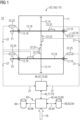
- the internal control unit 42 is connected to another control unit 40, which is designed as a higher-level control unit 44.
- the control units 40 are communicatively coupled to one another via a data connection 45.
- a computer program product 80 is stored in non-volatile form on both control units 40 and is also executed during operation of the transmission 10.
- the computer program products 80 are suitable for processing the received measurement data 27 and are designed to implement the method 100 according to the invention using the measurement data 27 on the transmission 10.
- the data connection 45 also allows parameters 73 to be exchanged between the internal control unit 42 and the higher-level control unit 44, which parameters influence the sequence of the method 100.
- the parameters 73 which are used in the internal control unit 42 for the sequence of the method 100, can thus be set in terms of type and value by the higher-level control unit 44 as a default 77.
- specifications 77 for the method 100 are interchangeable between the higher-level control unit 44 and the internal control unit 42, which are specified by an algorithm 79.
- Such an algorithm 79 can be executed on the internal control unit 42 and the higher-level control unit 44.
- the specifications 77 can also be generated by a user input 78, which is made at the higher-level control unit 44.
- the higher-level control unit 44 is also communicatively coupled to a database 60 via a data connection 45. Data records 64 of comparison components 62 are stored in the database 60 and can also be forwarded to the internal control unit 42 as parameters 73.
- the data sets 64 are continuously updated using a plurality of comparison components 62 so that the experience of users of identical comparison components 62 can be used for the transmission component 12.
- an updated distribution function 51 among other things, unforeseen long lifetimes, i.e. unforeseen high damage amounts 43 up to failure, of transmission components 12 can be exploited during operation. Conversely, surprisingly short service lives, i.e., low damage sums 43 up to failure, can be taken into account.
- a dynamic monitoring system 90 is implemented that becomes more reliable and precise in predicting failure of transmission components 12 with increasing operating time.
- An adjustable first threshold value 75 is defined for both the model remaining service life 36. If the model remaining service life 36 falls below the first threshold value 75, a warning 65 and/or a stockpiling instruction 66 is triggered. This warns a user of an impending failure of the transmission component 12 or prompts the provision of a replacement part.
- an adjustable second threshold value 76 is specified for the probability of occurrence 57. If the probability of occurrence 57 falls below the second threshold value 76, a warning 65 and/or a stockpiling instruction 66 is also issued for the transmission component 12.
- the first and second threshold values 75, 76 belong to the parameters 73, which, as in FIG 1 shown, influence the course of the procedure 100 and can be specified by a user input 78 or an algorithm 79.
- the sequence of a second embodiment of the claimed method 100 is shown schematically.
- the method 100 is based on a first method step 110 in which the transmission 10 is provided with the plurality of transmission components 12, wherein at least a first transmission component 12 is to be monitored.
- the transmission 10 is in an operating state 20 in which a mechanical stress 25 on the first transmission component 12 is determined using a sensor 22.
- a second method step 120 in which, based on the mechanical stress 25, a corresponding damage contribution 35 is determined within the framework of an adjustable damage accumulation model 30 and an adjustable first damage mechanism 38.
- the damage contribution 35 is added to a damage sum 43 in the damage accumulation model 30 for the first damage mechanism 38.
- a sixth method step 160 is carried out in which, based on the model remaining service life 36 and the probability of occurrence 57, a cost forecast 67 for a maintenance process for the first transmission component 12 is carried out. A result of the Effort forecast 67 can be displayed to a user.
- the fourth method step 140 is followed by a first branch 145, at which the model remaining service life 36 and/or the probability of occurrence 57 from the fourth method step 140 are compared with adjustable parameters 73.
- the adjustable parameters 73 also include a first and a second threshold value 75, 76 for the model remaining service life 36 and the probability of occurrence 57, respectively.
- the method 100 returns to the first method step 110 via a feedback loop 170. If the model remaining service life 36 or the probability of occurrence 57 falls below the first and/or second threshold value 75, 76, a fifth method step 150 is executed. In this step, a warning 65 is issued and/or a stockpiling instruction 66 is issued for the first transmission component 12. Subsequently, the method 100 reaches a final state 200.
- the method 100 according to FIG 4 runs completely or functionally divided in one or more computer program products 80, which are stored in a non-volatile and executable manner on a control unit 40.
- the control unit 40 comprises an internal control unit 42 and/or a higher-level control unit 44.
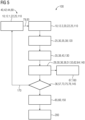
- FIG 5 shows a schematic sequence of a third embodiment of the claimed method 100.
- the method 100 is based on a first method step 110, in which a mechanical stress 25 of a first transmission component 12.1 in an operating state 20 is determined by means of a sensor 22.
- a transfer function 83 Based on a transfer function 83, a mechanical stress 25 of a second transmission component 12.2 in the same operating state 20 is determined.
- the first and second transmission components 12.1 and 12.2 belong to the same transmission 10.
- a transfer function 83 is to be understood as a physical relationship between the first and second transmission components 12.1, 12.2, which determines a mechanical stress 25 of the first transmission component 12.1 essentially as a function of the mechanical stress 25 of the second transmission component 12.2.
- Such a transfer function 83 can be designed as a value table, as an algorithm 79, or as a simulation. Based on the mechanical stress 25 of the second transmission component 12.2, the second, third, fourth, fifth, and sixth method steps 120, 130, 140, 150, 160 are carried out analogously to FIG 4 .
- the first method step 110 is followed by a second method step 120, in which, based on the mechanical stress 25, a corresponding damage contribution 35 is determined within the framework of an adjustable damage accumulation model 30 and an adjustable first damage mechanism 38.
- a corresponding damage contribution 35 is determined within the framework of an adjustable damage accumulation model 30 and an adjustable first damage mechanism 38.
- the damage contribution 35 is added to a damage sum 43 in the damage accumulation model 30 for the first damage mechanism 38.
- a model remaining service life 36 is determined for the first damage mechanism 38 within the framework of the damage accumulation model 30.
- a probability of occurrence 57 for the corresponding model remaining service life 36 is determined.
- the determination of the model remaining service life 36 and its probability of occurrence 57 is based on an adjustable load level 29, which corresponds to an expected or desired future operation of the second transmission component 12.2, and thus of the transmission 10.
- the probability of occurrence 57 is determined using data sets 64 of comparison components 62, which provide a distribution function 51 of service lives.
- a sixth method step 160 takes place, in which, based on the model remaining service life 36 and the probability of occurrence 57, a cost forecast 67 for a maintenance process for the second transmission component 12.2 is performed.
- the result of the cost forecast 67 can be displayed to a user.
- the fourth method step 140 is followed by a first branching 145, at which the model remaining service life 36 and/or the probability of occurrence 57 from the fourth method step 140 are compared with adjustable parameters 73.
- the adjustable parameters 73 also include a first and a second threshold value 75, 76 for the model remaining service life 36 and the probability of occurrence 57, respectively. If the threshold values 75, 76 are exceeded, it is recognized that no operating state exists that requires a reaction, and the method 100 returns to the first method step 110 via a feedback loop 170. If the model remaining service life 36 and/or the probability of occurrence 57 fall below the first and/or second threshold value 75, 76, a fifth method step 150 takes place.
- a warning 65 is issued and/or a stockpiling instruction 66 is issued for the second transmission component 12.2.
- the method 100 reaches a final state 200.
- the method 100 after FIG 5 runs completely or functionally divided in one or more computer program products 80, which are stored in a non-volatile and executable manner on a control unit 40.
- the control unit 40 comprises an internal control unit 42 and/or a higher-level control unit 44.
- the structure of a first embodiment of the claimed monitoring system 90 is shown in FIG 6 shown.
- the monitoring system 90 comprises a plurality of sensors 22, which are designed to directly or indirectly detect a mechanical stress 25 on a transmission component 12 of a transmission 10.
- measurement data 27 is transmitted from the sensors 22 to a control unit 40, which includes an internal control unit 42.
- a computer program product 80 is stored in a memory of the internal control unit 42 in a non-volatile form in an executable manner.
- the internal control unit 42 is designed to receive the measurement data 27 from the sensors 22 and to process it with the computer program product 80.
- the computer program product 80 has a first subprogram 82, which is stored in a non-volatile, executable manner on the first control unit 42.
- the claimed method 100 is partially implemented in at least one embodiment by the first subprogram 82.
- the first subprogram 82 is communicatively coupled to a higher-level control unit 44 via a data connection 45.
- a second subprogram 84 which belongs to the same computer program product 80 as the first subprogram 82, is stored non-volatilely and executably on the higher-level control unit 44.
- the second subprogram 84 belongs to the same computer program product 80 as the first subprogram 82.
- the communicative data connection 45 between the internal and higher-level control units 42, 44 enables communication between the first and second subprograms 82, 84.
- the second subprogram 84 partially implements the claimed method 100.
- the first and second subprograms 82, 84 interacting together completely implement the claimed method 100 via the communicative data connection 45.
- the first and second subprograms 82, 84 exchange parameters 73, values from specifications 77 and/or values from algorithms 79.
- FIG 7 shows a schematic structure of a claimed transmission application 95, which comprises a drive unit 96, an output unit 97, and a transmission 10.
- the transmission 10 is mounted between the drive unit 96 and the output unit 97. Through the transmission 10, a drive power 21 from the drive unit 96, modified in terms of speed and torque, is transmitted as output power 23 to the output unit 97.
- the transmission application 95 can be designed as an industrial application, as a wind turbine, as a land vehicle, as a watercraft, or as an aircraft.
Landscapes
- Business, Economics & Management (AREA)
- Physics & Mathematics (AREA)
- General Physics & Mathematics (AREA)
- Engineering & Computer Science (AREA)
- Human Resources & Organizations (AREA)
- Economics (AREA)
- Entrepreneurship & Innovation (AREA)
- Quality & Reliability (AREA)
- Strategic Management (AREA)
- Tourism & Hospitality (AREA)
- Operations Research (AREA)
- General Business, Economics & Management (AREA)
- Marketing (AREA)
- Theoretical Computer Science (AREA)
- Accounting & Taxation (AREA)
- Finance (AREA)
- Development Economics (AREA)
- Testing Of Devices, Machine Parts, Or Other Structures Thereof (AREA)
Claims (16)
- Procédé de fonctionnement (100) pour un engrenage (10) pour une application d'engrenage conçu sous la forme d'une éolienne ou d'une application industrielle, ayant une pluralité de composants d'engrenage (12, 12.1, 12.2), comprenant les étapes suivantes :a) établissement d'un état de fonctionnement (20) de l'engrenage (10) et détection d'une sollicitation mécanique (25) correspondante d'un premier composant d'engrenage (12, 12.1) ;b) détermination d'une contribution à l'endommagement (35) sur le premier composant d'engrenage (12, 12.1) en utilisant la sollicitation mécanique (25) déterminée pour un premier mécanisme d'endommagement (38) ;c) ajout de la contribution à l'endommagement (35) à une somme de dommages (43) dans un premier modèle d'accumulation de dommages (30) du premier mécanisme de dommages (38) ;d) détermination d'une durée de vie résiduelle de modèle (36) du premier composant d'engrenage (12, 12.1) en utilisant le premier modèle d'accumulation de dommages (30) et détermination d'une probabilité d'occurrence (57) pour la durée de vie résiduelle de modèle (36) ;la probabilité d'occurrence (57) pour la durée de vie résiduelle (36) du modèle étant déterminée en utilisant des ensembles de données (64) de composants de comparaison (62) qui sont de construction identique au premier composant d'engrenage (12, 12.1), une contribution à l'endommagement (35) étant déterminée à l'étape b) également pour un deuxième mécanisme d'endommagement (39) et les étapes c) et d) étant exécutées en utilisant celui-ci également pour un deuxième mécanisme d'endommagement (39), ce qui comprend une détermination d'une somme de dommages (43) pour le deuxième mécanisme d'endommagement (39), caractérisé en ce queau moins une durée de vie de modèle (36) et sa probabilité d'occurrence (57) sont enregistrées dans un ensemble de données (64), qui présente une information sur le type du mécanisme d'endommagement correspondant,l'ensemble de données (64) servant d'ensemble de données de comparaison (64) pour d'autres composants d'engrenage (62) de construction identique et les composants de comparaison (62) étant utilisés dans des engrenages tiers, l'engrenage tiers étant un engrenage différent de l'engrenage (10) dans une autre application d'engrenage.
- Procédé de fonctionnement (100) selon la revendication 1, caractérisé en ce qu'au moins une sollicitation mécanique (25) détectée est mémorisée dans l'ensemble de données (64).
- Procédé de fonctionnement (100) selon la revendication 1 ou la revendication 2, caractérisé en ce qu'au moins une contribution à l'endommagement (25) et/ou au moins une somme d'endommagement (43) sont enregistrées dans l'enregistrement de données (64).
- Procédé de fonctionnement (100) selon les revendications 1 à 3, caractérisé en ce que dans une autre étape e), un avertissement (65) est émis si la durée de vie résiduelle (36) du modèle est inférieure à une première valeur seuil (75) réglable et/ou la probabilité d'occurrence (57) tombe en dessous d'une deuxième valeur seuil (76) réglable.
- Procédé de fonctionnement (100) selon l'une des revendications 1 à 4, caractérisé en ce qu'à l'étape b), une sollicitation mécanique (25) d'un deuxième composant d'engrenage (12.2) est déterminée en utilisant la sollicitation mécanique (25) du premier composant d'engrenage (12, 12.1) au moyen d'une fonction de transfert (83), et au moins les étapes c) et d) sont également exécutées pour le deuxième composant d'engrenage (12.2).
- Procédé de fonctionnement (100) selon l'une des revendications 1 à 5, caractérisé en ce que le premier ou le deuxième mécanisme d'endommagement (38, 39) est réalisé sous forme de fatigue cyclique élevée (« High-Cycle-Fatigue »), une fatigue cyclique faible (« Low-Cycle-Fatigue »), une usure, une rupture de racine de dent ou de d'endommagement (« pitting ») sur une denture.
- Procédé de fonctionnement (100) selon l'une des revendications 1 à 6, caractérisé en ce que la probabilité d'occurrence (57) pour la durée de vie résiduelle du modèle (36) est déterminée en utilisant une fonction de distribution (51) de sommes de dommages admissibles (43) des composants de comparaison (62).
- Procédé de fonctionnement (100) selon l'une des revendications 1 à 7, caractérisé en ce que la somme de dommages (43) est apte à être réglée au moyen d'un algorithme (79) et/ou d'une entrée utilisateur (78).
- Procédé de fonctionnement (100) selon l'une des revendications 1 à 8, caractérisé en ce qu'un coût de réparation (67) à prévoir pour le premier composant de l'engrenage (12, 121) et/ou l'engrenage (10) est déterminé au moyen de la durée de vie résiduelle du modèle (36) et/ou de sa probabilité d'occurrence (57).
- Procédé de fonctionnement (100) selon la revendication 9, caractérisé en ce qu'au moins pour le premier composant d'engrenage (12, 12.1), une instruction d'approvisionnement (66) est émise à un système de gestion de matériel (68).
- Procédé de fonctionnement (100) selon l'une des revendications 1 à 10, caractérisé en ce que la durée de vie résiduelle du modèle (36) et/ou sa probabilité d'occurrence (57) est déterminée en utilisant un niveau de charge réglable (29) pour une poursuite de l'exploitation du premier composant de l'engrenage (12, 12.1).
- Produit de programme informatique (80), comprenant au moins un sous-programme (82), qui est conçu pour mettre en œuvre un procédé de fonctionnement (100) pour un engrenage (10) entièrement ou au moins partiellement en liaison de données (45) avec un deuxième sous-programme (84), caractérisé en ce que le procédé de fonctionnement (100) est conçu selon l'une des revendications 1 à 11.
- Unité de commande (40) pour un engrenage (10), qui présente une mémoire et une unité de calcul pour l'exécution d'un produit de programme informatique (80), caractérisée en ce que le produit de programme informatique (80) est conçu selon la revendication 12, et en ce que l'unité de commande (40) est agencée en tant qu'unité de commande interne (42) sur l'engrenage (10), ou est installée comme unité de commande supérieure (44) séparément de l'engrenage (10).
- Système de surveillance (90) pour un engrenage (10), qui est apte à être relié à au moins un premier composant d'engrenage (12, 12.1) à surveiller, comprenant une pluralité de capteurs (22) pour une saisie de données de mesure (27) qui correspondent à une sollicitation mécanique (25) du premier composant d'engrenage (12, 12.1), et au moins une unité de commande (40) qui est reliée à la pluralité de capteurs (22) et qui est conçue sous la forme d'une unité de commande interne (42) et/ou d'une unité de commande supérieure (44), caractérisé en ce que l'unité de commande (44) est conçue selon la revendication 13.
- Engrenage (10), comprenant une pluralité de composants d'engrenage (12, 12.1, 12.2), au moins un premier composant d'engrenage (12, 12.1) étant relié à au moins un capteur (22), le capteur (22) étant associé à un système de surveillance (90), caractérisé en ce que le système de surveillance (90) est réalisé selon la revendication 14.
- Application d'engrenage (95), comprenant un engrenage (10) placé entre une unité d'entraînement (96) et une unité de sortie (97) pour modifier la vitesse de rotation, l'application d'engrenage (95) étant conçue sous la forme d'une éolienne ou d'une application industrielle, caractérisée en ce que l'engrenage (10) est conçu selon la revendication 15.
Applications Claiming Priority (2)
| Application Number | Priority Date | Filing Date | Title |
|---|---|---|---|
| EP18202907.4A EP3644037A1 (fr) | 2018-10-26 | 2018-10-26 | Procédé de fonctionnement amélioré pour engrenage |
| PCT/EP2019/074990 WO2020083573A1 (fr) | 2018-10-26 | 2019-09-18 | Procédé amélioré permettant de faire fonctionner une transmission |
Publications (3)
| Publication Number | Publication Date |
|---|---|
| EP3833954A1 EP3833954A1 (fr) | 2021-06-16 |
| EP3833954B1 true EP3833954B1 (fr) | 2025-03-12 |
| EP3833954C0 EP3833954C0 (fr) | 2025-03-12 |
Family
ID=64082892
Family Applications (2)
| Application Number | Title | Priority Date | Filing Date |
|---|---|---|---|
| EP18202907.4A Withdrawn EP3644037A1 (fr) | 2018-10-26 | 2018-10-26 | Procédé de fonctionnement amélioré pour engrenage |
| EP19778881.3A Active EP3833954B1 (fr) | 2018-10-26 | 2019-09-18 | Procédé de fonctionnement amélioré pour engrenage |
Family Applications Before (1)
| Application Number | Title | Priority Date | Filing Date |
|---|---|---|---|
| EP18202907.4A Withdrawn EP3644037A1 (fr) | 2018-10-26 | 2018-10-26 | Procédé de fonctionnement amélioré pour engrenage |
Country Status (4)
| Country | Link |
|---|---|
| US (1) | US20210381928A1 (fr) |
| EP (2) | EP3644037A1 (fr) |
| CN (1) | CN112912707B (fr) |
| WO (1) | WO2020083573A1 (fr) |
Families Citing this family (4)
| Publication number | Priority date | Publication date | Assignee | Title |
|---|---|---|---|---|
| JP6753442B2 (ja) * | 2018-09-10 | 2020-09-09 | 日本電気株式会社 | モデル生成装置、モデル生成方法、及びプログラム |
| CN114861474B (zh) * | 2022-07-08 | 2022-10-04 | 西南交通大学 | 一种智能泵阀系统性能仿真处理方法及云计算服务系统 |
| AT527442B1 (de) * | 2023-08-04 | 2025-04-15 | Uptime Holding Gmbh | Verfahren zur Bestimmung eines Zustandes eines technischen Systems |
| TWI869150B (zh) * | 2024-01-02 | 2025-01-01 | 財團法人工業技術研究院 | 傳動模組及其傳動件壽命預測方法 |
Family Cites Families (13)
| Publication number | Priority date | Publication date | Assignee | Title |
|---|---|---|---|---|
| US5210704A (en) * | 1990-10-02 | 1993-05-11 | Technology International Incorporated | System for prognosis and diagnostics of failure and wearout monitoring and for prediction of life expectancy of helicopter gearboxes and other rotating equipment |
| SE517970C2 (sv) * | 2000-07-20 | 2002-08-13 | Volvo Articulated Haulers Ab | Förfarande för att uppskatta en livslängdsreducerande skada på ett i drift belastat objekt,jämte datorprogramprodukt |
| US6745153B2 (en) * | 2001-11-27 | 2004-06-01 | General Motors Corporation | Data collection and manipulation apparatus and method |
| US6834256B2 (en) * | 2002-08-30 | 2004-12-21 | General Electric Company | Method and system for determining motor reliability |
| US7149657B2 (en) * | 2003-06-23 | 2006-12-12 | General Electric Company | Method, system and computer product for estimating a remaining equipment life |
| US7328128B2 (en) * | 2006-02-22 | 2008-02-05 | General Electric Company | Method, system, and computer program product for performing prognosis and asset management services |
| US7606673B2 (en) | 2006-05-01 | 2009-10-20 | Dynamic Measurement Consultants, Llc | Rotating bearing analysis and monitoring system |
| DE102007017614A1 (de) | 2007-04-12 | 2008-10-16 | Wittenstein Ag | Verfahren zum optimalen Betreiben von Getrieben |
| GB0807775D0 (en) * | 2008-04-29 | 2008-06-04 | Romax Technology Ltd | Methods for model-based diagnosis of gearbox |
| EP2264314B1 (fr) * | 2009-05-25 | 2016-05-25 | Vestas Wind Systems A/S | Procédé et système pour contrôler le fonctionnement d'une éolienne |
| US8364424B2 (en) | 2010-07-30 | 2013-01-29 | General Electric Company | System and method for monitoring a wind turbine gearbox |
| CN104335023A (zh) * | 2012-04-24 | 2015-02-04 | Skf公司 | 轴承监控方法和系统 |
| DE102012015485A1 (de) * | 2012-08-07 | 2014-05-15 | Prüftechnik Dieter Busch AG | Verfahren zum Überwachen von rotierenden Maschinen |
-
2018
- 2018-10-26 EP EP18202907.4A patent/EP3644037A1/fr not_active Withdrawn
-
2019
- 2019-09-18 WO PCT/EP2019/074990 patent/WO2020083573A1/fr not_active Ceased
- 2019-09-18 EP EP19778881.3A patent/EP3833954B1/fr active Active
- 2019-09-18 CN CN201980070462.1A patent/CN112912707B/zh active Active
- 2019-09-18 US US17/288,335 patent/US20210381928A1/en active Pending
Also Published As
| Publication number | Publication date |
|---|---|
| US20210381928A1 (en) | 2021-12-09 |
| EP3833954A1 (fr) | 2021-06-16 |
| WO2020083573A1 (fr) | 2020-04-30 |
| EP3644037A1 (fr) | 2020-04-29 |
| EP3833954C0 (fr) | 2025-03-12 |
| CN112912707A (zh) | 2021-06-04 |
| CN112912707B (zh) | 2023-08-25 |
Similar Documents
| Publication | Publication Date | Title |
|---|---|---|
| EP3833954B1 (fr) | Procédé de fonctionnement amélioré pour engrenage | |
| DE102016105877B4 (de) | Verfahren und Vorrichtung zur Überwachung einer Maschine | |
| EP1423827B1 (fr) | Dispositif et procede de detection precoce et de prediction de deteriorations d'unites | |
| EP3729040B1 (fr) | Procédé basé sur un modèle et système de surveillance d'état d'un palier lisse, en particulier pour des éoliennes | |
| EP2696251B1 (fr) | Procédé de surveillance de machines rotatives | |
| EP2549257B1 (fr) | Procédé de détection de dommages sur des engrenages | |
| EP4468228A2 (fr) | Maintenance anticipée pour un dispositif dans l'industrie alimentaire au moyen d'un jumeau numérique et planification de production optimisée | |
| DE102019210795A1 (de) | Spannungswellengetriebe und Verfahren für Spannungswellengetriebe | |
| DE102017003165A1 (de) | Maschinelle Lernvorrichtung und maschinelles Lernverfahren zum Lernen der Fehlervorhersage einer Hauptwelle oder eines Motors, der die Hauptwelle antreibt, und Fehlervorhersagevorrichtung und Fehlervorhersagesystem umfassend eine maschinelle Lernvorrichtung | |
| EP2927662B1 (fr) | Procédé et système de surveillance de l'état d'un palier de roulement d'une éolienne | |
| WO2012055699A1 (fr) | Système d'information de maintenance, capteur d'état à utiliser dans ce système et procédé pouvant être mis en oeuvre au moyen de ce système pour décider de la nécessité d'effectuer une maintenance | |
| EP1892597A1 (fr) | Surveillance de machines et d'installations techniques | |
| DE102019108278A1 (de) | Vorrichtung zum Ermitteln des Ist-Zustands und/oder der Restlebensdauer einer Baumaschine | |
| EP3273414A1 (fr) | Procédé d'estimation d'une durée de vie attendue d'un composant d'une machine | |
| DE112013007431T5 (de) | Vorrichtung, Verfahren & Rechnerprogrammprodukt | |
| EP2674581A1 (fr) | Composants de machine d'une chaîne cinématique ainsi que la méthode de conception et/ou de mettre en service et/ou d'opération d'une telle chaîne cinématique | |
| EP3611588A1 (fr) | Dispositif et procédé de prévision d'une durée de vie d'une machine | |
| EP3841366A1 (fr) | Procédé et système pour la détermination directe d'un endommagement théorique d'au moins un organe d'un dispositif | |
| WO2017036615A1 (fr) | Procédé de pronostic assisté par ordinateur d'états de fonctionnement futurs de composants de machine | |
| EP3954831A1 (fr) | Machine de compactage du sol | |
| EP4348825A1 (fr) | Procédé et dispositif de surveillance pour surveiller l'état d'une machine | |
| EP4291885B1 (fr) | Appareil de détermination de l'état réel et/ou de la durée de vie restante de composants structuraux d'une machine de travail | |
| EP4310614A1 (fr) | Procédé ou dispositif d'utilisation d'un modèle de données pour surveiller ou évaluer un transporteur à courroie | |
| DE102024105139B4 (de) | Verfahren zum Konfigurieren einer Anomaliedetektionseinrichtung, Verfahren zur Detektion von Anomalien eines Wellgetriebes, Trainingsdatensatz | |
| EP3907485A1 (fr) | Procédé de surveillance amélioré pour un composant de transmission |
Legal Events
| Date | Code | Title | Description |
|---|---|---|---|
| STAA | Information on the status of an ep patent application or granted ep patent |
Free format text: STATUS: UNKNOWN |
|
| STAA | Information on the status of an ep patent application or granted ep patent |
Free format text: STATUS: THE INTERNATIONAL PUBLICATION HAS BEEN MADE |
|
| PUAI | Public reference made under article 153(3) epc to a published international application that has entered the european phase |
Free format text: ORIGINAL CODE: 0009012 |
|
| STAA | Information on the status of an ep patent application or granted ep patent |
Free format text: STATUS: REQUEST FOR EXAMINATION WAS MADE |
|
| 17P | Request for examination filed |
Effective date: 20210312 |
|
| AK | Designated contracting states |
Kind code of ref document: A1 Designated state(s): AL AT BE BG CH CY CZ DE DK EE ES FI FR GB GR HR HU IE IS IT LI LT LU LV MC MK MT NL NO PL PT RO RS SE SI SK SM TR |
|
| DAV | Request for validation of the european patent (deleted) | ||
| DAX | Request for extension of the european patent (deleted) | ||
| STAA | Information on the status of an ep patent application or granted ep patent |
Free format text: STATUS: EXAMINATION IS IN PROGRESS |
|
| 17Q | First examination report despatched |
Effective date: 20220325 |
|
| GRAP | Despatch of communication of intention to grant a patent |
Free format text: ORIGINAL CODE: EPIDOSNIGR1 |
|
| STAA | Information on the status of an ep patent application or granted ep patent |
Free format text: STATUS: GRANT OF PATENT IS INTENDED |
|
| GRAS | Grant fee paid |
Free format text: ORIGINAL CODE: EPIDOSNIGR3 |
|
| INTG | Intention to grant announced |
Effective date: 20241018 |
|
| GRAA | (expected) grant |
Free format text: ORIGINAL CODE: 0009210 |
|
| STAA | Information on the status of an ep patent application or granted ep patent |
Free format text: STATUS: THE PATENT HAS BEEN GRANTED |
|
| AK | Designated contracting states |
Kind code of ref document: B1 Designated state(s): AL AT BE BG CH CY CZ DE DK EE ES FI FR GB GR HR HU IE IS IT LI LT LU LV MC MK MT NL NO PL PT RO RS SE SI SK SM TR |
|
| REG | Reference to a national code |
Ref country code: GB Ref legal event code: FG4D Free format text: NOT ENGLISH |
|
| REG | Reference to a national code |
Ref country code: CH Ref legal event code: EP |
|
| REG | Reference to a national code |
Ref country code: DE Ref legal event code: R096 Ref document number: 502019013056 Country of ref document: DE |
|
| REG | Reference to a national code |
Ref country code: IE Ref legal event code: FG4D Free format text: LANGUAGE OF EP DOCUMENT: GERMAN |
|
| U01 | Request for unitary effect filed |
Effective date: 20250312 |
|
| U07 | Unitary effect registered |
Designated state(s): AT BE BG DE DK EE FI FR IT LT LU LV MT NL PT RO SE SI Effective date: 20250318 |
|
| PG25 | Lapsed in a contracting state [announced via postgrant information from national office to epo] |
Ref country code: RS Free format text: LAPSE BECAUSE OF FAILURE TO SUBMIT A TRANSLATION OF THE DESCRIPTION OR TO PAY THE FEE WITHIN THE PRESCRIBED TIME-LIMIT Effective date: 20250612 |
|
| PG25 | Lapsed in a contracting state [announced via postgrant information from national office to epo] |
Ref country code: ES Free format text: LAPSE BECAUSE OF FAILURE TO SUBMIT A TRANSLATION OF THE DESCRIPTION OR TO PAY THE FEE WITHIN THE PRESCRIBED TIME-LIMIT Effective date: 20250312 |
|
| PG25 | Lapsed in a contracting state [announced via postgrant information from national office to epo] |
Ref country code: NO Free format text: LAPSE BECAUSE OF FAILURE TO SUBMIT A TRANSLATION OF THE DESCRIPTION OR TO PAY THE FEE WITHIN THE PRESCRIBED TIME-LIMIT Effective date: 20250612 |
|
| PG25 | Lapsed in a contracting state [announced via postgrant information from national office to epo] |
Ref country code: HR Free format text: LAPSE BECAUSE OF FAILURE TO SUBMIT A TRANSLATION OF THE DESCRIPTION OR TO PAY THE FEE WITHIN THE PRESCRIBED TIME-LIMIT Effective date: 20250312 |
|
| PG25 | Lapsed in a contracting state [announced via postgrant information from national office to epo] |
Ref country code: GR Free format text: LAPSE BECAUSE OF FAILURE TO SUBMIT A TRANSLATION OF THE DESCRIPTION OR TO PAY THE FEE WITHIN THE PRESCRIBED TIME-LIMIT Effective date: 20250613 |
|
| PG25 | Lapsed in a contracting state [announced via postgrant information from national office to epo] |
Ref country code: SM Free format text: LAPSE BECAUSE OF FAILURE TO SUBMIT A TRANSLATION OF THE DESCRIPTION OR TO PAY THE FEE WITHIN THE PRESCRIBED TIME-LIMIT Effective date: 20250312 |
|
| PG25 | Lapsed in a contracting state [announced via postgrant information from national office to epo] |
Ref country code: PL Free format text: LAPSE BECAUSE OF FAILURE TO SUBMIT A TRANSLATION OF THE DESCRIPTION OR TO PAY THE FEE WITHIN THE PRESCRIBED TIME-LIMIT Effective date: 20250312 |
|
| PGFP | Annual fee paid to national office [announced via postgrant information from national office to epo] |
Ref country code: TR Payment date: 20250909 Year of fee payment: 7 |
|
| PG25 | Lapsed in a contracting state [announced via postgrant information from national office to epo] |
Ref country code: CZ Free format text: LAPSE BECAUSE OF FAILURE TO SUBMIT A TRANSLATION OF THE DESCRIPTION OR TO PAY THE FEE WITHIN THE PRESCRIBED TIME-LIMIT Effective date: 20250312 |
|
| U20 | Renewal fee for the european patent with unitary effect paid |
Year of fee payment: 7 Effective date: 20250917 |
|
| PG25 | Lapsed in a contracting state [announced via postgrant information from national office to epo] |
Ref country code: SK Free format text: LAPSE BECAUSE OF FAILURE TO SUBMIT A TRANSLATION OF THE DESCRIPTION OR TO PAY THE FEE WITHIN THE PRESCRIBED TIME-LIMIT Effective date: 20250312 |
|
| PG25 | Lapsed in a contracting state [announced via postgrant information from national office to epo] |
Ref country code: IS Free format text: LAPSE BECAUSE OF FAILURE TO SUBMIT A TRANSLATION OF THE DESCRIPTION OR TO PAY THE FEE WITHIN THE PRESCRIBED TIME-LIMIT Effective date: 20250712 |
|
| PLBE | No opposition filed within time limit |
Free format text: ORIGINAL CODE: 0009261 |
|
| STAA | Information on the status of an ep patent application or granted ep patent |
Free format text: STATUS: NO OPPOSITION FILED WITHIN TIME LIMIT |
|
| REG | Reference to a national code |
Ref country code: CH Ref legal event code: L10 Free format text: ST27 STATUS EVENT CODE: U-0-0-L10-L00 (AS PROVIDED BY THE NATIONAL OFFICE) Effective date: 20260121 |
|
| 26N | No opposition filed |
Effective date: 20251215 |