EP2700553A1 - Pont d'un passage avec un soufflet circonférentiel en forme de tunnel entre deux véhicules reliés par une liaison articulée - Google Patents
Pont d'un passage avec un soufflet circonférentiel en forme de tunnel entre deux véhicules reliés par une liaison articulée Download PDFInfo
- Publication number
- EP2700553A1 EP2700553A1 EP12005984.5A EP12005984A EP2700553A1 EP 2700553 A1 EP2700553 A1 EP 2700553A1 EP 12005984 A EP12005984 A EP 12005984A EP 2700553 A1 EP2700553 A1 EP 2700553A1
- Authority
- EP
- European Patent Office
- Prior art keywords
- bridge
- vehicle
- tunnel
- transition
- bellows
- Prior art date
- Legal status (The legal status is an assumption and is not a legal conclusion. Google has not performed a legal analysis and makes no representation as to the accuracy of the status listed.)
- Granted
Links
Images




Classifications
-
- B—PERFORMING OPERATIONS; TRANSPORTING
- B61—RAILWAYS
- B61D—BODY DETAILS OR KINDS OF RAILWAY VEHICLES
- B61D17/00—Construction details of vehicle bodies
- B61D17/04—Construction details of vehicle bodies with bodies of metal; with composite, e.g. metal and wood body structures
- B61D17/20—Communication passages between coaches; Adaptation of coach ends therefor
Definitions
- the invention relates to a bridge of a transition with a tunnel-shaped circulating bellows between two interconnected by an articulated vehicle, the bridge comprising a tread plate and two floor panels, each floor panel is in the region of the front of a vehicle with the vehicle in communication, said Tread plate rests on the bottom plates, wherein for centering the Tread plate is provided relative to the bottom plates in the passage direction on the underside of the bridge at least one centering, wherein the at least one centering member is on the one hand with the tread plate and on the other hand with the respective vehicle in combination.
- Bridges of the type mentioned are known.
- link bridges are known, which are used in short coupled vehicles with central buffer coupling.
- the use of link bridges in such short-coupled vehicles with central buffer coupling takes place insofar as sets in these vehicles when driving through curves, a relatively high transverse offset.
- Link bridges as for example from the EP 0331121 A2 are known, are in principle able to meet the requirements for the transverse offset when passing through curves.
- Other embodiments of link bridges are for example from the EP 0669243B1 , the EP 0958981 B1 and also from the EP 0722873 B1 known.
- bridge constructions consisting essentially of a so-called tread plate, which rests laterally on a respective bottom plate, wherein the two bottom plates are each hinged to a vehicle part.
- devices are disposed under the tread plate, which engage under the bottom plate.
- a bridge of the type described above is for example from the EP 2157006 A1 known or even from the EP 1564101 B1 .
- Such bridges have been used in vehicles that have bogies, for example, so-called Jakobs bogies. In a multi-unit vehicle in which the individual vehicle parts rest on such Jakobs bogies, occurs essentially no cross-offset when driving through curves.
- the articulated connection is in this case designed in particular as a central buffer coupling.
- Each base plate is in the region of the front of the vehicle with the vehicle in conjunction.
- at least one centering member is provided on the underside of the bridge. This one centering is on the one hand with the tread plate and on the other hand with the respective vehicle in conjunction, so that the tread plate is always centered centered between the two vehicles on the two floor panels.
- the transition includes a bellows next to the bridge.
- the bellows may be formed tunnel-shaped circumferential between the articulated connection on the one hand and the bridge on the other hand, but it may also include the articulated connection, in particular a central buffer coupling.
- the space below the bridge which, as already stated, is formed by the tread plate and the two bottom plates, is not hermetically sealed by the bridge. Especially in winter, dirt, salt, grit and the like accumulates in the bottom area of the bellows. In addition, there is often water on the bottom of the bellows or even ice in winter.
- the object underlying the invention is therefore to ensure at a bridge of a transition between two interconnected by an articulated connection vehicles of the type mentioned in that the bottom of the bellows is to clean without restrictions and the clutch is optionally accessible.
- the invention proposes that between the at least one centering member and the respective vehicle a first or a second connection means is provided, wherein the first and the second connection means are formed such that the at least one centering member from the region of the bellows bottom can be brought , If on both sides of the central longitudinal axis of the vehicle, in each case such a centering member is provided, which is designed in particular as a scissors-type frame and in particular as a pair of scissors, both centering members should be able to be brought together from the region of the bellows base.
- a releasable connection is provided.
- the first connecting means comprises a pivot joint, wherein the pivot joint is in communication with the one vehicle, wherein the other second connecting means forms a detachable connection with the other vehicle ,
- the first connection device comprises a first carrier arranged on the first base plate, which receives the one end of the at least one centering element.
- a first carrier in the horizontal position of the at least one centering member is mounted on a first cross member arranged on the vehicle, wherein the cross member may be connected to the vehicle by the pivot joint.
- the connecting device comprises both the carrier and the cross member, but the traverse forms the bearing point for the carrier.
- the bottom plate is pivotally mounted on the first pivot joint.
- the first pivot joint itself is located on the vehicle, in particular in the region of the front side of the car body of the vehicle.
- the second base plate has a second carrier for receiving the at least one second end of the at least one centering member.
- the second bracket communicates with the second floor panel through a second pivot joint, the second pivot joint further showing an overlap panel to the floor of the vehicle.
- the second carrier rests on a arranged on the corresponding second vehicle second crossmember, which is arranged on the end face of this second vehicle.
- the second carrier is releasably connected by a locking device with the second vehicle.
- the locking device has a finger which can be disengaged from an opening arranged on the carrier.
- a wall which has a corresponding opening for the finger.
- the finger itself is mounted in a bearing block, wherein the bearing block is fixed to the front side of the vehicle.
- the axial displaceability of the finger can be carried out by, for example, pivoting a lever via a rotatable square, wherein the one end of the finger is articulated to the lever in an articulated manner.
- the finger is under the load of a spring, so that while driving, that is, in the position of use of the bridge, the finger is kept pressed by the spring in the opening.
- This type of locking is advantageously provided on both sides of the bridge, that is to say with respect to the support on each side of the bridge, so that to remove the tread plate with the centering members, the locking devices on each side of the bridge must be released.
- the bottom plates are held by a respective pivot joint, said pivot joint and the pivot joint for Swing up the bridge can form.
- the tread plate is preferably releasably connected to the at least one centering, so that after removing the foot plate, the bottom plates are swung open and the floor space of the bellows so far, although limited, because of the centering, but still accessible.
- the bridge has the reference numeral 1 as a whole.
- the bridge 1 connects the two vehicles 2, 3, the bridge comprising the two base plates 4, 5, on which the foot plate designated 6 supports.
- the bridge is surrounded by the bellows 1a, which is arranged schematically between the vehicles.
- the bellows 1a forms with the bridge 1 the transition. That's the two vehicles connecting joint has been omitted for the sake of clarity.
- the bottom plate 4 is connected to the bottom 2 a of the vehicle body 2 by a pivot joint 4 a in the form of a hinge.
- the bottom plate 5 also shows a pivot joint 5a in the form of a hinge which communicates with an overlap plate 7 with the bottom 3a of the car body of the vehicle 3. That is, the overlapping plate forms the transition to the bottom 3a of the car body of the vehicle 3.
- FIG. 2 The details of the structural design of the bridge are now in intuition FIG. 2 , In particular, it can be seen that on both sides of the central longitudinal axis 8 in each case a scissors-type frame 10 is arranged as a centering element for the tread plate 6 between the two vehicles 2, 3.
- the scissors-type frame 10 comprises scissor arms 13, 14, 15 as double scissors, wherein at the point of intersection 12 of the two scissor arms 13, 14 the connection between the scissor frame 10 on the one hand and the step plate 6 on the other hand is effected by the coupling device 20.
- each of the two scissor racks 10 in the region of the respective crossing point 12 is connected to the tread plate 6 by the coupling device 20.
- the coupling device 20 is described in detail in the FIG. 3 and also in the FIGS. 3a . 3b shown.
- the connection of the tread plate to the scissor frame will first be shown as a detachable bearing (floating bearing).
- the tread plate 6 has on its underside on a support plate 6a, wherein on the support plate 6a, two guide rails 23, 24 are arranged.
- the guide rails 23, 24 each have a slot 23 a, 24 a, wherein between the two guide rails 23, 24 as this continues to be in the view of FIG.
- the carriage 22 is provided, which has two guide pins 25, wherein by means of the guide pins 25, which protrude on both sides of the carriage and in the slot 23a, 24a are guided, a displacement of the carriage 22 in the direction of the arrow 26 is made possible, which means that this connection of the tread plate is formed on the scissors frame as a floating bearing.
- the carrier plate 6a, the guide rails 23, 24 and the carriage 22 form the carrier 21st
- the arranged on the opposite scissors frame coupling device may be formed as a fixed bearing, which means that the mobility of the carriage 22 is prevented in the direction of the double arrow 26.
- the carriage 22 as part of the carrier 21 has on its underside the locking member 27.
- the locking member 27, which is fixedly connected to the carriage 22, has on its circumference a circumferential groove 27 a.
- the groove 27a is part of the latching device 28, comprising a latching tooth 29, a spring 30 and a pull cable 31.
- the latching device is mounted in the head bolt 33, which is in communication with the scissor rack. In the circumferential groove 27a engages the designated notch tooth 29, as this is in the view of FIG. 3 results.
- the latching tooth 29 is under the load of the spring 30, wherein the latching tooth 29 is also in communication with the pull cable 31 that through the corresponding openings 6 b (FIG. Fig.
- the latching tooth 29 is mounted in a sleeve 29 a, which is firmly connected to the scissors frame. That is, move the scissor arms 13, 14 due to a movement of the scissors-type frame 10, then the locking tooth 29 rotates relative to the locking member 27 in the circumferential groove 27 a.
- the starting position that is, when standing in a line vehicle, it is, however, so that the locking tooth 29 extends in its longitudinal direction transverse to the longitudinal axis of the vehicle, that is, that the traction cable 31 does not engage at an angle to the locking tooth.
- the scissors-type frame 10 is articulated on the spherical bearing 11 (FIG. Fig. 5
- Each of these scissor arms is a spring element 40 is arranged as a support element, the end has a head 41, wherein the head 41 made of a plastic resiliently against the respective bottom plate 4, 5, is pressed.
- the bottom plate 4, 5 under the load of the spring elements 40, then this is the bottom plate 4, 5, since it is connected by the hinge 4a, 5a with the vehicle part, held pressed against the footboard.
- the support member may also be a buck, z. B. plastic.
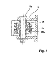
- FIG. 4 is also the connection of the scissors-type frame 10 to the vehicle 2, 3 recognizable, wherein the FIG. 5 an enlarged view of the detail V from FIG. 4 shows.
- This in FIG. 5 shown spherical bearing 11 comprises a bearing pin 11 a with a spherical collar 11 b on which a likewise spherically formed saddle 11 c rests, which is in communication with the scissor arm 15, 14.
- Such spherical bearings are state of the art, and so a detailed description of this bearing is unnecessary.
- a pivot joint 4a is provided in the form of a hinge or hinge strip, for example, in the region of the bottom 2a of the car body of the vehicle 2 is attached by a weld.
- Bridge side takes the pivot joint 4 a, the bottom plate 4 pivotally.
- the first cross member 50 extends.
- the Traverse is hereby arranged directly on the car body. It can also be additionally attached to the pivot joint 4a.
- This first cross member 50 is formed at right angles in the cross section in the manner of an "L".
- a likewise right-angled, L-shaped first carrier 51 is arranged on the bottom plate immediately in front of the pivot joint 4 a, which runs approximately parallel to the also right-angled cross member 50.
- the first carrier 51 serves to receive the spherical bearing 11.
- the first carrier 51 is supported relative to the cross member 50 via plastic buffer 55 both laterally and downwardly, as shown directly in the view of FIG Fig. 6 results.
- the car body of the vehicle 3 receives the second cross member 60.
- the second cross member 60 is formed in cross section as well as the first cross member substantially rectangular (L-shaped).
- This second cross member 60 is attached to the end wall of the vehicle 3, as is shown in the view of Fig. 7 results.
- a pivot joint 5a is provided, wherein the pivot joint 5a on the bridge side receives the bottom plate 5.
- the pivot joint 5a on the bridge side receives the bottom plate 5.
- the so-called overlap plate 7 on the pivot joint 5a is running at the opposite end in an alignment with the base plate 5, there is the so-called overlap plate 7 on the pivot joint 5a.
- the overlap plate 7 rests on the floor 3a of the car body of the vehicle 3.
- the joint also has the also in cross section rectangular, L-shaped second carrier 61, wherein the carrier 61, the spherical bearing 11 of the scissors frame 10 absorbs. Also, the carrier 61 is supported on plastic buffer 65 both laterally and vertically on the second cross member 60 from.
- a locking device 70 is provided ( Fig. 8 ).
- This locking device 70 comprises a finger 71, which is connected by a lever 72 with a rotatable square 73, wherein the lever is pivotally mounted on the finger 71.
- pivoting the lever 72 is pivoted in the clockwise direction by turning the square 73 of the fingers 71 from an opening 67, wherein the opening 67 is located in a vertical wall 68 on the horizontal leg of the second carrier.
- This wall 68 is arranged at the end of the carrier, so that the locking device 70 is fixed by the bearing block 69 for receiving the square 73 on the front side of the car body of the vehicle 3.
- the finger 71 is under the load of a spring 71 a, which ensures that the finger is always in the opening 67.
- connection of the bridge is taken in the form as they are in the FIGS. 6 on the one hand and 7 and 8 on the other hand, so only the finger 71 of the locking device 70 is released at the first end of the bridge to then pivot the entire bridge including the overlap plate 7 in the direction of the bellows roof, and thus free access to get to the bellows bottom, since, as stated, the centering members so in the present case, the two scissor racks are swung with.
Landscapes
- Engineering & Computer Science (AREA)
- Life Sciences & Earth Sciences (AREA)
- Wood Science & Technology (AREA)
- Mechanical Engineering (AREA)
- Bridges Or Land Bridges (AREA)
- Rehabilitation Tools (AREA)
- Mechanical Control Devices (AREA)
- Braking Elements And Transmission Devices (AREA)
Priority Applications (4)
| Application Number | Priority Date | Filing Date | Title |
|---|---|---|---|
| ES12005984.5T ES2524142T3 (es) | 2012-08-22 | 2012-08-22 | Pasarela o paso con un puente y un fuelle giratorio o rotativo en forma de túnel entre dos vehículos unidos por medio de una conexión articulada |
| PL12005984T PL2700553T3 (pl) | 2012-08-22 | 2012-08-22 | Przejście między dwoma połączonymi przegubowo pojazdami, wyposażone w pomost i osłonę wykonaną w kształcie tunelu otaczającą to przejście |
| EP12005984.5A EP2700553B1 (fr) | 2012-08-22 | 2012-08-22 | Passage avec un pont et un soufflet circonférentiel en forme de tunnel entre deux véhicules reliés par une liaison articulée |
| CN201310478349.1A CN103625488B (zh) | 2012-08-22 | 2013-08-22 | 过渡部的过桥 |
Applications Claiming Priority (1)
| Application Number | Priority Date | Filing Date | Title |
|---|---|---|---|
| EP12005984.5A EP2700553B1 (fr) | 2012-08-22 | 2012-08-22 | Passage avec un pont et un soufflet circonférentiel en forme de tunnel entre deux véhicules reliés par une liaison articulée |
Publications (2)
| Publication Number | Publication Date |
|---|---|
| EP2700553A1 true EP2700553A1 (fr) | 2014-02-26 |
| EP2700553B1 EP2700553B1 (fr) | 2014-10-15 |
Family
ID=46829601
Family Applications (1)
| Application Number | Title | Priority Date | Filing Date |
|---|---|---|---|
| EP12005984.5A Active EP2700553B1 (fr) | 2012-08-22 | 2012-08-22 | Passage avec un pont et un soufflet circonférentiel en forme de tunnel entre deux véhicules reliés par une liaison articulée |
Country Status (4)
| Country | Link |
|---|---|
| EP (1) | EP2700553B1 (fr) |
| CN (1) | CN103625488B (fr) |
| ES (1) | ES2524142T3 (fr) |
| PL (1) | PL2700553T3 (fr) |
Cited By (4)
| Publication number | Priority date | Publication date | Assignee | Title |
|---|---|---|---|---|
| CN108275166A (zh) * | 2018-03-19 | 2018-07-13 | 青岛欧特美交通装备有限公司 | 一种具有新型锁闭结构的渡板装置 |
| EP3530496A1 (fr) * | 2018-02-27 | 2019-08-28 | Narita Mfg., Ltd. | Dispositif d'expansion de panneaux |
| EP3939851A1 (fr) | 2020-07-16 | 2022-01-19 | Bombardier Transportation GmbH | Véhicule ferroviaire doté d'une paroi d'extrémité, d'une porte et de collecteur de repose-pieds |
| EP4563435A1 (fr) | 2023-12-01 | 2025-06-04 | Hübner GmbH & Co. KG | Passerelle de transition pour fournir une transition entre une première partie de véhicule et une seconde partie de véhicule d'un véhicule ainsi que véhicule équipé d'une telle passerelle de transition |
Families Citing this family (6)
| Publication number | Priority date | Publication date | Assignee | Title |
|---|---|---|---|---|
| KR101910998B1 (ko) * | 2016-12-09 | 2018-10-25 | 송한나 | 철도차량의 객차간 통로 바닥 연결 장치 |
| CN106985845B (zh) | 2016-12-30 | 2018-12-21 | 比亚迪股份有限公司 | 折棚主体、折棚总成和列车贯通道 |
| JP6467537B1 (ja) * | 2018-02-27 | 2019-02-13 | 株式会社成田製作所 | パネルの伸縮装置 |
| DE102018113349A1 (de) * | 2018-06-05 | 2019-12-05 | Bombardier Transportation Gmbh | Drehgelenk für ein Drehgestell eines Schienenfahrzeugs |
| EP3771605B1 (fr) * | 2019-08-02 | 2021-05-26 | Dellner Couplers AB | Passerelle pour connecter une première cabine d'un véhicule à plusieurs cabines à une seconde cabine |
| CN113320557B (zh) * | 2020-02-28 | 2022-11-11 | 比亚迪股份有限公司 | 用于轨道车辆的贯通道和具有其的轨道车辆 |
Citations (10)
| Publication number | Priority date | Publication date | Assignee | Title |
|---|---|---|---|---|
| DE966430C (de) * | 1954-04-21 | 1957-08-14 | Waggonfabrik Jos Rathgeber A G | UEbergangsbruecke fuer gekoppelte Fahrzeuge, insbesondere Eisenbahnwaggons |
| EP0331121A2 (fr) | 1988-03-02 | 1989-09-06 | HÜBNER Gummi- und Kunststoff GmbH | Elément de passerelle d'intercommunication séparable pour véhicules |
| EP0669243B1 (fr) | 1994-02-25 | 1997-08-06 | HÜBNER Gummi- und Kunststoff GmbH | Eléments d'une passerelle d'intercommunication mobile en diagonale entre deux véhicules |
| EP0722873B1 (fr) | 1995-01-19 | 1998-08-05 | HÜBNER Gummi- und Kunststoff GmbH | Passerelle |
| US6443070B1 (en) | 1999-11-26 | 2002-09-03 | Faiveley Transport | Floor for circulating between two vehicles |
| EP0958981B1 (fr) | 1998-05-16 | 2002-09-11 | HÜBNER Gummi- und Kunststoff GmbH | Deux véhicules ou parties de véhicule reliés de manière articulée entre-eux, notamment entre deux autorails reliés de manière articulée, avec une inter-circulation. |
| JP2007022213A (ja) * | 2005-07-13 | 2007-02-01 | Kinki Sharyo Co Ltd | 鉄道車両の渡り板装置 |
| EP1564101B1 (fr) | 2004-02-10 | 2007-03-28 | HÜBNER GmbH | Passerelle pour une intercirculation avec un soufflet, pour le passage entre des véhicules ferroviaires articulés. |
| EP2157006A1 (fr) | 2008-08-22 | 2010-02-24 | HÜBNER GmbH | Passerelle pour un passage d'intercirculation entre deux véhicules articulés, par exemple d'un tramway |
| EP2457796A1 (fr) | 2010-11-26 | 2012-05-30 | Hübner GmbH | Pont d'un passage entre deux véhicules reliés de manière articulée |
Family Cites Families (2)
| Publication number | Priority date | Publication date | Assignee | Title |
|---|---|---|---|---|
| CH687379A5 (de) * | 1993-09-03 | 1996-11-29 | Sig Schweiz Industrieges | Uebergangseinrichtung zwischen zwei gekuppelten Fahrzeugen. |
| DE10028234A1 (de) * | 2000-06-07 | 2001-12-20 | Guido Kuebler Gmbh | Vorrichtung zur lösbaren Verbindung von zwei in Reihe angeordneten Fahrzeugelementen eines Fahrzeugs und deren Verwendung |
-
2012
- 2012-08-22 EP EP12005984.5A patent/EP2700553B1/fr active Active
- 2012-08-22 ES ES12005984.5T patent/ES2524142T3/es active Active
- 2012-08-22 PL PL12005984T patent/PL2700553T3/pl unknown
-
2013
- 2013-08-22 CN CN201310478349.1A patent/CN103625488B/zh active Active
Patent Citations (10)
| Publication number | Priority date | Publication date | Assignee | Title |
|---|---|---|---|---|
| DE966430C (de) * | 1954-04-21 | 1957-08-14 | Waggonfabrik Jos Rathgeber A G | UEbergangsbruecke fuer gekoppelte Fahrzeuge, insbesondere Eisenbahnwaggons |
| EP0331121A2 (fr) | 1988-03-02 | 1989-09-06 | HÜBNER Gummi- und Kunststoff GmbH | Elément de passerelle d'intercommunication séparable pour véhicules |
| EP0669243B1 (fr) | 1994-02-25 | 1997-08-06 | HÜBNER Gummi- und Kunststoff GmbH | Eléments d'une passerelle d'intercommunication mobile en diagonale entre deux véhicules |
| EP0722873B1 (fr) | 1995-01-19 | 1998-08-05 | HÜBNER Gummi- und Kunststoff GmbH | Passerelle |
| EP0958981B1 (fr) | 1998-05-16 | 2002-09-11 | HÜBNER Gummi- und Kunststoff GmbH | Deux véhicules ou parties de véhicule reliés de manière articulée entre-eux, notamment entre deux autorails reliés de manière articulée, avec une inter-circulation. |
| US6443070B1 (en) | 1999-11-26 | 2002-09-03 | Faiveley Transport | Floor for circulating between two vehicles |
| EP1564101B1 (fr) | 2004-02-10 | 2007-03-28 | HÜBNER GmbH | Passerelle pour une intercirculation avec un soufflet, pour le passage entre des véhicules ferroviaires articulés. |
| JP2007022213A (ja) * | 2005-07-13 | 2007-02-01 | Kinki Sharyo Co Ltd | 鉄道車両の渡り板装置 |
| EP2157006A1 (fr) | 2008-08-22 | 2010-02-24 | HÜBNER GmbH | Passerelle pour un passage d'intercirculation entre deux véhicules articulés, par exemple d'un tramway |
| EP2457796A1 (fr) | 2010-11-26 | 2012-05-30 | Hübner GmbH | Pont d'un passage entre deux véhicules reliés de manière articulée |
Cited By (8)
| Publication number | Priority date | Publication date | Assignee | Title |
|---|---|---|---|---|
| EP3530496A1 (fr) * | 2018-02-27 | 2019-08-28 | Narita Mfg., Ltd. | Dispositif d'expansion de panneaux |
| US10414415B1 (en) | 2018-02-27 | 2019-09-17 | Narita Mfg., Ltd. | Expansion device of panels |
| CN108275166A (zh) * | 2018-03-19 | 2018-07-13 | 青岛欧特美交通装备有限公司 | 一种具有新型锁闭结构的渡板装置 |
| EP3939851A1 (fr) | 2020-07-16 | 2022-01-19 | Bombardier Transportation GmbH | Véhicule ferroviaire doté d'une paroi d'extrémité, d'une porte et de collecteur de repose-pieds |
| GB2598541A (en) * | 2020-07-16 | 2022-03-09 | Bombardier Transp Gmbh | Rail vehicle provided with an end wall, a doorway and footplate catchers |
| GB2598541B (en) * | 2020-07-16 | 2022-12-07 | Bombardier Transp Gmbh | Rail vehicle provided with an end wall, a doorway and footplate catchers |
| US12179810B2 (en) | 2020-07-16 | 2024-12-31 | Bombardier Transportation Gmbh | Rail vehicle provided with an end wall, a doorway, and footplate catchers |
| EP4563435A1 (fr) | 2023-12-01 | 2025-06-04 | Hübner GmbH & Co. KG | Passerelle de transition pour fournir une transition entre une première partie de véhicule et une seconde partie de véhicule d'un véhicule ainsi que véhicule équipé d'une telle passerelle de transition |
Also Published As
| Publication number | Publication date |
|---|---|
| EP2700553B1 (fr) | 2014-10-15 |
| ES2524142T3 (es) | 2014-12-04 |
| PL2700553T3 (pl) | 2015-02-27 |
| CN103625488B (zh) | 2017-02-22 |
| CN103625488A (zh) | 2014-03-12 |
Similar Documents
| Publication | Publication Date | Title |
|---|---|---|
| EP2700553B1 (fr) | Passage avec un pont et un soufflet circonférentiel en forme de tunnel entre deux véhicules reliés par une liaison articulée | |
| EP2457796B1 (fr) | Pont d'un passage entre deux véhicules reliés de manière articulée | |
| EP2500230B1 (fr) | Pont d'un passage entre deux éléments de véhicule reliés de manière articulée | |
| EP3549900B1 (fr) | Élévateur pour véhicules automobiles | |
| EP1789299B1 (fr) | Vehicule de maintenance | |
| EP3287305B1 (fr) | Structure articulee et passage comprenant une structure articulee | |
| DE4227126A1 (de) | Gelenkverbindung zwischen zwei gelenkig miteinander verbundenen Fahrzeugen | |
| EP2161176B1 (fr) | Pont d'un passage doté d'un soufflet entre deux parties de véhicule reliées ensemble de manière articulée, par exemple d'un tramway | |
| EP2676824B1 (fr) | Structure pour le transports de biens | |
| DE2705979C3 (de) | Lastwagen mit in seiner Längsrichtung verschiebbarem Ladebodenabschnitt | |
| EP1712443B1 (fr) | Véhicule articulé à unités multiples, notamment véhicule ferroviaire. | |
| DE102007027592A1 (de) | Fahrzeug mit gelenkig verbundenen Wagenkästen | |
| DE102013218547B3 (de) | Übergangsplattform mit Verwindungszonen, Fahrzeuggelenksystem und Schienenfahrzeug | |
| DE69200515T2 (de) | Eisenbahnwagen zum Tragen von verriegelbaren Ladungssätteln und Ladungssattel für ein solchen Wagen. | |
| DE1287104B (de) | Zug- und Stossvorrichtungen fuer Eisenbahnwagen | |
| EP0983931A2 (fr) | Connexion entre deux parties de véhicule articulé | |
| DE102014220775B4 (de) | Schienenfahrzeug in Aufliegerausführung | |
| EP2594450B1 (fr) | Moitié de passerelle entre deux véhicules d'un véhicule sur rail reliés entre eux de manière articulée | |
| EP2236382B1 (fr) | Dispositif d'intercirculation avec soufflet déformable, pour vehicles ferroviaires | |
| EP0306015A1 (fr) | Système de guidage pour le guidage forcé d'éléments mobiles l'un par rapport à l'autre | |
| DE3839716A1 (de) | Stirnseite eines eisenbahnreisezugwagens | |
| DE19740388C2 (de) | Traggestell für Förderer, insbesondere für Bandförderer | |
| DE3004218A1 (de) | Hoehenverstellbare sattelkupplung | |
| DE102015214747A1 (de) | Übergangseinrichtung für Schienenfahrzeuge | |
| EP3265359B1 (fr) | Articulation tournante pour la liaison par articulation tournante de véhicules ferroviaires |
Legal Events
| Date | Code | Title | Description |
|---|---|---|---|
| PUAI | Public reference made under article 153(3) epc to a published international application that has entered the european phase |
Free format text: ORIGINAL CODE: 0009012 |
|
| 17P | Request for examination filed |
Effective date: 20130305 |
|
| AK | Designated contracting states |
Kind code of ref document: A1 Designated state(s): AL AT BE BG CH CY CZ DE DK EE ES FI FR GB GR HR HU IE IS IT LI LT LU LV MC MK MT NL NO PL PT RO RS SE SI SK SM TR |
|
| AX | Request for extension of the european patent |
Extension state: BA ME |
|
| GRAP | Despatch of communication of intention to grant a patent |
Free format text: ORIGINAL CODE: EPIDOSNIGR1 |
|
| INTG | Intention to grant announced |
Effective date: 20140516 |
|
| RAP1 | Party data changed (applicant data changed or rights of an application transferred) |
Owner name: HUEBNER GMBH & CO. KG |
|
| GRAS | Grant fee paid |
Free format text: ORIGINAL CODE: EPIDOSNIGR3 |
|
| GRAA | (expected) grant |
Free format text: ORIGINAL CODE: 0009210 |
|
| AK | Designated contracting states |
Kind code of ref document: B1 Designated state(s): AL AT BE BG CH CY CZ DE DK EE ES FI FR GB GR HR HU IE IS IT LI LT LU LV MC MK MT NL NO PL PT RO RS SE SI SK SM TR |
|
| REG | Reference to a national code |
Ref country code: GB Ref legal event code: FG4D Free format text: NOT ENGLISH Ref country code: CH Ref legal event code: EP |
|
| REG | Reference to a national code |
Ref country code: IE Ref legal event code: FG4D Free format text: LANGUAGE OF EP DOCUMENT: GERMAN |
|
| REG | Reference to a national code |
Ref country code: AT Ref legal event code: REF Ref document number: 691496 Country of ref document: AT Kind code of ref document: T Effective date: 20141115 |
|
| REG | Reference to a national code |
Ref country code: DE Ref legal event code: R096 Ref document number: 502012001408 Country of ref document: DE Effective date: 20141127 |
|
| REG | Reference to a national code |
Ref country code: ES Ref legal event code: FG2A Ref document number: 2524142 Country of ref document: ES Kind code of ref document: T3 Effective date: 20141204 |
|
| REG | Reference to a national code |
Ref country code: PL Ref legal event code: T3 |
|
| REG | Reference to a national code |
Ref country code: NL Ref legal event code: VDEP Effective date: 20141015 |
|
| REG | Reference to a national code |
Ref country code: LT Ref legal event code: MG4D |
|
| PG25 | Lapsed in a contracting state [announced via postgrant information from national office to epo] |
Ref country code: NL Free format text: LAPSE BECAUSE OF FAILURE TO SUBMIT A TRANSLATION OF THE DESCRIPTION OR TO PAY THE FEE WITHIN THE PRESCRIBED TIME-LIMIT Effective date: 20141015 |
|
| PG25 | Lapsed in a contracting state [announced via postgrant information from national office to epo] |
Ref country code: PT Free format text: LAPSE BECAUSE OF FAILURE TO SUBMIT A TRANSLATION OF THE DESCRIPTION OR TO PAY THE FEE WITHIN THE PRESCRIBED TIME-LIMIT Effective date: 20150216 Ref country code: LT Free format text: LAPSE BECAUSE OF FAILURE TO SUBMIT A TRANSLATION OF THE DESCRIPTION OR TO PAY THE FEE WITHIN THE PRESCRIBED TIME-LIMIT Effective date: 20141015 Ref country code: NO Free format text: LAPSE BECAUSE OF FAILURE TO SUBMIT A TRANSLATION OF THE DESCRIPTION OR TO PAY THE FEE WITHIN THE PRESCRIBED TIME-LIMIT Effective date: 20150115 Ref country code: IS Free format text: LAPSE BECAUSE OF FAILURE TO SUBMIT A TRANSLATION OF THE DESCRIPTION OR TO PAY THE FEE WITHIN THE PRESCRIBED TIME-LIMIT Effective date: 20150215 Ref country code: FI Free format text: LAPSE BECAUSE OF FAILURE TO SUBMIT A TRANSLATION OF THE DESCRIPTION OR TO PAY THE FEE WITHIN THE PRESCRIBED TIME-LIMIT Effective date: 20141015 |
|
| PG25 | Lapsed in a contracting state [announced via postgrant information from national office to epo] |
Ref country code: LV Free format text: LAPSE BECAUSE OF FAILURE TO SUBMIT A TRANSLATION OF THE DESCRIPTION OR TO PAY THE FEE WITHIN THE PRESCRIBED TIME-LIMIT Effective date: 20141015 Ref country code: HR Free format text: LAPSE BECAUSE OF FAILURE TO SUBMIT A TRANSLATION OF THE DESCRIPTION OR TO PAY THE FEE WITHIN THE PRESCRIBED TIME-LIMIT Effective date: 20141015 Ref country code: SE Free format text: LAPSE BECAUSE OF FAILURE TO SUBMIT A TRANSLATION OF THE DESCRIPTION OR TO PAY THE FEE WITHIN THE PRESCRIBED TIME-LIMIT Effective date: 20141015 Ref country code: CY Free format text: LAPSE BECAUSE OF FAILURE TO SUBMIT A TRANSLATION OF THE DESCRIPTION OR TO PAY THE FEE WITHIN THE PRESCRIBED TIME-LIMIT Effective date: 20141015 Ref country code: GR Free format text: LAPSE BECAUSE OF FAILURE TO SUBMIT A TRANSLATION OF THE DESCRIPTION OR TO PAY THE FEE WITHIN THE PRESCRIBED TIME-LIMIT Effective date: 20150116 Ref country code: RS Free format text: LAPSE BECAUSE OF FAILURE TO SUBMIT A TRANSLATION OF THE DESCRIPTION OR TO PAY THE FEE WITHIN THE PRESCRIBED TIME-LIMIT Effective date: 20141015 |
|
| REG | Reference to a national code |
Ref country code: DE Ref legal event code: R097 Ref document number: 502012001408 Country of ref document: DE |
|
| PG25 | Lapsed in a contracting state [announced via postgrant information from national office to epo] |
Ref country code: EE Free format text: LAPSE BECAUSE OF FAILURE TO SUBMIT A TRANSLATION OF THE DESCRIPTION OR TO PAY THE FEE WITHIN THE PRESCRIBED TIME-LIMIT Effective date: 20141015 Ref country code: CZ Free format text: LAPSE BECAUSE OF FAILURE TO SUBMIT A TRANSLATION OF THE DESCRIPTION OR TO PAY THE FEE WITHIN THE PRESCRIBED TIME-LIMIT Effective date: 20141015 Ref country code: DK Free format text: LAPSE BECAUSE OF FAILURE TO SUBMIT A TRANSLATION OF THE DESCRIPTION OR TO PAY THE FEE WITHIN THE PRESCRIBED TIME-LIMIT Effective date: 20141015 Ref country code: SK Free format text: LAPSE BECAUSE OF FAILURE TO SUBMIT A TRANSLATION OF THE DESCRIPTION OR TO PAY THE FEE WITHIN THE PRESCRIBED TIME-LIMIT Effective date: 20141015 Ref country code: RO Free format text: LAPSE BECAUSE OF FAILURE TO SUBMIT A TRANSLATION OF THE DESCRIPTION OR TO PAY THE FEE WITHIN THE PRESCRIBED TIME-LIMIT Effective date: 20141015 |
|
| REG | Reference to a national code |
Ref country code: FR Ref legal event code: PLFP Year of fee payment: 4 |
|
| PLBE | No opposition filed within time limit |
Free format text: ORIGINAL CODE: 0009261 |
|
| STAA | Information on the status of an ep patent application or granted ep patent |
Free format text: STATUS: NO OPPOSITION FILED WITHIN TIME LIMIT |
|
| 26N | No opposition filed |
Effective date: 20150716 |
|
| PG25 | Lapsed in a contracting state [announced via postgrant information from national office to epo] |
Ref country code: SI Free format text: LAPSE BECAUSE OF FAILURE TO SUBMIT A TRANSLATION OF THE DESCRIPTION OR TO PAY THE FEE WITHIN THE PRESCRIBED TIME-LIMIT Effective date: 20141015 |
|
| PG25 | Lapsed in a contracting state [announced via postgrant information from national office to epo] |
Ref country code: LU Free format text: LAPSE BECAUSE OF FAILURE TO SUBMIT A TRANSLATION OF THE DESCRIPTION OR TO PAY THE FEE WITHIN THE PRESCRIBED TIME-LIMIT Effective date: 20150822 Ref country code: MC Free format text: LAPSE BECAUSE OF FAILURE TO SUBMIT A TRANSLATION OF THE DESCRIPTION OR TO PAY THE FEE WITHIN THE PRESCRIBED TIME-LIMIT Effective date: 20141015 |
|
| REG | Reference to a national code |
Ref country code: CH Ref legal event code: PL |
|
| PG25 | Lapsed in a contracting state [announced via postgrant information from national office to epo] |
Ref country code: CH Free format text: LAPSE BECAUSE OF NON-PAYMENT OF DUE FEES Effective date: 20150831 Ref country code: LI Free format text: LAPSE BECAUSE OF NON-PAYMENT OF DUE FEES Effective date: 20150831 |
|
| REG | Reference to a national code |
Ref country code: IE Ref legal event code: MM4A |
|
| PG25 | Lapsed in a contracting state [announced via postgrant information from national office to epo] |
Ref country code: IE Free format text: LAPSE BECAUSE OF NON-PAYMENT OF DUE FEES Effective date: 20150822 |
|
| REG | Reference to a national code |
Ref country code: FR Ref legal event code: PLFP Year of fee payment: 5 |
|
| REG | Reference to a national code |
Ref country code: DE Ref legal event code: R083 Ref document number: 502012001408 Country of ref document: DE |
|
| PG25 | Lapsed in a contracting state [announced via postgrant information from national office to epo] |
Ref country code: MT Free format text: LAPSE BECAUSE OF FAILURE TO SUBMIT A TRANSLATION OF THE DESCRIPTION OR TO PAY THE FEE WITHIN THE PRESCRIBED TIME-LIMIT Effective date: 20141015 |
|
| PG25 | Lapsed in a contracting state [announced via postgrant information from national office to epo] |
Ref country code: BG Free format text: LAPSE BECAUSE OF FAILURE TO SUBMIT A TRANSLATION OF THE DESCRIPTION OR TO PAY THE FEE WITHIN THE PRESCRIBED TIME-LIMIT Effective date: 20141015 Ref country code: HU Free format text: LAPSE BECAUSE OF FAILURE TO SUBMIT A TRANSLATION OF THE DESCRIPTION OR TO PAY THE FEE WITHIN THE PRESCRIBED TIME-LIMIT; INVALID AB INITIO Effective date: 20120822 Ref country code: SM Free format text: LAPSE BECAUSE OF FAILURE TO SUBMIT A TRANSLATION OF THE DESCRIPTION OR TO PAY THE FEE WITHIN THE PRESCRIBED TIME-LIMIT Effective date: 20141015 |
|
| PG25 | Lapsed in a contracting state [announced via postgrant information from national office to epo] |
Ref country code: BE Free format text: LAPSE BECAUSE OF NON-PAYMENT OF DUE FEES Effective date: 20150831 |
|
| REG | Reference to a national code |
Ref country code: FR Ref legal event code: PLFP Year of fee payment: 6 |
|
| PG25 | Lapsed in a contracting state [announced via postgrant information from national office to epo] |
Ref country code: MK Free format text: LAPSE BECAUSE OF FAILURE TO SUBMIT A TRANSLATION OF THE DESCRIPTION OR TO PAY THE FEE WITHIN THE PRESCRIBED TIME-LIMIT Effective date: 20141015 Ref country code: TR Free format text: LAPSE BECAUSE OF FAILURE TO SUBMIT A TRANSLATION OF THE DESCRIPTION OR TO PAY THE FEE WITHIN THE PRESCRIBED TIME-LIMIT Effective date: 20141015 |
|
| REG | Reference to a national code |
Ref country code: FR Ref legal event code: PLFP Year of fee payment: 7 |
|
| PG25 | Lapsed in a contracting state [announced via postgrant information from national office to epo] |
Ref country code: AL Free format text: LAPSE BECAUSE OF FAILURE TO SUBMIT A TRANSLATION OF THE DESCRIPTION OR TO PAY THE FEE WITHIN THE PRESCRIBED TIME-LIMIT Effective date: 20141015 |
|
| P01 | Opt-out of the competence of the unified patent court (upc) registered |
Effective date: 20230911 |
|
| PGFP | Annual fee paid to national office [announced via postgrant information from national office to epo] |
Ref country code: ES Payment date: 20250917 Year of fee payment: 14 |
|
| PGFP | Annual fee paid to national office [announced via postgrant information from national office to epo] |
Ref country code: DE Payment date: 20250819 Year of fee payment: 14 |
|
| PGFP | Annual fee paid to national office [announced via postgrant information from national office to epo] |
Ref country code: PL Payment date: 20250814 Year of fee payment: 14 Ref country code: IT Payment date: 20250829 Year of fee payment: 14 |
|
| PGFP | Annual fee paid to national office [announced via postgrant information from national office to epo] |
Ref country code: GB Payment date: 20250822 Year of fee payment: 14 |
|
| PGFP | Annual fee paid to national office [announced via postgrant information from national office to epo] |
Ref country code: FR Payment date: 20250821 Year of fee payment: 14 Ref country code: AT Payment date: 20250819 Year of fee payment: 14 |