EP4563435A1 - Passerelle de transition pour fournir une transition entre une première partie de véhicule et une seconde partie de véhicule d'un véhicule ainsi que véhicule équipé d'une telle passerelle de transition - Google Patents
Passerelle de transition pour fournir une transition entre une première partie de véhicule et une seconde partie de véhicule d'un véhicule ainsi que véhicule équipé d'une telle passerelle de transition Download PDFInfo
- Publication number
- EP4563435A1 EP4563435A1 EP23213686.1A EP23213686A EP4563435A1 EP 4563435 A1 EP4563435 A1 EP 4563435A1 EP 23213686 A EP23213686 A EP 23213686A EP 4563435 A1 EP4563435 A1 EP 4563435A1
- Authority
- EP
- European Patent Office
- Prior art keywords
- end wall
- plate
- centering element
- transition bridge
- transition
- Prior art date
- Legal status (The legal status is an assumption and is not a legal conclusion. Google has not performed a legal analysis and makes no representation as to the accuracy of the status listed.)
- Granted
Links
Images




Classifications
-
- B—PERFORMING OPERATIONS; TRANSPORTING
- B61—RAILWAYS
- B61D—BODY DETAILS OR KINDS OF RAILWAY VEHICLES
- B61D17/00—Construction details of vehicle bodies
- B61D17/04—Construction details of vehicle bodies with bodies of metal; with composite, e.g. metal and wood body structures
- B61D17/20—Communication passages between coaches; Adaptation of coach ends therefor
Definitions
- the present invention relates to a transition bridge for providing a transition between a first vehicle part and a second vehicle part of a vehicle. Furthermore, the present invention relates to a vehicle having such a transition bridge.
- transition bridges can be designed in the manner of a combination bridge, also called a "combination bridge" for short, and serve to provide a safe transition for passengers, particularly of a rail vehicle or a bus, between two adjacent vehicle sections.
- the transition bridges have a centering element, on which a first floor plate, a second floor plate, and a step plate are usually movably mounted in order to compensate for the relative movements occurring between the first vehicle section and the second vehicle section during operation of the vehicle.
- the first floor plate adjoins the first vehicle section and the second floor plate adjoins the second vehicle section, while the step plate is arranged between the two floor plates and slightly overlaps them. Further information on such transition bridges can be found in the EP 0 331 121 A2 , the EP 0 669 243 A1 , the EP 0 958 981 A1 and the EP 0 722 873 A1 be taken.
- the bridges are primarily crossed by passengers to move from one section of the vehicle to the adjacent section. Passengers' dwell time is correspondingly short. However, on subways and metros, in particular, large numbers of passengers congregate on the bridges, especially during peak hours. The load on the bridges is correspondingly high, and they must be dimensioned accordingly, which, among other things, increases their weight.
- the transition bridges are surrounded by bellows to enable a continuous, closed transition between two adjacent vehicle sections. Electrical cables and other supply lines, for example for air conditioning, often run through the bellows.
- the vehicle sections are equipped with Coupling devices are connected to each other.
- the aforementioned components often run beneath the transition bridges. For maintenance purposes, it is therefore desirable to be able to remove the transition bridges quickly and easily in order to provide access to the aforementioned components.
- EP 2 457 796 A1 The combination bridge shown is generally suitable for use in underground railways and metros, but the dismantling effort during maintenance is relatively high.
- EP 2 700 553 A1 proposes a transition bridge that can be pivoted around a pivot axis. In the event of maintenance, this can be rotated around the pivot axis with relatively little effort, thus providing access to the elements arranged below the transition bridge in relation to the intended arrangement.
- the pivot axis runs between the vehicle part and the base plate, whereby the force flow through the centering element also leads through the base plate and only then into the vehicle part.
- EP 4 035 911 A1 This is the case with the combination bridge disclosed.
- the load-bearing capacity of these transition bridges is limited, particularly due to the force flow through the relatively thin base plate, which is why they are only partially suitable for use in underground railways and metros.
- the object of one embodiment of the present invention is to propose a transition bridge for a transition or a transition between a first vehicle part and a second vehicle part of a vehicle, with which it is possible to provide a remedy for the above-mentioned disadvantages.
- the transition bridge should, on the one hand, enable quick and easy access to components arranged between two adjacent vehicle parts and, on the other hand, also be usable for high loads such as those encountered in underground railways and metros.
- one embodiment of the present invention is based on the object of creating a vehicle that can be equipped with such a transition bridge.
- the centering element can comprise components to provide the rotatable connection of the centering element to the axis of rotation, these components generally do not have any additional functions.
- the components are not base plates or the like.
- the axis of rotation can be formed, for example, by a rod or a bolt.
- the force flow therefore runs directly between the first end wall and the centering element, which is why this transition bridge is suitable for high loads.
- the first base plate which is to be understood as the proximal base plate from the first end wall, is not directly connected to the first end wall, but, as explained, only indirectly to the centering element and is therefore not part of the force flow.
- the rotation only takes place around a common axis of rotation, so that there is no relative movement between the first base plate, the second base plate, the tread plate and the centering element when rotating.
- the EP 2 457 796 A1 In the combination bridge shown, the first floor plate, the second floor plate, the step plate, and the centering element can rotate by a maximum of 20°, so that no usable access to the components arranged between two adjacent vehicle parts can be provided. In contrast, with the combination bridge according to the invention, a fundamentally unlimited rotation is possible.
- first end and second end can be interpreted broadly, so that, for example, the axis of rotation could also pass through the center of the centering element a little further towards the center.
- the transition bridge can have a locking device with which the centering element at its second end and/or the second base plate can be detachably connected to the second end wall.
- the locking device can ensure that no excessively large gap forms between the second base plate and the second end wall, which could pose a danger to the passengers of the vehicle in question.
- the size of the gap can be defined with the locking device such that relative movements that occur between the first vehicle part and the second vehicle part during operation of the vehicle are permitted without significant friction and the associated abrasion. Furthermore, the noise generated during this process can be avoided.
- the first vehicle section and the second vehicle section are often manufactured by different manufacturers than the gangway. Consequently, the first end wall and the second end wall often cannot be adapted to the structural details of the gangway.
- the first end strip and the second end strip can be designed by the gangway manufacturer in a way that makes sense for the function and operation of the gangway.
- the first end strip and the second end strip can be adapted to the structural conditions of the respective first end wall and second end wall with comparatively little effort.
- the first end strip and the second end strip act as a type of adapter between the gangway and the first vehicle section and the second vehicle section. Retrofitting vehicles that have already been in operation for some time is also possible with little effort using the end strips.
- the rotation axis is strictly speaking no longer attached to the first end wall, but rather to the first end strip.
- the first end strip can be attached to the first end wall in such a way that the force flow continues to be largely direct from the centering element to the first end wall, without the first base plate or other components being involved in the force flow.
- the centering element interacts with the end wall using the first end strip.
- the second end wall and/or the second end strip can have fastening sections into which counter-fastening sections of the transition bridge and in particular the second floor plate and/or the centering element can be inserted.
- the fastening sections and the counter-fastening sections can be part of the locking device, which can be easily adapted to the structural conditions of the first vehicle part and the second vehicle part.
- the counter-fastening sections are rotatably mounted on the transition bridge and in particular on the second base plate.
- the counter-fastening sections interact either with the second end wall and/or with the second end strip, in any case with the second vehicle part, while the transition bridge as such is mounted on the first vehicle part.
- the rotational position of the counter-fastening sections relative to the second end wall, the second end strip and/or the fastening sections would also change, as a result of which the counter-fastening sections could be exposed to increased loads or could move out of the fastening sections.
- the rotatable mounting of the counter-fastening sections can follow the rotational movements of the first vehicle part and the second vehicle part relative to one another, as a result of which the above-mentioned increased loads and movement out of the fastening sections can be avoided.
- the rotatable mounting of the counter-fastening sections can be realized, for example, by means of a bearing axle which is fastened to the second floor plate.
- the centering element In the first rotational position, the centering element, in particular together with the first floor plate, the second floor plate and the step plate, provides the transition between the first vehicle part and the second vehicle part. In order to transfer the centering element from the first rotational position to the second rotational position, the centering element is rotated by approximately 90°. In the second rotational position, access to components of the vehicle arranged below the transition bridge, in particular to the coupling device, is possible, in particular for inspection and maintenance purposes. In the second rotational position, the connection of the centering element and/or the second floor plate to the second bulkhead is removed, whereby the first vehicle part can be separated from the second vehicle part.
- the transition bridge in this embodiment has holding means.
- the holding means can be arranged on the first end wall and in the second rotational position interact in particular with the first base plate, the second base plate and/or the tread plate. Due to the connection of the first base plate, the second base plate and the tread plate to the centering element, the latter is also fixed in the second rotational position.
- the centering element interacts at least indirectly with the holding means.
- a direct connection between the holding means and the centering element would also be conceivable.
- the decisive factor is that the transition bridge can be fixed in the second rotational position with the holding means.
- the first rotational position can be determined, for example, by means of an alignment element which is fastened to the second base plate and rests, for example, on a projection of the second end wall or the second end strip.
- the parting plane between the first sub-unit and the second sub-unit, at which the floor plates and the step plates abut one another, runs parallel to the main direction of travel of the vehicle and, when the vehicle is traveling straight ahead or is aligned straight, perpendicular to the first end wall and the second end wall.
- the first subunit and the second subunit can be identical or largely identical, which is advantageous from a manufacturing perspective.
- the subunits are shorter and lighter, which facilitates assembly and transport, particularly to the assembly site. Due in particular to their lower weight, the first subunit and the second subunit can be moved between the first rotational position and the second rotational position with less effort. Furthermore, for maintenance and inspection purposes, it may be sufficient to move only one of the subunits into the second rotational position. The transition between the first vehicle part and the second vehicle part is still possible with the other subunit, albeit with restrictions. This keeps disruptions during maintenance or inspection to a minimum.
- Both the first subunit and the second subunit can be rotatably connected to a common axis of rotation, wherein the common axis of rotation can be arranged on the first end wall or the second end wall.
- the first subunit and the second subunit are to be identical or largely identical, it is advisable to attach the first subunit to the first end wall and the second One end wall can be arranged on the second end wall, or vice versa.
- each of the subunits has its own axis of rotation, to which they are rotatably connected.
- the tread plate separation plane between the first tread plate and the second tread plate can be offset from the floor plate separation planes between the primary first floor plate and the secondary second floor plate, or between the primary second floor plate and the secondary first floor plate. This creates overlapping areas between the first subunit and the second subunit, allowing loads to be transferred between the first subunit and the second subunit. Consequently, the first subunit and the second subunit are loaded more evenly than if the tread plate separation plane and the floor plate separation planes were aligned.
- the first locking device and the second locking device can ensure that no excessively large gap forms between the primary second floor panel and the second bulkhead or between the secondary second floor panel and the first bulkhead, which could pose a danger to the passengers of the vehicle in question.
- the size of the gap can be defined with the first locking device or the second locking device in such a way that relative movements that occur in the During vehicle operation, friction between the first and second vehicle parts can be permitted without significant friction and the associated abrasion. Furthermore, the resulting noise can be avoided.
- the transition bridge may comprise a connecting body or a connecting structure with which the first tread plate and the second tread plate can be detachably connected to one another in a force-transmitting manner.
- the connecting structure can be designed, for example, in the manner of a tongue and groove connection.
- a connecting body can, for example, be a rod arranged on the first tread plate, which can engage in a complementary recess on the second tread plate. In this way, loads can be transferred between the two sub-units so that they are loaded more evenly overall.
- it can be prevented that one sub-unit deforms severely under particularly high loads, while the other sub-unit deforms less severely due to a lower load. Steps caused by the different degrees of deformation, over which passengers could trip, are avoided.
- the connecting body interacts with the first tread plate and the second tread plate.
- this does not preclude the alternative or cumulative provision of connecting bodies that interact with the floor plates to transmit forces.
- the technical effects achieved here are essentially the same as those provided with a connecting body that interacts with the tread plates.
- the connecting body can have projections and/or recesses with which the first tread plate and the second tread plate can be brought into positive engagement by means of a movement along the plate plane.
- the connecting body can, for example, have an H-shaped cross section.
- the first tread plate can be inserted into one of the recesses and then screwed to the connecting body.
- the second tread plate can be inserted into the second recess by means of a movement along the plate plane when the first subunit and the second subunit are in the first rotational position.
- the second tread plate When the second tread plate is to be set in the second rotational position, the second tread plate first moved out of the second recess and then placed in the second rotational position.
- the connecting body can have one or more locking hooks that engage with locking sections of the second tread plate.
- the locking hooks also serve to transmit forces and torques between the subunits.
- the connecting body is divided into two parts. This makes it possible to construct the first subsection and the second subsection of the transition bridge with identical or largely identical construction, which is advantageous in terms of manufacturing and simplifies assembly.
- the transition bridge can have a fixing device with which the first tread plate and the second tread plate can be releasably connected to one another such that the position of the first tread plate relative to the second tread plate can be fixed.
- the first centering element and the second centering element are designed such that they allow movement of the floor plates and the tread plates along the plate plane.
- the connecting body can be designed such that a force-transmitting connection is provided between the first tread plate and the second tread plate with a movement parallel to the plate plane.
- this also means that the force-transmitting connection between the first tread plate and the second tread plate can be canceled as a result of loads that occur during operation of the vehicle. Because a fixing device is provided in this embodiment, such movement of the first tread plate and the second tread plate parallel to the plate plane can be avoided. As a result, the force-transmitting connection between the first tread plate and the second tread plate is also prevented from being accidentally broken.
- the first and second fastening sections as well as the first and second counter-fastening sections can be part of the first locking device and second locking device, respectively, which can be easily adapted to the structural conditions of the first vehicle part and the second vehicle part.
- first counter-fastening sections can be rotatably mounted on the primary second base plate and the second counter-fastening sections can be rotatably mounted on the secondary second base plate.
- One embodiment of the invention relates to a vehicle having a first vehicle part and a second vehicle part, wherein the first vehicle part and the second vehicle part are articulated or connected to one another by means of a coupling device and the vehicle has a transition bridge according to one of the previous embodiments.
- a force flow can be provided directly between the first end wall and the centering element, depending on the design, including an end strip, without the force flow passing through floor slabs or similar structural elements.
- the vehicle is suitable for high loads in the transition, which are particularly common in underground railways and metros.
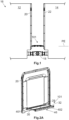
- FIG 1 A first embodiment of a transition bridge 101 according to the present invention is shown in a side view.
- the transition bridge 101 provides a transition between a first vehicle part 12 and a second vehicle part 14 of a vehicle 16, for example, an underground train, a metro, or an articulated bus.
- the first vehicle part 12 and the second vehicle part 14 are shown only in principle.
- the first vehicle part 12 and the second vehicle part 14 are articulated and detachably connected to one another by means of a coupling device 18.
- the first vehicle part 12 forms a first end wall 20, and the second vehicle part 14 forms a second end wall 22.
- a plate level PE is defined, which will be discussed in more detail later.
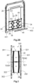
- Figure 2A and 2B show the Figure 1
- the transition bridge 101 shown in FIG. 1 is shown in perspective views in a first rotational position and in a second rotational position. For reasons of clarity, in comparison to Figure 1 in particular the second end wall 22 is not shown.
- the transition bridge 101 comprises two centering elements 34, each with a first end 36 and a second end 38.
- the centering element 34 is designed in the manner of a scissor frame.
- the transition bridge 101 has a first base plate 28, a second base plate 32 and a tread plate 30, which are arranged in a plate plane PE (see Figure 1 ) are movably connected to the centering element 34.
- the first base plate 28 and the second base plate 32 are bent at their free ends facing away from the tread plate 30 by slightly more than 90°.
- the transition bridge 101 is provided with a rotational axis T that is attached to the first end wall 20 or interacts with the first end wall 20 and extends within the plate plane PE or parallel to the plate plane PE.
- This rotational axis T passes through the centering element 34 at the first end 36 for rotatably connecting the centering element 34 to the first end wall 20.
- the features "first end” 36 and “second end” 38 can be interpreted broadly, so that, for example, the rotational axis T could also pass through the centering element 34 somewhat further toward the center.
- transition bridge 101 has a locking device 46, with which the centering element 34 at its second end 38 and/or the second base plate 32 can be releasably connected to the second end wall 22 (see Figure 1 ) can be connected.
- a first end bar 401 is arranged on the first end wall 20 and a second end bar 402 is arranged on the second end wall 22, wherein the rotation axis T is fastened to the first end bar 401.
- the rotation axis T can also be fastened directly to the first end wall 20 (not shown).
- the locking device 46 cooperates with the second end bar to lock the centering element 34 in the Figure 2 shown rotational position.
- the second end wall 22 and/or the second end strip 402 have fastening sections 48 into which counter-fastening sections 50 of the second base plate 32 and/or the centering element 34 can be inserted.
- a reversed arrangement in which the transition bridge 101 is rotatably mounted on a rotation axis T, which is attached to the second end wall 22 or to the second end strip 402, is also conceivable.
- the structure of the transition bridge described above also applies analogously to the reversed arrangement.
- Figure 3 shows a second embodiment of the transition bridge 102 based on a plan view.
- the transition bridge 102 according to the second embodiment has a first subunit 24 and a second subunit 26, which extends between the first end wall 20 and the second end wall 22 and thus provides the transition between the first vehicle part 12 (not shown here) and the second vehicle part 14 (also not shown).
- the first subunit 24 comprises a primary first floor plate 281, a first step plate 301, and a primary second floor plate 321.
- the second subunit 26 comprises a secondary first base plate 282, a second tread plate 302 and a secondary second base plate 322.
- the first subunit 24 and the second subunit 26 are in a first rotational position.
- Figure 4 is the one in the Figures 1 and 2
- the transition bridge 102 shown is shown in a perspective view.
- the first subunit 24 and the second subunit 26 are in a second rotational position in which the first subunit 24 and the second subunit 26 are rotated by approximately 90° relative to the first rotational position.
- Figure 4 clearly shows that the first subunit 24 is rotatably attached to the first end wall 20 and the second subunit 26 is rotatably attached to the second end wall 22, so that a high degree of symmetry of the transition bridge 102 is achieved, whereby the first subunit 24 and the second subunit 26 can be constructed largely identically.
- the first sub-unit 24 further comprises a first centering element 341, with which the primary first floor plate 281, the first tread plate 301 and the primary second floor plate 321 (cf. Figure 3 ) along the Figure 1 defined plate plane PE are movably connected.
- the first centering element 341 forms a Figure 4 hidden primary first end 361 and a primary second end.
- the plate plane PE is essentially defined by the maximum extension of the floor plates 281, 282, 321, 322 and the tread plates 301, 302, so that the plate plane PE follows the rotation between the first rotation position and the second rotation position.
- the first subunit 24 and the second subunit 26 can be moved substantially parallel to the first end wall 20 and the second end wall 22, in other words up and down, but also sideways.
- the first subunit 24 is constructed identically to the second subunit 26. Therefore, the second subunit 26 has a second centering element 342, which Figure 3 is hidden and therefore not visible (see Figure 6 ).
- the second centering element 342 forms a secondary first end 362 and a secondary second end 382.
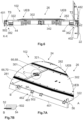
- Figure 5 shows a perspective view of the transition bridge 102 without the first end wall 20. It shows a first end strip 401, which is or can be fastened to the first end wall 20 with fastening means (not shown), such as screws or the like. Accordingly, the transition bridge 102 comprises a second end strip 402, which is fastened to the second end wall 22.
- Figure 6 shows the transition bridge 102 in a sectional view approximately along the Figure 5 defined section plane XX.
- the section plane XX runs through the second subunit 26 and in such a way that the second centering element 342 is visible.
- the second end strip 402 forms a plurality of receiving projections 42, each with a through-bore 44, through which a second axis of rotation T2 runs, wherein the second axis of rotation T2 is formed by a bolt or the like.
- the second centering element 342 is rotatably connected at its secondary first end 362 to the second axis of rotation T2, about which the second subunit 26 is rotatable between the first rotational position and the second rotational position about the second axis of rotation T2, as can be seen, among other things, from a comparison of the Figures 2 and 3 emerges.
- the first end strip 401 also forms corresponding receiving projections 42 and corresponding through holes 44 through which a first rotational axis T1 extends.
- the first centering element 341 is connected to the first rotational axis T1 at its primary first end 361 so as to be rotatable about the first rotational axis T1 (in Figure 6 not visible due to the course of the section plane XX).
- the first subunit 24 is also rotatable between the first rotational position and the second rotational position about the first rotational axis T1, which is also evident from a comparison of the Figures 2 and 3 can be derived.
- Figure 7A shows the Figure 5 defined section A in enlarged form.
- the transition bridge 102 has a second locking device 462, with which the secondary second base plate 322 can be connected to the first end strip 401.
- the first end strip 401 is provided with first fastening sections 481, into which hook-shaped second counter-fastening sections 502 of the second locking device 462 can be brought into positive engagement by means of a movement along the plate plane PE.
- the first fastening sections 481 have an approximately L-shaped cross-section.
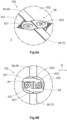
- Figure 7B is a principle and not to scale enlarged sectional view through a Figure 7A marked section B. It can be seen that the second counter-fastening section 502 has a pin 52 that projects laterally therefrom.
- the second sub-unit 26 is first moved from the second rotational position to the first rotational position, wherein the second sub-unit 26 is moved with respect to the plate plane PE such that the pin 52 can be inserted into the first fastening section 481.
- the first fastening sections 481 and the second counter-fastening sections 502 each have insertion bevels 54.
- FIG 8A is the one in the Figures 1 and 2 shown transition bridge 102 is shown in a perspective view, so that the transition bridge 102 is visible from below.
- the first subunit 24 and the second subunit 26 are in the first rotational position.
- Figure 8B shows the Figure 8A defined section D in an enlarged view showing the second subunit 26.
- the second counter-fastening sections 502 are rotatably mounted on the secondary second base plate 322 by means of a bearing axis TS.
- the second counter-fastening sections 502 themselves are connected in a rotationally fixed manner to the bearing axis TS.
- the second centering element 342 is also traversed by the bearing axis TS at its secondary second end 382.
- the bearing axis TS is also rotated about the second rotation axis T2 when the second sub-unit 26 is moved into the second rotation position (see also Figure 6 ).
- the first subunit 24 is constructed accordingly (not shown).
- the second counter-fastening sections 502 come into contact with the base of the first fastening sections 481 in the first rotational position, whereby the first rotational position is determined (see in particular Figure 7A ).
- the first end strip 401 is fastened to the first end wall 20 of the first vehicle part 12.
- the rotational position of the first end strip 401 relative to the second base plate 322 can change, particularly as a result of pitching movements.
- the rotational position of the second counter-fastening sections 502 in the first fastening sections 481 would also change.
- Figure 8C shows the Figure 8A defined section E in an enlarged view.
- the first axis of rotation T1 to which the first centering element 341 is rotatably connected in the region of its primary first end 361 on the first end wall 20.
- the first axis of rotation T1 is fastened to the first end wall 20 or to the first end strip 401 by means of a receiving projection 42.
- the second sub-unit 26 is moved slightly along the plate plane PE. As a result of this movement, the pin 52 is moved into the closed position in Figure 7A left section of the first fastening section 481, so that an undercut and consequently a positive locking with respect to a rotational movement into the second rotational position is achieved. The second subunit 26 is therefore fixed in the first rotational position.
- the first subunit 24 is structurally identical or at least largely identical to the second subunit 26.
- the first end strip 401 is also identical to the second end strip 402. Therefore, the transition bridge 102 comprises a first locking device 461, with which the primary second base plate 321 can be connected to the second end strip 402.
- the second end strip 402 has second fastening sections 482, into which first counter-fastening sections 501 of the first locking device 461 can be introduced in the manner described in order to fix the first subunit 24 in the first rotational position (see, for example, Figures 11 and 12 ).
- Figure 9A shows the Figure 7A defined section C enlarged and from a slightly different perspective and Figure 9B section C using a bottom view.
- the Figures 7 and 8 show a fixing device 58, with which the first tread plate 301 and the second tread plate 302 can be releasably connected to one another when they are in the first rotational position.
- the fixing device 58 comprises a first fixing body 601 and a second fixing body 602, which are each mounted in the first tread plate 301 and the second tread plate 302 so as to be rotatable about a first fixing body axis 621 and a second fixing body axis 622, respectively, and can be turned, for example, with a square wrench.
- Figure 9 It can be seen that the first fixing body 601 and the second fixing body 602 are each hook-shaped.
- Figure 9B the fixing device 58 is in the closed state.
- the first fixing body 601 engages around the second fixing body axis 622 of the second fixing body 602.
- the second fixing body 602 engages around the first fixing body axis 621 of the first fixing body 601.
- the first fixing body 601 and the second fixing body 602 have fixing sections 64 which approximate the shape of the first fixing body axis 621 and the second fixing body axis 622 in order to produce a minimal form fit in the closed state. In the closed state, this prevents movement of the first tread plate 301 and the second tread plate 302 along the plate plane PE.
- first tread plate 301 and the second tread plate 302 cannot be moved along the direction indicated by the arrow R. This prevents the above-mentioned undercut of the pin 52 from being eliminated and the first sub-unit 24 and the second sub-unit 26 from leaving the first rotational position.
- the first fixing body axis 621 and the second fixing body axis 622 can be rotated, for example, by means of a square key.
- Figure 10 shows a sectional view through the transition bridge 102 approximately along the Figure 5 defined cutting plane YY.
- Figure 11 shows the Figure 10 defined section D in an enlarged form.
- a connecting body 66 can be seen, which is divided into a first subsection 68 connected to the first tread plate 301 and a second subsection 70 connected to the second tread plate 302 (see also Figures 7A , 8 and 9 ). Due to the selected cutting plane, the Figures 10 and 11 the second subsection 70 can be seen, which is, however, identical in construction to the first subsection 68.
- the second subsection 70 has an H-shaped cross-section and consequently two recesses 72.
- the second subsection 70 is connected to the second tread plate 302 via one of the recesses 72, the second tread plate 302 resting against the base of the recess 72.
- the first tread plate 301 can be inserted into the opposite recess 72 of the second subsection 70 using the movement described above along the plate plane PE.
- the second subsection 70 has insertion bevels 54.
- a gap remains between the base of the respective recess 72 and the first tread plate 301, for example, in order to be able to compensate for expansion due to temperature increases or tolerance deviations.
- the first tread plate 301 and the second tread plate 302 can be detachably connected to one another using the connecting body 66.
- the transition bridge 102 is loaded more evenly overall.
- the floor plates 281, 282, 321, 322 can additionally or alternatively be connected to the connecting body 66 in the manner described.
- the first subunit 24 and the second subunit 26 do not abut one another along a single parting plane. Rather, the first tread plate 301 and the second tread plate 302 abut one another at a tread plate parting plane TET, the primary first floor plate 281 and the secondary second floor plate 322 abut one another at a first floor plate parting plane TEM1, and the secondary first floor plate 282 and the primary second floor plate 321 abut one another at a second floor plate parting plane TEM2, wherein a gap may remain in each case for the reasons stated.
- the tread plate parting plane TET, the first floor plate parting plane TEM1, and the second floor plate parting plane TEM2 run parallel and offset from one another.
- the first tread plate 301 and the second tread plate 302 are arranged on the floor plates 281, 282, 321, 322 and form an overlapping area UEB. If, for example, the first tread plate 301 is loaded, the offset arrangement of the tread plate separation plane TET, the first floor plate separation plane TEM1 and the second floor plate separation plane TEM2 causes this load not only to the primary first floor plate 281 and the primary second floor plate 321, but also to the secondary second floor plate 322. This also contributes to the transition bridge 102 being loaded more evenly.
- the Figures 12 and 13 each show an enlarged view approximating the Figure 4 defined section E in a first embodiment and a second embodiment, respectively.
- the first subunit 24 is in the second rotational position.
- the transition bridge 102 is equipped with holding means 74.
- holding means 74 comprise in the Figure 12
- a first pin 761 and a second pin 762 are arranged on the first end wall 20 and protrude therefrom.
- the first pin 761 can be inserted into an eyelet of the primary first base plate 281, and the second pin 762 can be inserted into an eyelet of the primary second base plate 321.
- a split pin 78 is inserted into each of the first pin 761 and the second pin 762, thereby holding the first subunit 24 on the first end wall 20 and consequently in the second rotational position.
- the holding devices according to Figure 13 The illustrated embodiment includes two lever locks that cooperate with corresponding locking hooks 80 arranged on the secondary first base plate 282 and the first tread plate 301 to hold the first subunit 24 in the second rotational position. Accordingly, the second subunit 26 can be connected to the second end wall 22 in the second rotational position (not shown).
Landscapes
- Engineering & Computer Science (AREA)
- Life Sciences & Earth Sciences (AREA)
- Wood Science & Technology (AREA)
- Mechanical Engineering (AREA)
- Bridges Or Land Bridges (AREA)
- Mechanical Control Devices (AREA)
Priority Applications (2)
| Application Number | Priority Date | Filing Date | Title |
|---|---|---|---|
| EP23213686.1A EP4563435B1 (fr) | 2023-12-01 | 2023-12-01 | Passerelle de transition pour fournir une transition entre une première partie de véhicule et une seconde partie de véhicule d'un véhicule ainsi que véhicule équipé d'une telle passerelle de transition |
| CN202411465348.8A CN120080882A (zh) | 2023-12-01 | 2024-10-21 | 用于在车辆的第一车辆部分和第二车辆部分之间提供过渡的过渡桥以及具有这种过渡桥的车辆 |
Applications Claiming Priority (1)
| Application Number | Priority Date | Filing Date | Title |
|---|---|---|---|
| EP23213686.1A EP4563435B1 (fr) | 2023-12-01 | 2023-12-01 | Passerelle de transition pour fournir une transition entre une première partie de véhicule et une seconde partie de véhicule d'un véhicule ainsi que véhicule équipé d'une telle passerelle de transition |
Publications (2)
| Publication Number | Publication Date |
|---|---|
| EP4563435A1 true EP4563435A1 (fr) | 2025-06-04 |
| EP4563435B1 EP4563435B1 (fr) | 2026-04-15 |
Family
ID=89073384
Family Applications (1)
| Application Number | Title | Priority Date | Filing Date |
|---|---|---|---|
| EP23213686.1A Active EP4563435B1 (fr) | 2023-12-01 | 2023-12-01 | Passerelle de transition pour fournir une transition entre une première partie de véhicule et une seconde partie de véhicule d'un véhicule ainsi que véhicule équipé d'une telle passerelle de transition |
Country Status (2)
| Country | Link |
|---|---|
| EP (1) | EP4563435B1 (fr) |
| CN (1) | CN120080882A (fr) |
Citations (13)
| Publication number | Priority date | Publication date | Assignee | Title |
|---|---|---|---|---|
| US4318345A (en) * | 1979-03-03 | 1982-03-09 | Maschinenfabrik Augsburg-Nuernberg A.G. | Railway vestibule connection |
| EP0331121A2 (fr) | 1988-03-02 | 1989-09-06 | HÜBNER Gummi- und Kunststoff GmbH | Elément de passerelle d'intercommunication séparable pour véhicules |
| EP0669243A1 (fr) | 1994-02-25 | 1995-08-30 | HÜBNER Gummi- und Kunststoff GmbH | Eléments d'une passerelle d'intercommunication mobile en diagonale entre deux véhicules |
| EP0722873A1 (fr) | 1995-01-19 | 1996-07-24 | HÜBNER Gummi- und Kunststoff GmbH | Passerelle |
| EP0958981A1 (fr) | 1998-05-16 | 1999-11-24 | HÜBNER Gummi- und Kunststoff GmbH | Passage entre deux véhicules ou parties de véhicule reliés de manière articulée notamment entre deux autorails reliés de manière articulée |
| EP2457796A1 (fr) | 2010-11-26 | 2012-05-30 | Hübner GmbH | Pont d'un passage entre deux véhicules reliés de manière articulée |
| EP2500230A1 (fr) * | 2011-03-18 | 2012-09-19 | Hübner GmbH | Pont d'un passage entre deux éléments de véhicule reliés de manière articulée |
| CN202879493U (zh) * | 2012-07-29 | 2013-04-17 | 中国北车集团大连机车车辆有限公司 | 机车通过连接器 |
| EP2700553A1 (fr) | 2012-08-22 | 2014-02-26 | Hübner GmbH | Pont d'un passage avec un soufflet circonférentiel en forme de tunnel entre deux véhicules reliés par une liaison articulée |
| DE202015103938U1 (de) * | 2015-07-28 | 2015-08-24 | Manfred Teufl | Tragvorrichtung und Bodensystem zwischen zwei gelenkig verbundenen Fahrzeugteilen |
| CN106891906A (zh) * | 2017-03-22 | 2017-06-27 | 青岛欧特美股份有限公司 | 一种具有垂向缓冲功能的一片式侧护板装置 |
| EP3530496A1 (fr) * | 2018-02-27 | 2019-08-28 | Narita Mfg., Ltd. | Dispositif d'expansion de panneaux |
| EP4035911A1 (fr) | 2021-01-28 | 2022-08-03 | ULTIMATE Europe Transportation Equipment GmbH | Pont pour une transition entre deux parties de véhicule reliées de manière articulée l'une à l'autre |
-
2023
- 2023-12-01 EP EP23213686.1A patent/EP4563435B1/fr active Active
-
2024
- 2024-10-21 CN CN202411465348.8A patent/CN120080882A/zh not_active Withdrawn
Patent Citations (13)
| Publication number | Priority date | Publication date | Assignee | Title |
|---|---|---|---|---|
| US4318345A (en) * | 1979-03-03 | 1982-03-09 | Maschinenfabrik Augsburg-Nuernberg A.G. | Railway vestibule connection |
| EP0331121A2 (fr) | 1988-03-02 | 1989-09-06 | HÜBNER Gummi- und Kunststoff GmbH | Elément de passerelle d'intercommunication séparable pour véhicules |
| EP0669243A1 (fr) | 1994-02-25 | 1995-08-30 | HÜBNER Gummi- und Kunststoff GmbH | Eléments d'une passerelle d'intercommunication mobile en diagonale entre deux véhicules |
| EP0722873A1 (fr) | 1995-01-19 | 1996-07-24 | HÜBNER Gummi- und Kunststoff GmbH | Passerelle |
| EP0958981A1 (fr) | 1998-05-16 | 1999-11-24 | HÜBNER Gummi- und Kunststoff GmbH | Passage entre deux véhicules ou parties de véhicule reliés de manière articulée notamment entre deux autorails reliés de manière articulée |
| EP2457796A1 (fr) | 2010-11-26 | 2012-05-30 | Hübner GmbH | Pont d'un passage entre deux véhicules reliés de manière articulée |
| EP2500230A1 (fr) * | 2011-03-18 | 2012-09-19 | Hübner GmbH | Pont d'un passage entre deux éléments de véhicule reliés de manière articulée |
| CN202879493U (zh) * | 2012-07-29 | 2013-04-17 | 中国北车集团大连机车车辆有限公司 | 机车通过连接器 |
| EP2700553A1 (fr) | 2012-08-22 | 2014-02-26 | Hübner GmbH | Pont d'un passage avec un soufflet circonférentiel en forme de tunnel entre deux véhicules reliés par une liaison articulée |
| DE202015103938U1 (de) * | 2015-07-28 | 2015-08-24 | Manfred Teufl | Tragvorrichtung und Bodensystem zwischen zwei gelenkig verbundenen Fahrzeugteilen |
| CN106891906A (zh) * | 2017-03-22 | 2017-06-27 | 青岛欧特美股份有限公司 | 一种具有垂向缓冲功能的一片式侧护板装置 |
| EP3530496A1 (fr) * | 2018-02-27 | 2019-08-28 | Narita Mfg., Ltd. | Dispositif d'expansion de panneaux |
| EP4035911A1 (fr) | 2021-01-28 | 2022-08-03 | ULTIMATE Europe Transportation Equipment GmbH | Pont pour une transition entre deux parties de véhicule reliées de manière articulée l'une à l'autre |
Also Published As
| Publication number | Publication date |
|---|---|
| CN120080882A (zh) | 2025-06-03 |
| EP4563435B1 (fr) | 2026-04-15 |
Similar Documents
| Publication | Publication Date | Title |
|---|---|---|
| EP3597488A1 (fr) | Système de blocage et de contact permettant de raccorder électriquement un réseau de bord d'un véhicule automobile à un siège de véhicule amovible ou une installation de siège | |
| DE102009048894B4 (de) | System zur Befestigung eines Sitzes, insbesondere eines Luftfahrzeugs, und ein solches System aufweisender Sitz | |
| WO2008113610A2 (fr) | Dispositif servant à fixer des objets | |
| DE102021107936A1 (de) | Automatische Mittelpufferkupplung für Schienenfahrzeuge sowie hieraus zusammengesetzte Kupplungsanordnung | |
| EP2013441B1 (fr) | Dispositif de fixation verticale de tubes | |
| WO2012038253A1 (fr) | Système de fixation | |
| EP0407767B1 (fr) | Dispositif de support pour un rideau | |
| EP1900552B1 (fr) | Anneau de remorquage pour une barre à rotule | |
| EP3287305B1 (fr) | Structure articulee et passage comprenant une structure articulee | |
| EP0071728A1 (fr) | Agencement de masses de ballast pour tracteurs agricoles | |
| EP2576314B1 (fr) | Dispositif de blocage pour systèmes de manoeuvre d'aiguille | |
| EP1597098A1 (fr) | Dispositif d'attelage pour vehicules de traction | |
| DE69933475T3 (de) | Schnellentriegelbare und -verriegelbare abdeckung | |
| DE69222917T2 (de) | Verbindung des Untergestells eines Krans an die Raupenkette(n) | |
| EP4563435B1 (fr) | Passerelle de transition pour fournir une transition entre une première partie de véhicule et une seconde partie de véhicule d'un véhicule ainsi que véhicule équipé d'une telle passerelle de transition | |
| DE202009001046U1 (de) | Übergang zwischen Fahrzeugteilen | |
| DE3639738C2 (de) | Mechanismus zum Versetzen und Verriegeln eines mittels Haken zwischen Pfosten gehaltenen flächigen Teils | |
| EP4219304A1 (fr) | Dispositif d'accouplement pour une bielle de liaison | |
| EP3265359B1 (fr) | Articulation tournante pour la liaison par articulation tournante de véhicules ferroviaires | |
| EP0603559B1 (fr) | Attelage de remorque amovible | |
| EP1415043A1 (fr) | Voie de vehicule ferroviaire | |
| EP1195310B1 (fr) | Dispositif de réglage de la symmétrie dans un système de manoeuvre d'aiguilles | |
| DE102020205909A1 (de) | Umsetzanordnung für eine Aufzugsanlage | |
| DE69608036T2 (de) | Ineinandergreifende, spielfreie Kupplungsstangen-Anordnung für Eisenbahn-Güterwagen und ein Verriegelungsmechanismus dafür | |
| EP1619101A1 (fr) | Accouplement pour le service et le remorquage, avec barre d'attelage articulée |
Legal Events
| Date | Code | Title | Description |
|---|---|---|---|
| PUAI | Public reference made under article 153(3) epc to a published international application that has entered the european phase |
Free format text: ORIGINAL CODE: 0009012 |
|
| STAA | Information on the status of an ep patent application or granted ep patent |
Free format text: STATUS: THE APPLICATION HAS BEEN PUBLISHED |
|
| AK | Designated contracting states |
Kind code of ref document: A1 Designated state(s): AL AT BE BG CH CY CZ DE DK EE ES FI FR GB GR HR HU IE IS IT LI LT LU LV MC ME MK MT NL NO PL PT RO RS SE SI SK SM TR |
|
| STAA | Information on the status of an ep patent application or granted ep patent |
Free format text: STATUS: REQUEST FOR EXAMINATION WAS MADE |
|
| 17P | Request for examination filed |
Effective date: 20250922 |
|
| GRAP | Despatch of communication of intention to grant a patent |
Free format text: ORIGINAL CODE: EPIDOSNIGR1 |
|
| STAA | Information on the status of an ep patent application or granted ep patent |
Free format text: STATUS: GRANT OF PATENT IS INTENDED |
|
| INTG | Intention to grant announced |
Effective date: 20251208 |
|
| GRAS | Grant fee paid |
Free format text: ORIGINAL CODE: EPIDOSNIGR3 |
|
| GRAA | (expected) grant |
Free format text: ORIGINAL CODE: 0009210 |
|
| STAA | Information on the status of an ep patent application or granted ep patent |
Free format text: STATUS: THE PATENT HAS BEEN GRANTED |
|
| AK | Designated contracting states |
Kind code of ref document: B1 Designated state(s): AL AT BE BG CH CY CZ DE DK EE ES FI FR GB GR HR HU IE IS IT LI LT LU LV MC ME MK MT NL NO PL PT RO RS SE SI SK SM TR |
|
| REG | Reference to a national code |
Ref country code: CH Ref legal event code: F10 Free format text: ST27 STATUS EVENT CODE: U-0-0-F10-F00 (AS PROVIDED BY THE NATIONAL OFFICE) Effective date: 20260415 |
|
| REG | Reference to a national code |
Ref country code: DE Ref legal event code: R096 Ref document number: 502023003760 Country of ref document: DE |
|
| REG | Reference to a national code |
Ref country code: CH Ref legal event code: R17 Free format text: ST27 STATUS EVENT CODE: U-0-0-R10-R17 (AS PROVIDED BY THE NATIONAL OFFICE) Effective date: 20260501 |