EP2701290A1 - Dispositif de génération de puissance - Google Patents
Dispositif de génération de puissance Download PDFInfo
- Publication number
- EP2701290A1 EP2701290A1 EP12773840.9A EP12773840A EP2701290A1 EP 2701290 A1 EP2701290 A1 EP 2701290A1 EP 12773840 A EP12773840 A EP 12773840A EP 2701290 A1 EP2701290 A1 EP 2701290A1
- Authority
- EP
- European Patent Office
- Prior art keywords
- permanent magnet
- magnet member
- electromotive coil
- electromotive
- permanent
- Prior art date
- Legal status (The legal status is an assumption and is not a legal conclusion. Google has not performed a legal analysis and makes no representation as to the accuracy of the status listed.)
- Granted
Links
Images




Classifications
-
- H—ELECTRICITY
- H02—GENERATION; CONVERSION OR DISTRIBUTION OF ELECTRIC POWER
- H02K—DYNAMO-ELECTRIC MACHINES
- H02K16/00—Machines with more than one rotor or stator
- H02K16/02—Machines with one stator and two or more rotors
-
- H—ELECTRICITY
- H02—GENERATION; CONVERSION OR DISTRIBUTION OF ELECTRIC POWER
- H02K—DYNAMO-ELECTRIC MACHINES
- H02K1/00—Details of the magnetic circuit
- H02K1/06—Details of the magnetic circuit characterised by the shape, form or construction
- H02K1/12—Stationary parts of the magnetic circuit
- H02K1/17—Stator cores with permanent magnets
-
- H—ELECTRICITY
- H02—GENERATION; CONVERSION OR DISTRIBUTION OF ELECTRIC POWER
- H02K—DYNAMO-ELECTRIC MACHINES
- H02K1/00—Details of the magnetic circuit
- H02K1/06—Details of the magnetic circuit characterised by the shape, form or construction
- H02K1/22—Rotating parts of the magnetic circuit
- H02K1/27—Rotor cores with permanent magnets
-
- H—ELECTRICITY
- H02—GENERATION; CONVERSION OR DISTRIBUTION OF ELECTRIC POWER
- H02K—DYNAMO-ELECTRIC MACHINES
- H02K1/00—Details of the magnetic circuit
- H02K1/06—Details of the magnetic circuit characterised by the shape, form or construction
- H02K1/22—Rotating parts of the magnetic circuit
- H02K1/27—Rotor cores with permanent magnets
- H02K1/2706—Inner rotors
- H02K1/272—Inner rotors the magnetisation axis of the magnets being perpendicular to the rotor axis
- H02K1/274—Inner rotors the magnetisation axis of the magnets being perpendicular to the rotor axis the rotor consisting of two or more circumferentially positioned magnets
-
- H—ELECTRICITY
- H02—GENERATION; CONVERSION OR DISTRIBUTION OF ELECTRIC POWER
- H02K—DYNAMO-ELECTRIC MACHINES
- H02K1/00—Details of the magnetic circuit
- H02K1/06—Details of the magnetic circuit characterised by the shape, form or construction
- H02K1/22—Rotating parts of the magnetic circuit
- H02K1/27—Rotor cores with permanent magnets
- H02K1/2706—Inner rotors
- H02K1/272—Inner rotors the magnetisation axis of the magnets being perpendicular to the rotor axis
- H02K1/274—Inner rotors the magnetisation axis of the magnets being perpendicular to the rotor axis the rotor consisting of two or more circumferentially positioned magnets
- H02K1/2753—Inner rotors the magnetisation axis of the magnets being perpendicular to the rotor axis the rotor consisting of two or more circumferentially positioned magnets the rotor consisting of magnets or groups of magnets arranged with alternating polarity
-
- H—ELECTRICITY
- H02—GENERATION; CONVERSION OR DISTRIBUTION OF ELECTRIC POWER
- H02K—DYNAMO-ELECTRIC MACHINES
- H02K1/00—Details of the magnetic circuit
- H02K1/06—Details of the magnetic circuit characterised by the shape, form or construction
- H02K1/22—Rotating parts of the magnetic circuit
- H02K1/27—Rotor cores with permanent magnets
- H02K1/2706—Inner rotors
- H02K1/272—Inner rotors the magnetisation axis of the magnets being perpendicular to the rotor axis
- H02K1/274—Inner rotors the magnetisation axis of the magnets being perpendicular to the rotor axis the rotor consisting of two or more circumferentially positioned magnets
- H02K1/2753—Inner rotors the magnetisation axis of the magnets being perpendicular to the rotor axis the rotor consisting of two or more circumferentially positioned magnets the rotor consisting of magnets or groups of magnets arranged with alternating polarity
- H02K1/278—Surface mounted magnets; Inset magnets
-
- H—ELECTRICITY
- H02—GENERATION; CONVERSION OR DISTRIBUTION OF ELECTRIC POWER
- H02K—DYNAMO-ELECTRIC MACHINES
- H02K21/00—Synchronous motors having permanent magnets; Synchronous generators having permanent magnets
- H02K21/02—Details
- H02K21/04—Windings on magnets for additional excitation ; Windings and magnets for additional excitation
-
- H—ELECTRICITY
- H02—GENERATION; CONVERSION OR DISTRIBUTION OF ELECTRIC POWER
- H02K—DYNAMO-ELECTRIC MACHINES
- H02K21/00—Synchronous motors having permanent magnets; Synchronous generators having permanent magnets
- H02K21/12—Synchronous motors having permanent magnets; Synchronous generators having permanent magnets with stationary armatures and rotating magnets
-
- H—ELECTRICITY
- H02—GENERATION; CONVERSION OR DISTRIBUTION OF ELECTRIC POWER
- H02K—DYNAMO-ELECTRIC MACHINES
- H02K21/00—Synchronous motors having permanent magnets; Synchronous generators having permanent magnets
- H02K21/12—Synchronous motors having permanent magnets; Synchronous generators having permanent magnets with stationary armatures and rotating magnets
- H02K21/14—Synchronous motors having permanent magnets; Synchronous generators having permanent magnets with stationary armatures and rotating magnets with magnets rotating within the armatures
- H02K21/16—Synchronous motors having permanent magnets; Synchronous generators having permanent magnets with stationary armatures and rotating magnets with magnets rotating within the armatures having annular armature cores with salient poles
-
- H—ELECTRICITY
- H02—GENERATION; CONVERSION OR DISTRIBUTION OF ELECTRIC POWER
- H02K—DYNAMO-ELECTRIC MACHINES
- H02K21/00—Synchronous motors having permanent magnets; Synchronous generators having permanent magnets
- H02K21/12—Synchronous motors having permanent magnets; Synchronous generators having permanent magnets with stationary armatures and rotating magnets
- H02K21/22—Synchronous motors having permanent magnets; Synchronous generators having permanent magnets with stationary armatures and rotating magnets with magnets rotating around the armatures, e.g. flywheel magnetos
-
- H—ELECTRICITY
- H02—GENERATION; CONVERSION OR DISTRIBUTION OF ELECTRIC POWER
- H02K—DYNAMO-ELECTRIC MACHINES
- H02K21/00—Synchronous motors having permanent magnets; Synchronous generators having permanent magnets
- H02K21/26—Synchronous motors having permanent magnets; Synchronous generators having permanent magnets with rotating armatures and stationary magnets
-
- H—ELECTRICITY
- H02—GENERATION; CONVERSION OR DISTRIBUTION OF ELECTRIC POWER
- H02K—DYNAMO-ELECTRIC MACHINES
- H02K3/00—Details of windings
- H02K3/46—Fastening of windings on the stator or rotor structure
- H02K3/47—Air-gap windings, i.e. iron-free windings
Definitions
- the present invention relates to a power generator which induces power generation by relative rotation between a permanent magnet and an electromotive coil.
- a permanent magnet member provided with permanent magnets arranged in the form of a tube and an electromotive coil member provided with electromotive coils arranged in the form of a tube are arranged concentrically.
- the single permanent magnet member and the single electromotive coil member are arranged concentrically. In this state, the single permanent magnet member is rotated to change magnetic force in the electromotive coil, and, thus, to induce power generation.
- Patent Document 1 JP 3709145 B1
- the power generator disclosed in the Patent Document 1 is based on the idea of fitting an electromagnet with a single permanent magnet member and changing the magnetic force acting on an electromotive coil by the electromagnet to obtain efficient power generation.
- the power generator according to the present invention is provided with a first permanent magnet member and a second permanent magnet member which are arranged concentrically to have a telescoping structure, and the first and second permanent magnet members cooperate with each other to change the magnetic force acting on an electromotive coil, and, thus, to obtain efficient power generation.
- the power generator according to the present invention is provided with a first permanent magnet member, a second permanent magnet member, and an electromotive coil member which are arranged concentrically to have a telescoping structure and is configured so that power generation in the electromotive coil member is induced by rotating the first permanent magnet member or/and the second permanent magnet member.
- the first and second permanent magnet members cooperate with each other to change magnetic force, and, thus, to obtain efficient power generation.
- one of the first permanent magnet member and the second permanent magnet member is positively rotated and the other is reversely rotated, and the rotation speeds of them are substantially increased, whereby the power generation efficiency can be improved.
- the power generator is provided with a first permanent magnet member, a second permanent magnet member, and an electromotive coil member arranged concentrically to have a telescoping structure and is configured so that power generation in the electromotive coil member is induced by rotating the electromotive coil member.
- the first and second permanent magnet members cooperate with each other to change the magnetic force and, thus, to obtain efficient power generation.
- the electromotive coil member is disposed concentrically outward the first and second permanent magnet members, or the electromotive coil member in which electromotive coils constituted of air core coils are arranged is disposed concentrically between the first permanent magnet member and the second permanent magnet member.
- the electromotive coil member in which the electromotive coils constituted of air core coils are arranged is disposed concentrically between the first permanent magnet member and the second permanent magnet member.
- the first and second permanent magnet members are provided with a large number of permanent magnets with opposite polarities in the radial direction which are arranged in the circumferential direction, and the magnetic change with reliability is realized to obtain efficient power generation.
- the number of the permanent magnets of one of the first and second permanent magnet members is an integral multiple of the number of the permanent magnets of the other permanent magnet member, the permanent magnets of the one of the first and second permanent magnet members are arranged adjacent to each other so that their polarities are opposite to each other, and, at the same time, the permanent magnets of the other permanent magnet member are arranged adjacent to each other so that their polarities are opposite to each other, whereby the magnetic change is caused frequently to obtain efficient power generation.
- the magnetic force acting on the electromotive coil is changed by the cooperation between the first and second permanent magnet members, whereby efficient power generation can be obtained.
- the first and second permanent magnet members are constituted of a large number of the permanent magnets with opposite polarities in the radial direction which are arranged in the circumferential direction. Consequently, the permanent magnet of the first permanent magnet member and the permanent magnet of the second permanent magnet member face each other in the radial direction, and the magnetic force is increased or reduced between the opposite polarities (N pole and S pole) of the facing permanent magnets and between the same polarities (S pole and S pole or N pole and N pole) of the facing permanent magnets, whereby the magnetic force can be changed.
- the number of the permanent magnets of one of the first and second permanent magnet members is an integral multiple of the number of the permanent magnets of the other permanent magnet member, and the permanent magnets of the one permanent magnet member are arranged adjacent to each other so that their polarities are opposite to each other. Consequently, the number of the permanent magnets of the first permanent magnet member and the permanent magnets of the second permanent magnet member with opposite polarities that face each other and the number of the permanent magnets of the first permanent magnet member and the permanent magnets of the second permanent magnet member with the same polarity that face each other are increased to make the magnetic change occur frequently, whereby efficient power generation can be obtained.
- FIGS. 1 to 9 best modes for carrying out the invention will be described based on FIGS. 1 to 9 .
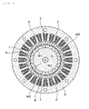
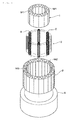
- a first permanent magnet member 1 provided with permanent magnets M1 arranged in a tubular or annular form, a second permanent magnet member 2 provided with permanent magnets M2 arranged in a tubular or annular form, and an electromotive coil member 3 provided with electromotive coils C arranged in a tubular or annular form are arranged concentrically to have a telescoping structure.
- the first permanent magnet member 1 is constituted of a large number of permanent magnets M1 whose polarities are opposite to each other in the radial direction, that is, a large number of the permanent magnets M1 with opposite polarities on the outer peripheral surface and the inner peripheral surface which are arranged in the circumferential direction.
- the second permanent magnet member 2 is constituted of a large number of permanent magnets M2 whose polarities are opposite to each other in the radial direction, that is, a large number of the permanent magnets M2 with opposite polarities on the outer peripheral surface and the inner peripheral surface which are arranged in the circumferential direction.
- the number of either of the permanent magnets M 1 and the permanent magnets M2 is preferably an integral multiple of the number of the other permanent magnets. In the examples 1 to 3 to be described later, the number of the permanent magnets M2 is doubled the number of the permanent magnets M1.
- a large number of the permanent magnets M1 are arranged adjacent to each other so that their polarities are opposite to each other.
- the polarity of the outer peripheral surface of the permanent magnet M1 adjacent to the permanent magnet M1 whose polarity on the outer peripheral surface is N pole is S pole (the polarity on the inner peripheral surface is N pole).
- the permanent magnets M2 are arranged adjacent to each other so that their polarities are opposite to each other.
- the polarity on the outer peripheral surface of the permanent magnet M2 adjacent to the permanent magnet M2 whose polarity on the outer peripheral surface is N pole is S pole (the polarity of the inner peripheral surface is N pole).
- the permanent magnets M1 constituted of magnetic shells having a circular-arc cross section are assembled in a tubular or annular form.
- the permanent magnets M1 magnetizes a tubular or rod-like magnetic body so as to have the above polarity arrangement, whereby the first permanent magnet member 1 is formed.
- the magnetizing is performed in a straight form along a central axis direction of the magnetic body or is performed on a skew with an inclination angle in a coaxial direction.
- the permanent magnets M1 may be buried in a peripheral surface of a rotation shaft 4 or a fixing shaft 4' to be described later, and be arranged in a tubular or annular form, thereby forming the first permanent magnet member 1.
- the permanent magnets M2 constituted of magnetic shells having a circular-arc cross section are assembled in a tubular or annular form.
- the permanent magnets M2 magnetizes a tubular magnetic body so as to have the above polarity arrangement, whereby the second permanent magnet member 2 is formed.
- the magnetizing is also performed in a straight form along a central axial direction of the magnetic body or is performed on a skew with an inclination angle in a coaxial direction.
- the second permanent magnet member 2 has a larger diameter than the first permanent magnet member 1 and is disposed concentrically outward the first permanent magnet member 1.
- the present invention includes a case where the first permanent magnet member 1 has stages 1A and 1B and the second permanent magnet member 2 has stages 2A and 2B, as well as a case where each segment (1A and 1B or 2A and 2B) is a single member.
- the electromotive coil member 3 is constituted of a large number of electromotive coils C arranged in the circumferential direction and is arranged concentrically with the first and second permanent magnet members 1 and 2.
- the electromotive coil member 3 is disposed concentrically outward the first and second permanent magnet members 1 and 2 as shown in the example 1 to be described later, or the electromotive coil member 3 is disposed concentrically between the first permanent magnet member 1 and the second permanent magnet member 2 as shown in the examples 2 and 3 to be described later.
- the first permanent magnet member 1 and the second permanent magnet member 2 cooperate with each other to change the magnetic force, whereby efficient power generation can be induced.
- the thickness, the magnetic force, and the number of the permanent magnets M1 and M2 can be set freely, so that the magnetic force change can be improved.
- the permanent magnets M 1 and M2 of the first and second permanent magnet members 1 and 2 are arranged adjacent to each other in a tubular form as shown in the drawing, they may be arranged at a distance in the circumferential direction.
- a first tubular yoke 5 is fitted onto a rotation shaft 4 rotated by a power source 9 such as a motor, a turbine, and an engine, and the first permanent magnet member 1 is fitted onto the first tubular yoke 5.
- a power source 9 such as a motor, a turbine, and an engine
- the first permanent magnet member 1 is fitted onto the first tubular yoke 5.
- the second permanent magnet member 2 is disposed concentrically at a distance in the radial direction from the first permanent magnet member 1.
- the electromotive coil member 3 is fitted onto the second permanent magnet member 2, and a second tubular yoke 6 is fitter onto the electromotive coil member 3.
- the first permanent magnet member 1, the second permanent magnet member 2, and the electromotive coil member 3 arranged concentrically to have a telescoping structure are provided.
- the first permanent magnet member 1 is rotated to fix the second permanent magnet member 2 and the electromotive coil member 3, and the first permanent magnet member 1, the second permanent magnet member 2, and the electromotive coil member 3 are relatively rotated.
- the power generation in the electromotive coil member 3 is induced by the relative rotation.
- the electromotive coil C of the electromotive coil member 3 is formed by winding winding wires 8 around a plurality of cores 7 arranged on the inner peripheral surface of the second tubular yoke 6 at a distance in the circumferential direction.
- Each of the cores 7 is formed by stacking silicon steel plates and adhered to the outer peripheral surface of each of the permanent magnets M2 of the second permanent magnet member 2.
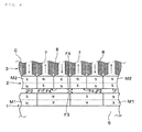
- the number of the permanent magnets M2 of the second permanent magnet member 2 is doubled the number of the permanent magnets M1 of the first permanent magnet member 1, and the permanent magnets M1 and M2 are faced in the radial direction. Namely, the outer peripheral surface of the one permanent magnet M1 faces the inner peripheral surfaces of the two permanent magnets M2.
- the permanent magnets M2 are arranged adjacent to each other so that their polarities are opposite to each other, the permanent magnet M2 having the inner peripheral surface of the same polarity (for example, N pole) as the polarity (N pole) of the outer peripheral surface of the permanent magnet M1 and the permanent magnet M2 having the inner peripheral surface of the opposite polarity (S pole) face the outer peripheral surface of the one permanent magnet M1, so that the magnetic force change to be described later occurs frequently, whereby efficient power generation can be obtained.
- the same polarity for example, N pole
- S pole opposite polarity
- the first permanent magnet member 1 rotates to rotate each of the permanent magnets M1, whereby the magnetic force in the direction shown by F1 and the magnetic force in the direction shown by F2 alternately act on the electromotive coil C through the core 7 adhered to the outer peripheral surface of each of the permanent magnets M2 to change the magnetic force in the electromotive coil C, and, thus, to induce efficient power generation.
- the facing interval between the permanent magnet M1 of the first permanent magnet member 1 and the permanent magnet M2 of the second permanent magnet member 2 is reduced as far as possible to flow the magnetic force effectively.
- a first tubular yoke 5 is fitted onto a fixing shaft 4', and the first permanent magnet member 1 is fitted onto the first tubular yoke 5.
- the electromotive coil member 3 is rotatably disposed coaxially at a distance in the radial direction from the first permanent magnet member 1, and the second permanent magnet member 2 is fixed and coaxially disposed at a distance in the radial direction from the electromotive coil member 3.
- a second tubular yoke 6 is fitted onto the second permanent magnet member 2.
- the electromotive coil member 3 is rotated by a power source 9 such as a motor, a turbine, and an engine.
- the first permanent magnet member 1, the second permanent magnet member 2, and the electromotive coil member 3 arranged concentrically to have a telescoping structure are provided.
- the electromotive coil member 3 is rotated to fix the first and second permanent magnet members 1 and 2, and the electromotive coil member 3 and the first and second permanent magnet members 1 and 2 are relatively rotated.
- the power generation in the electromotive coil member 3 is induced by the relative rotation.
- the electromotive coil member 3 is coreless and is provided with an electromotive coil C constituted of an air core coil around which a winding wire 8 is wound in a tubular or annular form, and the electromotive coils C are connected in a tubular or annular form to form the electromotive coil member 3.
- each of the electromotive coils C constituted of the air core coil is held from the inside and the outside between two tubular bodies constituted of a nonmagnetic body such as glass to form the electromotive coil member 3.
- the electromotive coil C may be a core coil.
- the number of the permanent magnets M2 of the second permanent magnet member 2 is doubled the number of the permanent magnets M1 of the first permanent magnet member 1, and the permanent magnets M1 and M2 are faced in the radial direction. Namely, the outer peripheral surface of the one permanent magnet M1 and the inner peripheral surfaces of the two permanent magnets M2 are faced each other, and the electromotive coil C is interposed in the facing interval.
- the permanent magnets M2 are arranged adjacent to each other to have the polarities be opposite to each other, the permanent magnet M2 having the inner peripheral surface of the same polarity (for example, N pole) as the polarity (N pole) of the outer peripheral surface of the permanent magnet M1 and the permanent magnet M2 having the inner peripheral surface of the opposite polarity (S pole) face the outer peripheral surface of the one permanent magnet M1, so that the magnetic change to be described later occurs frequently, whereby efficient power generation can be achieved.
- the same polarity for example, N pole
- S pole opposite polarity
- the electromotive coil member 3 rotates between the permanent magnet M1 of the first permanent magnet member 1 and the permanent magnet M2 of the second permanent magnet member 2, and the magnetic force changes in the directions shown by F1 to F4 in FIG. 9 , whereby efficient power generation is induced.
- the electromotive coil C is interposed in the facing interval between the permanent magnet M1 and the permanent magnet M2, so that the facing interval increases. Therefore, it is desirable to efficiently utilize the magnetic forces derived from the permanent magnets M1 and M2 either by increasing to some extent the magnetic forces derived from the permanent magnets M1 and M2 or by using under cryogenic conditions near absolute zero at which a superconducting phenomenon occurs.
- a first tubule yoke 5 is fitted onto a rotation shaft 4 rotated by a power source 9 such as a motor, a turbine, and an engine, and the first permanent magnet member 1 is fitted onto the first tubule yoke 5.
- a power source 9 such as a motor, a turbine, and an engine
- the first permanent magnet member 1 is fitted onto the first tubule yoke 5.
- the electromotive coil member 3 is fixed and concentrically disposed at a distance in the radial direction from the first permanent magnet member 1, the second permanent magnet member 2 is rotatably disposed concentrically at a distance in the radial direction from the electromotive coil member 3, and a second tubular yoke 6 is fitted onto the second permanent magnet member 2.
- the second permanent magnet member 2 is rotated by a power source 10 such as a motor, a turbine, and an engine.
- the power source 9 and the power source 10 may be the same power source.
- the first permanent magnet member 1, the second permanent magnet member 2, and the electromotive coil member 3 arranged concentrically to have a telescoping structure are provided.
- the electromotive coil member 3 is fixed to rotate the first and second permanent magnet members 1 and 2, and the electromotive coil member 3 and the first and second permanent magnet members 1 and 2 are relatively rotated.
- the power generation in the electromotive coil member 3 is induced by the relative rotation.
- the electromotive coil member 3 is coreless and is provided with an electromotive coil C constituted of an air core coil around which a winding wire 8 is wound in a tubular or annular form, and the electromotive coils C are connected in a tubular or annular form to form the electromotive coil member 3.
- each of the electromotive coils C constituted of the air core coil is held from the inside and the outside between two tubular bodies constituted of a nonmagnetic body such as glass to form the electromotive coil member 3.
- the electromotive coil C may be a core coil.
- the number of the permanent magnets M2 of the second permanent magnet member 2 is doubled the number of the permanent magnets M1 of the first permanent magnet member 1, and the permanent magnets M1 and M2 are faced in the radial direction. Namely, the outer peripheral surface of the one permanent magnet M1 and the inner peripheral surfaces of the two permanent magnets M2 are faced each other, and the electromotive coil C is interposed in the facing interval.
- the permanent magnets M2 are arranged adjacent to each other so that their polarities are opposite to each other, the permanent magnet M2 having the inner peripheral surfaces of the same polarity (for example, N pole) as the polarity (N pole) of the outer peripheral surface of the permanent magnet M1 and the permanent magnet M2 having the inner peripheral surface of the opposite polarity (S pole) face the outer peripheral surface of the one permanent magnet M1, so that the magnetic change to be described later occurs frequently, whereby efficient power generation can be achieved.
- the same polarity for example, N pole
- S pole opposite polarity
- the first permanent magnet member 1 and the second permanent magnet member 2 rotate while holding the electromotive coil member 3 between them, and the magnetic force changes in the directions shown by F1 to F4 in FIG. 9 in each of the electromotive coils C between the permanent magnet M1 and the permanent magnet M2, whereby efficient power generation is induced.
- first and second permanent magnet members 1 and 2 may be rotated at the same speed in the same direction, or one permanent magnet member and the other permanent magnet member may be rotated at different speeds in the same direction.
- one of the first and second permanent magnet members 1 and 2 is positively rotated and the other is reversely rotated, and their rotation speeds are substantially increased, whereby the power generation efficiency can be improved.
- the electromotive coil C is interposed in the facing interval between the permanent magnets M1 and M2, so that the facing interval increases. Therefore, it is desirable to efficiently utilize the magnetic forces derived from the permanent magnets M1 and M2 either by increasing to some extent the magnetic forces derived from the permanent magnets M1 and M2 or by using under cryogenic conditions near absolute zero at which a superconducting phenomenon occurs.
- the power generator according to the present invention is not limited to the above examples, and the present invention includes all the cases where the power generation in the electromotive coil member 3 is induced by the relative rotation between the first permanent magnet member 1 or the second permanent magnet member 2 and the electromotive coil member 3.
- the present invention includes all the cases where one of the first and second permanent magnet members 1 and 2 is rotated and the other permanent magnet member and the electromotive coil member 3 are fixed to perform the relative rotation, or one of the first and second permanent magnet members 1 and 2 is fixed and the other permanent magnet member and the electromotive coil member 3 are rotated to perform the relative rotation, whereby the power generation in the electromotive coil member 3 is induced.
- the present invention includes all the cases where the first and second permanent magnet members 1 and 2 are rotated and the electromotive coil member 3 is fixed to perform the relative rotation, or the first and second permanent magnet members 1 and 2 are fixed and the electromotive coil member 3 is rotated to perform the relative rotation, whereby the power generation in the electromotive coil member 3 is induced.
Landscapes
- Engineering & Computer Science (AREA)
- Power Engineering (AREA)
- Permanent Magnet Type Synchronous Machine (AREA)
- Permanent Field Magnets Of Synchronous Machinery (AREA)
- General Electrical Machinery Utilizing Piezoelectricity, Electrostriction Or Magnetostriction (AREA)
Applications Claiming Priority (2)
| Application Number | Priority Date | Filing Date | Title |
|---|---|---|---|
| JP2011093435A JP5722690B2 (ja) | 2011-04-19 | 2011-04-19 | 発電装置 |
| PCT/JP2012/059887 WO2012144386A1 (fr) | 2011-04-19 | 2012-04-11 | Dispositif de génération de puissance |
Publications (3)
| Publication Number | Publication Date |
|---|---|
| EP2701290A1 true EP2701290A1 (fr) | 2014-02-26 |
| EP2701290A4 EP2701290A4 (fr) | 2016-03-02 |
| EP2701290B1 EP2701290B1 (fr) | 2018-08-29 |
Family
ID=47041497
Family Applications (1)
| Application Number | Title | Priority Date | Filing Date |
|---|---|---|---|
| EP12773840.9A Active EP2701290B1 (fr) | 2011-04-19 | 2012-04-11 | Dispositif de génération de puissance |
Country Status (16)
| Country | Link |
|---|---|
| US (2) | US9570967B2 (fr) |
| EP (1) | EP2701290B1 (fr) |
| JP (1) | JP5722690B2 (fr) |
| KR (1) | KR101927275B1 (fr) |
| AP (1) | AP4071A (fr) |
| AU (1) | AU2012246413B2 (fr) |
| BR (1) | BR112013026906A2 (fr) |
| ES (1) | ES2693234T3 (fr) |
| MX (1) | MX2013011868A (fr) |
| MY (1) | MY165056A (fr) |
| PH (1) | PH12013502151A1 (fr) |
| PT (1) | PT2701290T (fr) |
| RU (1) | RU2605611C2 (fr) |
| TR (1) | TR201816034T4 (fr) |
| TW (1) | TWI549401B (fr) |
| WO (1) | WO2012144386A1 (fr) |
Cited By (2)
| Publication number | Priority date | Publication date | Assignee | Title |
|---|---|---|---|---|
| EP3142227A4 (fr) * | 2014-05-06 | 2018-01-24 | Lin, Sheng-Lian | Moteur |
| EP3422542B1 (fr) * | 2017-06-30 | 2026-04-29 | Wilo Se | Machine à champ tournant |
Families Citing this family (8)
| Publication number | Priority date | Publication date | Assignee | Title |
|---|---|---|---|---|
| KR102343297B1 (ko) * | 2014-12-03 | 2021-12-24 | 현대모비스 주식회사 | 영구자석 동기 모터 |
| JP6485102B2 (ja) * | 2015-02-20 | 2019-03-20 | スズキ株式会社 | 回転電機 |
| DE102016208474A1 (de) * | 2016-05-18 | 2017-11-23 | Siemens Aktiengesellschaft | Elektrische Maschine mit Doppelläuferanordnung mit kryogenem Ferromagnetikum |
| RU181317U1 (ru) * | 2018-03-21 | 2018-07-10 | Дзе Трастиз Фор Дзе Тайм Биинг Оф Дзе Кмн Фулфилмент Траст | Электрический генератор, имеющий центральный магнитный вал |
| US11296588B2 (en) * | 2019-10-15 | 2022-04-05 | Darrell Schmidt Enterprises, Inc. | Magnetic coupler |
| JP7530117B2 (ja) | 2020-05-13 | 2024-08-07 | ザ トラスティーズ フォー ザ タイム ビーイング オブ ザ ケーエムエヌ フルフィルメント トラスト | 複数の固定子を備える発電機 |
| JP7255822B1 (ja) * | 2022-01-24 | 2023-04-11 | 義章 宮里 | 発電装置、および、発電システム |
| DE102024113274A1 (de) * | 2024-05-13 | 2025-11-13 | Rolls-Royce Deutschland Ltd & Co Kg | Elektrische Maschine mit asymmetrisch angeordneten Polpaaren |
Family Cites Families (25)
| Publication number | Priority date | Publication date | Assignee | Title |
|---|---|---|---|---|
| JPH07112341B2 (ja) * | 1992-06-04 | 1995-11-29 | テクノエクセル株式会社 | 回転電機 |
| JPH06113509A (ja) * | 1992-09-29 | 1994-04-22 | Tomishige Osako | モータ |
| RU2082042C1 (ru) * | 1994-07-04 | 1997-06-20 | Александр Владимирович Фадеев | Магнитный редуктор |
| DE19652490A1 (de) * | 1996-12-17 | 1998-06-18 | Philips Patentverwaltung | Magnetisches Getriebe |
| US6121705A (en) * | 1996-12-31 | 2000-09-19 | Hoong; Fong Chean | Alternating pole AC motor/generator with two inner rotating rotors and an external static stator |
| EP0945964B1 (fr) * | 1998-03-25 | 2003-11-12 | Nissan Motor Co., Ltd. | Moteur/générateur |
| JP3709145B2 (ja) | 2001-02-20 | 2005-10-19 | 英男 河村 | 永久磁石式発電・電動機の電圧安定装置 |
| JP2001218431A (ja) * | 2000-01-28 | 2001-08-10 | Mitsubishi Heavy Ind Ltd | 電動機 |
| JP4269544B2 (ja) * | 2000-09-14 | 2009-05-27 | 株式会社デンソー | 複数ロータ型同期機 |
| FR2852162B1 (fr) * | 2003-03-06 | 2005-09-23 | Leroy Somer Moteurs | Machine electrique tournante comportant un stator et deux rotors |
| JP3903956B2 (ja) * | 2003-05-23 | 2007-04-11 | 日産自動車株式会社 | 複軸多層モータ |
| JP2006007424A (ja) * | 2004-06-22 | 2006-01-12 | Nitto Denko Corp | 粘着シート片積層体 |
| CN101243599A (zh) * | 2005-10-13 | 2008-08-13 | 松下电器产业株式会社 | 具有两个转子的电动机 |
| CN101341645B (zh) * | 2005-12-21 | 2011-08-17 | 本田技研工业株式会社 | 电动机 |
| TWI338434B (en) * | 2006-01-03 | 2011-03-01 | Delta Electronics Inc | Three phase opposite rotating motor and fan |
| JP4808529B2 (ja) * | 2006-03-24 | 2011-11-02 | 本田技研工業株式会社 | 電動機 |
| GB2437568B (en) | 2006-04-24 | 2009-02-11 | Univ Sheffield | Electrical machines |
| JP2008035604A (ja) * | 2006-07-27 | 2008-02-14 | Sumitomo Heavy Ind Ltd | Gm冷凍機、パルス管冷凍機、クライオポンプ、mri装置、超電導磁石装置、nmr装置および半導体冷却用冷凍機 |
| JP2008193888A (ja) * | 2006-12-26 | 2008-08-21 | Kura Gijutsu Kenkyusho:Kk | 磁束位相制御回転電機システム |
| US8624460B2 (en) | 2007-07-13 | 2014-01-07 | Kuhlmann-Wilsdorf Motors, Llc | MP-T II machines |
| RU2355909C1 (ru) * | 2007-10-05 | 2009-05-20 | Зао Нпп "Инкар-М" | Ветровой электрогенератор двойного вращения (варианты) |
| JP2009268269A (ja) * | 2008-04-25 | 2009-11-12 | Honda Motor Co Ltd | 電動機 |
| JP2010017032A (ja) * | 2008-07-04 | 2010-01-21 | Honda Motor Co Ltd | 回転電機用ステータおよび電動機 |
| JP2010154699A (ja) * | 2008-12-26 | 2010-07-08 | Hitachi Ltd | 磁束可変型回転電機 |
| RU2437196C1 (ru) * | 2010-10-05 | 2011-12-20 | Андрей Борисович Захаренко | Электрическая машина двойного вращения |
-
2011
- 2011-04-19 JP JP2011093435A patent/JP5722690B2/ja not_active Expired - Fee Related
-
2012
- 2012-04-11 US US14/111,221 patent/US9570967B2/en active Active
- 2012-04-11 AP AP2013007241A patent/AP4071A/en active
- 2012-04-11 PT PT12773840T patent/PT2701290T/pt unknown
- 2012-04-11 MX MX2013011868A patent/MX2013011868A/es active IP Right Grant
- 2012-04-11 RU RU2013151176/07A patent/RU2605611C2/ru active
- 2012-04-11 KR KR1020137030629A patent/KR101927275B1/ko not_active Expired - Fee Related
- 2012-04-11 ES ES12773840.9T patent/ES2693234T3/es active Active
- 2012-04-11 EP EP12773840.9A patent/EP2701290B1/fr active Active
- 2012-04-11 PH PH1/2013/502151A patent/PH12013502151A1/en unknown
- 2012-04-11 TR TR2018/16034T patent/TR201816034T4/tr unknown
- 2012-04-11 WO PCT/JP2012/059887 patent/WO2012144386A1/fr not_active Ceased
- 2012-04-11 AU AU2012246413A patent/AU2012246413B2/en not_active Ceased
- 2012-04-11 MY MYPI2013003715A patent/MY165056A/en unknown
- 2012-04-11 BR BR112013026906-5A patent/BR112013026906A2/pt not_active Application Discontinuation
- 2012-04-12 TW TW101113013A patent/TWI549401B/zh active
-
2017
- 2017-01-04 US US15/398,138 patent/US10374499B2/en active Active
Cited By (2)
| Publication number | Priority date | Publication date | Assignee | Title |
|---|---|---|---|---|
| EP3142227A4 (fr) * | 2014-05-06 | 2018-01-24 | Lin, Sheng-Lian | Moteur |
| EP3422542B1 (fr) * | 2017-06-30 | 2026-04-29 | Wilo Se | Machine à champ tournant |
Also Published As
| Publication number | Publication date |
|---|---|
| PH12013502151A1 (en) | 2014-01-06 |
| KR101927275B1 (ko) | 2018-12-10 |
| JP2012228068A (ja) | 2012-11-15 |
| US20140028137A1 (en) | 2014-01-30 |
| TR201816034T4 (tr) | 2018-11-21 |
| US10374499B2 (en) | 2019-08-06 |
| MY165056A (en) | 2018-02-28 |
| AP4071A (en) | 2017-03-16 |
| AU2012246413A1 (en) | 2013-11-21 |
| JP5722690B2 (ja) | 2015-05-27 |
| KR20140028007A (ko) | 2014-03-07 |
| AU2012246413B2 (en) | 2016-07-07 |
| EP2701290A4 (fr) | 2016-03-02 |
| ES2693234T3 (es) | 2018-12-10 |
| PT2701290T (pt) | 2018-11-16 |
| US9570967B2 (en) | 2017-02-14 |
| AP2013007241A0 (en) | 2013-11-30 |
| MX2013011868A (es) | 2014-04-16 |
| EP2701290B1 (fr) | 2018-08-29 |
| WO2012144386A1 (fr) | 2012-10-26 |
| RU2605611C2 (ru) | 2016-12-27 |
| BR112013026906A2 (pt) | 2020-09-01 |
| RU2013151176A (ru) | 2015-05-27 |
| US20170117785A1 (en) | 2017-04-27 |
| TWI549401B (zh) | 2016-09-11 |
| TW201310865A (zh) | 2013-03-01 |
Similar Documents
| Publication | Publication Date | Title |
|---|---|---|
| US10374499B2 (en) | Power generator | |
| US10097055B2 (en) | Permanently-excited dynamoelectric machine | |
| CN110268610B (zh) | 具有磁旋转场降低和通量集中的同步电机 | |
| US9837867B2 (en) | Electric machine, rotor and associated method | |
| KR101162477B1 (ko) | 다층 코일과 다층 영구 자석이 장착된 발전기 | |
| US20160126806A1 (en) | Bearing assembly with integrated generator | |
| RU2587311C1 (ru) | Радиальный магнитный подшипник с отдельными листами в тангенциальном направлении | |
| CN101741215A (zh) | 一种永磁同步直线电机 | |
| JP2021078181A (ja) | リードスクリュー装置 | |
| CN101741213B (zh) | 圆筒形永磁直线电机 | |
| AU2016250494A1 (en) | Electric current generating turbine | |
| JP2010045932A (ja) | モータ | |
| TWI513149B (zh) | 具磁性齒輪之永磁發電機 | |
| WO2010126392A1 (fr) | Générateur magnéto-électrique | |
| OA16630A (en) | Power generator device. | |
| KR101531932B1 (ko) | 고효율 전력전달이 가능한 영구자석 여자기 및 발전기 | |
| RU2647490C1 (ru) | Беспазовый синхронный генератор с интегрированным магнитным подвесом | |
| JP2014057502A (ja) | コギング力の抑えた発電装置 | |
| CN208046333U (zh) | 具有定子和转子的发电机 | |
| WO2018096393A1 (fr) | Procédé de génération de force électromotrice dans une machine électrique à dipôles magnétiques tournants et machine électrique correspondante | |
| JP3216609U (ja) | 中央磁性軸を有する発電機 | |
| JP2016189697A (ja) | 永久磁石発電機 | |
| KR20190002773U (ko) | 중심 자성 샤프트를 갖는 발전기 | |
| US20090309445A1 (en) | Low Torque Rotary Electric Generator | |
| FI20195396A1 (en) | Electric machine element and electric machine |
Legal Events
| Date | Code | Title | Description |
|---|---|---|---|
| PUAI | Public reference made under article 153(3) epc to a published international application that has entered the european phase |
Free format text: ORIGINAL CODE: 0009012 |
|
| 17P | Request for examination filed |
Effective date: 20131009 |
|
| AK | Designated contracting states |
Kind code of ref document: A1 Designated state(s): AL AT BE BG CH CY CZ DE DK EE ES FI FR GB GR HR HU IE IS IT LI LT LU LV MC MK MT NL NO PL PT RO RS SE SI SK SM TR |
|
| DAX | Request for extension of the european patent (deleted) | ||
| RA4 | Supplementary search report drawn up and despatched (corrected) |
Effective date: 20160203 |
|
| RIC1 | Information provided on ipc code assigned before grant |
Ipc: H02K 1/27 20060101ALI20160128BHEP Ipc: H02K 21/22 20060101ALI20160128BHEP Ipc: H02K 21/26 20060101ALI20160128BHEP Ipc: H02K 16/02 20060101AFI20160128BHEP Ipc: H02K 21/04 20060101ALI20160128BHEP Ipc: H02K 21/16 20060101ALI20160128BHEP |
|
| STAA | Information on the status of an ep patent application or granted ep patent |
Free format text: STATUS: EXAMINATION IS IN PROGRESS |
|
| 17Q | First examination report despatched |
Effective date: 20161103 |
|
| REG | Reference to a national code |
Ref country code: DE Ref legal event code: R079 Ref document number: 602012050430 Country of ref document: DE Free format text: PREVIOUS MAIN CLASS: H02K0016020000 Ipc: H02K0001170000 |
|
| RIC1 | Information provided on ipc code assigned before grant |
Ipc: H02K 1/17 20060101AFI20171121BHEP Ipc: H02K 21/12 20060101ALI20171121BHEP Ipc: H02K 16/02 20060101ALI20171121BHEP Ipc: H02K 21/26 20060101ALI20171121BHEP Ipc: H02K 21/16 20060101ALI20171121BHEP Ipc: H02K 1/27 20060101ALI20171121BHEP Ipc: H02K 3/47 20060101ALI20171121BHEP |
|
| GRAP | Despatch of communication of intention to grant a patent |
Free format text: ORIGINAL CODE: EPIDOSNIGR1 |
|
| STAA | Information on the status of an ep patent application or granted ep patent |
Free format text: STATUS: GRANT OF PATENT IS INTENDED |
|
| INTG | Intention to grant announced |
Effective date: 20180528 |
|
| GRAS | Grant fee paid |
Free format text: ORIGINAL CODE: EPIDOSNIGR3 |
|
| GRAA | (expected) grant |
Free format text: ORIGINAL CODE: 0009210 |
|
| STAA | Information on the status of an ep patent application or granted ep patent |
Free format text: STATUS: THE PATENT HAS BEEN GRANTED |
|
| AK | Designated contracting states |
Kind code of ref document: B1 Designated state(s): AL AT BE BG CH CY CZ DE DK EE ES FI FR GB GR HR HU IE IS IT LI LT LU LV MC MK MT NL NO PL PT RO RS SE SI SK SM TR |
|
| REG | Reference to a national code |
Ref country code: GB Ref legal event code: FG4D |
|
| REG | Reference to a national code |
Ref country code: CH Ref legal event code: EP |
|
| REG | Reference to a national code |
Ref country code: AT Ref legal event code: REF Ref document number: 1036303 Country of ref document: AT Kind code of ref document: T Effective date: 20180915 |
|
| REG | Reference to a national code |
Ref country code: IE Ref legal event code: FG4D |
|
| REG | Reference to a national code |
Ref country code: DE Ref legal event code: R096 Ref document number: 602012050430 Country of ref document: DE |
|
| REG | Reference to a national code |
Ref country code: NL Ref legal event code: FP |
|
| REG | Reference to a national code |
Ref country code: PT Ref legal event code: SC4A Ref document number: 2701290 Country of ref document: PT Date of ref document: 20181116 Kind code of ref document: T Free format text: AVAILABILITY OF NATIONAL TRANSLATION Effective date: 20181029 |
|
| REG | Reference to a national code |
Ref country code: CH Ref legal event code: NV Representative=s name: TR-IP CONSULTING LLC, CH |
|
| REG | Reference to a national code |
Ref country code: SE Ref legal event code: TRGR |
|
| REG | Reference to a national code |
Ref country code: ES Ref legal event code: FG2A Ref document number: 2693234 Country of ref document: ES Kind code of ref document: T3 Effective date: 20181210 |
|
| REG | Reference to a national code |
Ref country code: LT Ref legal event code: MG4D |
|
| PG25 | Lapsed in a contracting state [announced via postgrant information from national office to epo] |
Ref country code: BG Free format text: LAPSE BECAUSE OF FAILURE TO SUBMIT A TRANSLATION OF THE DESCRIPTION OR TO PAY THE FEE WITHIN THE PRESCRIBED TIME-LIMIT Effective date: 20181129 Ref country code: NO Free format text: LAPSE BECAUSE OF FAILURE TO SUBMIT A TRANSLATION OF THE DESCRIPTION OR TO PAY THE FEE WITHIN THE PRESCRIBED TIME-LIMIT Effective date: 20181129 Ref country code: RS Free format text: LAPSE BECAUSE OF FAILURE TO SUBMIT A TRANSLATION OF THE DESCRIPTION OR TO PAY THE FEE WITHIN THE PRESCRIBED TIME-LIMIT Effective date: 20180829 Ref country code: LT Free format text: LAPSE BECAUSE OF FAILURE TO SUBMIT A TRANSLATION OF THE DESCRIPTION OR TO PAY THE FEE WITHIN THE PRESCRIBED TIME-LIMIT Effective date: 20180829 Ref country code: GR Free format text: LAPSE BECAUSE OF FAILURE TO SUBMIT A TRANSLATION OF THE DESCRIPTION OR TO PAY THE FEE WITHIN THE PRESCRIBED TIME-LIMIT Effective date: 20181130 Ref country code: FI Free format text: LAPSE BECAUSE OF FAILURE TO SUBMIT A TRANSLATION OF THE DESCRIPTION OR TO PAY THE FEE WITHIN THE PRESCRIBED TIME-LIMIT Effective date: 20180829 Ref country code: IS Free format text: LAPSE BECAUSE OF FAILURE TO SUBMIT A TRANSLATION OF THE DESCRIPTION OR TO PAY THE FEE WITHIN THE PRESCRIBED TIME-LIMIT Effective date: 20181229 |
|
| REG | Reference to a national code |
Ref country code: AT Ref legal event code: MK05 Ref document number: 1036303 Country of ref document: AT Kind code of ref document: T Effective date: 20180829 |
|
| PG25 | Lapsed in a contracting state [announced via postgrant information from national office to epo] |
Ref country code: AL Free format text: LAPSE BECAUSE OF FAILURE TO SUBMIT A TRANSLATION OF THE DESCRIPTION OR TO PAY THE FEE WITHIN THE PRESCRIBED TIME-LIMIT Effective date: 20180829 Ref country code: LV Free format text: LAPSE BECAUSE OF FAILURE TO SUBMIT A TRANSLATION OF THE DESCRIPTION OR TO PAY THE FEE WITHIN THE PRESCRIBED TIME-LIMIT Effective date: 20180829 Ref country code: HR Free format text: LAPSE BECAUSE OF FAILURE TO SUBMIT A TRANSLATION OF THE DESCRIPTION OR TO PAY THE FEE WITHIN THE PRESCRIBED TIME-LIMIT Effective date: 20180829 |
|
| PG25 | Lapsed in a contracting state [announced via postgrant information from national office to epo] |
Ref country code: EE Free format text: LAPSE BECAUSE OF FAILURE TO SUBMIT A TRANSLATION OF THE DESCRIPTION OR TO PAY THE FEE WITHIN THE PRESCRIBED TIME-LIMIT Effective date: 20180829 Ref country code: AT Free format text: LAPSE BECAUSE OF FAILURE TO SUBMIT A TRANSLATION OF THE DESCRIPTION OR TO PAY THE FEE WITHIN THE PRESCRIBED TIME-LIMIT Effective date: 20180829 Ref country code: CZ Free format text: LAPSE BECAUSE OF FAILURE TO SUBMIT A TRANSLATION OF THE DESCRIPTION OR TO PAY THE FEE WITHIN THE PRESCRIBED TIME-LIMIT Effective date: 20180829 Ref country code: RO Free format text: LAPSE BECAUSE OF FAILURE TO SUBMIT A TRANSLATION OF THE DESCRIPTION OR TO PAY THE FEE WITHIN THE PRESCRIBED TIME-LIMIT Effective date: 20180829 Ref country code: PL Free format text: LAPSE BECAUSE OF FAILURE TO SUBMIT A TRANSLATION OF THE DESCRIPTION OR TO PAY THE FEE WITHIN THE PRESCRIBED TIME-LIMIT Effective date: 20180829 |
|
| PG25 | Lapsed in a contracting state [announced via postgrant information from national office to epo] |
Ref country code: SK Free format text: LAPSE BECAUSE OF FAILURE TO SUBMIT A TRANSLATION OF THE DESCRIPTION OR TO PAY THE FEE WITHIN THE PRESCRIBED TIME-LIMIT Effective date: 20180829 Ref country code: DK Free format text: LAPSE BECAUSE OF FAILURE TO SUBMIT A TRANSLATION OF THE DESCRIPTION OR TO PAY THE FEE WITHIN THE PRESCRIBED TIME-LIMIT Effective date: 20180829 Ref country code: SM Free format text: LAPSE BECAUSE OF FAILURE TO SUBMIT A TRANSLATION OF THE DESCRIPTION OR TO PAY THE FEE WITHIN THE PRESCRIBED TIME-LIMIT Effective date: 20180829 |
|
| REG | Reference to a national code |
Ref country code: DE Ref legal event code: R097 Ref document number: 602012050430 Country of ref document: DE |
|
| PLBE | No opposition filed within time limit |
Free format text: ORIGINAL CODE: 0009261 |
|
| STAA | Information on the status of an ep patent application or granted ep patent |
Free format text: STATUS: NO OPPOSITION FILED WITHIN TIME LIMIT |
|
| 26N | No opposition filed |
Effective date: 20190531 |
|
| PG25 | Lapsed in a contracting state [announced via postgrant information from national office to epo] |
Ref country code: SI Free format text: LAPSE BECAUSE OF FAILURE TO SUBMIT A TRANSLATION OF THE DESCRIPTION OR TO PAY THE FEE WITHIN THE PRESCRIBED TIME-LIMIT Effective date: 20180829 |
|
| REG | Reference to a national code |
Ref country code: BE Ref legal event code: MM Effective date: 20190430 |
|
| PG25 | Lapsed in a contracting state [announced via postgrant information from national office to epo] |
Ref country code: LU Free format text: LAPSE BECAUSE OF NON-PAYMENT OF DUE FEES Effective date: 20190411 Ref country code: MC Free format text: LAPSE BECAUSE OF FAILURE TO SUBMIT A TRANSLATION OF THE DESCRIPTION OR TO PAY THE FEE WITHIN THE PRESCRIBED TIME-LIMIT Effective date: 20180829 |
|
| REG | Reference to a national code |
Ref country code: CH Ref legal event code: PCAR Free format text: NEW ADDRESS: ROUTE DU COUTSET 18, 1485 NUVILLY (CH) |
|
| PG25 | Lapsed in a contracting state [announced via postgrant information from national office to epo] |
Ref country code: BE Free format text: LAPSE BECAUSE OF NON-PAYMENT OF DUE FEES Effective date: 20190430 |
|
| REG | Reference to a national code |
Ref country code: FR Ref legal event code: PLFP Year of fee payment: 9 |
|
| PG25 | Lapsed in a contracting state [announced via postgrant information from national office to epo] |
Ref country code: IE Free format text: LAPSE BECAUSE OF NON-PAYMENT OF DUE FEES Effective date: 20190411 |
|
| PGFP | Annual fee paid to national office [announced via postgrant information from national office to epo] |
Ref country code: GB Payment date: 20200316 Year of fee payment: 9 |
|
| PGFP | Annual fee paid to national office [announced via postgrant information from national office to epo] |
Ref country code: PT Payment date: 20200407 Year of fee payment: 9 Ref country code: ES Payment date: 20200629 Year of fee payment: 9 Ref country code: NL Payment date: 20200427 Year of fee payment: 9 Ref country code: FR Payment date: 20200420 Year of fee payment: 9 Ref country code: TR Payment date: 20200409 Year of fee payment: 9 Ref country code: CH Payment date: 20200420 Year of fee payment: 9 |
|
| PGFP | Annual fee paid to national office [announced via postgrant information from national office to epo] |
Ref country code: SE Payment date: 20200427 Year of fee payment: 9 Ref country code: IT Payment date: 20200423 Year of fee payment: 9 |
|
| PG25 | Lapsed in a contracting state [announced via postgrant information from national office to epo] |
Ref country code: CY Free format text: LAPSE BECAUSE OF FAILURE TO SUBMIT A TRANSLATION OF THE DESCRIPTION OR TO PAY THE FEE WITHIN THE PRESCRIBED TIME-LIMIT Effective date: 20180829 |
|
| PG25 | Lapsed in a contracting state [announced via postgrant information from national office to epo] |
Ref country code: MT Free format text: LAPSE BECAUSE OF FAILURE TO SUBMIT A TRANSLATION OF THE DESCRIPTION OR TO PAY THE FEE WITHIN THE PRESCRIBED TIME-LIMIT Effective date: 20180829 Ref country code: HU Free format text: LAPSE BECAUSE OF FAILURE TO SUBMIT A TRANSLATION OF THE DESCRIPTION OR TO PAY THE FEE WITHIN THE PRESCRIBED TIME-LIMIT; INVALID AB INITIO Effective date: 20120411 |
|
| REG | Reference to a national code |
Ref country code: SE Ref legal event code: EUG |
|
| REG | Reference to a national code |
Ref country code: NL Ref legal event code: MM Effective date: 20210501 |
|
| GBPC | Gb: european patent ceased through non-payment of renewal fee |
Effective date: 20210411 |
|
| PG25 | Lapsed in a contracting state [announced via postgrant information from national office to epo] |
Ref country code: PT Free format text: LAPSE BECAUSE OF NON-PAYMENT OF DUE FEES Effective date: 20211011 Ref country code: LI Free format text: LAPSE BECAUSE OF NON-PAYMENT OF DUE FEES Effective date: 20210430 Ref country code: CH Free format text: LAPSE BECAUSE OF NON-PAYMENT OF DUE FEES Effective date: 20210430 Ref country code: SE Free format text: LAPSE BECAUSE OF NON-PAYMENT OF DUE FEES Effective date: 20210412 Ref country code: GB Free format text: LAPSE BECAUSE OF NON-PAYMENT OF DUE FEES Effective date: 20210411 Ref country code: FR Free format text: LAPSE BECAUSE OF NON-PAYMENT OF DUE FEES Effective date: 20210430 |
|
| PG25 | Lapsed in a contracting state [announced via postgrant information from national office to epo] |
Ref country code: NL Free format text: LAPSE BECAUSE OF NON-PAYMENT OF DUE FEES Effective date: 20210501 |
|
| PG25 | Lapsed in a contracting state [announced via postgrant information from national office to epo] |
Ref country code: MK Free format text: LAPSE BECAUSE OF FAILURE TO SUBMIT A TRANSLATION OF THE DESCRIPTION OR TO PAY THE FEE WITHIN THE PRESCRIBED TIME-LIMIT Effective date: 20180829 |
|
| REG | Reference to a national code |
Ref country code: ES Ref legal event code: FD2A Effective date: 20220701 |
|
| PG25 | Lapsed in a contracting state [announced via postgrant information from national office to epo] |
Ref country code: ES Free format text: LAPSE BECAUSE OF NON-PAYMENT OF DUE FEES Effective date: 20210412 |
|
| PG25 | Lapsed in a contracting state [announced via postgrant information from national office to epo] |
Ref country code: IT Free format text: LAPSE BECAUSE OF NON-PAYMENT OF DUE FEES Effective date: 20200411 |
|
| PGFP | Annual fee paid to national office [announced via postgrant information from national office to epo] |
Ref country code: DE Payment date: 20240430 Year of fee payment: 13 |
|
| PG25 | Lapsed in a contracting state [announced via postgrant information from national office to epo] |
Ref country code: IT Free format text: LAPSE BECAUSE OF NON-PAYMENT OF DUE FEES Effective date: 20210411 |
|
| REG | Reference to a national code |
Ref country code: DE Ref legal event code: R119 Ref document number: 602012050430 Country of ref document: DE |
|
| PG25 | Lapsed in a contracting state [announced via postgrant information from national office to epo] |
Ref country code: DE Free format text: LAPSE BECAUSE OF NON-PAYMENT OF DUE FEES Effective date: 20251104 |