EP2707131B1 - Rétroaction microfluidique utilisant une détection d'impédance - Google Patents
Rétroaction microfluidique utilisant une détection d'impédance Download PDFInfo
- Publication number
- EP2707131B1 EP2707131B1 EP12781709.6A EP12781709A EP2707131B1 EP 2707131 B1 EP2707131 B1 EP 2707131B1 EP 12781709 A EP12781709 A EP 12781709A EP 2707131 B1 EP2707131 B1 EP 2707131B1
- Authority
- EP
- European Patent Office
- Prior art keywords
- droplet
- electrode
- reservoir
- impedance
- droplet actuator
- Prior art date
- Legal status (The legal status is an assumption and is not a legal conclusion. Google has not performed a legal analysis and makes no representation as to the accuracy of the status listed.)
- Active
Links
Images


Classifications
-
- B—PERFORMING OPERATIONS; TRANSPORTING
- B01—PHYSICAL OR CHEMICAL PROCESSES OR APPARATUS IN GENERAL
- B01L—CHEMICAL OR PHYSICAL LABORATORY APPARATUS FOR GENERAL USE
- B01L3/00—Containers or dishes for laboratory use, e.g. laboratory glassware; Droppers
- B01L3/50—Containers for the purpose of retaining a material to be analysed, e.g. test tubes
- B01L3/502—Containers for the purpose of retaining a material to be analysed, e.g. test tubes with fluid transport, e.g. in multi-compartment structures
- B01L3/5027—Containers for the purpose of retaining a material to be analysed, e.g. test tubes with fluid transport, e.g. in multi-compartment structures by integrated microfluidic structures, i.e. dimensions of channels and chambers are such that surface tension forces are important, e.g. lab-on-a-chip
- B01L3/50273—Containers for the purpose of retaining a material to be analysed, e.g. test tubes with fluid transport, e.g. in multi-compartment structures by integrated microfluidic structures, i.e. dimensions of channels and chambers are such that surface tension forces are important, e.g. lab-on-a-chip characterised by the means or forces applied to move the fluids
-
- B—PERFORMING OPERATIONS; TRANSPORTING
- B01—PHYSICAL OR CHEMICAL PROCESSES OR APPARATUS IN GENERAL
- B01L—CHEMICAL OR PHYSICAL LABORATORY APPARATUS FOR GENERAL USE
- B01L3/00—Containers or dishes for laboratory use, e.g. laboratory glassware; Droppers
- B01L3/50—Containers for the purpose of retaining a material to be analysed, e.g. test tubes
- B01L3/502—Containers for the purpose of retaining a material to be analysed, e.g. test tubes with fluid transport, e.g. in multi-compartment structures
- B01L3/5027—Containers for the purpose of retaining a material to be analysed, e.g. test tubes with fluid transport, e.g. in multi-compartment structures by integrated microfluidic structures, i.e. dimensions of channels and chambers are such that surface tension forces are important, e.g. lab-on-a-chip
- B01L3/502769—Containers for the purpose of retaining a material to be analysed, e.g. test tubes with fluid transport, e.g. in multi-compartment structures by integrated microfluidic structures, i.e. dimensions of channels and chambers are such that surface tension forces are important, e.g. lab-on-a-chip characterised by multiphase flow arrangements
- B01L3/502784—Containers for the purpose of retaining a material to be analysed, e.g. test tubes with fluid transport, e.g. in multi-compartment structures by integrated microfluidic structures, i.e. dimensions of channels and chambers are such that surface tension forces are important, e.g. lab-on-a-chip characterised by multiphase flow arrangements specially adapted for droplet or plug flow, e.g. digital microfluidics
- B01L3/502792—Containers for the purpose of retaining a material to be analysed, e.g. test tubes with fluid transport, e.g. in multi-compartment structures by integrated microfluidic structures, i.e. dimensions of channels and chambers are such that surface tension forces are important, e.g. lab-on-a-chip characterised by multiphase flow arrangements specially adapted for droplet or plug flow, e.g. digital microfluidics for moving individual droplets on a plate, e.g. by locally altering surface tension
-
- G—PHYSICS
- G01—MEASURING; TESTING
- G01N—INVESTIGATING OR ANALYSING MATERIALS BY DETERMINING THEIR CHEMICAL OR PHYSICAL PROPERTIES
- G01N27/00—Investigating or analysing materials by the use of electric, electrochemical, or magnetic means
- G01N27/02—Investigating or analysing materials by the use of electric, electrochemical, or magnetic means by investigating impedance
- G01N27/04—Investigating or analysing materials by the use of electric, electrochemical, or magnetic means by investigating impedance by investigating resistance
- G01N27/048—Investigating or analysing materials by the use of electric, electrochemical, or magnetic means by investigating impedance by investigating resistance for determining moisture content of the material
-
- B—PERFORMING OPERATIONS; TRANSPORTING
- B01—PHYSICAL OR CHEMICAL PROCESSES OR APPARATUS IN GENERAL
- B01L—CHEMICAL OR PHYSICAL LABORATORY APPARATUS FOR GENERAL USE
- B01L2200/00—Solutions for specific problems relating to chemical or physical laboratory apparatus
- B01L2200/06—Fluid handling related problems
- B01L2200/0621—Control of the sequence of chambers filled or emptied
-
- B—PERFORMING OPERATIONS; TRANSPORTING
- B01—PHYSICAL OR CHEMICAL PROCESSES OR APPARATUS IN GENERAL
- B01L—CHEMICAL OR PHYSICAL LABORATORY APPARATUS FOR GENERAL USE
- B01L2200/00—Solutions for specific problems relating to chemical or physical laboratory apparatus
- B01L2200/10—Integrating sample preparation and analysis in single entity, e.g. lab-on-a-chip concept
-
- B—PERFORMING OPERATIONS; TRANSPORTING
- B01—PHYSICAL OR CHEMICAL PROCESSES OR APPARATUS IN GENERAL
- B01L—CHEMICAL OR PHYSICAL LABORATORY APPARATUS FOR GENERAL USE
- B01L2200/00—Solutions for specific problems relating to chemical or physical laboratory apparatus
- B01L2200/14—Process control and prevention of errors
-
- B—PERFORMING OPERATIONS; TRANSPORTING
- B01—PHYSICAL OR CHEMICAL PROCESSES OR APPARATUS IN GENERAL
- B01L—CHEMICAL OR PHYSICAL LABORATORY APPARATUS FOR GENERAL USE
- B01L2200/00—Solutions for specific problems relating to chemical or physical laboratory apparatus
- B01L2200/16—Reagents, handling or storing thereof
-
- B—PERFORMING OPERATIONS; TRANSPORTING
- B01—PHYSICAL OR CHEMICAL PROCESSES OR APPARATUS IN GENERAL
- B01L—CHEMICAL OR PHYSICAL LABORATORY APPARATUS FOR GENERAL USE
- B01L2300/00—Additional constructional details
- B01L2300/06—Auxiliary integrated devices, integrated components
- B01L2300/0627—Sensor or part of a sensor is integrated
- B01L2300/0645—Electrodes
-
- B—PERFORMING OPERATIONS; TRANSPORTING
- B01—PHYSICAL OR CHEMICAL PROCESSES OR APPARATUS IN GENERAL
- B01L—CHEMICAL OR PHYSICAL LABORATORY APPARATUS FOR GENERAL USE
- B01L2300/00—Additional constructional details
- B01L2300/08—Geometry, shape and general structure
- B01L2300/0809—Geometry, shape and general structure rectangular shaped
- B01L2300/0816—Cards, e.g. flat sample carriers usually with flow in two horizontal directions
-
- B—PERFORMING OPERATIONS; TRANSPORTING
- B01—PHYSICAL OR CHEMICAL PROCESSES OR APPARATUS IN GENERAL
- B01L—CHEMICAL OR PHYSICAL LABORATORY APPARATUS FOR GENERAL USE
- B01L2300/00—Additional constructional details
- B01L2300/08—Geometry, shape and general structure
- B01L2300/0809—Geometry, shape and general structure rectangular shaped
- B01L2300/0829—Multi-well plates; Microtitration plates
-
- B—PERFORMING OPERATIONS; TRANSPORTING
- B01—PHYSICAL OR CHEMICAL PROCESSES OR APPARATUS IN GENERAL
- B01L—CHEMICAL OR PHYSICAL LABORATORY APPARATUS FOR GENERAL USE
- B01L2300/00—Additional constructional details
- B01L2300/08—Geometry, shape and general structure
- B01L2300/0861—Configuration of multiple channels and/or chambers in a single devices
- B01L2300/087—Multiple sequential chambers
-
- B—PERFORMING OPERATIONS; TRANSPORTING
- B01—PHYSICAL OR CHEMICAL PROCESSES OR APPARATUS IN GENERAL
- B01L—CHEMICAL OR PHYSICAL LABORATORY APPARATUS FOR GENERAL USE
- B01L2300/00—Additional constructional details
- B01L2300/08—Geometry, shape and general structure
- B01L2300/089—Virtual walls for guiding liquids
-
- B—PERFORMING OPERATIONS; TRANSPORTING
- B01—PHYSICAL OR CHEMICAL PROCESSES OR APPARATUS IN GENERAL
- B01L—CHEMICAL OR PHYSICAL LABORATORY APPARATUS FOR GENERAL USE
- B01L2400/00—Moving or stopping fluids
- B01L2400/04—Moving fluids with specific forces or mechanical means
- B01L2400/0403—Moving fluids with specific forces or mechanical means specific forces
- B01L2400/0415—Moving fluids with specific forces or mechanical means specific forces electrical forces, e.g. electrokinetic
- B01L2400/0427—Electrowetting
-
- G—PHYSICS
- G01—MEASURING; TESTING
- G01R—MEASURING ELECTRIC VARIABLES; MEASURING MAGNETIC VARIABLES
- G01R27/00—Arrangements for measuring resistance, reactance, impedance, or electric characteristics derived therefrom
- G01R27/02—Measuring real or complex resistance, reactance, impedance, or other two-pole characteristics derived therefrom, e.g. time constant
- G01R27/16—Measuring impedance of element or network through which a current is passing from another source, e.g. cable, power line
Definitions
- a droplet actuator typically includes one or more substrates configured to form a surface or gap for conducting droplet operations.
- the one or more substrates establish a droplet operations surface or gap for conducting droplet operations and may also include electrodes arrange to conduct the droplet operations.
- the droplet operations substrate or the gap between the substrates may be coated or filled with a filler fluid that is immiscible with the liquid that forms the droplets. It may be beneficial to determine and/or verify the presence or absence of liquid at certain electrodes of a droplet actuator, such as at droplet operations electrodes and reservoir electrodes. Therefore, there is a need for methods of microfluidic feedback in droplet actuators.
- US2010/084273-A1 discloses a method and apparatus for microfluidic processing by programmably manipulating a packet.
- a material is introduced onto a reaction surface and compartmentalized to form a packet.
- a position of the packet is sensed with a position sensor.
- a programmable manipulation force is applied to the packet at the position.
- the programmable manipulation force is adjustable according to packet position by a controller.
- the packet is programmably moved according to the programmable manipulation force along arbitrarily chosen paths.
- the present invention provides a method and system, as defined by the appended claims, for measuring the impedance of an electrode in a droplet actuator, the droplet actuator comprising electrodes arranged to conduct droplet operations by electrowetting.
- a liquid in any form e.g., a droplet or a continuous body, whether moving or stationary
- a liquid in any form e.g., a droplet or a continuous body, whether moving or stationary
- an electrode, array, matrix or surface such liquid could be either in direct contact with the electrode/array/matrix/surface, or could be in contact with one or more layers or films that are interposed between the liquid and the electrode/array/matrix/ surface.
- a droplet When a droplet is described as being “on” or “loaded on” a droplet actuator, it should be understood that the droplet is arranged on the droplet actuator in a manner which facilitates using the droplet actuator to conduct one or more droplet operations on the droplet, the droplet is arranged on the droplet actuator in a manner which facilitates sensing of a property of or a signal from the droplet, and/or the droplet has been subjected to a droplet operation on the droplet actuator.
- the present invention is microfluidic feedback methods using impedance detection with respect to electrodes of droplet actuators.
- the microfluidic feedback methods of the invention may correlate impedance measurements to the presence or absence of liquid at certain electrodes of a droplet actuator, such as at certain droplet operations electrodes and/or certain reservoir electrodes.
- impedance detection operations may be used to verify and/or monitor the presence or absence of liquid at a certain electrode in a droplet actuator.
- certain actions may be taken in the protocol that is executing on the droplet actuator based on the presence or absence of liquid at a certain electrode, as determined using impedance detection according to the present invention.
- the impedance sensing circuit provides a mechanism for reducing, preferably entirely eliminating, noise on the reference voltage power supply during impedance detection operations.
- the impedance sensing circuit provides a mechanism for flagging a saturation condition with respect to the response signal.
- Digital microfluidic technology conducts droplet operations on discrete droplets by electrical control of their surface tension (electrowetting).
- the droplets may be sandwiched between two substrates, a bottom substrate and a top substrate separated by a gap.
- the bottom substrate may, for example, be a printed circuit board (PCB) with an arrangement of electrically addressable electrodes.
- the top substrate may, for example, be an injection molded plastic top substrate with a reference electrode plane made, for example, from conductive ink or indium-tin oxide (ITO).
- ITO indium-tin oxide
- the bottom substrate and the top substrate may be coated with a hydrophobic material.
- the space around the droplets may be filled with an immiscible inert fluid, such as silicone oil, to prevent evaporation of the droplets and to facilitate their transport within the device.
- an electric field formed when voltage is applied to a control electrode on the bottom substrate, reduces the interfacial tension between the droplet and the electrode. This effect may be used to transport droplets using surface energy gradients established by activating a pattern of control electrodes on the bottom substrate along any path of contiguous electrodes.
- Other droplet operations may be effected by varying the patterns of voltage activation; examples include merging, splitting, mixing, and dispensing of droplets.
- Figure 1 illustrates an exploded view of an example of a droplet actuator 100 that may be used to provide microfluidic feedback using impedance detection.
- droplet actuator 100 is configured for integrated sample preparation and nucleic acid testing of a single sample.
- Droplet actuator 100 may include a bottom substrate 110 and a top substrate 112.
- a gasket 114 may be sandwiched between bottom substrate 110 and top substrate 112.
- bottom substrate 110 may be a PCB that has an electrode arrangement 116 and a set of power/signal input/output (I/O) pads 118 patterned thereon.
- Electrode arrangement 116 may include, for example, reservoir electrodes 120a through 120f that are associated with reservoirs R1 through R6, respectively.
- Electrode arrangement 116 may also include a sample reservoir electrode 122 that is associated with a sample reservoir R7. Reservoir electrodes 120a through 120f and sample reservoir electrode 122 are arranged in relation to a path, line, and/or array of droplet operations electrodes 124 (e.g., electrowetting electrodes).
- Sample reservoir electrode 122 may be segmented into an arrangement of multiple individually controlled electrodes, which is shown with reference to Figures 2 and 3 . Droplet operations are conducted atop these various electrodes on a droplet operations surface. More details of electrode arrangement 116 are described with reference to Figures 2 , 3 , 4A, and 4B .
- Top substrate 112 may be formed of a material that is substantially transparent to visible light, ultraviolet (UV) light, and/or any wavelength light of interest.
- top substrate 112 may be formed of glass, injection-molded plastic, and/or silicon. Additionally, top substrate 112 may be coated with ITO, thereby providing an electrical ground plane.
- a clearance region is provided in gasket 114.
- the clearance region of gasket 114 forms a gap between bottom substrate 110 and top substrate 112 at the droplet operations surface.
- the thickness of gasket 114 may be used to set the height of the gap.
- the shape of the clearance region of gasket 114 substantially corresponds to the shape of electrode arrangement 116 of bottom substrate 110.
- the shape of the clearance region of gasket 114 at reservoir electrodes 120a through 120f and at sample reservoir electrode 122, together with bottom substrate 110 and top substrate 112 form reservoirs R1 through R6 and sample reservoir R7. Reservoirs R1 through R6 and sample reservoir R7 are examples of on-actuator reservoirs.
- Reservoirs R1 through R6 may be, for example, reagent reservoirs for holding/dispensing various reagent fluids, such as, but not limited to, elution buffer solution and wash buffer solution.
- Respective input ports 134 e.g., input ports 134a through 134f of reservoirs R1 through R6 may be integrated into top substrate 112.
- Sample reservoir R7 may be provided for preparing and dispensing sample fluids.
- Sample reservoir R7 may be of sufficient size to contain a large volume of fluid, e.g., about 1.5 mL.
- One or more input ports of sample reservoir R7 may be integrated into top substrate 112.
- an input port 128 for loading sample fluids into sample reservoir R7 may be integrated into top substrate 112.
- an input port 130 for loading sample preparation reagents (e.g., lysis buffer, nucleic acid capture beads) into sample reservoir R7 may be integrated into top substrate 112.
- Top substrate 112 may include certain features (not shown) for helping define the volume of the on-actuator reservoirs (e.g., reservoirs R1 through R6 and sample reservoir R7).
- top substrate 112 When bottom substrate 110, top substrate 112, and gasket 114 are assembled together, input port 128 and input port 130 in top substrate 112 are substantially aligned with at least a portion of sample reservoir electrode 122 of bottom substrate 110. Similarly, input ports 134 in top substrate 112 are substantially aligned with at least a portion of their respective reservoir electrodes 120 of bottom substrate 110. More details of droplet actuator 100 are described with reference to Figures 2 through 5H .
- a port (e.g., input port 128, input port 130, and input ports 134) is an entrance/exit (opening) to the droplet operations gap. Liquid may flow through the port into any portion of the gap. That could be into a reservoir region of the gap or onto a droplet operations pathway. A port may be used to fill the gap with filler fluid. However, in most cases, a reagent fluid or sample fluid flowing through a port should come into sufficient proximity with an electrode, such that the electrode can be used to conduct one or more droplet operations using the liquid, such as droplet transport, splitting, and dispensing.
- the gap height at sample reservoir R7 may be greater than the gap height at reservoirs R1 through R6 and/or along unit-sized droplet operations electrodes 124.
- the gap height at sample reservoir R7 may be about > 3mm to facilitate storage of larger liquid volumes (e.g., about 1.5 mL) and ready dispensing of droplets.
- the gap height at reservoirs R1 through R6 and/or along droplet operations electrodes 124 may be about 250-500 ⁇ m in order to facilitate, for example, rapid transport, mixing, washing, and/or incubation of one or more droplets.
- the gap height transition region may be at the dispensing end of sample reservoir R7, which is the portion of sample reservoir R7 that feeds the line of droplet operations electrodes 124.
- An imaging system 150 may be used in combination with droplet actuator 100.
- a detection electrode 135 is provided at the end of the line of droplet operations electrodes 124 that is opposite sample reservoir R7. Accordingly, a detection window 136 may be included in top substrate 112 at detection electrode 135. Imaging system 150 uses detection window 136 for performing detection operations on any droplet atop detection electrode 135. The amount of transparency provided at detection window 136 may vary.
- Detection window 136 may be formed to direct and/or filter light, e.g., formed as a lens and/or as an optical filter that excludes certain wavelengths. Light energy that is generated in the gap of droplet actuator 100 may be transmitted through detection window 136 and then captured by imaging system 150.
- imaging system 150 may include one or more light-emitting diodes (LEDs) 152 (i.e., an illumination source) and a digital image capture device, such as a charge-coupled device (CCD) camera 154.
- LEDs light-emitting diodes
- CCD charge-coupled device
- imaging system 150 may include one or more light-emitting diodes (LEDs) 152 (i.e., an illumination source) and a digital image capture device, such as a charge-coupled device (CCD) camera 154.
- CCD charge-coupled device
- Figure 2 illustrates a top down view of droplet actuator 100 when its components are fully assembled. More specifically, Figure 2 shows bottom substrate 110, top substrate 112, and gasket 114 assembled together to form droplet actuator 100. Figure 2 shows that the clearance region of gasket 114 substantially corresponds to the shape of electrode arrangement 116 of bottom substrate 110. Additionally, the alignment is shown of sample reservoir R7 to sample reservoir electrode 122 of bottom substrate 110. Similarly, the alignment is shown of reservoirs R1 through R6 to their respective reservoir electrodes 120 of bottom substrate 110.
- I/O pads 118 are contacts that are connected by wiring traces to the electrodes, such as to reservoir electrodes 120, sample reservoir electrode 122, and droplet operations electrodes 124. In one example, I/O pads 118 are used for applying electrowetting voltages.
- I/O pads 118 are coupled to a controller, which includes the circuitry for detecting impedance at a specific electrode.
- a controller which includes the circuitry for detecting impedance at a specific electrode.
- One I/O pad 118 may be coupled to top substrate 112 to provide the return path for the circuit.
- Figure 2 also shows an impedance sensing system 170, which is one example of circuitry for detecting impedance at a specific electrode. Impedance sensing system 170 may be, for example, an impedance spectrometer.
- Impedance sensing system 170 may be used to monitor the capacitive loading of any electrode with or without liquid thereon.
- capacitance detection techniques see Sturmer et al., International Patent Publication No. WO/2008/101194 , entitled “Capacitance Detection in a Droplet Actuator,” published on Aug. 21, 2008; and Kale et al., International Patent Publication No. WO/2002/080822 , entitled “System and Method for Dispensing Liquids,” published on Oct. 17, 2002.
- impedance sensing system 170 may be used to capture an impedance measurement between any electrode of bottom substrate 110 and the ground reference electrode of top substrate 112.
- impedance sensing system 170 may be used to scan the reservoir electrodes 120, sample reservoir electrode 122, and droplet operations electrodes 124.
- An impedance measurement may be stored for each individual electrode of droplet actuator 100.
- the microfluidic feedback methods of the invention may use impedance measurements taken by impedance sensing system 170 to determine the presence or absence of liquid at certain electrodes of droplet actuator 100, such as at certain reservoir electrodes 120, sample reservoir electrode 122, and certain droplet operations electrodes 124.
- FIG 3 illustrates a top view of electrode arrangement 116 of droplet actuator 100 of Figure 1 .
- electrode arrangement 116 includes reservoir electrodes 120a through 120f and sample reservoir electrode 122, which are arranged in relation to the droplet operations electrodes 124.
- reservoir R1 at reservoir electrode 120a may be filled with elution buffer solution
- reservoir R3 at reservoir electrode 120c may be filled with wash buffer solution
- reservoir R3 at reservoir electrode 120f may be also filled with wash buffer solution
- sample reservoir R7 at sample reservoir electrode 122 may be filled with sample fluid.
- FIGS 4A and 4B illustrate top views of a portion of electrode arrangement 116 of droplet actuator 100 of Figure 1 and show more details of reservoir electrodes 120a through 120f of reservoirs R1 through R6, respectively.
- Each of the reservoirs R1 through R6 may have three electrodes in the path leading to the line of droplet operations electrodes 124.
- at the dispensing side of each of the reservoirs R1 through R6 may be two dispensing electrodes 160 followed by a gate electrode 162.
- Gate electrode 162 is nearest the droplet operations electrodes 124.
- Figure 4A shows a volume of fluid 164 atop, for example, reservoir electrode 120a of reservoir R1.
- the fluid 164 is positioned substantially within the boundaries of reservoir electrode 120a.
- any reservoir electrode there is a risk of the fluid drifting toward the line of droplet operations electrodes 124, as shown in Figure 4B . If the droplet operations electrode 124 near, for example, gate electrode 162 of reservoir R1 happens to be activated, there is a risk of some of this fluid merging with other droplets (not shown) moving along the path of droplet operations electrodes 124.
- a microfluidics feedback mechanism such as impedance measurements taken of dispensing electrodes 160 and gate electrode 162 of reservoir R1, may be useful to monitor the position of fluid 164 in reservoir R1. If it is detected that that fluid 164 is drifting toward droplet operations electrodes 124, fluid 164 can be pulled back into the reservoir by, for example, activating reservoir electrode 120a of reservoir R1. In this way, any chance of fluid 164 in reservoir R1 interfering with other droplets moving along droplet operations electrodes 124 may be reduced, preferably entirely eliminated.
- An example of using impedance detection to monitor and/or verify the presence or absence of fluid on, for example, certain electrodes of droplet actuator 100 is described with reference to Figures 5A through 17 .
- Figures 5A through 5H illustrate top views of electrode arrangement 116 of droplet actuator 100 of Figure 1 and an example of an electrode activation sequence of certain impedance detection operations.
- the electrode activation sequence and impedance detection operations of Figures 5A through 5H is one example of a microfluidics feedback mechanism in a droplet actuator.
- reservoir electrode 120a of reservoir R1 and reservoir electrode 120b of reservoir R2 are activated and an impedance measurement is taken of reservoir electrode 120a and reservoir electrode 120b (together) using, for example, impedance sensing system 170 of Figure 2 .
- reservoir electrode 120c of reservoir R3 is activated and an impedance measurement is taken of reservoir electrode 120c using impedance sensing system 170 of Figure 2 .
- gate electrode 162 of reservoir R3 is activated and an impedance measurement is taken of this gate electrode 162 using impedance sensing system 170 of Figure 2 .
- reservoir electrode 120d of reservoir R4 is activated and an impedance measurement is taken of reservoir electrode 120d using impedance sensing system 170 of Figure 2 .
- reservoir electrode 120e of reservoir R5 is activated and an impedance measurement is taken of reservoir electrode 120e using impedance sensing system 170 of Figure 2 .
- reservoir electrode 120f of reservoir R6 is activated and an impedance measurement is taken of reservoir electrode 120f using impedance sensing system 170 of Figure 2 .
- gate electrode 162 of reservoir R6 is activated and an impedance measurement is taken of this gate electrode 162 using impedance sensing system 170 of Figure 2 .
- sample reservoir electrode 122 of sample reservoir R7 is activated and an impedance measurement is taken of sample reservoir electrode 122 using impedance sensing system 170 of Figure 2 .
- Figures 6 through 16 illustrate graphs of examples of impedance measurements taken of certain electrodes of droplet actuator 100 of Figure 1 and under the various conditions and with the electrode activation shown in Figures 5A through 5H .
- a set of impedance measurements were taken of certain electrodes of droplet actuator 100 with filler oil only at the electrodes of interest.
- another set of impedance measurements were taken of certain electrodes of droplet actuator 100 with fluid at the electrodes.
- the graphs shown in Figures 6 through 16 are provided to show the contrast between the impedance measurements taken under the two different conditions, thereby demonstrating the use of impedance detection operations as a suitable microfluidic feedback mechanism for determining the presence or absence of fluid at any electrode of interest.
- a bar graph 700 shows the impedance measurements acquired with filler oil only in the gap of droplet actuator 100. That is, the gap of droplet actuator 100 is loaded with filler oil and this set of impedance measurements is acquired prior to loading droplet actuator 100 with any other fluids. Therefore, bar graph 700 shows pre-liquid loading impedance values at certain reservoirs of droplet actuator 100.
- the set of impedance readings shown in bar graph 700 may be referred to as the "blank values.” By way of example, multiple detection operations (or runs) were performed and plotted in bar graph 700.
- Runs 1 through 7 seven detection operations (runs 1 through 7) were performed and recorded with respect to reservoir R1 and reservoir R2 (see Figure 5A ), reservoir R3 (see Figure 5B ), reservoir R4 (see Figure 5D ), reservoir R5 (see Figure 5E ), reservoir R6 (see Figure 5F ), and sample reservoir R7 (see Figure 5H ) of droplet actuator 100.
- Run 5 is not shown due to technical problem during the run.
- Runs 1 through 7 may be the results of detection operations performed on one or more instances of droplet actuator 100.
- the impedance values in bar graph 700 and in subsequent bar graphs and plots are given in ohms.
- Bar graph 700 shows some variation in the blank values of sample reservoir R7.
- an air bubble is intentionally left in sample reservoir R7.
- a variation in the position of this bubble from one run to the next may contribute to the variation in the blank values.
- the presence of the two openings in top substrate 112 at sample reservoir R7 i.e., input ports 128 and 130 may contribute to the variation in the blank values of sample reservoir R7.
- Figure 7 shows a bar graph 800 that shows the impedance measurements acquired with fluid present at certain reservoirs of droplet actuator 100. That is, bar graph 800 shows post-liquid loading impedance values at certain reservoirs of droplet actuator 100.
- bar graph 800 shows a plot of another set of seven detection operations (runs 1 through 7). In runs 1, 2, and 3, reservoir R3, reservoir R6, and sample reservoir R7 are loaded with a certain amount of fluid. In runs 4, 5, 6, and 7, reservoir R1, reservoir R3, reservoir R6, and sample reservoir R7 are loaded with a certain amount of fluid.
- Reservoir R3, reservoir R6, and sample reservoir R7 are used in all runs, while reservoir R1 is only used in runs 4 through 7.
- the impedance values at reservoir R3 and reservoir R6, which are used in all runs, are consistent across runs.
- the impedance value at sample reservoir R7 is consistent across runs, unlike the blank values of sample reservoir R7 shown in bar graph 700 of Figure 6 .
- a bar graph 900 shows a plot of the liquid loading delta Z values. That is, bar graph 900 shows the difference (called delta Z) between the pre-liquid loading impedance values of bar graph 700 of Figure 6 and the post-liquid loading impedance values of bar graph 800 of Figure 7 . Bar graph 900 indicates noticeable delta Z values between reservoirs that are loaded with fluid and reservoirs that are not loaded, which shows clear separation between loaded and empty reservoirs.
- a plot 1000 of the pre-dispense impedance values at reservoir R3 is shown with respect to 10 droplets. That is, 10 droplets are dispensed from reservoir R3 of droplet actuator 100 and an impedance measurement is taken on reservoir electrode 120c of reservoir R3 just prior to the dispensing of each droplet.
- a plot 1050 of the post-dispense impedance values at reservoir R3 is shown with respect to the same 10 droplets. That is, when the 10 droplets are dispensed from reservoir R3 of droplet actuator 100, an impedance measurement is taken on reservoir electrode 120c of reservoir R3 just after the dispensing of each droplet.
- seven runs of pre-dispense impedance values and post-dispense impedance values are collected. The seven runs may include one or more instances of droplet actuator 100.
- a plot 1100 of the pre-dispense impedance values at gate electrode 162 of reservoir R3 is shown with respect to 10 droplets. That is, 10 droplets are dispensed from reservoir R3 of droplet actuator 100. As each droplet passes atop the gate electrode 162 of reservoir R3 an impedance measurement is acquired.
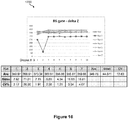
- Figure 10 also shows a table that includes for each of the seven runs (1) the average pre-dispense impedance value of the 10 droplets, (2) the standard deviation, and (3) the percent capacitance-voltage (CV%).
- FIG. 11 a plot 1200 of the post-dispense impedance values at gate electrode 162 of reservoir R3 is shown with respect to the same 10 droplets. That is, 10 droplets are dispensed from reservoir R3 of droplet actuator 100. As each of the 10 droplets is transported off of the gate electrode 162 of reservoir R3 an impedance measurement is acquired.
- Figure 11 also shows a table that includes for each of the seven runs (1) the average post-dispense impedance value of the 10 droplets, (2) the standard deviation, and (3) the CV%.
- a bar graph 1300 shows a plot of the delta Z values of gate electrode 162 of reservoir R3. That is, bar graph 1300 shows the difference (called delta Z) between the pre-dispense impedance values of bar graph 1100 of Figure 10 and the post-dispense impedance values of bar graph 1200 of Figure 11 .
- Figure 12 also shows a table that includes for each of the seven runs (1) the average delta Z value, (2) the standard deviation of the delta Z values, and (3) the CV% of the delta Z values. Additionally, the table shows the average delta Z value of all runs, the standard deviation of the delta Z value of all runs, and the CV% of the delta Z value of all runs.
- a plot 1400 of the pre-dispense impedance values at reservoir R6 is shown with respect to 10 droplets. That is, 10 droplets are dispensed from reservoir R6 of droplet actuator 100 and an impedance measurement is taken on reservoir electrode 120f of reservoir R6 just prior to the dispensing of each droplet.
- a plot 1450 of the post-dispense impedance values at reservoir R6 is shown with respect to the same 10 droplets. That is, when the 10 droplets are dispensed from reservoir R6 of droplet actuator 100, an impedance measurement is taken on reservoir electrode 120f of reservoir R6 just after the dispensing of each droplet.
- seven runs of pre-dispense impedance values and post-dispense impedance values are collected. The seven runs may include one or more instances of droplet actuator 100.
- a plot 1500 of the pre-dispense impedance values at gate electrode 162 of reservoir R6 is shown with respect to 10 droplets. That is, 10 droplets are dispensed from reservoir R6 of droplet actuator 100. As each droplet passes atop the gate electrode 162 of reservoir R6 an impedance measurement is acquired.
- Figure 14 also shows a table that includes for each of the seven runs (1) the average pre-dispense impedance value of the 10 droplets, (2) the standard deviation, and (3) the CV%.
- FIG. 15 a plot 1600 of the post-dispense impedance values at gate electrode 162 of reservoir R6 is shown with respect to the same 10 droplets. That is, 10 droplets are dispensed from reservoir R6 of droplet actuator 100. As each of the 10 droplets is transported off of the gate electrode 162 of reservoir R6 an impedance measurement is acquired.
- Figure 15 also shows a table that includes for each of the seven runs (1) the average post-dispense impedance value of the 10 droplets, (2) the standard deviation, and (3) the CV%.
- a bar graph 1700 shows a plot of the delta Z values of gate electrode 162 of reservoir R6. That is, bar graph 1700 shows the difference (called delta Z) between the pre-dispense impedance values of plot 1500 of Figure 14 and the post-dispense impedance values of plot 1600 of Figure 15 .
- Figure 16 also shows a table that includes for each of the seven runs (1) the average delta Z value, (2) the standard deviation of the delta Z values, and (3) the CV% of the delta Z values. Additionally, the table shows the average delta Z value of all runs, the standard deviation of the delta Z value of all runs, and the CV% of the delta Z value of all runs.
- temperature and/or droplet size may have an effect on the impedance measurements.
- the impedance sensing circuit that is used with a droplet actuator may utilize an impedance signal that is superimposed on a reference voltage.
- the reference voltage source is typically a switching power supply, which is a high voltage AC power supply for providing the electrowetting voltage (e.g., about 300 volts) to the electrodes of a droplet actuator.
- the stability of the high voltage AC power supply is critical because it is used as the impedance reference measurement voltage.
- switching power supplies may be noisy. For example, in a droplet actuator application, a ripple voltage of about 1 to about 3 volts may be present on the about 300V output.
- the impedance sensing circuit of the present invention provides a novel approach that does not rely on a voltage regulator to ensure stability of the high voltage AC power supply during impedance detection operations.
- the impedance sensing circuit includes an electrowetting voltage suppression mechanism for reducing noise during impedance detection operations, which is described with reference to Figures 17 and 18 .
- FIG 17 illustrates a schematic diagram of an example of an impedance sensing circuit 1800 of a droplet actuator that includes an electrowetting voltage suppression mechanism for reducing noise.
- Impedance sensing circuit 1800 may include a power supply (PS) 1810.
- PS 1810 provides the electrowetting voltage source that is needed to perform droplet operations.
- PS 1810 is a 300VAC power supply.
- Impedance sensing circuit 1800 may also include an impedance sensing system 1812.
- Impedance sensing system 1812 includes an excitation portion for generating an excitation signal and a detection portion for processing the return signal.
- the excitation signal of impedance sensing system 1812 is superimposed on the output of PS 1810 via, for example, a voltage adder 1814.
- the output of voltage adder 1814 may be selectively connected to any electrode of a droplet actuator.
- Figure 17 shows the output of voltage adder 1814 selectively connected to any reservoir electrode 120, sample reservoir electrode 122, and/or any droplet operations electrode 124 of droplet actuator 100 of Figures 1 , 2 , and 3 .
- the return path (with respect to the electrodes) to the detection portion of impedance sensing system 1812 is the electrical ground plane of the top substrate, such as top substrate 112 of droplet actuator 100.
- An aspect of the impedance sensing circuit 1800 of the invention is that it also includes a mechanism for suppressing the output of PS 1810 during impedance detection operations, thereby reducing, preferably entirely eliminating, noise on the output of PS 1810. In this way, the accuracy and/or reliability of impedance measurements taken by impedance sensing system 1812 may be improved.
- the switching action of PS 1810 which is the source of the noise, is suppressed (i.e., stopped) during impedance detection operations.
- Impedance sensing circuit 1800 includes a SUPPRESS signal that feeds the control of PS 1810 for disabling the switching action thereof during impedance detection operations. More details of the suppression mechanism of the invention are described with reference to Figure 18 .
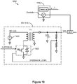
- FIG 18 illustrates a schematic diagram showing more details of impedance sensing circuit 1800 of Figure 17 that includes the electrowetting voltage suppression mechanism.
- PS 1810 includes a direct current (DC) power source 1820, a transformer T1, and a switching circuit 1822.
- DC power source 1820 and switching circuit 1822 are arranged in relation to the primary of transformer T1.
- Switching circuit 1822 may include any solid state switch device, such as an NMOS switch. In one example, the solid state switch device may be toggled off and on by a square wave from an oscillator (not shown). Switching circuit 1822 is used to develop a low voltage AC signal at the primary of transformer T1.
- a standard rectifier circuit at the secondary of transformer T1 provides an output voltage (VAC) that is a higher voltage than the input voltage.
- PS 1810 also includes a tank capacitor C1 at VAC (i.e., at the secondary of transformer T1).
- a feedback loop is provided from VAC back to switching circuit 1822.
- the SUPPRESS signal feeds switching circuit 1822 of PS 1810. For example, when the SUPPRESS signal is active the switching action of the solid state switch device of PS 1810 is stopped. In one example, during impedance detection operations, the SUPPRESS signal is used to stop the switching action of PS 1810 for several milliseconds while the impedance measurements are taking place. Stopping the switching action reduces, preferably entirely eliminates, any noise (i.e., voltage ripple) on the output of PS 1810. At the same time, tank capacitor C1 stores the charge at the output of PS 1810. In this way, the output voltage of PS 1810 is maintained while the switching action of PS 1810 is being suppressed via the SUPPRESS signal. Once impedance measurements are complete, the SUPPRESS signal may be deactivated and the normal operation of PS 1810 resumes.
- the SUPPRESS signal may be deactivated and the normal operation of PS 1810 resumes.
- An example of a method of using impedance sensing circuit 1800 of the invention may include, but is not limited to, the following steps - (1) activate the SUPPRESS signal and, thereby, stop the switching action of PS 1810; (2) activate the excitation portion of impedance sensing system 1812 and, thereby, generate an excitation signal to any one or more electrodes of interest; (3) process the return signal(s) using the detection portion of impedance sensing system 1812; (4) correlate the impedance measurements to the presence and/or absence of fluid at the one or more electrodes of interest; (5) deactivate the excitation portion of impedance sensing system 1812; and (6) deactivate the SUPPRESS signal and, thereby, resume normal operation of PS 1810.
- FIG 19 illustrates a schematic diagram of a detection circuit 2000 of an impedance sensing system that includes a feature for logging a saturation condition of the response signal.
- detection circuit 2000 may be the detection portion of impedance sensing system 1812 of Figure 17 .
- Detection circuit 2000 may include, for example, a current-to-voltage (I/V) converter 2010 and an analog-to-digital (A/D) converter 2012.
- I/V converter 2010 e.g., an operational amplifier (op amp) arrangement
- op amp operational amplifier
- A/D converter 2012 converts the voltage level to digital data and, in particular, to MAGNITUDE and PHASE data to be processed.
- Figure 20 illustrates an example of an excitation plot 2100 in relation to a response plot 2105 of an impedance sensing system. Further, response plot 2105 of Figure 20 shows both a response non-saturation condition and a response saturation condition.
- Excitation plot 2100 of Figure 20 shows a plot of the excitation signal voltage vs. time.
- excitation plot 2100 shows a plot of an excitation signal 2110, which is, for example, a sign wave that has a certain frequency and amplitude.
- Response plot 2105 of Figure 20 shows a plot of the response signal current vs. time.
- response plot 2105 shows a plot of a response signal 2120, which is, for example, a sign wave that has a certain frequency and amplitude.
- Response signal 2120 is an example of a signal at the input of I/V converter 2010.
- A/D converter 2012 One output of A/D converter 2012 is the relative phase ( ⁇ ), which is the difference in phase between, for example, excitation signal 2110 of excitation plot 2100 and response signal 2120 of response plot 2105. Referring to Figure 19 , this may be called PHASE data.
- Another output of A/D converter 2012 is peak-to-peak amplitude of, for example, response signal 2120 of response plot 2105. Referring to Figure 19 , this may be called MAGNITUDE data.
- response signal 2120 of response plot 2105 is an example of a response signal that is in a non-saturation condition.
- response plot 2105 also shows a plot of a response signal 2122, which is an example of a response signal that is in a saturation condition with respect to I/V converter 2010.
- a V-MAX and a V-MIN voltage is associated with I/V converter 2010. Any response signal, such as response signal 2122, reaching and/or exceeding the V-MAX and/or V-MIN thresholds is in saturation (e.g., response signal 2122 shown flattened out at V-MAX and V-MIN).
- detection circuit 2000 includes a feature for logging a saturation condition of the response signal during any impedance detection operation.
- the output of I/V converter 2010 feeds a pair of comparators.
- the output of I/V converter 2010 is connected to the positive input of a comparator 2014 and to the negative input of a comparator 2016.
- a voltage V1 is provided at the negative input of comparator 2014.
- a voltage V2 is provided at the positive input of comparator 2016.
- V1 may be set just slightly above V-MIN and V2 may be set just slightly below V-MAX (see response plot 2105 of Figure 20 ).
- the outputs of comparator 2014 and comparator 2016 feed an OR gate 2018.
- the output of OR gate 2018 feeds a latch 2020.
- the output of latch 2020 provides a saturation FLAG signal. If the response signal (e.g., response signal 2122 of response plot 2105 of Figure 20 ) exceeds V1 or V2, the output of at least one of comparator 2014 and comparator 2016 transitions to a logic high. This causes the output of OR gate 2018 to also go high and sets latch 2020, which means the FLAG signal is active indicating that a saturation condition is present.
- latch 2020 may be reset. However, at the end of any impedance detection operation, the state of the FLAG signal is read to determine whether a saturation condition occurred. In this way, the impedance detection operation does not depend on the digital MAGNITUDE and PHASE data alone to determine whether a saturation condition has occurred.
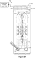
- Figure 21 illustrates a top down view of droplet actuator 100 of Figure 1 that further includes an oil sensing electrode.
- An impedance detection operation of the oil sensing electrode may be used to verify that the gap of the droplet actuator is fully filled with filler oil.
- patterned on the end of bottom substrate 110 that is nearest detection electrode 135 is an oil sensing electrode 2210.
- a fluid path 2212 that leads to oil sensing electrode 2210 is provided in gasket 114. In this way a small on-actuator fluid reservoir is created at oil sensing electrode 2210.
- filler oil may be injected into the end of droplet actuator 100 that is opposite oil sensing electrode 2210. Therefore, oil sensing electrode 2210 is the last location to fill with oil.
- oil sensing electrode 2210 may be monitored for the presence of oil thereon.
- filler oil may be injected into the gap of droplet actuator 100 using input port 128 and/or input port 130 of sample reservoir R7. The filler oil then flows in the direction from sample reservoir R7 to oil sensing electrode 2210 in order to fill the active area of droplet actuator 100.
- oil sensing electrode 2210 is monitored using, for example, impedance sensing system 170.
- an oil sensing electrode such as oil sensing electrode 2210, provides a way to use impedance detection to ensure that the active area of droplet actuator 100 is fully filled with oil, according to the present invention.
- Figure 22 illustrates a top view of a portion of a droplet actuator 2300 in which the input port of an on-actuator reservoir is not directly over any portion of the reservoir electrode.
- droplet actuator 2300 includes a reservoir electrode 2310 that has a loading port 2312 in the top substrate (not shown) that is not directly over any portion of reservoir electrode 2310.
- a reservoir boundary 2314 is shown that defines the size, shape, and/or volume of the on-actuator reservoir.
- the reservoir boundary 2314 may be established by, for example, a gasket, features in the top substrate, features in the bottom substrate, and/or any combinations thereof.
- a fluid path 2316 is present from loading port 2312 to reservoir electrode 2310.
- loading port 2312 is not directly over reservoir electrode 2310 and fluid path 2316 is provided by which fluid may flow to the reservoir electrode 2310 for filling. In this way, the variability of the fluid volume at the reservoir may be reduced, preferably entirely eliminated, as indicated by less impedance measurement variability during filling and/or use.
- FIGS 23A and 23B illustrate top views of an electrode arrangement 2400 and an electrode arrangement 2420, respectively, which are examples of electrode configurations for helping to detect whether a sample reservoir is fully loaded.
- This embodiment of the invention provides a separate electrode at the fringe of the primary storage reservoir for measuring impedance in order to verify that the reservoir is fully loaded (i.e., not underloaded).
- electrode arrangement 2400 of Figure 23A includes a reservoir electrode 2410.
- Reservoir electrode 2410 may be associated with an on-actuator reservoir.
- One side of reservoir electrode 2410 feeds a line, path, and/or array of droplet operations electrodes 2412 (e.g., electrowetting electrodes).
- An elongated impedance electrode 2414 is provided along the side of reservoir electrode 2410 that is opposite the droplet operations electrodes 2412.
- the impedance electrode 2414 is a separate electrode at the fringe of the primary storage reservoir. Using impedance detection, one may verify that liquid is atop impedance electrode 2414, which provides assurance that the associated reservoir is fully loaded.
- electrode arrangement 2420 of Figure 23B includes a reservoir electrode 2422.
- Reservoir electrode 2422 may be associated with an on-actuator reservoir.
- One side of reservoir electrode 2422 feeds a line, path, and/or array of droplet operations electrodes 2424 (e.g., electrowetting electrodes).
- a triangular-shaped impedance electrode 2426 is provided at one of the corners of reservoir electrode 2422 that is opposite the droplet operations electrodes 2424.
- the impedance electrode 2426 is a separate electrode at the fringe of the primary storage reservoir. Using impedance detection, one may verify that liquid is atop impedance electrode 2426, which provides assurance that the associated reservoir is fully loaded. While Figures 23A and 23B describe examples of a single impedance electrode at one location with respect to the primary storage reservoir, Figures 24A, 24B, and 24C describe examples of impedance electrodes at multiple locations of the primary storage reservoir.
- Figures 24A, 24B, and 24C illustrate top views of an electrode arrangement 2500, an electrode arrangement 2520, and an electrode arrangement 2540, respectively, which are more examples of electrode configurations for helping to detect whether a sample reservoir is fully loaded.
- electrode arrangement 2500 of Figure 24A includes a reservoir electrode 2510.
- Reservoir electrode 2510 may be associated with an on-actuator reservoir.
- One side of reservoir electrode 2510 feeds a line, path, and/or array of droplet operations electrodes 2512 (e.g., electrowetting electrodes).
- a U-shaped impedance electrode 2514 is provided along the three sides of reservoir electrode 2510 that do not feed droplet operations electrodes 2512. Again, the impedance electrode 2514 is a separate electrode at the fringe of the primary storage reservoir. Using impedance detection, one may verify that liquid is atop impedance electrode 2514, which provides assurance that the associated reservoir is fully loaded.
- electrode arrangement 2520 of Figure 24B includes a reservoir electrode 2522.
- Reservoir electrode 2522 may be associated with an on-actuator reservoir.
- One side of reservoir electrode 2510 feeds a line, path, and/or array of droplet operations electrodes 2524 (e.g., electrowetting electrodes).
- Reservoir electrode 2522 is flanked by two elongated impedance electrodes 2526 (e.g., impedance electrodes 2526a and 2525b). Again, impedance electrodes 2526a and 2525b are separate electrodes at the fringe of the primary storage reservoir. Using impedance detection, one may verify that liquid is atop impedance electrodes 2526a and 2525b, which provides assurance that the associated reservoir is fully loaded.
- electrode arrangement 2540 of Figure 24C includes a reservoir electrode 2542.
- Reservoir electrode 2542 may be associated with an on-actuator reservoir.
- One side of reservoir electrode 2542 feeds a line, path, and/or array of droplet operations electrodes 2544 (e.g., electrowetting electrodes).
- four triangular-shaped impedance electrodes 2546 e.g., impedance electrodes 2546a, 2546b, 2546c, and 2546d
- impedance electrodes 2546a, 2546b, 2546c, and 2546d are separate electrodes at the fringe of the primary storage reservoir.
- impedance detection one may verify that liquid is atop impedance electrodes 2546a, 2546b, 2546c, and 2546d, which provides assurance that the associated reservoir is fully loaded.
- aspects of the invention may be embodied as a method, system, computer readable medium, and/or computer program product.
- aspects of the invention may take the form of hardware embodiments, software embodiments (including firmware, resident software, micro-code, etc.), or embodiments combining software and hardware aspects that may all generally be referred to herein as a "circuit,” “module” or “system.”
- the methods of the invention may take the form of a computer program product on a computer-usable storage medium having computer-usable program code embodied in the medium.
- the computer-usable or computer-readable medium may be, for example but not limited to, an electronic, magnetic, optical, electromagnetic, infrared, or semiconductor system, apparatus, device, or propagation medium.
- the computer readable medium may include transitory and/or non-transitory embodiments.
- the computer-readable medium would include some or all of the following: an electrical connection having one or more wires, a portable computer diskette, a hard disk, a random access memory (RAM), a read-only memory (ROM), an erasable programmable read-only memory (EPROM or Flash memory), an optical fiber, a portable compact disc read-only memory (CD-ROM), an optical storage device, a transmission medium such as those supporting the Internet or an intranet, or a magnetic storage device.
- RAM random access memory
- ROM read-only memory
- EPROM or Flash memory erasable programmable read-only memory
- CD-ROM compact disc read-only memory
- CD-ROM compact disc read-only memory
- a transmission medium such as those supporting the Internet or an intranet, or a magnetic storage device.
- the computer-usable or computer-readable medium could even be paper or another suitable medium upon which the program is printed, as the program can be electronically captured, via, for instance, optical scanning of the paper or other medium, then compiled, interpreted, or otherwise processed in a suitable manner, if necessary, and then stored in a computer memory.
- a computer-usable or computer-readable medium may be any medium that can contain, store, communicate, propagate, or transport the program for use by or in connection with the instruction execution system, apparatus, or device.
- Program code for carrying out operations of the invention may be written in an object oriented programming language such as Java, Smalltalk, C++ or the like. However, the program code for carrying out operations of the invention may also be written in conventional procedural programming languages, such as the "C" programming language or similar programming languages.
- the program code may be executed by a processor, application specific integrated circuit (ASIC), or other component that executes the program code.
- the program code may be simply referred to as a software application that is stored in memory (such as the computer readable medium discussed above).
- the program code may cause the processor (or any processor-controlled device) to produce a graphical user interface ("GUI").
- GUI graphical user interface
- the graphical user interface may be visually produced on a display device, yet the graphical user interface may also have audible features.
- the program code may operate in any processor-controlled device, such as a computer, server, personal digital assistant, phone, television, or any processor-controlled device utilizing the processor and/or a digital signal processor.
- the program code may locally and/or remotely execute.
- the program code for example, may be entirely or partially stored in local memory of the processor-controlled device.
- the program code may also be at least partially remotely stored, accessed, and downloaded to the processor-controlled device.
- a user's computer for example, may entirely execute the program code or only partly execute the program code.
- the program code may be a stand-alone software package that is at least partly on the user's computer and/or partly executed on a remote computer or entirely on a remote computer or server. In the latter scenario, the remote computer may be connected to the user's computer through a communications network.
- the invention may be applied regardless of networking environment.
- the communications network may be a cable network operating in the radio-frequency domain and/or the Internet Protocol (IP) domain.
- IP Internet Protocol
- the communications network may also include a distributed computing network, such as the Internet (sometimes alternatively known as the "World Wide Web"), an intranet, a local-area network (LAN), and/or a wide-area network (WAN).
- the communications network may include coaxial cables, copper wires, fiber optic lines, and/or hybrid-coaxial lines.
- the communications network may even include wireless portions utilizing any portion of the electromagnetic spectrum and any signaling standard (such as the IEEE 802 family of standards, GSM/CDMA/TDMA or any cellular standard, and/or the ISM band).
- the communications network may even include powerline portions, in which signals are communicated via electrical wiring.
- the invention may be applied to any wireless/wireline communications network, regardless of physical componentry, physical configuration, or communications standard(s).
- the program code may also be stored in a computer-readable memory that can direct the processor, computer, or other programmable data processing apparatus to function in a particular manner, such that the program code stored in the computer-readable memory produce or transform an article of manufacture including instruction means which implement various aspects of the method steps.
- the program code may also be loaded onto a computer or other programmable data processing apparatus to cause a series of operational steps to be performed to produce a processor/computer implemented process such that the program code provides steps for implementing various functions/acts specified in the methods of the invention.
Landscapes
- Chemical & Material Sciences (AREA)
- Health & Medical Sciences (AREA)
- Dispersion Chemistry (AREA)
- Analytical Chemistry (AREA)
- General Health & Medical Sciences (AREA)
- Chemical Kinetics & Catalysis (AREA)
- Hematology (AREA)
- Clinical Laboratory Science (AREA)
- General Physics & Mathematics (AREA)
- Physics & Mathematics (AREA)
- Life Sciences & Earth Sciences (AREA)
- Biochemistry (AREA)
- Electrochemistry (AREA)
- Immunology (AREA)
- Pathology (AREA)
- Physical Or Chemical Processes And Apparatus (AREA)
- Apparatus Associated With Microorganisms And Enzymes (AREA)
- Automatic Analysis And Handling Materials Therefor (AREA)
- Particle Formation And Scattering Control In Inkjet Printers (AREA)
- Investigating Or Analyzing Materials By The Use Of Electric Means (AREA)
Claims (13)
- Un procédé pour mesurer l'impédance d'une électrode (120, 122, 124) dans un actionneur de gouttelettes (100), l'actionneur de gouttelettes comprenant des électrodes agencées pour mener des opérations sur des gouttelettes par électromouillage, le procédé comprenant :(a) la production, par un bloc d'alimentation (1810), d'un signal de tension de sortie pour fournir une tension d'électromouillage aux électrodes (120, 122, 124) de l'actionneur de gouttelettes (100) ;(b) la superposition d'un signal d'excitation (2110) sur le signal de tension de sortie afin de produire un signal superposé ;(c) la connexion du signal superposé sur une électrode (120, 122, 124) dans l'actionneur de gouttelettes (100) ;(d) durant des opérations de détection d'impédance pour détecter une impédance de l'électrode (120, 122, 124), l'arrêt du signal de tension de sortie en provenance du bloc d'alimentation (1810) ; et(e) la mesure de l'impédance de l'électrode (120, 122, 124) produite par le signal d'excitation, où l'impédance indique la présence ou l'absence de liquide au niveau de l'électrode (120, 122, 124).
- Le procédé de la revendication 1, où la superposition du signal d'excitation (2110) comprend l'ajout du signal d'excitation (2110) au signal de tension de sortie.
- Le procédé de la revendication 1, où l'arrêt du signal de tension de sortie comprend la désactivation d'une action de commutation du bloc d'alimentation (1810).
- Le procédé de la revendication 1, où l'arrêt du signal de tension de sortie comprend la désactivation du bloc d'alimentation (1810).
- Le procédé de la revendication 1, comprenant en outre la détermination d'une saturation de l'impédance.
- Le procédé de la revendication 1, comprenant en outre :(a) l'injection du liquide dans l'actionneur de gouttelettes (100) ; et(b) l'arrêt de l'injection lorsque l'impédance indique que le liquide s'est écoulé jusqu'à l'électrode (120, 122, 124).
- Le procédé de la revendication 1, comprenant en outre :(a) l'injection du liquide dans un espace dans l'actionneur de gouttelettes (100) ; et(b) l'arrêt de l'injection lorsque l'impédance indique que le liquide s'est écoulé jusqu'à l'électrode (120, 122, 124).
- Le procédé de la revendication 1, comprenant en outre :(a) l'injection du liquide dans un réservoir (R1 à R7) dans l'actionneur de gouttelettes (100) ; et(b) l'arrêt de l'injection lorsque l'impédance indique que le liquide s'est écoulé jusqu'à l'électrode (120, 122, 124).
- Le procédé de la revendication 1, comprenant en outre :(a) l'injection du liquide afin de remplir un réservoir (R1 à R7) dans l'actionneur de gouttelettes (100) ; et(b) l'arrêt de l'injection lorsque l'impédance indique que le liquide s'est écoulé du réservoir (R1 à R7) jusqu'à l'électrode (120, 122, 124).
- Le procédé de la revendication 1, comprenant en outre :(a) l'établissement d'une trajectoire de fluide dans l'actionneur de gouttelettes (100) allant d'un orifice d'entrée (128, 130, 134) à un réservoir (R1 à R7) à l'électrode (120, 122, 124);(b) l'injection du liquide à travers l'orifice d'entrée (128, 130, 134) afin de remplir le réservoir (R1 à R7) ; et(c) l'arrêt de l'injection lorsque l'impédance indique que le liquide s'est écoulé jusqu'à l'électrode (120, 122, 124).
- Le procédé de la revendication 1, comprenant en outre :(a) l'agencement d'un orifice d'entrée (128, 130, 134) à l'extérieur d'une limite d'un réservoir (R1 à R7) dans l'actionneur de gouttelettes (100) ;(b) la formation d'une trajectoire de fluide allant de l'orifice d'entrée (128, 130, 134) au réservoir (R1 à R7) à l'électrode (120, 122, 124) ;(c) l'injection du liquide à travers l'orifice d'entrée (128, 130, 134) afin de remplir le réservoir (R1 à R7) ; et(d) l'arrêt de l'injection lorsque l'impédance indique que le liquide s'est écoulé jusqu'à l'électrode (120, 122, 124).
- Un système pour mesurer l'impédance d'une électrode (120, 122, 124) dans un actionneur de gouttelettes (100), l'actionneur de gouttelettes comprenant des électrodes agencées pour mener des opérations sur des gouttelettes par électromouillage, le système comprenant :(a) un processeur ;(b) de la mémoire ; et(c) un code stocké dans la mémoire qui, lorsqu'il est exécuté, amène le processeur au moins à mettre en oeuvre le procédé de la revendication 1.
- Le système de la revendication 12, où ledit code, lorsqu'il est exécuté, amène le processeur au moins à mettre en oeuvre le procédé de l'une quelconque des revendications 2 à 4 et 6 à 11.
Priority Applications (1)
| Application Number | Priority Date | Filing Date | Title |
|---|---|---|---|
| EP13192679.2A EP2711079B1 (fr) | 2011-05-09 | 2012-05-08 | Détection à l'aide de l'impédance de rétroaction microfluidique |
Applications Claiming Priority (2)
| Application Number | Priority Date | Filing Date | Title |
|---|---|---|---|
| US201161483827P | 2011-05-09 | 2011-05-09 | |
| PCT/US2012/036949 WO2012154745A2 (fr) | 2011-05-09 | 2012-05-08 | Rétroaction microfluidique utilisant une détection d'impédance |
Related Child Applications (2)
| Application Number | Title | Priority Date | Filing Date |
|---|---|---|---|
| EP13192679.2A Division-Into EP2711079B1 (fr) | 2011-05-09 | 2012-05-08 | Détection à l'aide de l'impédance de rétroaction microfluidique |
| EP13192679.2A Division EP2711079B1 (fr) | 2011-05-09 | 2012-05-08 | Détection à l'aide de l'impédance de rétroaction microfluidique |
Publications (3)
| Publication Number | Publication Date |
|---|---|
| EP2707131A2 EP2707131A2 (fr) | 2014-03-19 |
| EP2707131A4 EP2707131A4 (fr) | 2014-11-19 |
| EP2707131B1 true EP2707131B1 (fr) | 2019-04-24 |
Family
ID=47139943
Family Applications (2)
| Application Number | Title | Priority Date | Filing Date |
|---|---|---|---|
| EP12781709.6A Active EP2707131B1 (fr) | 2011-05-09 | 2012-05-08 | Rétroaction microfluidique utilisant une détection d'impédance |
| EP13192679.2A Active EP2711079B1 (fr) | 2011-05-09 | 2012-05-08 | Détection à l'aide de l'impédance de rétroaction microfluidique |
Family Applications After (1)
| Application Number | Title | Priority Date | Filing Date |
|---|---|---|---|
| EP13192679.2A Active EP2711079B1 (fr) | 2011-05-09 | 2012-05-08 | Détection à l'aide de l'impédance de rétroaction microfluidique |
Country Status (4)
| Country | Link |
|---|---|
| US (2) | US9188615B2 (fr) |
| EP (2) | EP2707131B1 (fr) |
| CA (1) | CA2833897C (fr) |
| WO (1) | WO2012154745A2 (fr) |
Families Citing this family (47)
| Publication number | Priority date | Publication date | Assignee | Title |
|---|---|---|---|---|
| EP2109774B1 (fr) | 2007-02-15 | 2018-07-04 | Advanced Liquid Logic, Inc. | Détection de capacité sur un actuateur goutte |
| WO2012154745A2 (fr) | 2011-05-09 | 2012-11-15 | Advanced Liquid Logic, Inc. | Rétroaction microfluidique utilisant une détection d'impédance |
| JP6107054B2 (ja) * | 2012-10-30 | 2017-04-05 | セイコーエプソン株式会社 | 液体輸送装置 |
| DK3098298T3 (da) * | 2014-01-24 | 2020-05-04 | Japan Science & Tech Agency | Indretning til podning og dyrkning af celler |
| US11192107B2 (en) * | 2014-04-25 | 2021-12-07 | Berkeley Lights, Inc. | DEP force control and electrowetting control in different sections of the same microfluidic apparatus |
| EP3224053A1 (fr) * | 2014-11-25 | 2017-10-04 | Hewlett-Packard Development Company, L.P. | Composant de propulsion de liquide |
| WO2016122565A1 (fr) | 2015-01-30 | 2016-08-04 | Hewlett-Packard Development Company, L.P. | Détection microfluidique |
| KR20160120416A (ko) * | 2015-04-08 | 2016-10-18 | 인제대학교 산학협력단 | 분리 가능한 복수의 패널을 포함하는 미세 입자 분리 장치 어셈블리 |
| UA128328C2 (uk) | 2015-04-22 | 2024-06-12 | Олтріа Клайєнт Сервісиз Ллк | Капсула для електронного пристрою для вироблення пари і електронний пристрій для вироблення пари, що містить таку капсулу |
| USD874720S1 (en) | 2015-04-22 | 2020-02-04 | Altria Client Services, Llc | Pod for an electronic vaping device |
| USD1052163S1 (en) | 2015-04-22 | 2024-11-19 | Altria Client Services Llc | Electronic vaping device |
| US10104913B2 (en) | 2015-04-22 | 2018-10-23 | Altria Client Services Llc | Pod assembly, dispensing body, and E-vapor apparatus including the same |
| USD980507S1 (en) | 2015-04-22 | 2023-03-07 | Altria Client Services Llc | Electronic vaping device |
| USD874059S1 (en) | 2015-04-22 | 2020-01-28 | Altria Client Servies Llc | Electronic vaping device |
| US10671031B2 (en) | 2015-04-22 | 2020-06-02 | Altria Client Services Llc | Body gesture control system for button-less vaping |
| US10064432B2 (en) | 2015-04-22 | 2018-09-04 | Altria Client Services Llc | Pod assembly, dispensing body, and E-vapor apparatus including the same |
| CN108026494A (zh) | 2015-06-05 | 2018-05-11 | 米罗库鲁斯公司 | 限制蒸发和表面结垢的空气基质数字微流控装置和方法 |
| US10695762B2 (en) | 2015-06-05 | 2020-06-30 | Miroculus Inc. | Evaporation management in digital microfluidic devices |
| US20190217300A1 (en) * | 2015-10-22 | 2019-07-18 | Illumina, Inc. | Filler fluid for fluidic devices |
| US9513220B1 (en) * | 2015-12-29 | 2016-12-06 | International Business Machines Corporation | On-chip molecule fluorescence detection |
| CN109715781A (zh) | 2016-08-22 | 2019-05-03 | 米罗库鲁斯公司 | 用于数字微流控设备中的并行液滴控制的反馈系统 |
| US11331226B2 (en) * | 2016-11-18 | 2022-05-17 | Vener8 Technologies | Biofluids detection and notification system and method |
| CN110383061A (zh) | 2016-12-28 | 2019-10-25 | 米罗库鲁斯公司 | 数字微流控设备和方法 |
| CN106814110B (zh) * | 2017-01-05 | 2020-11-06 | 华中科技大学 | 一种可拉伸半导体电阻式柔性气体传感器及其制备方法 |
| US11623219B2 (en) | 2017-04-04 | 2023-04-11 | Miroculus Inc. | Digital microfluidics apparatuses and methods for manipulating and processing encapsulated droplets |
| US11059043B2 (en) * | 2017-04-19 | 2021-07-13 | The Johns Hopkins University | Impedance based feedback control of microfluidic valves |
| US10730048B2 (en) * | 2017-06-21 | 2020-08-04 | Sharp Life Science (Eu) Limited | EWOD device with holdback feature for fluid loading |
| EP3658908B1 (fr) | 2017-07-24 | 2025-11-12 | Integra Biosciences AG | Systèmes microfluidiques numériques et procédés à dispositif de collecte de plasma intégré |
| CA3073058A1 (fr) | 2017-09-01 | 2019-03-07 | Miroculus Inc. | Dispositifs microfluidiques numeriques et leurs procedes d'utilisation |
| CN108226261A (zh) * | 2018-01-02 | 2018-06-29 | 京东方科技集团股份有限公司 | 一种电化学检测芯片及其检测方法 |
| WO2019226919A1 (fr) | 2018-05-23 | 2019-11-28 | Miroculus Inc. | Contrôle de l'évaporation dans la microfluidique numérique |
| JP7586711B2 (ja) * | 2018-06-05 | 2024-11-19 | クロノス ヘルス, インク. | 液体移動を制御し、生体試料を分析するためのデバイス、カートリッジ、およびセンサ |
| CN108988121B (zh) * | 2018-07-25 | 2020-01-07 | 北京小米移动软件有限公司 | 光学装置及设备 |
| US20210237059A1 (en) * | 2018-08-09 | 2021-08-05 | Hewlett-Packard Development Company, L.P. | Microfluidic devices with impedance setting to set backpressure |
| US11506592B2 (en) | 2018-10-19 | 2022-11-22 | Rutgers, The State University Of New Jersey | Wearable impedance cytometer |
| EP3917670A4 (fr) | 2019-01-31 | 2022-11-02 | Miroculus Inc. | Compositions anti-encrassement et procédés de manipulation et de traitement de gouttelettes encapsulées |
| US12582991B2 (en) | 2019-02-28 | 2026-03-24 | Integra Biosciences Ag | Digital microfluidics devices and methods of using them |
| CN209829010U (zh) * | 2019-03-01 | 2019-12-24 | 南京岚煜生物科技有限公司 | 一种多通道微流体凝血检测芯片 |
| CN114206499B (zh) | 2019-04-08 | 2024-10-08 | 米罗库鲁斯公司 | 多盒式数字微流控装置和使用方法 |
| US11524298B2 (en) | 2019-07-25 | 2022-12-13 | Miroculus Inc. | Digital microfluidics devices and methods of use thereof |
| MY200464A (en) * | 2020-04-30 | 2023-12-27 | Silterra Malaysia Sdn Bhd | A device for determining information of a substance in a matter |
| CN113671359B (zh) * | 2020-05-15 | 2024-08-13 | 京东方科技集团股份有限公司 | 数字微流控制芯片及其故障检测方法 |
| WO2021232006A1 (fr) | 2020-05-15 | 2021-11-18 | Baebies, Inc. | Techniques analytiques microfluidiques numériques |
| TWI854167B (zh) * | 2020-12-14 | 2024-09-01 | 國立中央大學 | 複合式細胞成像與生化檢測晶片及其使用方法 |
| KR102486062B1 (ko) * | 2021-04-05 | 2023-01-06 | 인제대학교 산학협력단 | 액적의 크기 제어가 가능한 능동형 액적 생성장치, 이를 이용한 액적 크기 제어방법 및 액적 생성 자가진단 장치 |
| CN113457758B (zh) * | 2021-07-14 | 2023-05-23 | 浙江理工大学 | 一种导纳式测量出汗率的微流控通道 |
| US11772093B2 (en) | 2022-01-12 | 2023-10-03 | Miroculus Inc. | Methods of mechanical microfluidic manipulation |
Citations (2)
| Publication number | Priority date | Publication date | Assignee | Title |
|---|---|---|---|---|
| US20070275415A1 (en) * | 2006-04-18 | 2007-11-29 | Vijay Srinivasan | Droplet-based affinity assays |
| US20100041086A1 (en) * | 2007-03-22 | 2010-02-18 | Advanced Liquid Logic, Inc. | Enzyme Assays for a Droplet Actuator |
Family Cites Families (242)
| Publication number | Priority date | Publication date | Assignee | Title |
|---|---|---|---|---|
| DE2319175A1 (de) | 1973-04-16 | 1974-10-31 | Oxford Lab | Detail-kolbenpipette |
| US4127460A (en) | 1976-10-27 | 1978-11-28 | Desoto, Inc. | Radiation-curing aqueous coatings providing a nonadherent surface |
| US4244693A (en) | 1977-02-28 | 1981-01-13 | The United States Of America As Represented By The United States Department Of Energy | Method and composition for testing for the presence of an alkali metal |
| FR2543320B1 (fr) | 1983-03-23 | 1986-01-31 | Thomson Csf | Dispositif indicateur a commande electrique de deplacement d'un fluide |
| EP0175362A3 (fr) | 1984-09-19 | 1988-12-07 | Omron Tateisi Electronics Co. | Dispositif de détection du type capacitif |
| US5038852A (en) | 1986-02-25 | 1991-08-13 | Cetus Corporation | Apparatus and method for performing automated amplification of nucleic acid sequences and assays using heating and cooling steps |
| US4829833A (en) | 1985-11-12 | 1989-05-16 | Feller Murray F | Liquid impedance flow monitors |
| FR2599369B1 (fr) | 1986-05-30 | 1989-03-31 | Europ Propulsion | Procede de preparation de disilylmethanes |
| US4936828A (en) | 1987-06-02 | 1990-06-26 | Kophu Chiang | Liquid drop image sensor |
| US6013531A (en) | 1987-10-26 | 2000-01-11 | Dade International Inc. | Method to use fluorescent magnetic polymer particles as markers in an immunoassay |
| US5225332A (en) | 1988-04-22 | 1993-07-06 | Massachusetts Institute Of Technology | Process for manipulation of non-aqueous surrounded microdroplets |
| GB8917963D0 (en) | 1989-08-05 | 1989-09-20 | Scras | Apparatus for repeated automatic execution of a thermal cycle for treatment of biological samples |
| US5266498A (en) | 1989-10-27 | 1993-11-30 | Abbott Laboratories | Ligand binding assay for an analyte using surface-enhanced scattering (SERS) signal |
| US5181016A (en) | 1991-01-15 | 1993-01-19 | The United States Of America As Represented By The United States Department Of Energy | Micro-valve pump light valve display |
| US5498392A (en) | 1992-05-01 | 1996-03-12 | Trustees Of The University Of Pennsylvania | Mesoscale polynucleotide amplification device and method |
| WO1994008759A1 (fr) | 1992-10-16 | 1994-04-28 | Thomas Jefferson University | Procede et appareil d'execution robotique de reactions de sequencage de didesoxynucleotides de sanger |
| US5472881A (en) | 1992-11-12 | 1995-12-05 | University Of Utah Research Foundation | Thiol labeling of DNA for attachment to gold surfaces |
| US6152181A (en) | 1992-11-16 | 2000-11-28 | The United States Of America As Represented By The Secretary Of The Air Force | Microdevices based on surface tension and wettability that function as sensors, actuators, and other devices |
| EP0636413B1 (fr) | 1993-07-28 | 2001-11-14 | PE Corporation (NY) | Dispositif et procédé d'amplification d'acide nucléique |
| US5486337A (en) | 1994-02-18 | 1996-01-23 | General Atomics | Device for electrostatic manipulation of droplets |
| US6673533B1 (en) | 1995-03-10 | 2004-01-06 | Meso Scale Technologies, Llc. | Multi-array multi-specific electrochemiluminescence testing |
| US6319668B1 (en) | 1995-04-25 | 2001-11-20 | Discovery Partners International | Method for tagging and screening molecules |
| CA2176053C (fr) | 1995-05-09 | 1999-10-05 | Yoshihiro Kinoshita | Methode et appareil pour immuno-essai par agglutination |
| US6130098A (en) | 1995-09-15 | 2000-10-10 | The Regents Of The University Of Michigan | Moving microdroplets |
| DE69638321D1 (de) | 1995-10-11 | 2011-03-03 | Luminex Corp | Gleichzeitige mehrfachanalyse klinischer proben |
| US5945281A (en) | 1996-02-02 | 1999-08-31 | Becton, Dickinson And Company | Method and apparatus for determining an analyte from a sample fluid |
| EP0946749A1 (fr) | 1996-11-20 | 1999-10-06 | The Regents Of The University Of Michigan | Dispositifs microfabriques et procedes d'amplification isotherme d'acides nucleiques |
| DE19717085C2 (de) | 1997-04-23 | 1999-06-17 | Bruker Daltonik Gmbh | Verfahren und Geräte für extrem schnelle DNA-Vervielfachung durch Polymerase-Kettenreaktionen (PCR) |
| US5998224A (en) | 1997-05-16 | 1999-12-07 | Abbott Laboratories | Magnetically assisted binding assays utilizing a magnetically responsive reagent |
| US20020001544A1 (en) | 1997-08-28 | 2002-01-03 | Robert Hess | System and method for high throughput processing of droplets |
| US7214298B2 (en) | 1997-09-23 | 2007-05-08 | California Institute Of Technology | Microfabricated cell sorter |
| DE19742608C2 (de) | 1997-09-26 | 1999-09-09 | Jenoptik Jena Gmbh | Verfahren und Anordnung zur Auswertung von Laser-Doppler-Signalen |
| EP0965044B1 (fr) | 1997-11-18 | 2003-03-19 | Bio-Rad Laboratories, Inc. | Dosages immunologiques multiplex de flux, dans lesquels des particules magnetiques font office de phase solide |
| DE19822123C2 (de) | 1997-11-21 | 2003-02-06 | Meinhard Knoll | Verfahren und Vorrichtung zum Nachweis von Analyten |
| US6063339A (en) | 1998-01-09 | 2000-05-16 | Cartesian Technologies, Inc. | Method and apparatus for high-speed dot array dispensing |
| US6565727B1 (en) | 1999-01-25 | 2003-05-20 | Nanolytics, Inc. | Actuators for microfluidics without moving parts |
| US6294063B1 (en) | 1999-02-12 | 2001-09-25 | Board Of Regents, The University Of Texas System | Method and apparatus for programmable fluidic processing |
| DE60045917D1 (de) | 1999-02-23 | 2011-06-16 | Caliper Life Sciences Inc | Sequenzierung durch inkorporation |
| DE60036746T2 (de) | 1999-03-25 | 2008-07-24 | Tosoh Corp., Shinnanyo | Analysator |
| IT1309430B1 (it) | 1999-05-18 | 2002-01-23 | Guerrieri Roberto | Metodo ed apparato per la manipolazione di particelle per mezzo delladielettroforesi |
| FR2794039B1 (fr) | 1999-05-27 | 2002-05-03 | Osmooze Sa | Dispositif de formation, de deplacement et de diffusion de petites quantites calibrees de liquides |
| US6977145B2 (en) | 1999-07-28 | 2005-12-20 | Serono Genetics Institute S.A. | Method for carrying out a biochemical protocol in continuous flow in a microreactor |
| ATE412184T1 (de) | 1999-08-17 | 2008-11-15 | Luminex Corp | Verfahren zur analyse einer mehrzahl von proben verschiedenen ursprungs auf einen analyten |
| WO2001013119A1 (fr) | 1999-08-17 | 2001-02-22 | Luminex Corporation | Encapsulation de particules fluorescentes |
| US20030027204A1 (en) | 1999-09-03 | 2003-02-06 | Yokogawa Electric Corporation, A Japan Corporation | Method and apparatus for producing biochips |
| US20040209376A1 (en) | 1999-10-01 | 2004-10-21 | Surromed, Inc. | Assemblies of differentiable segmented particles |
| ATE328670T1 (de) | 1999-11-11 | 2006-06-15 | Trinity College Dublin | Vorrichtung und verfahren zur verabreichung von tropfen |
| US6432290B1 (en) | 1999-11-26 | 2002-08-13 | The Governors Of The University Of Alberta | Apparatus and method for trapping bead based reagents within microfluidic analysis systems |
| US6924792B1 (en) | 2000-03-10 | 2005-08-02 | Richard V. Jessop | Electrowetting and electrostatic screen display systems, colour displays and transmission means |
| JP3442338B2 (ja) | 2000-03-17 | 2003-09-02 | 株式会社日立製作所 | Dna分析装置、dna塩基配列決定装置、dna塩基配列決定方法、および反応モジュール |
| WO2002007503A1 (fr) | 2000-07-25 | 2002-01-31 | The Regents Of The University Of California | Micropompage par electromouillage |
| CA2314398A1 (fr) | 2000-08-10 | 2002-02-10 | Edward Shipwash | Jeux ordonnes de microechantillons et microsystemes pour l'analyse d'acides amines et le sequencage de proteines |
| US6773566B2 (en) | 2000-08-31 | 2004-08-10 | Nanolytics, Inc. | Electrostatic actuators for microfluidics and methods for using same |
| WO2002023163A1 (fr) | 2000-09-15 | 2002-03-21 | California Institute Of Technology | Dispositifs a debit transversal microfabriques et procedes associes |
| GB0023545D0 (en) | 2000-09-26 | 2000-11-08 | Xaar Technology Ltd | Droplet deposition apparatus |
| US6453928B1 (en) | 2001-01-08 | 2002-09-24 | Nanolab Ltd. | Apparatus, and method for propelling fluids |
| US7010391B2 (en) | 2001-03-28 | 2006-03-07 | Handylab, Inc. | Methods and systems for control of microfluidic devices |
| CA2442978A1 (fr) | 2001-04-04 | 2002-10-17 | Bioprocessors Corp. | Systeme et procede de distribution de liquides |
| US7211442B2 (en) | 2001-06-20 | 2007-05-01 | Cytonome, Inc. | Microfluidic system including a virtual wall fluid interface port for interfacing fluids with the microfluidic system |
| US7179423B2 (en) | 2001-06-20 | 2007-02-20 | Cytonome, Inc. | Microfluidic system including a virtual wall fluid interface port for interfacing fluids with the microfluidic system |
| US6734436B2 (en) | 2001-08-07 | 2004-05-11 | Sri International | Optical microfluidic devices and methods |
| US6995024B2 (en) | 2001-08-27 | 2006-02-07 | Sri International | Method and apparatus for electrostatic dispensing of microdroplets |
| US6777958B2 (en) | 2001-10-17 | 2004-08-17 | Delphi Technologies, Inc. | Method and apparatus for detecting a change in capacitance of a capacitive proximity sensor |
| US7148683B2 (en) | 2001-10-25 | 2006-12-12 | Intematix Corporation | Detection with evanescent wave probe |
| US20040231987A1 (en) | 2001-11-26 | 2004-11-25 | Keck Graduate Institute | Method, apparatus and article for microfluidic control via electrowetting, for chemical, biochemical and biological assays and the like |
| AU2002359508A1 (en) | 2001-11-26 | 2003-06-10 | Keck Graduate Institute | Method, apparatus and article for microfluidic control via electrowetting, for chemical, biochemical and biological assays and the like |
| US6703819B2 (en) * | 2001-12-03 | 2004-03-09 | Board Of Regents, The University Of Texas System | Particle impedance sensor |
| JP3813104B2 (ja) | 2002-03-27 | 2006-08-23 | 日本ユニカ株式会社 | 絶縁性流動体の計測装置、純度制御装置、混合度制御装置 |
| US7147763B2 (en) | 2002-04-01 | 2006-12-12 | Palo Alto Research Center Incorporated | Apparatus and method for using electrostatic force to cause fluid movement |
| MXPA04010450A (es) | 2002-04-22 | 2005-09-08 | Univ Maryland | Inhibicion antiviral de la proteina del recubrimiento capsomerico. |
| US20030203504A1 (en) * | 2002-04-26 | 2003-10-30 | John Hefti | Diffusion-based system and method for detecting and monitoring activity of biologic and chemical species |
| FR2841063B1 (fr) | 2002-06-18 | 2004-09-17 | Commissariat Energie Atomique | Dispositif de deplacement de petits volumes de liquide le long d'un micro-catenaire par des forces electrostatiques |
| JP2006507921A (ja) | 2002-06-28 | 2006-03-09 | プレジデント・アンド・フェロウズ・オブ・ハーバード・カレッジ | 流体分散のための方法および装置 |
| FR2842747B1 (fr) | 2002-07-23 | 2004-10-15 | Commissariat Energie Atomique | Procede et dispositif pour le criblage de molecules dans des cellules |
| FR2843048B1 (fr) | 2002-08-01 | 2004-09-24 | Commissariat Energie Atomique | Dispositif d'injection et de melange de micro-gouttes liquides. |
| US7121642B2 (en) | 2002-08-07 | 2006-10-17 | Osram Opto Semiconductors Gmbh | Drop volume measurement and control for ink jet printing |
| US6989234B2 (en) | 2002-09-24 | 2006-01-24 | Duke University | Method and apparatus for non-contact electrostatic actuation of droplets |
| US7329545B2 (en) | 2002-09-24 | 2008-02-12 | Duke University | Methods for sampling a liquid flow |
| US6911132B2 (en) | 2002-09-24 | 2005-06-28 | Duke University | Apparatus for manipulating droplets by electrowetting-based techniques |
| US20040055871A1 (en) | 2002-09-25 | 2004-03-25 | The Regents Of The University Of California | Use of ion beams for protecting substrates from particulate defect contamination in ultra-low-defect coating processes |
| US7217542B2 (en) | 2002-10-31 | 2007-05-15 | Hewlett-Packard Development Company, L.P. | Microfluidic system for analyzing nucleic acids |
| US6962077B2 (en) * | 2002-12-23 | 2005-11-08 | Waters Investments Limited | System and method of measuring convection induced impedance gradients to determine liquid flow rates |
| US7547380B2 (en) | 2003-01-13 | 2009-06-16 | North Carolina State University | Droplet transportation devices and methods having a fluid surface |
| GB0304033D0 (en) | 2003-02-21 | 2003-03-26 | Imp College Innovations Ltd | Apparatus |
| JP3867787B2 (ja) | 2003-03-12 | 2007-01-10 | セイコーエプソン株式会社 | 液滴吐出装置およびインクジェットプリンタ |
| US7041481B2 (en) | 2003-03-14 | 2006-05-09 | The Regents Of The University Of California | Chemical amplification based on fluid partitioning |
| US8131375B2 (en) | 2003-03-21 | 2012-03-06 | Second Sight Medical Products, Inc. | Trans-retinal flexible circuit electrode array |
| JP4404672B2 (ja) | 2003-05-28 | 2010-01-27 | セイコーエプソン株式会社 | 液滴吐出ヘッド、液滴吐出ヘッドの製造方法、マイクロアレイ製造装置、及びマイクロアレイの製造方法 |
| US7767435B2 (en) | 2003-08-25 | 2010-08-03 | University Of Washington | Method and device for biochemical detection and analysis of subcellular compartments from a single cell |
| US20070015289A1 (en) | 2003-09-19 | 2007-01-18 | Kao H P | Dispenser array spotting |
| US7470397B2 (en) | 2003-10-24 | 2008-12-30 | Adhesives Research, Inc. | Disintegratable films for diagnostic devices |
| JP2005139011A (ja) | 2003-11-04 | 2005-06-02 | Nof Corp | 火薬原料及びその製造方法 |
| CN100478075C (zh) | 2003-11-17 | 2009-04-15 | 皇家飞利浦电子股份有限公司 | 用于操纵流体实体的系统 |
| CA2553025A1 (fr) | 2004-01-14 | 2005-07-28 | Luminex Corporation | Procedes et systemes d'expansion de plage dynamique |
| US20080226500A1 (en) | 2004-01-15 | 2008-09-18 | Mitsuhiro Shikida | Chemical Analytic Apparatus and Chemical Analytic Method |
| FR2866493B1 (fr) | 2004-02-16 | 2010-08-20 | Commissariat Energie Atomique | Dispositif de controle du deplacement d'une goutte entre deux ou plusieurs substrats solides |
| US7495031B2 (en) | 2004-02-24 | 2009-02-24 | Kao Corporation | Process for producing an emulsion |
| US7439072B2 (en) | 2004-02-27 | 2008-10-21 | Allegro Technologies Limited | Apparatus and method for droplet measurements |
| KR100552706B1 (ko) | 2004-03-12 | 2006-02-20 | 삼성전자주식회사 | 핵산 증폭 방법 및 장치 |
| US7048889B2 (en) | 2004-03-23 | 2006-05-23 | Lucent Technologies Inc. | Dynamically controllable biological/chemical detectors having nanostructured surfaces |
| US20050226991A1 (en) | 2004-04-07 | 2005-10-13 | Hossainy Syed F | Methods for modifying balloon of a catheter assembly |
| KR100583231B1 (ko) | 2004-04-13 | 2006-05-26 | 한국과학기술연구원 | 물방울형 세포 부유액을 이용한 세포 분리 장치 |
| JP2007536634A (ja) | 2004-05-04 | 2007-12-13 | フィッシャー−ローズマウント・システムズ・インコーポレーテッド | プロセス制御システムのためのサービス指向型アーキテクチャ |
| EP3144066A1 (fr) | 2004-05-28 | 2017-03-22 | Board of Regents, The University of Texas System | Processeurs fluidiques programmables |
| FR2871076A1 (fr) | 2004-06-04 | 2005-12-09 | Univ Lille Sciences Tech | Dispositif pour desorption par rayonnement laser incorporant une manipulation de l'echantillon liquide sous forme de gouttes individuelles permettant leur traitement chimique et biochimique |
| US7121998B1 (en) | 2004-06-08 | 2006-10-17 | Eurica Califorrniaa | Vented microcradle for prenidial incubator |
| FR2872438B1 (fr) | 2004-07-01 | 2006-09-15 | Commissariat Energie Atomique | Dispositif de deplacement et de traitement de volumes de liquide |
| US7693666B2 (en) | 2004-07-07 | 2010-04-06 | Rensselaer Polytechnic Institute | Method, system, and program product for controlling chemical reactions in a digital microfluidic system |
| FR2872715B1 (fr) | 2004-07-08 | 2006-11-17 | Commissariat Energie Atomique | Microreacteur goutte |
| FR2872809B1 (fr) | 2004-07-09 | 2006-09-15 | Commissariat Energie Atomique | Methode d'adressage d'electrodes |
| US7267752B2 (en) | 2004-07-28 | 2007-09-11 | University Of Rochester | Rapid flow fractionation of particles combining liquid and particulate dielectrophoresis |
| JP2006058031A (ja) | 2004-08-17 | 2006-03-02 | Hitachi High-Technologies Corp | 化学分析装置 |
| EP1789195B1 (fr) | 2004-08-26 | 2010-10-27 | Life Technologies Corporation | Distributeurs à électromouillage et procédés associés |
| JP4047314B2 (ja) | 2004-09-07 | 2008-02-13 | 株式会社東芝 | 微細流路構造体 |
| EP1802395B1 (fr) | 2004-09-09 | 2020-01-22 | Institut Curie | Dispositif microfluidique utilisant champ electrique colineaire |
| JP4185904B2 (ja) | 2004-10-27 | 2008-11-26 | 株式会社日立ハイテクノロジーズ | 液体搬送基板、分析システム、分析方法 |
| FR2879946B1 (fr) | 2004-12-23 | 2007-02-09 | Commissariat Energie Atomique | Dispositif de dispense de gouttes |
| CN101650998B (zh) | 2005-01-20 | 2013-02-06 | 卢米尼克斯股份有限公司 | 微球、包含其的微球群、以及分析试验样品的方法 |
| US7458661B2 (en) | 2005-01-25 | 2008-12-02 | The Regents Of The University Of California | Method and apparatus for promoting the complete transfer of liquid drops from a nozzle |
| EP1859330B1 (fr) | 2005-01-28 | 2012-07-04 | Duke University | Appareils et procedes de manipulation de gouttelettes sur une carte de circuits imprimes |
| US20060210443A1 (en) | 2005-03-14 | 2006-09-21 | Stearns Richard G | Avoidance of bouncing and splashing in droplet-based fluid transport |
| FR2884437B1 (fr) | 2005-04-19 | 2007-07-20 | Commissariat Energie Atomique | Dispositif et procede microfluidique de transfert de matiere entre deux phases immiscibles. |
| CA2607579A1 (fr) | 2005-05-06 | 2006-11-23 | The Regents Of The University Of California | Systeme microfluidique permettant d'identifier ou de calibrer des particules individuelles circulant dans un canal |
| CA2606750C (fr) | 2005-05-11 | 2015-11-24 | Nanolytics, Inc. | Procede ou dispositif pour conduire des reactions chimiques ou biochimiques a des temperatures multiples |
| JP4547301B2 (ja) | 2005-05-13 | 2010-09-22 | 株式会社日立ハイテクノロジーズ | 液体搬送デバイス及び分析システム |
| JP2006317364A (ja) | 2005-05-16 | 2006-11-24 | Hitachi High-Technologies Corp | 分注装置 |
| EP1919618A2 (fr) | 2005-05-21 | 2008-05-14 | Core-Microsolutions, Inc. | Attenuation de l'adsorption biomoleculaire avec des adjuvants polymeres hydrophiles |
| JP4500733B2 (ja) | 2005-05-30 | 2010-07-14 | 株式会社日立ハイテクノロジーズ | 化学分析装置 |
| JP2006329904A (ja) | 2005-05-30 | 2006-12-07 | Hitachi High-Technologies Corp | 液体搬送デバイス及び分析システム |
| JP4969060B2 (ja) | 2005-06-08 | 2012-07-04 | 株式会社日立ハイテクノロジーズ | 自動分析装置 |
| WO2006138543A1 (fr) | 2005-06-16 | 2006-12-28 | Core-Microsolutions, Inc. | Detection amelioree par biocapteurs comprenant le guidage, l'agitation et l'evaporation des gouttelettes |
| FR2887305B1 (fr) | 2005-06-17 | 2011-05-27 | Commissariat Energie Atomique | Dispositif de pompage par electromouillage et application aux mesures d'activite electrique |
| DE602005011870D1 (de) | 2005-07-01 | 2009-01-29 | Commissariat Energie Atomique | Hydrophobe oberflächenbeschichtung mit geringer benetzungshysterese, aufbringungsverfahren dafür, mikrokomponente und verwendung |
| US7614711B2 (en) | 2005-07-22 | 2009-11-10 | Fujifilm Corporation | Liquid droplet ejection method and liquid droplet ejection apparatus |
| FR2888912B1 (fr) | 2005-07-25 | 2007-08-24 | Commissariat Energie Atomique | Procede de commande d'une communication entre deux zones par electromouillage, dispositif comportant des zones isolables les unes des autres et procede de realisation d'un tel dispositif |
| US20070023292A1 (en) | 2005-07-26 | 2007-02-01 | The Regents Of The University Of California | Small object moving on printed circuit board |
| US7556776B2 (en) | 2005-09-08 | 2009-07-07 | President And Fellows Of Harvard College | Microfluidic manipulation of fluids and reactions |
| CN102622746B (zh) | 2005-09-21 | 2016-05-25 | 卢米尼克斯股份有限公司 | 图像数据处理的方法和系统 |
| FR2890875B1 (fr) | 2005-09-22 | 2008-02-22 | Commissariat Energie Atomique | Fabrication d'un systeme diphasique liquide/liquide ou gaz en micro-fluidique |
| US20070075922A1 (en) | 2005-09-28 | 2007-04-05 | Jessop Richard V | Electronic display systems |
| US7344679B2 (en) | 2005-10-14 | 2008-03-18 | International Business Machines Corporation | Method and apparatus for point of care osmolarity testing |
| CN101351270A (zh) | 2005-10-22 | 2009-01-21 | 精华微技有限公司 | 从用于芯片微流控的液柱中抽取液滴 |
| WO2007076023A2 (fr) | 2005-12-21 | 2007-07-05 | Meso Scale Technologies, Llc | Modules d’essais a reactifs d’essais et leurs procedes de preparation et d’emploi |
| JP2009536313A (ja) | 2006-01-11 | 2009-10-08 | レインダンス テクノロジーズ, インコーポレイテッド | ナノリアクターの形成および制御において使用するマイクロ流体デバイスおよび方法 |
| US7893697B2 (en) | 2006-02-21 | 2011-02-22 | Cyberoptics Semiconductor, Inc. | Capacitive distance sensing in semiconductor processing tools |
| US20070207513A1 (en) | 2006-03-03 | 2007-09-06 | Luminex Corporation | Methods, Products, and Kits for Identifying an Analyte in a Sample |
| WO2010006166A2 (fr) | 2008-07-09 | 2010-01-14 | Advanced Liquid Logic, Inc. | Techniques de manipulation de billes |
| US8637317B2 (en) | 2006-04-18 | 2014-01-28 | Advanced Liquid Logic, Inc. | Method of washing beads |
| US8613889B2 (en) | 2006-04-13 | 2013-12-24 | Advanced Liquid Logic, Inc. | Droplet-based washing |
| US7816121B2 (en) | 2006-04-18 | 2010-10-19 | Advanced Liquid Logic, Inc. | Droplet actuation system and method |
| WO2010027894A2 (fr) | 2008-08-27 | 2010-03-11 | Advanced Liquid Logic, Inc. | Actionneurs de gouttelettes, fluides modifiés et procédés associés |
| US8658111B2 (en) | 2006-04-18 | 2014-02-25 | Advanced Liquid Logic, Inc. | Droplet actuators, modified fluids and methods |
| WO2007123908A2 (fr) | 2006-04-18 | 2007-11-01 | Advanced Liquid Logic, Inc. | Opérations en puits multiples à base de gouttelettes |
| US8716015B2 (en) | 2006-04-18 | 2014-05-06 | Advanced Liquid Logic, Inc. | Manipulation of cells on a droplet actuator |
| US7439014B2 (en) | 2006-04-18 | 2008-10-21 | Advanced Liquid Logic, Inc. | Droplet-based surface modification and washing |
| WO2010042637A2 (fr) | 2008-10-07 | 2010-04-15 | Advanced Liquid Logic, Inc. | Incubation et lavage de billes sur un actionneur à gouttelettes |
| US7815871B2 (en) | 2006-04-18 | 2010-10-19 | Advanced Liquid Logic, Inc. | Droplet microactuator system |
| US8980198B2 (en) | 2006-04-18 | 2015-03-17 | Advanced Liquid Logic, Inc. | Filler fluids for droplet operations |
| US7727723B2 (en) | 2006-04-18 | 2010-06-01 | Advanced Liquid Logic, Inc. | Droplet-based pyrosequencing |
| US7901947B2 (en) | 2006-04-18 | 2011-03-08 | Advanced Liquid Logic, Inc. | Droplet-based particle sorting |
| US8685754B2 (en) | 2006-04-18 | 2014-04-01 | Advanced Liquid Logic, Inc. | Droplet actuator devices and methods for immunoassays and washing |
| US8637324B2 (en) | 2006-04-18 | 2014-01-28 | Advanced Liquid Logic, Inc. | Bead incubation and washing on a droplet actuator |
| US7763471B2 (en) | 2006-04-18 | 2010-07-27 | Advanced Liquid Logic, Inc. | Method of electrowetting droplet operations for protein crystallization |
| WO2009140671A2 (fr) | 2008-05-16 | 2009-11-19 | Advanced Liquid Logic, Inc. | Dispositifs et procédés actionneurs de gouttelettes pour manipuler des billes |
| US8470606B2 (en) | 2006-04-18 | 2013-06-25 | Duke University | Manipulation of beads in droplets and methods for splitting droplets |
| US8809068B2 (en) | 2006-04-18 | 2014-08-19 | Advanced Liquid Logic, Inc. | Manipulation of beads in droplets and methods for manipulating droplets |
| EP2016189B1 (fr) | 2006-04-18 | 2012-01-25 | Advanced Liquid Logic, Inc. | Pyroséquençage à base de gouttelettes |
| US7939021B2 (en) | 2007-05-09 | 2011-05-10 | Advanced Liquid Logic, Inc. | Droplet actuator analyzer with cartridge |
| US8041463B2 (en) | 2006-05-09 | 2011-10-18 | Advanced Liquid Logic, Inc. | Modular droplet actuator drive |
| US9675972B2 (en) | 2006-05-09 | 2017-06-13 | Advanced Liquid Logic, Inc. | Method of concentrating beads in a droplet |
| WO2008051310A2 (fr) | 2006-05-09 | 2008-05-02 | Advanced Liquid Logic, Inc. | Systèmes de manipulation de gouttelettes |
| US7822510B2 (en) | 2006-05-09 | 2010-10-26 | Advanced Liquid Logic, Inc. | Systems, methods, and products for graphically illustrating and controlling a droplet actuator |
| WO2009026339A2 (fr) | 2007-08-20 | 2009-02-26 | Advanced Liquid Logic, Inc. | Entraînement d'actionneur de gouttelettes modulaire |
| ATE540750T1 (de) | 2006-05-11 | 2012-01-15 | Raindance Technologies Inc | Mikrofluidische vorrichtung und verfahren |
| US8179216B2 (en) | 2006-06-06 | 2012-05-15 | University Of Virginia Patent Foundation | Capillary force actuator device and related method of applications |
| US7629124B2 (en) | 2006-06-30 | 2009-12-08 | Canon U.S. Life Sciences, Inc. | Real-time PCR in micro-channels |
| CN101490562B (zh) | 2006-07-10 | 2012-12-19 | 株式会社日立高新技术 | 液体输送设备 |
| EP1905513A1 (fr) | 2006-09-13 | 2008-04-02 | Institut Curie | Procédés et dispositifs de prélèvement des fluides |
| JP4901410B2 (ja) | 2006-10-10 | 2012-03-21 | シャープ株式会社 | バックライト装置及び映像表示装置 |
| US9266076B2 (en) | 2006-11-02 | 2016-02-23 | The Regents Of The University Of California | Method and apparatus for real-time feedback control of electrical manipulation of droplets on chip |
| FR2909293B1 (fr) | 2006-12-05 | 2011-04-22 | Commissariat Energie Atomique | Micro-dispositif de traitement d'echantillons liquides |
| EP2857526B1 (fr) | 2006-12-13 | 2016-08-17 | Luminex Corporation | Systèmes et procédés pour analyse multiplex de PCR en temps réel |
| US8338166B2 (en) | 2007-01-04 | 2012-12-25 | Lawrence Livermore National Security, Llc | Sorting, amplification, detection, and identification of nucleic acid subsequences in a complex mixture |
| US8685344B2 (en) | 2007-01-22 | 2014-04-01 | Advanced Liquid Logic, Inc. | Surface assisted fluid loading and droplet dispensing |
| EP2573562A3 (fr) | 2007-02-09 | 2013-10-30 | Advanced Liquid Logic, Inc. | Dispositifs actionneurs de gouttelettes et procédés utilisant des billes magnétiques |
| EP2109774B1 (fr) | 2007-02-15 | 2018-07-04 | Advanced Liquid Logic, Inc. | Détection de capacité sur un actuateur goutte |
| EP2121329B1 (fr) | 2007-03-01 | 2014-05-14 | Advanced Liquid Logic, Inc. | Structures pour actionneur de gouttes |
| JP5491203B2 (ja) | 2007-03-05 | 2014-05-14 | アドヴァンスト リキッド ロジック インコーポレイテッド | 過酸化水素小滴ベースのアッセイ |
| EP2122327B1 (fr) | 2007-03-13 | 2013-12-25 | Advanced Liquid Logic, Inc. | Procédé améliorant la détection par absorbance d'une gouttelette |
| US8093062B2 (en) | 2007-03-22 | 2012-01-10 | Theodore Winger | Enzymatic assays using umbelliferone substrates with cyclodextrins in droplets in oil |
| WO2008116221A1 (fr) | 2007-03-22 | 2008-09-25 | Advanced Liquid Logic, Inc. | Procédé permettant de trier des billes sur un actionneur de gouttelettes |
| EP2837692A1 (fr) | 2007-03-22 | 2015-02-18 | Advanced Liquid Logic, Inc. | Dosages enzymatiques pour un actionneur de gouttelettes |
| WO2008118831A2 (fr) | 2007-03-23 | 2008-10-02 | Advanced Liquid Logic, Inc. | Concentration cible et de charge d'un déclencheur de gouttelette |
| JP2010524002A (ja) | 2007-04-10 | 2010-07-15 | アドヴァンスト リキッド ロジック インコーポレイテッド | 液滴分配装置および方法 |
| WO2008134153A1 (fr) | 2007-04-23 | 2008-11-06 | Advanced Liquid Logic, Inc. | Procédés analytiques multiplexés basés sur des billes et instruments |
| US20100087012A1 (en) | 2007-04-23 | 2010-04-08 | Advanced Liquid Logic, Inc. | Sample Collector and Processor |
| US20100206094A1 (en) | 2007-04-23 | 2010-08-19 | Advanced Liquid Logic, Inc. | Device and Method for Sample Collection and Concentration |
| US20080283414A1 (en) | 2007-05-17 | 2008-11-20 | Monroe Charles W | Electrowetting devices |
| US8951732B2 (en) | 2007-06-22 | 2015-02-10 | Advanced Liquid Logic, Inc. | Droplet-based nucleic acid amplification in a temperature gradient |
| WO2009003184A1 (fr) | 2007-06-27 | 2008-12-31 | Digital Biosystems | Appareil microfluidique numerique destine a des processus chimiques d'echange de chaleur |
| US20100181195A1 (en) | 2007-07-03 | 2010-07-22 | Nxp B.V. | Microfluidic chip for and a method of handling fluidic droplets |
| US20100120130A1 (en) | 2007-08-08 | 2010-05-13 | Advanced Liquid Logic, Inc. | Droplet Actuator with Droplet Retention Structures |
| WO2009021173A1 (fr) | 2007-08-08 | 2009-02-12 | Advanced Liquid Logic, Inc. | Utilisation d'additifs pour améliorer le déplacement de gouttelettes |
| WO2009021233A2 (fr) | 2007-08-09 | 2009-02-12 | Advanced Liquid Logic, Inc. | Fabrication d'un dispositif de manipulation de gouttelettes sur pcb |
| BRPI0815698A2 (pt) | 2007-08-24 | 2017-06-13 | Advanced Liquid Logic Inc | manipulação de contas em um atuador de gotículas. |
| WO2009032863A2 (fr) | 2007-09-04 | 2009-03-12 | Advanced Liquid Logic, Inc. | Actionneur de gouttelette avec substrat supérieur amélioré |
| WO2009052354A2 (fr) | 2007-10-17 | 2009-04-23 | Advanced Liquid Logic, Inc. | Structures d'actionneur à gouttelettes |
| US8460528B2 (en) | 2007-10-17 | 2013-06-11 | Advanced Liquid Logic Inc. | Reagent storage and reconstitution for a droplet actuator |
| EP2212683A4 (fr) | 2007-10-17 | 2011-08-31 | Advanced Liquid Logic Inc | Manipulation de billes dans des gouttelettes |
| US20100236928A1 (en) | 2007-10-17 | 2010-09-23 | Advanced Liquid Logic, Inc. | Multiplexed Detection Schemes for a Droplet Actuator |
| US20100236929A1 (en) | 2007-10-18 | 2010-09-23 | Advanced Liquid Logic, Inc. | Droplet Actuators, Systems and Methods |
| US7621059B2 (en) | 2007-10-18 | 2009-11-24 | Oceaneering International, Inc. | Underwater sediment evacuation system |
| WO2009076414A2 (fr) | 2007-12-10 | 2009-06-18 | Advanced Liquid Logic, Inc. | Configurations d'actionneur de gouttelette et procédés |
| CA2709928A1 (fr) | 2007-12-23 | 2009-07-09 | Advanced Liquid Logic, Inc. | Configurations d'actionneur de formation de gouttelettes, et procedes de realisation d'operations de formation de gouttelettes |
| JP2009201317A (ja) | 2008-02-25 | 2009-09-03 | Toshiba Corp | 半導体装置、および静電アクチュエータの制御方法 |
| US20110104725A1 (en) | 2008-05-02 | 2011-05-05 | Advanced Liquid Logic, Inc. | Method of Effecting Coagulation in a Droplet |
| US8852952B2 (en) | 2008-05-03 | 2014-10-07 | Advanced Liquid Logic, Inc. | Method of loading a droplet actuator |
| ES2438989T3 (es) | 2008-05-13 | 2014-01-21 | Advanced Liquid Logic, Inc. | Dispositivos, sistemas y métodos accionadores de gotitas |
| US20110097763A1 (en) | 2008-05-13 | 2011-04-28 | Advanced Liquid Logic, Inc. | Thermal Cycling Method |
| US8093064B2 (en) | 2008-05-15 | 2012-01-10 | The Regents Of The University Of California | Method for using magnetic particles in droplet microfluidics |
| FR2933713B1 (fr) | 2008-07-11 | 2011-03-25 | Commissariat Energie Atomique | Procede et dispositif de manipulation et d'observation de gouttes de liquide |
| US20120261264A1 (en) | 2008-07-18 | 2012-10-18 | Advanced Liquid Logic, Inc. | Droplet Operations Device |
| US8364315B2 (en) | 2008-08-13 | 2013-01-29 | Advanced Liquid Logic Inc. | Methods, systems, and products for conducting droplet operations |
| WO2010054515A1 (fr) | 2008-11-17 | 2010-05-20 | 上海医药工业研究院 | Procédé de préparation de 4-(1-hydroxy-1-méthyléthyl)-2-propyl-imidazole-5-carboxylates |
| WO2010077859A2 (fr) | 2008-12-15 | 2010-07-08 | Advanced Liquid Logic, Inc. | Amplification et séquençage d'acide nucléique sur un actionneur de gouttelettes |
| US8877512B2 (en) | 2009-01-23 | 2014-11-04 | Advanced Liquid Logic, Inc. | Bubble formation techniques using physical or chemical features to retain a gas bubble within a droplet actuator |
| WO2011002957A2 (fr) * | 2009-07-01 | 2011-01-06 | Advanced Liquid Logic, Inc. | Dispositifs actionneurs de gouttelettes et procédés |
| US20130288254A1 (en) | 2009-08-13 | 2013-10-31 | Advanced Liquid Logic, Inc. | Droplet Actuator and Droplet-Based Techniques |
| US8926065B2 (en) | 2009-08-14 | 2015-01-06 | Advanced Liquid Logic, Inc. | Droplet actuator devices and methods |
| US8846414B2 (en) | 2009-09-29 | 2014-09-30 | Advanced Liquid Logic, Inc. | Detection of cardiac markers on a droplet actuator |
| EP2488293A4 (fr) * | 2009-10-15 | 2018-05-23 | The Regents of The University of California | Plateforme microfluide numérique pour radiochimie |
| WO2011057197A2 (fr) | 2009-11-06 | 2011-05-12 | Advanced Liquid Logic, Inc. | Actionneur de gouttelettes intégré pour électrophorèse sur gel et analyse moléculaire |
| EP2516669B1 (fr) | 2009-12-21 | 2016-10-12 | Advanced Liquid Logic, Inc. | Analyses d'enzymes sur un diffuseur à gouttelettes |
| EP2553473A4 (fr) | 2010-03-30 | 2016-08-10 | Advanced Liquid Logic Inc | Plateforme pour opérations sur des gouttelettes |
| EP2588322B1 (fr) | 2010-06-30 | 2015-06-17 | Advanced Liquid Logic, Inc. | Ensembles actionneurs à gouttelettes et leurs procédés de fabrication |
| WO2012009320A2 (fr) | 2010-07-15 | 2012-01-19 | Advanced Liquid Logic, Inc. | Système et procédés permettant de favoriser la lyse cellulaire dans des actionneurs à gouttelettes |
| US20130168250A1 (en) | 2010-09-16 | 2013-07-04 | Advanced Liquid Logic Inc | Droplet Actuator Systems, Devices and Methods |
| WO2012068055A2 (fr) | 2010-11-17 | 2012-05-24 | Advanced Liquid Logic, Inc. | Détection de capacité dans un organe de commande de gouttelettes |
| WO2012154745A2 (fr) | 2011-05-09 | 2012-11-15 | Advanced Liquid Logic, Inc. | Rétroaction microfluidique utilisant une détection d'impédance |
| US20130018611A1 (en) | 2011-07-11 | 2013-01-17 | Advanced Liquid Logic Inc | Systems and Methods of Measuring Gap Height |
| WO2013009927A2 (fr) | 2011-07-11 | 2013-01-17 | Advanced Liquid Logic, Inc. | Actionneurs de gouttelettes et techniques pour dosages à base de gouttelettes |
| US20130017544A1 (en) | 2011-07-11 | 2013-01-17 | Advanced Liquid Logic Inc | High Resolution Melting Analysis on a Droplet Actuator |
-
2012
- 2012-05-08 WO PCT/US2012/036949 patent/WO2012154745A2/fr not_active Ceased
- 2012-05-08 EP EP12781709.6A patent/EP2707131B1/fr active Active
- 2012-05-08 EP EP13192679.2A patent/EP2711079B1/fr active Active
- 2012-05-08 CA CA2833897A patent/CA2833897C/fr active Active
- 2012-05-08 US US14/116,553 patent/US9188615B2/en active Active
-
2015
- 2015-11-16 US US14/942,125 patent/US9492822B2/en active Active
Patent Citations (2)
| Publication number | Priority date | Publication date | Assignee | Title |
|---|---|---|---|---|
| US20070275415A1 (en) * | 2006-04-18 | 2007-11-29 | Vijay Srinivasan | Droplet-based affinity assays |
| US20100041086A1 (en) * | 2007-03-22 | 2010-02-18 | Advanced Liquid Logic, Inc. | Enzyme Assays for a Droplet Actuator |
Also Published As
| Publication number | Publication date |
|---|---|
| US20140190830A1 (en) | 2014-07-10 |
| US9188615B2 (en) | 2015-11-17 |
| CA2833897C (fr) | 2020-05-19 |
| EP2707131A2 (fr) | 2014-03-19 |
| EP2711079B1 (fr) | 2018-12-19 |
| CA2833897A1 (fr) | 2012-11-15 |
| WO2012154745A3 (fr) | 2013-01-24 |
| US20160074863A1 (en) | 2016-03-17 |
| EP2711079A2 (fr) | 2014-03-26 |
| EP2711079A3 (fr) | 2017-12-06 |
| WO2012154745A2 (fr) | 2012-11-15 |
| EP2707131A4 (fr) | 2014-11-19 |
| US9492822B2 (en) | 2016-11-15 |
Similar Documents
| Publication | Publication Date | Title |
|---|---|---|
| EP2707131B1 (fr) | Rétroaction microfluidique utilisant une détection d'impédance | |
| US11865565B2 (en) | Methods of improving accuracy and precision of droplet metering using an on-actuator reservoir as the fluid input | |
| US9223317B2 (en) | Droplet actuators that include molecular barrier coatings | |
| US20140124037A1 (en) | Methods of manipulating a droplet in a droplet actuator | |
| US20130018611A1 (en) | Systems and Methods of Measuring Gap Height | |
| US20140216559A1 (en) | Droplet actuator with local variation in gap height to assist in droplet splitting and merging operations | |
| US20160116438A1 (en) | Droplet actuator and methods | |
| US20160108432A1 (en) | Droplet actuator for electroporation and transforming cells | |
| US20150021182A1 (en) | Methods of maintaining droplet transport | |
| EP3193180A1 (fr) | Détection de capacité dans un actionneur de gouttelettes | |
| US20150205272A1 (en) | Droplet actuator with improved waste disposal capability | |
| AU2012250917B2 (en) | Molecular diagnostics platform | |
| US20130168250A1 (en) | Droplet Actuator Systems, Devices and Methods | |
| WO2013040562A2 (fr) | Appareil et procédés de chargement microfluidiques | |
| WO2014078100A1 (fr) | Mécanismes et procédés de chargement d'un actionneur de gouttelettes avec un fluide de remplissage | |
| US20130217113A1 (en) | System for and methods of promoting cell lysis in droplet actuators | |
| WO2015023745A1 (fr) | Cartouche de test d'actionneur de gouttelette destinée à un système microfluidique | |
| US20240382963A1 (en) | Digital microfluidics (dmf) system, instrument, and cartridge including multi-sided dmf dispensing and method | |
| WO2013090889A1 (fr) | Préparation d'échantillon sur actionneur de gouttelettes | |
| AU2015268718A1 (en) | Molecular Diagnostics Platform |
Legal Events
| Date | Code | Title | Description |
|---|---|---|---|
| PUAI | Public reference made under article 153(3) epc to a published international application that has entered the european phase |
Free format text: ORIGINAL CODE: 0009012 |
|
| 17P | Request for examination filed |
Effective date: 20131108 |
|
| AK | Designated contracting states |
Kind code of ref document: A2 Designated state(s): AL AT BE BG CH CY CZ DE DK EE ES FI FR GB GR HR HU IE IS IT LI LT LU LV MC MK MT NL NO PL PT RO RS SE SI SK SM TR |
|
| DAX | Request for extension of the european patent (deleted) | ||
| A4 | Supplementary search report drawn up and despatched |
Effective date: 20141021 |
|
| RIC1 | Information provided on ipc code assigned before grant |
Ipc: G01N 1/10 20060101ALI20141015BHEP Ipc: G01N 27/02 20060101ALI20141015BHEP Ipc: B01L 3/00 20060101ALI20141015BHEP Ipc: B01J 19/00 20060101AFI20141015BHEP Ipc: G01N 33/483 20060101ALI20141015BHEP Ipc: G01R 27/16 20060101ALN20141015BHEP |
|
| RIN1 | Information on inventor provided before grant (corrected) |
Inventor name: SRINIVASAN, VIJAY Inventor name: SUDARSAN, ARJUN Inventor name: STURMER, RYAN |
|
| 17Q | First examination report despatched |
Effective date: 20160623 |
|
| RAP1 | Party data changed (applicant data changed or rights of an application transferred) |
Owner name: ADVANCED LIQUID LOGIC, INC. |
|
| STAA | Information on the status of an ep patent application or granted ep patent |
Free format text: STATUS: EXAMINATION IS IN PROGRESS |
|
| GRAP | Despatch of communication of intention to grant a patent |
Free format text: ORIGINAL CODE: EPIDOSNIGR1 |
|
| STAA | Information on the status of an ep patent application or granted ep patent |
Free format text: STATUS: GRANT OF PATENT IS INTENDED |
|
| INTG | Intention to grant announced |
Effective date: 20181128 |
|
| GRAS | Grant fee paid |
Free format text: ORIGINAL CODE: EPIDOSNIGR3 |
|
| GRAA | (expected) grant |
Free format text: ORIGINAL CODE: 0009210 |
|
| STAA | Information on the status of an ep patent application or granted ep patent |
Free format text: STATUS: THE PATENT HAS BEEN GRANTED |
|
| AK | Designated contracting states |
Kind code of ref document: B1 Designated state(s): AL AT BE BG CH CY CZ DE DK EE ES FI FR GB GR HR HU IE IS IT LI LT LU LV MC MK MT NL NO PL PT RO RS SE SI SK SM TR |
|
| REG | Reference to a national code |
Ref country code: GB Ref legal event code: FG4D |
|
| REG | Reference to a national code |
Ref country code: CH Ref legal event code: EP |
|
| REG | Reference to a national code |
Ref country code: AT Ref legal event code: REF Ref document number: 1123469 Country of ref document: AT Kind code of ref document: T Effective date: 20190515 Ref country code: IE Ref legal event code: FG4D |
|
| REG | Reference to a national code |
Ref country code: DE Ref legal event code: R096 Ref document number: 602012059372 Country of ref document: DE |
|
| REG | Reference to a national code |
Ref country code: NL Ref legal event code: FP |
|
| REG | Reference to a national code |
Ref country code: LT Ref legal event code: MG4D |
|
| PG25 | Lapsed in a contracting state [announced via postgrant information from national office to epo] |
Ref country code: SE Free format text: LAPSE BECAUSE OF FAILURE TO SUBMIT A TRANSLATION OF THE DESCRIPTION OR TO PAY THE FEE WITHIN THE PRESCRIBED TIME-LIMIT Effective date: 20190424 Ref country code: HR Free format text: LAPSE BECAUSE OF FAILURE TO SUBMIT A TRANSLATION OF THE DESCRIPTION OR TO PAY THE FEE WITHIN THE PRESCRIBED TIME-LIMIT Effective date: 20190424 Ref country code: ES Free format text: LAPSE BECAUSE OF FAILURE TO SUBMIT A TRANSLATION OF THE DESCRIPTION OR TO PAY THE FEE WITHIN THE PRESCRIBED TIME-LIMIT Effective date: 20190424 Ref country code: LT Free format text: LAPSE BECAUSE OF FAILURE TO SUBMIT A TRANSLATION OF THE DESCRIPTION OR TO PAY THE FEE WITHIN THE PRESCRIBED TIME-LIMIT Effective date: 20190424 Ref country code: NO Free format text: LAPSE BECAUSE OF FAILURE TO SUBMIT A TRANSLATION OF THE DESCRIPTION OR TO PAY THE FEE WITHIN THE PRESCRIBED TIME-LIMIT Effective date: 20190724 Ref country code: FI Free format text: LAPSE BECAUSE OF FAILURE TO SUBMIT A TRANSLATION OF THE DESCRIPTION OR TO PAY THE FEE WITHIN THE PRESCRIBED TIME-LIMIT Effective date: 20190424 Ref country code: PT Free format text: LAPSE BECAUSE OF FAILURE TO SUBMIT A TRANSLATION OF THE DESCRIPTION OR TO PAY THE FEE WITHIN THE PRESCRIBED TIME-LIMIT Effective date: 20190824 Ref country code: AL Free format text: LAPSE BECAUSE OF FAILURE TO SUBMIT A TRANSLATION OF THE DESCRIPTION OR TO PAY THE FEE WITHIN THE PRESCRIBED TIME-LIMIT Effective date: 20190424 |
|
| PG25 | Lapsed in a contracting state [announced via postgrant information from national office to epo] |
Ref country code: GR Free format text: LAPSE BECAUSE OF FAILURE TO SUBMIT A TRANSLATION OF THE DESCRIPTION OR TO PAY THE FEE WITHIN THE PRESCRIBED TIME-LIMIT Effective date: 20190725 Ref country code: BG Free format text: LAPSE BECAUSE OF FAILURE TO SUBMIT A TRANSLATION OF THE DESCRIPTION OR TO PAY THE FEE WITHIN THE PRESCRIBED TIME-LIMIT Effective date: 20190724 Ref country code: LV Free format text: LAPSE BECAUSE OF FAILURE TO SUBMIT A TRANSLATION OF THE DESCRIPTION OR TO PAY THE FEE WITHIN THE PRESCRIBED TIME-LIMIT Effective date: 20190424 Ref country code: PL Free format text: LAPSE BECAUSE OF FAILURE TO SUBMIT A TRANSLATION OF THE DESCRIPTION OR TO PAY THE FEE WITHIN THE PRESCRIBED TIME-LIMIT Effective date: 20190424 Ref country code: RS Free format text: LAPSE BECAUSE OF FAILURE TO SUBMIT A TRANSLATION OF THE DESCRIPTION OR TO PAY THE FEE WITHIN THE PRESCRIBED TIME-LIMIT Effective date: 20190424 |
|
| REG | Reference to a national code |
Ref country code: AT Ref legal event code: MK05 Ref document number: 1123469 Country of ref document: AT Kind code of ref document: T Effective date: 20190424 |
|
| REG | Reference to a national code |
Ref country code: CH Ref legal event code: PL |
|
| PG25 | Lapsed in a contracting state [announced via postgrant information from national office to epo] |
Ref country code: IS Free format text: LAPSE BECAUSE OF FAILURE TO SUBMIT A TRANSLATION OF THE DESCRIPTION OR TO PAY THE FEE WITHIN THE PRESCRIBED TIME-LIMIT Effective date: 20190824 |
|
| REG | Reference to a national code |
Ref country code: DE Ref legal event code: R097 Ref document number: 602012059372 Country of ref document: DE |
|
| PG25 | Lapsed in a contracting state [announced via postgrant information from national office to epo] |
Ref country code: EE Free format text: LAPSE BECAUSE OF FAILURE TO SUBMIT A TRANSLATION OF THE DESCRIPTION OR TO PAY THE FEE WITHIN THE PRESCRIBED TIME-LIMIT Effective date: 20190424 Ref country code: AT Free format text: LAPSE BECAUSE OF FAILURE TO SUBMIT A TRANSLATION OF THE DESCRIPTION OR TO PAY THE FEE WITHIN THE PRESCRIBED TIME-LIMIT Effective date: 20190424 Ref country code: CH Free format text: LAPSE BECAUSE OF NON-PAYMENT OF DUE FEES Effective date: 20190531 Ref country code: MC Free format text: LAPSE BECAUSE OF FAILURE TO SUBMIT A TRANSLATION OF THE DESCRIPTION OR TO PAY THE FEE WITHIN THE PRESCRIBED TIME-LIMIT Effective date: 20190424 Ref country code: LI Free format text: LAPSE BECAUSE OF NON-PAYMENT OF DUE FEES Effective date: 20190531 Ref country code: CZ Free format text: LAPSE BECAUSE OF FAILURE TO SUBMIT A TRANSLATION OF THE DESCRIPTION OR TO PAY THE FEE WITHIN THE PRESCRIBED TIME-LIMIT Effective date: 20190424 Ref country code: RO Free format text: LAPSE BECAUSE OF FAILURE TO SUBMIT A TRANSLATION OF THE DESCRIPTION OR TO PAY THE FEE WITHIN THE PRESCRIBED TIME-LIMIT Effective date: 20190424 Ref country code: SK Free format text: LAPSE BECAUSE OF FAILURE TO SUBMIT A TRANSLATION OF THE DESCRIPTION OR TO PAY THE FEE WITHIN THE PRESCRIBED TIME-LIMIT Effective date: 20190424 Ref country code: DK Free format text: LAPSE BECAUSE OF FAILURE TO SUBMIT A TRANSLATION OF THE DESCRIPTION OR TO PAY THE FEE WITHIN THE PRESCRIBED TIME-LIMIT Effective date: 20190424 |
|
| REG | Reference to a national code |
Ref country code: BE Ref legal event code: MM Effective date: 20190531 |
|
| PG25 | Lapsed in a contracting state [announced via postgrant information from national office to epo] |
Ref country code: SM Free format text: LAPSE BECAUSE OF FAILURE TO SUBMIT A TRANSLATION OF THE DESCRIPTION OR TO PAY THE FEE WITHIN THE PRESCRIBED TIME-LIMIT Effective date: 20190424 Ref country code: IT Free format text: LAPSE BECAUSE OF FAILURE TO SUBMIT A TRANSLATION OF THE DESCRIPTION OR TO PAY THE FEE WITHIN THE PRESCRIBED TIME-LIMIT Effective date: 20190424 Ref country code: LU Free format text: LAPSE BECAUSE OF NON-PAYMENT OF DUE FEES Effective date: 20190508 |
|
| PLBE | No opposition filed within time limit |
Free format text: ORIGINAL CODE: 0009261 |
|
| STAA | Information on the status of an ep patent application or granted ep patent |
Free format text: STATUS: NO OPPOSITION FILED WITHIN TIME LIMIT |
|
| PG25 | Lapsed in a contracting state [announced via postgrant information from national office to epo] |
Ref country code: TR Free format text: LAPSE BECAUSE OF FAILURE TO SUBMIT A TRANSLATION OF THE DESCRIPTION OR TO PAY THE FEE WITHIN THE PRESCRIBED TIME-LIMIT Effective date: 20190424 |
|
| 26N | No opposition filed |
Effective date: 20200127 |
|
| PG25 | Lapsed in a contracting state [announced via postgrant information from national office to epo] |
Ref country code: IE Free format text: LAPSE BECAUSE OF NON-PAYMENT OF DUE FEES Effective date: 20190508 |
|
| PG25 | Lapsed in a contracting state [announced via postgrant information from national office to epo] |
Ref country code: SI Free format text: LAPSE BECAUSE OF FAILURE TO SUBMIT A TRANSLATION OF THE DESCRIPTION OR TO PAY THE FEE WITHIN THE PRESCRIBED TIME-LIMIT Effective date: 20190424 Ref country code: BE Free format text: LAPSE BECAUSE OF NON-PAYMENT OF DUE FEES Effective date: 20190531 |
|
| PG25 | Lapsed in a contracting state [announced via postgrant information from national office to epo] |
Ref country code: CY Free format text: LAPSE BECAUSE OF FAILURE TO SUBMIT A TRANSLATION OF THE DESCRIPTION OR TO PAY THE FEE WITHIN THE PRESCRIBED TIME-LIMIT Effective date: 20190424 |
|
| PG25 | Lapsed in a contracting state [announced via postgrant information from national office to epo] |
Ref country code: MT Free format text: LAPSE BECAUSE OF FAILURE TO SUBMIT A TRANSLATION OF THE DESCRIPTION OR TO PAY THE FEE WITHIN THE PRESCRIBED TIME-LIMIT Effective date: 20190424 Ref country code: HU Free format text: LAPSE BECAUSE OF FAILURE TO SUBMIT A TRANSLATION OF THE DESCRIPTION OR TO PAY THE FEE WITHIN THE PRESCRIBED TIME-LIMIT; INVALID AB INITIO Effective date: 20120508 |
|
| PG25 | Lapsed in a contracting state [announced via postgrant information from national office to epo] |
Ref country code: MK Free format text: LAPSE BECAUSE OF FAILURE TO SUBMIT A TRANSLATION OF THE DESCRIPTION OR TO PAY THE FEE WITHIN THE PRESCRIBED TIME-LIMIT Effective date: 20190424 |
|
| P01 | Opt-out of the competence of the unified patent court (upc) registered |
Effective date: 20230511 |
|
| PGFP | Annual fee paid to national office [announced via postgrant information from national office to epo] |
Ref country code: NL Payment date: 20250522 Year of fee payment: 14 |
|
| PGFP | Annual fee paid to national office [announced via postgrant information from national office to epo] |
Ref country code: DE Payment date: 20250519 Year of fee payment: 14 |
|
| PGFP | Annual fee paid to national office [announced via postgrant information from national office to epo] |
Ref country code: GB Payment date: 20250522 Year of fee payment: 14 |
|
| PGFP | Annual fee paid to national office [announced via postgrant information from national office to epo] |
Ref country code: FR Payment date: 20250521 Year of fee payment: 14 |