EP2708698A2 - Rotoranordnung - Google Patents
Rotoranordnung Download PDFInfo
- Publication number
- EP2708698A2 EP2708698A2 EP13183782.5A EP13183782A EP2708698A2 EP 2708698 A2 EP2708698 A2 EP 2708698A2 EP 13183782 A EP13183782 A EP 13183782A EP 2708698 A2 EP2708698 A2 EP 2708698A2
- Authority
- EP
- European Patent Office
- Prior art keywords
- disc
- sleeve
- shaft
- rotor
- annular
- Prior art date
- Legal status (The legal status is an assumption and is not a legal conclusion. Google has not performed a legal analysis and makes no representation as to the accuracy of the status listed.)
- Granted
Links
- 230000000295 complement effect Effects 0.000 claims abstract description 16
- 238000000034 method Methods 0.000 claims abstract description 9
- 229910000831 Steel Inorganic materials 0.000 claims description 3
- RTAQQCXQSZGOHL-UHFFFAOYSA-N Titanium Chemical compound [Ti] RTAQQCXQSZGOHL-UHFFFAOYSA-N 0.000 claims description 3
- 239000000463 material Substances 0.000 claims description 3
- 239000010959 steel Substances 0.000 claims description 3
- 239000010936 titanium Substances 0.000 claims description 3
- 229910052719 titanium Inorganic materials 0.000 claims description 3
- 229910000838 Al alloy Inorganic materials 0.000 claims 2
- 239000007789 gas Substances 0.000 description 10
- 238000003780 insertion Methods 0.000 description 4
- 230000037431 insertion Effects 0.000 description 4
- 239000003570 air Substances 0.000 description 2
- 239000000567 combustion gas Substances 0.000 description 2
- 230000008878 coupling Effects 0.000 description 2
- 238000010168 coupling process Methods 0.000 description 2
- 238000005859 coupling reaction Methods 0.000 description 2
- 238000012986 modification Methods 0.000 description 2
- 230000004048 modification Effects 0.000 description 2
- 239000004411 aluminium Substances 0.000 description 1
- XAGFODPZIPBFFR-UHFFFAOYSA-N aluminium Chemical compound [Al] XAGFODPZIPBFFR-UHFFFAOYSA-N 0.000 description 1
- 229910052782 aluminium Inorganic materials 0.000 description 1
- 239000012080 ambient air Substances 0.000 description 1
- 230000000712 assembly Effects 0.000 description 1
- 238000000429 assembly Methods 0.000 description 1
- 230000009286 beneficial effect Effects 0.000 description 1
- 238000004891 communication Methods 0.000 description 1
- 239000000446 fuel Substances 0.000 description 1
- 238000012552 review Methods 0.000 description 1
Images
Classifications
-
- F—MECHANICAL ENGINEERING; LIGHTING; HEATING; WEAPONS; BLASTING
- F01—MACHINES OR ENGINES IN GENERAL; ENGINE PLANTS IN GENERAL; STEAM ENGINES
- F01D—NON-POSITIVE DISPLACEMENT MACHINES OR ENGINES, e.g. STEAM TURBINES
- F01D5/00—Blades; Blade-carrying members; Heating, heat-insulating, cooling or antivibration means on the blades or the members
- F01D5/02—Blade-carrying members, e.g. rotors
- F01D5/025—Fixing blade carrying members on shafts
-
- F—MECHANICAL ENGINEERING; LIGHTING; HEATING; WEAPONS; BLASTING
- F02—COMBUSTION ENGINES; HOT-GAS OR COMBUSTION-PRODUCT ENGINE PLANTS
- F02K—JET-PROPULSION PLANTS
- F02K3/00—Plants including a gas turbine driving a compressor or a ducted fan
- F02K3/02—Plants including a gas turbine driving a compressor or a ducted fan in which part of the working fluid by-passes the turbine and combustion chamber
- F02K3/04—Plants including a gas turbine driving a compressor or a ducted fan in which part of the working fluid by-passes the turbine and combustion chamber the plant including ducted fans, i.e. fans with high volume, low pressure outputs, for augmenting the jet thrust, e.g. of double-flow type
- F02K3/06—Plants including a gas turbine driving a compressor or a ducted fan in which part of the working fluid by-passes the turbine and combustion chamber the plant including ducted fans, i.e. fans with high volume, low pressure outputs, for augmenting the jet thrust, e.g. of double-flow type with front fan
-
- F—MECHANICAL ENGINEERING; LIGHTING; HEATING; WEAPONS; BLASTING
- F04—POSITIVE - DISPLACEMENT MACHINES FOR LIQUIDS; PUMPS FOR LIQUIDS OR ELASTIC FLUIDS
- F04D—NON-POSITIVE-DISPLACEMENT PUMPS
- F04D29/00—Details, component parts, or accessories
- F04D29/26—Rotors specially for elastic fluids
- F04D29/266—Rotors specially for elastic fluids mounting compressor rotors on shafts
-
- F—MECHANICAL ENGINEERING; LIGHTING; HEATING; WEAPONS; BLASTING
- F05—INDEXING SCHEMES RELATING TO ENGINES OR PUMPS IN VARIOUS SUBCLASSES OF CLASSES F01-F04
- F05D—INDEXING SCHEME FOR ASPECTS RELATING TO NON-POSITIVE-DISPLACEMENT MACHINES OR ENGINES, GAS-TURBINES OR JET-PROPULSION PLANTS
- F05D2230/00—Manufacture
- F05D2230/60—Assembly methods
-
- F—MECHANICAL ENGINEERING; LIGHTING; HEATING; WEAPONS; BLASTING
- F05—INDEXING SCHEMES RELATING TO ENGINES OR PUMPS IN VARIOUS SUBCLASSES OF CLASSES F01-F04
- F05D—INDEXING SCHEME FOR ASPECTS RELATING TO NON-POSITIVE-DISPLACEMENT MACHINES OR ENGINES, GAS-TURBINES OR JET-PROPULSION PLANTS
- F05D2250/00—Geometry
- F05D2250/20—Three-dimensional
- F05D2250/29—Three-dimensional machined; miscellaneous
- F05D2250/292—Three-dimensional machined; miscellaneous tapered
-
- F—MECHANICAL ENGINEERING; LIGHTING; HEATING; WEAPONS; BLASTING
- F05—INDEXING SCHEMES RELATING TO ENGINES OR PUMPS IN VARIOUS SUBCLASSES OF CLASSES F01-F04
- F05D—INDEXING SCHEME FOR ASPECTS RELATING TO NON-POSITIVE-DISPLACEMENT MACHINES OR ENGINES, GAS-TURBINES OR JET-PROPULSION PLANTS
- F05D2260/00—Function
- F05D2260/30—Retaining components in desired mutual position
-
- F—MECHANICAL ENGINEERING; LIGHTING; HEATING; WEAPONS; BLASTING
- F16—ENGINEERING ELEMENTS AND UNITS; GENERAL MEASURES FOR PRODUCING AND MAINTAINING EFFECTIVE FUNCTIONING OF MACHINES OR INSTALLATIONS; THERMAL INSULATION IN GENERAL
- F16D—COUPLINGS FOR TRANSMITTING ROTATION; CLUTCHES; BRAKES
- F16D1/00—Couplings for rigidly connecting two coaxial shafts or other movable machine elements
- F16D1/06—Couplings for rigidly connecting two coaxial shafts or other movable machine elements for attachment of a member on a shaft or on a shaft-end
- F16D1/08—Couplings for rigidly connecting two coaxial shafts or other movable machine elements for attachment of a member on a shaft or on a shaft-end with clamping hub; with hub and longitudinal key
- F16D1/09—Couplings for rigidly connecting two coaxial shafts or other movable machine elements for attachment of a member on a shaft or on a shaft-end with clamping hub; with hub and longitudinal key with radial clamping due to axial loading of at least one pair of conical surfaces
-
- F—MECHANICAL ENGINEERING; LIGHTING; HEATING; WEAPONS; BLASTING
- F16—ENGINEERING ELEMENTS AND UNITS; GENERAL MEASURES FOR PRODUCING AND MAINTAINING EFFECTIVE FUNCTIONING OF MACHINES OR INSTALLATIONS; THERMAL INSULATION IN GENERAL
- F16D—COUPLINGS FOR TRANSMITTING ROTATION; CLUTCHES; BRAKES
- F16D1/00—Couplings for rigidly connecting two coaxial shafts or other movable machine elements
- F16D1/06—Couplings for rigidly connecting two coaxial shafts or other movable machine elements for attachment of a member on a shaft or on a shaft-end
- F16D1/08—Couplings for rigidly connecting two coaxial shafts or other movable machine elements for attachment of a member on a shaft or on a shaft-end with clamping hub; with hub and longitudinal key
- F16D1/09—Couplings for rigidly connecting two coaxial shafts or other movable machine elements for attachment of a member on a shaft or on a shaft-end with clamping hub; with hub and longitudinal key with radial clamping due to axial loading of at least one pair of conical surfaces
- F16D2001/0903—Couplings for rigidly connecting two coaxial shafts or other movable machine elements for attachment of a member on a shaft or on a shaft-end with clamping hub; with hub and longitudinal key with radial clamping due to axial loading of at least one pair of conical surfaces the clamped shaft being hollow
-
- Y—GENERAL TAGGING OF NEW TECHNOLOGICAL DEVELOPMENTS; GENERAL TAGGING OF CROSS-SECTIONAL TECHNOLOGIES SPANNING OVER SEVERAL SECTIONS OF THE IPC; TECHNICAL SUBJECTS COVERED BY FORMER USPC CROSS-REFERENCE ART COLLECTIONS [XRACs] AND DIGESTS
- Y10—TECHNICAL SUBJECTS COVERED BY FORMER USPC
- Y10T—TECHNICAL SUBJECTS COVERED BY FORMER US CLASSIFICATION
- Y10T29/00—Metal working
- Y10T29/49—Method of mechanical manufacture
- Y10T29/49316—Impeller making
Definitions
- the application relates generally to a rotor assembly for a gas turbine engine and, more particularly, to the attachment of the rotor to the driving shaft in such an assembly.
- Rotor assemblies in gas turbine engines typically include a rotor disc which is attached to a driving shaft, with the disc and shaft usually being made of the high strength material, for example titanium or steel.
- the disc and shaft are generally connected through a bolted joint, a spline attachment, or a curvic coupling, to ensure that the torque is transmitted from the shaft to the rotor disc.
- connection features usually tend to produce high stress concentrations which may reduce the low cycle fatigue life of the assembly.
- a rotor assembly for a gas turbine engine, the assembly comprising: a rotatable shaft for driving engagement with a turbine rotor of the engine; an annular sleeve having an inner member connected around the shaft to rotate together therewith and having an outer member with a first end connected to the inner member, the outer member being located radially outwardly of and spaced apart from the inner member, the outer member defining an annular continuous frustoconical inner surface angled such as to extend closer to a central axis of the rotor assembly near the first end than away therefrom; a rotor having an annular disc and a plurality of blades extending radially outwardly therefrom, the disc having a central opening defined therethrough through which the shaft extends with an annular gap being defined between the shaft and the disc, the central opening being surrounded by an annular protuberance extending substantially axially, the protuberance being located radially inwardly of the outer member spaced apart from the first end of the outer
- a rotor assembly for a gas turbine engine, the assembly comprising: a rotatable shaft; an annular sleeve having an inner member connected around the shaft to rotate together therewith and having an outer member with a first end connected to the inner member, the outer member being located outwardly spaced apart from the inner member, the outer member defining an annular continuous frustoconical inner surface angled such as to extend closer to a central axis of the rotor assembly near the first end than away therefrom; a rotor having an annular disc with the sleeve and disc being axially movable relative to one another, the disc including an annular protuberance extending radially inwardly of the outer member and forced toward the first end, the protuberance having a continuous frustoconical outer surface complementary to the frustoconical inner surface of the outer member and in torque-transmitting engagement therewith, an annular gap being defined between the shaft and the disc and the disc being spaced apart from the inner
- a method of engaging a rotor disc to a driving shaft in a gas turbine engine comprising: retaining an annular sleeve around the driving shaft to prevent relative rotational movement therebetween; axially pressing the rotor disc and the sleeve against one another to force frictional engagement of complementary annular continuous tapered surfaces of an annular protuberance of the rotor disc and of an outer member of the sleeve surrounding the protuberance, the rotor disc and the sleeve being pressed into a relative position where a predetermined torque is necessary for the engaged tapered surfaces to slip relative to one another; and locking the protuberance and the sleeve in the relative position.
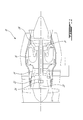
- Fig.1 illustrates a gas turbine engine 10 of a type preferably provided for use in subsonic flight, generally comprising in serial flow communication a fan 12 through which ambient air is propelled, a compressor section 14 for pressurizing the air, a combustor 16 in which the compressed air is mixed with fuel and ignited for generating an annular stream of hot combustion gases, and a turbine section 18 for extracting energy from the combustion gases.
- the fan 12 is a geared fan: the fan drive shaft 20 is driven by the low pressure shaft 22 through a gearbox 24, and the low pressure shaft 22 is driven by low pressure rotor(s) 26 of the turbine section 18.
- the fan drive shaft 20 may be directly driven by the low pressure shaft 22, for example by being integral therewith.
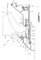
- An annular sleeve 30 has a "C" shape cross-section, defined by annular, substantially axially extending and concentric inner and outer members 34, 36.
- the inner member 34 is connected around the shaft 20 to rotate together therewith, for example through a spline connection 32.
- the connection 32 allows relative axial movement between the sleeve 30 and the shaft 20, the purpose of which will be further detailed below.
- the inner and outer members 34, 36 are radially spaced apart from one another and connected by a radially extending front end wall 38.
- the sleeve 30 thus defines an annular slot 40 opening into its rear end 42.
- the slot 40 is defined between first and second spaced apart annular surfaces 44, 46, the first surface 44 corresponding to the radially outer surface of the inner member 34 and the second surface 46 corresponding to the radially inner surface of the outer member 36.
- the annular inner surface 46 of the outer member 36 is frustoconical, and is angled to extend closer to the central axis C of the assembly near the front end wall 38 than away therefrom.
- the inner surface 46 of the outer member 36 is also continuous, i.e. it has a smooth regular surface free of slots, keys, splines or similar engagement members.
- the front end of the sleeve 30 includes an annular abutment portion 48.
- the abutment portion 48 is defined by an annular projection extending axially from the front end wall 38 and surrounding the shaft 20.
- the fan rotor 28 has an annular disc 50 having an enlarged outer perimeter portion 52 on which are supported a plurality of blades 54 extending radially outwardly therefrom.
- the disc 50 also has a central opening 56 defined therethrough, through which the shaft 20 extends, with the disc 50 being located rearwardly of the sleeve 30.
- the front end of the disc 50 has an annular recess 58 defined therein, separating the enlarged outer perimeter portion 52 from an annular protuberance 60 extending substantially axially around the central opening 56.
- the curved rear profile of the disc 50 defines an annular abutment portion 62 extending substantially axially around the central opening 56 opposite to the protuberance 60, and opposite to the abutment portion 48 of the sleeve 30.
- the protuberance 60 of the disc 50 is received in the slot 40 of the sleeve 30.
- the protuberance 60 defines a frustoconical outer surface 64 which is continuous, i.e. has a smooth regular surface free of slots, keys, splines or similar engagement members, and complementary to the inner surface 46 of the outer member 36 to define a torque transmitting engagement therewith.
- the outer member 36 of the sleeve 30 is received in the annular recess 58 of the disc 50 and sized such that the rear end 42 of the outer member 36 is axially spaced apart from the adjacent front wall 66 of the disc 50.
- the central opening 56 of the disc 50 defines an annular gap between the first surface 44 of the slot 40 and the protuberance 60, and between the shaft 20 and the abutment portion 62 of the disc 50.
- a locking member 70 is engaged to the shaft 20 and presses axially against the abutment portion 48 of the sleeve 30, while the abutment portion 62 of the disc 50 abuts an annular shoulder 72 having a fixed axial position relative to the shaft 20.
- the shoulder 72 is formed by the end of a cylindrical member 74 surrounding the shaft 20 and abutting the shaft bearing 76.
- the locking member 70 moves the sleeve 30 axially toward the disc 50; the abutment portion 62 in contact with the shoulder 72 prevents movement of the engaged disc 50 and sleeve 30 toward the shoulder 72.
- the pressure applied by the locking member 70 thus creates a clamping force which forces the insertion of the protuberance 60 to a predetermined position within the slot 40 and against the interference between the complementary frustoconical surfaces 46, 64.
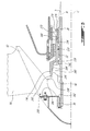
- the annular sleeve 130 has a "Z" shaped cross-section.
- the sleeve 130 thus includes annular, substantially axially extending inner and outer members 134, 136 which are radially and axially spaced apart from one another.
- the outer member 136 is located forwardly of the inner member 134, and the rear end of the outer member 136 and front end of the inner member 134 are interconnected by a radial wall 138 extending at least approximately along the radial direction.
- the inner member 134 is connected around the shaft 20 to rotate together therewith while allowing relative axial movement, for example through the spline connection 32, and an annular slot 140 is defined between the outer member 136 and the shaft 20.
- the annular radially inner surface 146 of the outer member 136 is frustoconical and is angled to extend closer to the central axis C of the assembly near the radial wall 138 than away therefrom.
- the inner surface 146 of the outer member 136 is also continuous, i.e. it has a smooth regular surface free of slots, keys, splines or similar engagement members.
- the rear end of the sleeve 130 includes an annular abutment portion 148, defined by the rear end of the inner member 134.
- the fan disc 150 is located forwardly of the sleeve 130.
- the rear end of the disc 150 has an annular recess 158 defined therein, separating the enlarged outer perimeter portion 52 from an annular protuberance 160 extending substantially axially around the central opening 56 of the disc 150.
- the curved front profile of the disc 150 defines an annular abutment portion 162 extending substantially axially around the central opening 56 opposite to the protuberance 160, and opposite to the abutment portion 148 of the sleeve 130.
- the protuberance 160 of the disc 150 is received inwardly of the outer member 136 of the sleeve 130.
- the protuberance 160 defines a frustoconical outer surface 164 which is continuous, i.e. has a smooth regular surface free of slots, keys, splines or similar engagement members, and complementary to the inner surface 146 of the outer member 136 of the sleeve 130 to define a torque transmitting engagement therewith.
- the outer member 136 of the sleeve 130 is received in the annular recess 158 of the disc 150 and sized such that the front end 142 of the outer member 136 is axially spaced apart from the adjacent rear wall 166 of the disc 150.
- the central opening 56 of the disc 150 defines an annular gap between the shaft 20 and the disc 150.
- the locking member 70 is engaged to the shaft 20 and presses axially against the abutment portion 162 of the disc 150, while the abutment portion 148 of the sleeve 130 abuts an annular shoulder 172 having a fixed axial position relative to the shaft 20.
- the shoulder 172 is formed by the inner race 174 of a shaft bearing in abutment with a shoulder 175 defined in the shaft 20.
- the locking member 70 moves the disc 150 axially toward the sleeve 130; the abutment portion 148 in contact with the shoulder 172 prevents movement of the engaged disc 150 and sleeve 130 toward the shoulder 172.
- the pressure applied by the locking member 70 thus creates a clamping force which forces the insertion of the protuberance 160 to a predetermined position inwardly of the sleeve outer member 136 and against the interference between the complementary frustoconical surfaces 146, 164.
- the locking member 70 is a retaining nut threadingly engaged to the shaft 20 and threaded to press against the abutment portion 48 of the sleeve 30 ( Fig. 2 ) or the abutment portion 162 of the disc 150 ( Fig. 3 ).
- Other types of locking members can alternately be used.
- the retaining nut 70 is engaged to the shaft 20 with a predetermined torque which produces a desired force against the corresponding abutment portion 48, 162 to force the protuberance 60, 160 to the predetermined position.
- This forced engagement of the protuberance 60, 160 with the sleeve outer member 36, 136 creates the torque-transmitting engagement of the frustoconical surfaces 46, 64, 146, 164.
- the predetermined torque is a function of the frustoconical angle definition of the joint and the transmitting torque requirement of the system.
- the selected angle of the joint also is such that the force required to split the connected frustoconical surfaces 46, 64, 146, 164 i.e. to produce a relative slipping movement therebetween, is within the structural requirements of the assembly as a whole.
- the angle ⁇ of the frustoconical surfaces 46, 64, 146, 164 is selected such as to be able to transmit the required torque of the fan rotor 28 at all engine conditions.
- the angle ⁇ is at least 3° and at most 10° from the axial direction A. In a particular embodiment, the angle ⁇ is about 7° from the axial direction A.
- the frustoconical surfaces 46, 64, 146, 164 are manufactured using a turning process.
- the engaged continuous frustoconical surfaces 46, 64, 146, 164 may be particularly beneficial when the fan disc 50, 150 is made of a material less rigid than that of the sleeve 30, 130, and in which case stress concentrations produced by a spline, bolted joint, curvic coupling or similar attachment may be unacceptable.
- the disc 50, 150 is made of aluminium and the sleeve 30, 130 is made of titanium or steel.
- the engaged continuous frustoconical surfaces 46, 64, 146, 164 may allow for stress concentrations at the connection to be reduced, and may increase the low cycle fatigue life of the assembly.
- the engaged continuous frustoconical surfaces 46, 64, 146, 164 may also be used between other rotors of the gas turbine engine 10 and their respective driving shaft, for example on small diameter rotors and/or rotors rotating at relatively slow speeds such as geared rotors, in the cold section of the engine 10.
- the engaged continuous frustoconical surfaces 46, 64, 146, 164 may be used to connect a booster rotor to its driving shaft.
Landscapes
- Engineering & Computer Science (AREA)
- Mechanical Engineering (AREA)
- General Engineering & Computer Science (AREA)
- Chemical & Material Sciences (AREA)
- Combustion & Propulsion (AREA)
- Structures Of Non-Positive Displacement Pumps (AREA)
- Turbine Rotor Nozzle Sealing (AREA)
Applications Claiming Priority (1)
| Application Number | Priority Date | Filing Date | Title |
|---|---|---|---|
| US13/614,584 US9353626B2 (en) | 2012-09-13 | 2012-09-13 | Rotor assembly |
Publications (3)
| Publication Number | Publication Date |
|---|---|
| EP2708698A2 true EP2708698A2 (de) | 2014-03-19 |
| EP2708698A3 EP2708698A3 (de) | 2017-04-12 |
| EP2708698B1 EP2708698B1 (de) | 2019-12-25 |
Family
ID=49161995
Family Applications (1)
| Application Number | Title | Priority Date | Filing Date |
|---|---|---|---|
| EP13183782.5A Active EP2708698B1 (de) | 2012-09-13 | 2013-09-10 | Geblaserotoranordnung |
Country Status (3)
| Country | Link |
|---|---|
| US (1) | US9353626B2 (de) |
| EP (1) | EP2708698B1 (de) |
| CA (1) | CA2826691C (de) |
Cited By (3)
| Publication number | Priority date | Publication date | Assignee | Title |
|---|---|---|---|---|
| FR3057907A1 (fr) * | 2016-10-24 | 2018-04-27 | Safran Aircraft Engines | Ensemble a effet anti-usure pour turboreacteur |
| FR3128248A1 (fr) * | 2021-10-14 | 2023-04-21 | Safran Aircraft Engines Mexico S.a. De C.v. | Assemblage d’une soufflante de turbomachine à aubes |
| FR3141489A1 (fr) * | 2022-11-02 | 2024-05-03 | Safran Aircraft Engines | Assemblage pour turbomachine comprenant un disque de soufflante et un arbre de compresseur |
Families Citing this family (3)
| Publication number | Priority date | Publication date | Assignee | Title |
|---|---|---|---|---|
| FR3066552B1 (fr) * | 2017-05-22 | 2021-11-19 | Safran Aircraft Engines | Assemblage sur un arbre de turbomachine d'un disque aubage monobloc et d'un rotor de compresseur basse pression a au moins deux etages d'aubes mobiles |
| US11365630B1 (en) * | 2020-12-28 | 2022-06-21 | Rolls-Royce North American Technologies Inc. | Fan rotor with tapered drive joint |
| FR3128249A1 (fr) * | 2021-10-14 | 2023-04-21 | Safran Aircraft Engines Mexico S.a. De C.v. | Assemblage d’une soufflante de turbomachine à aubes |
Family Cites Families (21)
| Publication number | Priority date | Publication date | Assignee | Title |
|---|---|---|---|---|
| AT112883B (de) * | 1927-06-20 | 1929-04-10 | Bbc Brown Boveri & Cie | Einrichtung zur Befestigung einer Scheibe auf der durch die Nabe hindurchgehenden Welle. |
| US2228770A (en) | 1938-08-19 | 1941-01-14 | Letourneau Inc | Shaft and hub mounting |
| US2932447A (en) | 1958-05-07 | 1960-04-12 | Russell E Phelon | Flywheel for use with an internal combustion engine |
| US3273920A (en) * | 1963-04-08 | 1966-09-20 | Borg Warner | Combination shaft and hub assembly for centrifugal compressor |
| US3307423A (en) | 1964-03-16 | 1967-03-07 | Dansi S P A Off | Fly-wheel magneto with hub incorporated therewith during casting |
| US3604819A (en) | 1969-10-14 | 1971-09-14 | United States Steel Corp | Impeller shaft assembly |
| US3601501A (en) * | 1970-02-26 | 1971-08-24 | John G Johnson | Gas compressor impeller and shaft assembly |
| US4292001A (en) * | 1978-09-19 | 1981-09-29 | Rolls-Royce Limited | Shaft coupling |
| US4304502A (en) * | 1979-11-15 | 1981-12-08 | Andrew Stratienko | Torque and thrust transmitting bushings |
| JPS58124002A (ja) * | 1982-01-20 | 1983-07-23 | Toyota Motor Corp | タ−ボチヤ−ジヤのインペラ組み付け方法 |
| GB8325602D0 (en) | 1983-09-23 | 1983-10-26 | British Petroleum Co | Energy storage flywheels |
| JPS62172823U (de) | 1986-04-23 | 1987-11-02 | ||
| JPH0672616B2 (ja) | 1987-04-21 | 1994-09-14 | 株式会社ゼクセル | 鋼シャフト複合アルミニウム合金ローター |
| DE4001659C2 (de) | 1989-08-24 | 1993-10-07 | Mannesmann Ag | Kraftschlüssige, kegelförmige Preßverbindung |
| US5245954A (en) | 1992-07-02 | 1993-09-21 | Outboard Marine Corporation | Axial fan flywheel |
| DE4445297C1 (de) * | 1994-12-19 | 1996-03-14 | Man B & W Diesel Ag | Laufrad für eine Strömungsmaschine |
| DE19517258A1 (de) | 1995-05-11 | 1996-11-14 | Alpha Getriebebau Gmbh | Wellen-Befestigung |
| CA2321641A1 (en) | 1998-02-27 | 1999-09-02 | Allison Engine Company, Inc. | Method and apparatus for mounting a bearing |
| EP1387102A1 (de) | 2002-07-31 | 2004-02-04 | Robert Bürgler | Aufpressbare Nabe und Nockenwelle |
| US7217226B2 (en) | 2003-02-04 | 2007-05-15 | Mcmillan Electric Company | Method and system for coupling a flywheel assembly onto a shaft of an electric motor using a self-holding taper |
| US7527479B2 (en) * | 2005-09-08 | 2009-05-05 | Hamilton Sundstrand Corporation | Mechanical coupling for a rotor shaft assembly of dissimilar materials |
-
2012
- 2012-09-13 US US13/614,584 patent/US9353626B2/en active Active
-
2013
- 2013-09-10 EP EP13183782.5A patent/EP2708698B1/de active Active
- 2013-09-10 CA CA2826691A patent/CA2826691C/en active Active
Non-Patent Citations (1)
| Title |
|---|
| None |
Cited By (3)
| Publication number | Priority date | Publication date | Assignee | Title |
|---|---|---|---|---|
| FR3057907A1 (fr) * | 2016-10-24 | 2018-04-27 | Safran Aircraft Engines | Ensemble a effet anti-usure pour turboreacteur |
| FR3128248A1 (fr) * | 2021-10-14 | 2023-04-21 | Safran Aircraft Engines Mexico S.a. De C.v. | Assemblage d’une soufflante de turbomachine à aubes |
| FR3141489A1 (fr) * | 2022-11-02 | 2024-05-03 | Safran Aircraft Engines | Assemblage pour turbomachine comprenant un disque de soufflante et un arbre de compresseur |
Also Published As
| Publication number | Publication date |
|---|---|
| US20140072444A1 (en) | 2014-03-13 |
| EP2708698B1 (de) | 2019-12-25 |
| EP2708698A3 (de) | 2017-04-12 |
| CA2826691C (en) | 2022-07-19 |
| US9353626B2 (en) | 2016-05-31 |
| CA2826691A1 (en) | 2014-03-13 |
Similar Documents
| Publication | Publication Date | Title |
|---|---|---|
| EP2708698B1 (de) | Geblaserotoranordnung | |
| EP2199573B1 (de) | Generatorkupplung zur Verwendung mit Gasturbinenmotor | |
| US8608436B2 (en) | Tapered collet connection of rotor components | |
| EP2365184A2 (de) | Gasturbinentriebwerk mit kraftschlüssiger Wellenverbindung für den Rotor des Hochdruck-Axialverdichters | |
| EP2668411B1 (de) | Drehmomentbegrenzungskupplung | |
| US8465373B2 (en) | Face coupling | |
| CA2975691C (en) | Spline alignment | |
| CN103154441A (zh) | 用于将推力反向器前框架连接至风扇罩的装置以及包含此装置的机舱 | |
| EP3751096B1 (de) | Turbinenanordnung | |
| US20170058675A1 (en) | Low diameter turbine rotor clamping arrangement | |
| US10001029B2 (en) | Bearing locking assemblies and methods of assembling the same | |
| EP4339094B1 (de) | Propellerwelle mit verstärktem vorderflansch | |
| EP2383433A1 (de) | Kompressorabschnitt mit Zuganker und freitragenden Leitschaufeln | |
| US8864406B2 (en) | Splined couplings | |
| US11149741B2 (en) | Variable pitch fan for a gas turbine engine | |
| EP3106612B1 (de) | Gasturbinenanordnung | |
| US11365630B1 (en) | Fan rotor with tapered drive joint | |
| EP3396144B1 (de) | Gasturbinenmotor mit getriebefananordnung | |
| EP4339093A1 (de) | Propellerwellenanordnung für ein flugzeugtriebwerk | |
| EP4343113A1 (de) | Befestigungssystem | |
| US20250092799A1 (en) | Shaft for a gas turbine engine |
Legal Events
| Date | Code | Title | Description |
|---|---|---|---|
| PUAI | Public reference made under article 153(3) epc to a published international application that has entered the european phase |
Free format text: ORIGINAL CODE: 0009012 |
|
| AK | Designated contracting states |
Kind code of ref document: A2 Designated state(s): AL AT BE BG CH CY CZ DE DK EE ES FI FR GB GR HR HU IE IS IT LI LT LU LV MC MK MT NL NO PL PT RO RS SE SI SK SM TR |
|
| AX | Request for extension of the european patent |
Extension state: BA ME |
|
| PUAL | Search report despatched |
Free format text: ORIGINAL CODE: 0009013 |
|
| AK | Designated contracting states |
Kind code of ref document: A3 Designated state(s): AL AT BE BG CH CY CZ DE DK EE ES FI FR GB GR HR HU IE IS IT LI LT LU LV MC MK MT NL NO PL PT RO RS SE SI SK SM TR |
|
| AX | Request for extension of the european patent |
Extension state: BA ME |
|
| RIC1 | Information provided on ipc code assigned before grant |
Ipc: F01D 5/02 20060101AFI20170309BHEP Ipc: F04D 29/26 20060101ALI20170309BHEP Ipc: F02K 3/06 20060101ALI20170309BHEP |
|
| STAA | Information on the status of an ep patent application or granted ep patent |
Free format text: STATUS: REQUEST FOR EXAMINATION WAS MADE |
|
| 17P | Request for examination filed |
Effective date: 20171012 |
|
| RBV | Designated contracting states (corrected) |
Designated state(s): AL AT BE BG CH CY CZ DE DK EE ES FI FR GB GR HR HU IE IS IT LI LT LU LV MC MK MT NL NO PL PT RO RS SE SI SK SM TR |
|
| GRAP | Despatch of communication of intention to grant a patent |
Free format text: ORIGINAL CODE: EPIDOSNIGR1 |
|
| STAA | Information on the status of an ep patent application or granted ep patent |
Free format text: STATUS: GRANT OF PATENT IS INTENDED |
|
| INTG | Intention to grant announced |
Effective date: 20190703 |
|
| GRAS | Grant fee paid |
Free format text: ORIGINAL CODE: EPIDOSNIGR3 |
|
| GRAA | (expected) grant |
Free format text: ORIGINAL CODE: 0009210 |
|
| STAA | Information on the status of an ep patent application or granted ep patent |
Free format text: STATUS: THE PATENT HAS BEEN GRANTED |
|
| AK | Designated contracting states |
Kind code of ref document: B1 Designated state(s): AL AT BE BG CH CY CZ DE DK EE ES FI FR GB GR HR HU IE IS IT LI LT LU LV MC MK MT NL NO PL PT RO RS SE SI SK SM TR |
|
| REG | Reference to a national code |
Ref country code: GB Ref legal event code: FG4D |
|
| REG | Reference to a national code |
Ref country code: CH Ref legal event code: EP |
|
| REG | Reference to a national code |
Ref country code: DE Ref legal event code: R096 Ref document number: 602013064288 Country of ref document: DE |
|
| REG | Reference to a national code |
Ref country code: AT Ref legal event code: REF Ref document number: 1217330 Country of ref document: AT Kind code of ref document: T Effective date: 20200115 |
|
| REG | Reference to a national code |
Ref country code: IE Ref legal event code: FG4D |
|
| REG | Reference to a national code |
Ref country code: NL Ref legal event code: MP Effective date: 20191225 |
|
| PG25 | Lapsed in a contracting state [announced via postgrant information from national office to epo] |
Ref country code: FI Free format text: LAPSE BECAUSE OF FAILURE TO SUBMIT A TRANSLATION OF THE DESCRIPTION OR TO PAY THE FEE WITHIN THE PRESCRIBED TIME-LIMIT Effective date: 20191225 Ref country code: BG Free format text: LAPSE BECAUSE OF FAILURE TO SUBMIT A TRANSLATION OF THE DESCRIPTION OR TO PAY THE FEE WITHIN THE PRESCRIBED TIME-LIMIT Effective date: 20200325 Ref country code: LV Free format text: LAPSE BECAUSE OF FAILURE TO SUBMIT A TRANSLATION OF THE DESCRIPTION OR TO PAY THE FEE WITHIN THE PRESCRIBED TIME-LIMIT Effective date: 20191225 Ref country code: SE Free format text: LAPSE BECAUSE OF FAILURE TO SUBMIT A TRANSLATION OF THE DESCRIPTION OR TO PAY THE FEE WITHIN THE PRESCRIBED TIME-LIMIT Effective date: 20191225 Ref country code: LT Free format text: LAPSE BECAUSE OF FAILURE TO SUBMIT A TRANSLATION OF THE DESCRIPTION OR TO PAY THE FEE WITHIN THE PRESCRIBED TIME-LIMIT Effective date: 20191225 Ref country code: NO Free format text: LAPSE BECAUSE OF FAILURE TO SUBMIT A TRANSLATION OF THE DESCRIPTION OR TO PAY THE FEE WITHIN THE PRESCRIBED TIME-LIMIT Effective date: 20200325 Ref country code: GR Free format text: LAPSE BECAUSE OF FAILURE TO SUBMIT A TRANSLATION OF THE DESCRIPTION OR TO PAY THE FEE WITHIN THE PRESCRIBED TIME-LIMIT Effective date: 20200326 |
|
| REG | Reference to a national code |
Ref country code: LT Ref legal event code: MG4D |
|
| PG25 | Lapsed in a contracting state [announced via postgrant information from national office to epo] |
Ref country code: HR Free format text: LAPSE BECAUSE OF FAILURE TO SUBMIT A TRANSLATION OF THE DESCRIPTION OR TO PAY THE FEE WITHIN THE PRESCRIBED TIME-LIMIT Effective date: 20191225 Ref country code: RS Free format text: LAPSE BECAUSE OF FAILURE TO SUBMIT A TRANSLATION OF THE DESCRIPTION OR TO PAY THE FEE WITHIN THE PRESCRIBED TIME-LIMIT Effective date: 20191225 |
|
| PG25 | Lapsed in a contracting state [announced via postgrant information from national office to epo] |
Ref country code: AL Free format text: LAPSE BECAUSE OF FAILURE TO SUBMIT A TRANSLATION OF THE DESCRIPTION OR TO PAY THE FEE WITHIN THE PRESCRIBED TIME-LIMIT Effective date: 20191225 |
|
| PG25 | Lapsed in a contracting state [announced via postgrant information from national office to epo] |
Ref country code: EE Free format text: LAPSE BECAUSE OF FAILURE TO SUBMIT A TRANSLATION OF THE DESCRIPTION OR TO PAY THE FEE WITHIN THE PRESCRIBED TIME-LIMIT Effective date: 20191225 Ref country code: RO Free format text: LAPSE BECAUSE OF FAILURE TO SUBMIT A TRANSLATION OF THE DESCRIPTION OR TO PAY THE FEE WITHIN THE PRESCRIBED TIME-LIMIT Effective date: 20191225 Ref country code: NL Free format text: LAPSE BECAUSE OF FAILURE TO SUBMIT A TRANSLATION OF THE DESCRIPTION OR TO PAY THE FEE WITHIN THE PRESCRIBED TIME-LIMIT Effective date: 20191225 Ref country code: PT Free format text: LAPSE BECAUSE OF FAILURE TO SUBMIT A TRANSLATION OF THE DESCRIPTION OR TO PAY THE FEE WITHIN THE PRESCRIBED TIME-LIMIT Effective date: 20200520 Ref country code: CZ Free format text: LAPSE BECAUSE OF FAILURE TO SUBMIT A TRANSLATION OF THE DESCRIPTION OR TO PAY THE FEE WITHIN THE PRESCRIBED TIME-LIMIT Effective date: 20191225 |
|
| PG25 | Lapsed in a contracting state [announced via postgrant information from national office to epo] |
Ref country code: SM Free format text: LAPSE BECAUSE OF FAILURE TO SUBMIT A TRANSLATION OF THE DESCRIPTION OR TO PAY THE FEE WITHIN THE PRESCRIBED TIME-LIMIT Effective date: 20191225 Ref country code: SK Free format text: LAPSE BECAUSE OF FAILURE TO SUBMIT A TRANSLATION OF THE DESCRIPTION OR TO PAY THE FEE WITHIN THE PRESCRIBED TIME-LIMIT Effective date: 20191225 Ref country code: IS Free format text: LAPSE BECAUSE OF FAILURE TO SUBMIT A TRANSLATION OF THE DESCRIPTION OR TO PAY THE FEE WITHIN THE PRESCRIBED TIME-LIMIT Effective date: 20200425 |
|
| REG | Reference to a national code |
Ref country code: DE Ref legal event code: R097 Ref document number: 602013064288 Country of ref document: DE |
|
| PG25 | Lapsed in a contracting state [announced via postgrant information from national office to epo] |
Ref country code: DK Free format text: LAPSE BECAUSE OF FAILURE TO SUBMIT A TRANSLATION OF THE DESCRIPTION OR TO PAY THE FEE WITHIN THE PRESCRIBED TIME-LIMIT Effective date: 20191225 Ref country code: ES Free format text: LAPSE BECAUSE OF FAILURE TO SUBMIT A TRANSLATION OF THE DESCRIPTION OR TO PAY THE FEE WITHIN THE PRESCRIBED TIME-LIMIT Effective date: 20191225 |
|
| PLBE | No opposition filed within time limit |
Free format text: ORIGINAL CODE: 0009261 |
|
| STAA | Information on the status of an ep patent application or granted ep patent |
Free format text: STATUS: NO OPPOSITION FILED WITHIN TIME LIMIT |
|
| REG | Reference to a national code |
Ref country code: AT Ref legal event code: MK05 Ref document number: 1217330 Country of ref document: AT Kind code of ref document: T Effective date: 20191225 |
|
| PG25 | Lapsed in a contracting state [announced via postgrant information from national office to epo] |
Ref country code: SI Free format text: LAPSE BECAUSE OF FAILURE TO SUBMIT A TRANSLATION OF THE DESCRIPTION OR TO PAY THE FEE WITHIN THE PRESCRIBED TIME-LIMIT Effective date: 20191225 |
|
| 26N | No opposition filed |
Effective date: 20200928 |
|
| PG25 | Lapsed in a contracting state [announced via postgrant information from national office to epo] |
Ref country code: AT Free format text: LAPSE BECAUSE OF FAILURE TO SUBMIT A TRANSLATION OF THE DESCRIPTION OR TO PAY THE FEE WITHIN THE PRESCRIBED TIME-LIMIT Effective date: 20191225 Ref country code: IT Free format text: LAPSE BECAUSE OF FAILURE TO SUBMIT A TRANSLATION OF THE DESCRIPTION OR TO PAY THE FEE WITHIN THE PRESCRIBED TIME-LIMIT Effective date: 20191225 |
|
| PG25 | Lapsed in a contracting state [announced via postgrant information from national office to epo] |
Ref country code: PL Free format text: LAPSE BECAUSE OF FAILURE TO SUBMIT A TRANSLATION OF THE DESCRIPTION OR TO PAY THE FEE WITHIN THE PRESCRIBED TIME-LIMIT Effective date: 20191225 |
|
| REG | Reference to a national code |
Ref country code: DE Ref legal event code: R119 Ref document number: 602013064288 Country of ref document: DE |
|
| PG25 | Lapsed in a contracting state [announced via postgrant information from national office to epo] |
Ref country code: MC Free format text: LAPSE BECAUSE OF FAILURE TO SUBMIT A TRANSLATION OF THE DESCRIPTION OR TO PAY THE FEE WITHIN THE PRESCRIBED TIME-LIMIT Effective date: 20191225 |
|
| REG | Reference to a national code |
Ref country code: CH Ref legal event code: PL |
|
| GBPC | Gb: european patent ceased through non-payment of renewal fee |
Effective date: 20200910 |
|
| REG | Reference to a national code |
Ref country code: BE Ref legal event code: MM Effective date: 20200930 |
|
| PG25 | Lapsed in a contracting state [announced via postgrant information from national office to epo] |
Ref country code: LU Free format text: LAPSE BECAUSE OF NON-PAYMENT OF DUE FEES Effective date: 20200910 |
|
| PG25 | Lapsed in a contracting state [announced via postgrant information from national office to epo] |
Ref country code: DE Free format text: LAPSE BECAUSE OF NON-PAYMENT OF DUE FEES Effective date: 20210401 Ref country code: FR Free format text: LAPSE BECAUSE OF NON-PAYMENT OF DUE FEES Effective date: 20200930 |
|
| PG25 | Lapsed in a contracting state [announced via postgrant information from national office to epo] |
Ref country code: BE Free format text: LAPSE BECAUSE OF NON-PAYMENT OF DUE FEES Effective date: 20200930 Ref country code: CH Free format text: LAPSE BECAUSE OF NON-PAYMENT OF DUE FEES Effective date: 20200930 Ref country code: LI Free format text: LAPSE BECAUSE OF NON-PAYMENT OF DUE FEES Effective date: 20200930 Ref country code: GB Free format text: LAPSE BECAUSE OF NON-PAYMENT OF DUE FEES Effective date: 20200910 Ref country code: IE Free format text: LAPSE BECAUSE OF NON-PAYMENT OF DUE FEES Effective date: 20200910 |
|
| PG25 | Lapsed in a contracting state [announced via postgrant information from national office to epo] |
Ref country code: TR Free format text: LAPSE BECAUSE OF FAILURE TO SUBMIT A TRANSLATION OF THE DESCRIPTION OR TO PAY THE FEE WITHIN THE PRESCRIBED TIME-LIMIT Effective date: 20191225 Ref country code: MT Free format text: LAPSE BECAUSE OF FAILURE TO SUBMIT A TRANSLATION OF THE DESCRIPTION OR TO PAY THE FEE WITHIN THE PRESCRIBED TIME-LIMIT Effective date: 20191225 Ref country code: CY Free format text: LAPSE BECAUSE OF FAILURE TO SUBMIT A TRANSLATION OF THE DESCRIPTION OR TO PAY THE FEE WITHIN THE PRESCRIBED TIME-LIMIT Effective date: 20191225 |
|
| PG25 | Lapsed in a contracting state [announced via postgrant information from national office to epo] |
Ref country code: MK Free format text: LAPSE BECAUSE OF FAILURE TO SUBMIT A TRANSLATION OF THE DESCRIPTION OR TO PAY THE FEE WITHIN THE PRESCRIBED TIME-LIMIT Effective date: 20191225 |