EP2708833B1 - Système de réfrigération en cascade - Google Patents
Système de réfrigération en cascade Download PDFInfo
- Publication number
- EP2708833B1 EP2708833B1 EP13181585.4A EP13181585A EP2708833B1 EP 2708833 B1 EP2708833 B1 EP 2708833B1 EP 13181585 A EP13181585 A EP 13181585A EP 2708833 B1 EP2708833 B1 EP 2708833B1
- Authority
- EP
- European Patent Office
- Prior art keywords
- temperature side
- high temperature
- cascade
- low temperature
- heat exchanger
- Prior art date
- Legal status (The legal status is an assumption and is not a legal conclusion. Google has not performed a legal analysis and makes no representation as to the accuracy of the status listed.)
- Active
Links
Images


Classifications
-
- F—MECHANICAL ENGINEERING; LIGHTING; HEATING; WEAPONS; BLASTING
- F25—REFRIGERATION OR COOLING; COMBINED HEATING AND REFRIGERATION SYSTEMS; HEAT PUMP SYSTEMS; MANUFACTURE OR STORAGE OF ICE; LIQUEFACTION SOLIDIFICATION OF GASES
- F25B—REFRIGERATION MACHINES, PLANTS OR SYSTEMS; COMBINED HEATING AND REFRIGERATION SYSTEMS; HEAT PUMP SYSTEMS
- F25B7/00—Compression machines, plants or systems, with cascade operation, i.e. with two or more circuits, the heat from the condenser of one circuit being absorbed by the evaporator of the next circuit
-
- F—MECHANICAL ENGINEERING; LIGHTING; HEATING; WEAPONS; BLASTING
- F25—REFRIGERATION OR COOLING; COMBINED HEATING AND REFRIGERATION SYSTEMS; HEAT PUMP SYSTEMS; MANUFACTURE OR STORAGE OF ICE; LIQUEFACTION SOLIDIFICATION OF GASES
- F25B—REFRIGERATION MACHINES, PLANTS OR SYSTEMS; COMBINED HEATING AND REFRIGERATION SYSTEMS; HEAT PUMP SYSTEMS
- F25B49/00—Arrangement or mounting of control or safety devices
- F25B49/02—Arrangement or mounting of control or safety devices for compression type machines, plants or systems
- F25B49/022—Compressor control arrangements
-
- F—MECHANICAL ENGINEERING; LIGHTING; HEATING; WEAPONS; BLASTING
- F25—REFRIGERATION OR COOLING; COMBINED HEATING AND REFRIGERATION SYSTEMS; HEAT PUMP SYSTEMS; MANUFACTURE OR STORAGE OF ICE; LIQUEFACTION SOLIDIFICATION OF GASES
- F25B—REFRIGERATION MACHINES, PLANTS OR SYSTEMS; COMBINED HEATING AND REFRIGERATION SYSTEMS; HEAT PUMP SYSTEMS
- F25B2339/00—Details of evaporators; Details of condensers
- F25B2339/04—Details of condensers
- F25B2339/047—Water-cooled condensers
-
- F—MECHANICAL ENGINEERING; LIGHTING; HEATING; WEAPONS; BLASTING
- F25—REFRIGERATION OR COOLING; COMBINED HEATING AND REFRIGERATION SYSTEMS; HEAT PUMP SYSTEMS; MANUFACTURE OR STORAGE OF ICE; LIQUEFACTION SOLIDIFICATION OF GASES
- F25B—REFRIGERATION MACHINES, PLANTS OR SYSTEMS; COMBINED HEATING AND REFRIGERATION SYSTEMS; HEAT PUMP SYSTEMS
- F25B2500/00—Problems to be solved
- F25B2500/26—Problems to be solved characterised by the startup of the refrigeration cycle
-
- F—MECHANICAL ENGINEERING; LIGHTING; HEATING; WEAPONS; BLASTING
- F25—REFRIGERATION OR COOLING; COMBINED HEATING AND REFRIGERATION SYSTEMS; HEAT PUMP SYSTEMS; MANUFACTURE OR STORAGE OF ICE; LIQUEFACTION SOLIDIFICATION OF GASES
- F25B—REFRIGERATION MACHINES, PLANTS OR SYSTEMS; COMBINED HEATING AND REFRIGERATION SYSTEMS; HEAT PUMP SYSTEMS
- F25B2600/00—Control issues
- F25B2600/02—Compressor control
- F25B2600/025—Compressor control by controlling speed
- F25B2600/0251—Compressor control by controlling speed with on-off operation
-
- F—MECHANICAL ENGINEERING; LIGHTING; HEATING; WEAPONS; BLASTING
- F25—REFRIGERATION OR COOLING; COMBINED HEATING AND REFRIGERATION SYSTEMS; HEAT PUMP SYSTEMS; MANUFACTURE OR STORAGE OF ICE; LIQUEFACTION SOLIDIFICATION OF GASES
- F25B—REFRIGERATION MACHINES, PLANTS OR SYSTEMS; COMBINED HEATING AND REFRIGERATION SYSTEMS; HEAT PUMP SYSTEMS
- F25B2700/00—Sensing or detecting of parameters; Sensors therefor
- F25B2700/21—Temperatures
- F25B2700/2103—Temperatures near a heat exchanger
Definitions
- the present invention relates to a cascade refrigerating system having a low temperature side refrigerating cycle and a high temperature side refrigerating cycle and a control method for such refrigerating cycle.
- Patent Literature 1 discloses a known cascade refrigerating system. More specifically, Patent Literature 1 discloses a starter device for a cascade refrigerating system provided with a low temperature side refrigerant line provided with low temperature side refrigerant piping having a low temperature side compressor, a cascade condenser, a low temperature side expansion valve and a low temperature side heat exchanger intervening thereon, and a high temperature side refrigerant line provided with high temperature side refrigerant piping having a high temperature side compressor, a condenser, a high temperature side expansion valve and a low temperature side heat exchanger, which exchanges heat with the cascade condenser, intervening thereon, wherein a controller which is equipped with a thermostat for detecting the temperature of the refrigerant flowing in a low pressure part of the high temperature side refrigerant piping, starts the high temperature side compressor at the time of starting operation, starts the low temperature side compressor when the detected temperature of the thermostat falls to or below a set temperature and, when the ref
- the high temperature side refrigerating cycle is started at the time of starting operation, and the low temperature side refrigerating cycle is started after confirming from the refrigerant temperature a pressure fall due to a fall of the low pressure of the high temperature side refrigerating cycle.
- Patent Literature 1 Japanese Unexamined Patent Application Publication No. Hei2(1990)-143056
- a cascade vapor compression refrigeration system having a high stage and a low stage is shown. Each stage has a compressor, evaporator, condenser and expansion device. The high-stage evaporator is in heat transfer relationship with the low-stage condenser. Control means are provided which are responsive to some characteristic related to outdoor temperature whereby high-stage compressor operation is permitted when the outdoor ambient is below a preset temperature and high-stage compressor operation is prevented when the outdoor ambient is above a preset temperature.
- a refrigeration device is constituted by heat-exchangeably connecting a vaporizer of a primary side refrigerant circuit and a condenser cascade of the secondary side refrigerant circuit, and uses carbon dioxide as the refrigerant in the secondary side refrigerant circuit. It is an object to enable lowering of design pressure in a refrigeration device using carbon dioxide as a refrigerant in a secondary side refrigerant circuit.
- the low pressure in the high temperature side refrigerating cycle may fall too low and, depending on the load level, the refrigerating cycle may prove poor in the rate of rise or inefficient.
- the present invention is intended to restrain a fall in space heating capacity due to a deterioration in the rate of rise by suppressing losses at the time of rise of the refrigerating cycle in a cascade refrigerating system.
- a cascade refrigerating system according to the invention has the features of claim 1.
- a control method for use in a cascade refrigerating system according to claim 1, has the features of claim 3.
- a low temperature side refrigerating cycle in which a low temperature side compressor, a cascade heat exchanger, a low temperature side expansion valve and a low temperature side heat exchanger (an evaporator) are connected by low temperature side refrigerant piping and a high temperature side refrigerating cycle in which a high temperature side compressor, a condenser for exchanging heat between high temperature side refrigerant and refrigerated medium, a high temperature side expansion valve and the cascade heat exchanger are connected by high temperature side refrigerant piping are thermally connected via the cascade heat exchanger, and/or the low temperature side compressor is started when the cascade refrigerating system is to be started, and subsequently the high temperature side compressor is started.
- a low temperature side refrigerating cycle in which a low temperature side compressor, a cascade heat exchanger, a low temperature side expansion valve and a low temperature side heat exchanger (an evaporator) are connected by low temperature side refrigerant piping and a high temperature side refrigerating cycle in which a high temperature side compressor, a condenser for exchanging heat between high temperature side refrigerant and refrigerated medium, a high temperature side expansion valve and the cascade heat exchanger are connected by high temperature side refrigerant piping are thermally connected via the cascade heat exchanger, the low temperature side compressor is started when the cascade refrigerating system is to be started, and subsequently the high temperature side compressor is started.
- this embodiment which is a cascade refrigerating system in which the low temperature side refrigerating cycle and the high temperature side refrigerating cycle are thermally connected via the cascade heat exchanger
- the high temperature side compressor is started after the low temperature side compressor is started and the temperature of the cascade heat exchanger is raised, with the result that the cascade cycle can be started in a state in which the temperature of the cascade heat exchanger is high, so that a stable cascade cyclic operation is possible without inviting a fall in the low pressure of the high temperature side refrigerating cycle, and accordingly it is possible to restrain a fall in space heating capacity due to a deterioration in the rate of rise of the cascade refrigerating system.
- Fig. 1 is a conf igurational diagram of the refrigerating cycle when the cascade refrigerating system of this embodiment is in cascade heating operation.
- the cascade refrigerating system is provided with a low temperature side refrigerating cycle 1 and a high temperature side refrigerating cycle 10.
- the low temperature side refrigerating cycle 1 is configured by connecting a low temperature side compressor 2, an expansion valve 3, a low temperature side heat exchanger 4, a heat exchanger (a condenser) 20 and a cascade heat exchanger 21 by low temperature side refrigerating piping.
- the high temperature side refrigerating cycle 10 is configured by connecting a high temperature side compressor 11, the heat exchanger 20, a high temperature side expansion valve 12 and the cascade heat exchanger 21 by high temperature side refrigerating piping. Refrigerated medium is caused to flow into the heat exchanger 20 by being circulated by a pump, and is heated by its heat exchange with refrigerant in the heat exchanger 20, and warm water thereby generated is supplied to where it is needed.
- Fig. 2 is a control flow chart of the cascade refrigerating system of this embodiment. With reference to Fig. 2 , a control flow to start a cascade cycle from a state in which the cascade cycle of the cascade refrigerating system is at halt in cascade heating operation to supply high temperature water will be described below.
- the refrigerant compressed by the low temperature side compressor 2 turns into high pressure gas and flows into the cascade heat exchanger 21, in which the high pressure gas refrigerant is condensed by exchanging heat with low pressure gas-liquid refrigerant of the high temperature side refrigerating cycle 10.
- the condensed refrigerant is evaporated in the low temperature side heat exchanger 4 by exchanging heat with air taken in by a fan to become gasified.
- This gas refrigerant is reduced in pressure by the expansion valve 3 to turn into gas-liquid flow refrigerant, sucked into the compressor 2 to be compressed into high pressure gas again.
- this cyclic process is repeated.
- the refrigerant compressed in the high temperature side compressor 11 turns into high pressure gas, which flows into the heat exchanger 20 and exchanges heat with the refrigerated medium 30 to become liquefied.
- the liquid refrigerant is expanded by the expansion valve 12 under reduced pressure to turn into gas-liquid flow refrigerant and flows into the cascade heat exchanger 21, where it exchanges heat with gas refrigerant of the low temperature side refrigerating cycle 1 to become gasified.
- This gas refrigerant is sucked into the compressor 11 to be compressed into high pressure gas again. In the high temperature side refrigerating cycle 10, this cyclic process is repeated.
- the cascade refrigerating system is started (S1). If the temperature of the cascade heat exchanger 21 is low even though the low temperature side refrigerating cycle 1 is started, the pressure in the low temperature side refrigerating cycle 1 will fall. If the high temperature side refrigerating cycle 10 is started in a fallen state of the capacity of the low temperature side refrigerating cycle 1, the pressure in the low temperature side refrigerating cycle 1 will further fall, and the low pressure in the high temperature side refrigerating cycle 10 will also fall. This would mean a loss in calorific value at the time of rise, resulting in a cycle poor in the rate of rise.
- the high temperature side refrigerating cycle 10 is started in a state in which the low temperature side refrigerating cycle 1 is already started and the temperature of the cascade heat exchanger 21 is raised, a stable refrigerating cycle will be achieved without allowing the pressure in the high temperature side refrigerating cycle 10 to fall. Therefore, in order to start the low temperature side refrigerating cycle 1 to accomplish operation to raise the temperature of the cascade heat exchanger 21, first the low temperature side compressor 2 is started (S2). And when the temperature of the cascade heat exchanger 21 rises to a prescribed level (C°C) (S3), the high temperature side compressor 11 is started (S4). After that, usual cascade heating operation is performed (S5). By the cycle starting so far described, stable cycling operation is made possible at an improved rate of rise in cascade heating operation.
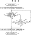
- Fig. 3 is another control flow chart of the cascade refrigerating system of this embodiment.
- the control charted in Fig. 2 can be replaced by that charted in Fig. 3 . More specifically, first the cascade refrigerating system is started (S1). Next, as in the case of Fig. 2 , the low temperature side compressor 2 is started (S2). And when the temperature of the cascade heat exchanger 21 has risen to the prescribed level (C°C) (S3-1), the high temperature side compressor 11 is started (S4).
- any abnormality is detected in the low temperature side refrigerating cycle 1 or in the high temperature side refrigerating cycle 10 during cascade heating operation and the low temperature side compressor 2 or the high temperature side compressor 11 is stopped, the low temperature side compressor 2 and the high temperature side compressor 11 is stopped, followed by retrial of starting.
- This retried starting can also be cascade heating operation similar to what was described with respect to the embodiment.
Landscapes
- Engineering & Computer Science (AREA)
- Physics & Mathematics (AREA)
- Mechanical Engineering (AREA)
- Thermal Sciences (AREA)
- General Engineering & Computer Science (AREA)
- Compression-Type Refrigeration Machines With Reversible Cycles (AREA)
- Air Conditioning Control Device (AREA)
- Devices That Are Associated With Refrigeration Equipment (AREA)
Claims (4)
- Système de réfrigération en cascade comprenant :un cycle de réfrigération côté basse température (1) dans lequel un compresseur côté basse température (2), un échangeur de chaleur en cascade (21), une vanne d'expansion côté basse température (3) et un échangeur de chaleur côté basse température (4) sont connectés par une tuyauterie pour réfrigérant côté basse température ;un cycle de réfrigération côté haute température (10) dans lequel un compresseur côté haute température (11), un échangeur de chaleur (20) pour échanger de la chaleur entre un réfrigérant côté haute température et un fluide réfrigéré (30), une vanne d'expansion côté haute température (12) et l'échangeur de chaleur en cascade (21) sont connectés par une tuyauterie pour réfrigérant côté haute température, dans lequel le cycle de réfrigération côté haute température (10) est connecté thermiquement au cycle de réfrigération côté basse température (1) via l'échangeur de chaleur en cascade (21) ; etun système de commande (40) ;caractérisé en ce quele système de commande (40) est configuré pour démarrer le compresseur côté basse température (2) quand le système de réfrigération en cascade est démarré, et- pour démarrer ensuite le compresseur côté haute température (11), à la condition que la température de l'échangeur de chaleur en cascade (21) ait atteint une température prescrite ; ou- pour démarrer le compresseur côté haute température (11) à la condition qu'une période temporelle prescrite se soit écoulée depuis le démarrage du compresseur côté basse température (2), même si la température de l'échangeur de chaleur en cascade (21) n'a pas atteint la température prescrite.
- Système de réfrigération en cascade selon la revendication 1, dans lequel le système de commande (40) est configuré pour arrêter le compresseur côté basse température (2) et le compresseur côté haute température (11) suivi d'un nouvel essai de démarrage, à la condition qu'une anomalie soit détectée pendant le fonctionnement dans le cycle de réfrigération côté basse température (1) ou dans le cycle de réfrigération côté haute température (10), et que le compresseur côté basse température (2) ou le compresseur côté haute température (11) soit arrêté.
- Procédé de commande pour utiliser un système de réfrigération en cascade qui inclut :un cycle de réfrigération côté basse température (1) dans lequel un compresseur côté basse température (2), un échangeur de chaleur en cascade (21), une vanne d'expansion côté basse température (3) et un échangeur de chaleur côté basse température (4) sont connectés par une tuyauterie pour réfrigérant côté basse température ; etun cycle de réfrigération côté haute température (10) dans lequel un compresseur côté haute température (11), un échangeur de chaleur (20) pour échanger de la chaleur entre un réfrigérant côté haute température et un fluide réfrigéré (30), une vanne d'expansion côté haute température (12) et l'échangeur de chaleur en cascade (21) sont connectés par une tuyauterie pour réfrigérant côté haute température, dans lequel le cycle de réfrigération côté haute température (10) est connecté thermiquement avec le cycle de réfrigération côté basse température (1) via l'échangeur de chaleur en cascade (21),caractérisé en ce que le procédé comprend les étapes consistant à :
démarrer le compresseur côté basse température (2) quand le système de réfrigération en cascade est démarré ; et- déterminer si la température de l'échangeur de chaleur en cascade (21) est plus élevée qu'une température prescrite ; et démarrer le compresseur côté haute température (11) si la température de l'échangeur de chaleur en cascade (21) est supérieure à la température prescrite ; ou- déterminer si une période temporelle prescrite s'est écoulée depuis le démarrage du compresseur côté basse température (2) ; et démarrer le compresseur côté haute température (11) si la période temporelle prescrite s'est écoulée depuis le démarrage du compresseur côté basse température (2), même si la température de l'échangeur de chaleur en cascade (21) n'a pas atteint la température prescrite. - Procédé de commande selon la revendication 3, comprenant en outre les étapes consistant à :
arrêter le compresseur côté basse température (2) et le compresseur côté haute température (11), effectuer à la suite un nouvel essai de démarrage, si une anomalie est détectée pendant le fonctionnement dans le cycle de réfrigération côté basse température (1) ou dans le cycle de réfrigération côté haute température (10) et que le compresseur côté basse température (2) ou le compresseur côté haute température (11)est arrêté.
Applications Claiming Priority (1)
| Application Number | Priority Date | Filing Date | Title |
|---|---|---|---|
| JP2012202191A JP2014055753A (ja) | 2012-09-14 | 2012-09-14 | 二元冷凍装置 |
Publications (2)
| Publication Number | Publication Date |
|---|---|
| EP2708833A1 EP2708833A1 (fr) | 2014-03-19 |
| EP2708833B1 true EP2708833B1 (fr) | 2020-03-25 |
Family
ID=49033908
Family Applications (1)
| Application Number | Title | Priority Date | Filing Date |
|---|---|---|---|
| EP13181585.4A Active EP2708833B1 (fr) | 2012-09-14 | 2013-08-23 | Système de réfrigération en cascade |
Country Status (4)
| Country | Link |
|---|---|
| EP (1) | EP2708833B1 (fr) |
| JP (1) | JP2014055753A (fr) |
| CN (1) | CN103673366B (fr) |
| ES (1) | ES2781483T3 (fr) |
Families Citing this family (6)
| Publication number | Priority date | Publication date | Assignee | Title |
|---|---|---|---|---|
| JP2015183929A (ja) * | 2014-03-24 | 2015-10-22 | サンデンホールディングス株式会社 | ヒートポンプ式暖房装置 |
| US20160265814A1 (en) * | 2015-03-11 | 2016-09-15 | Heatcraft Refrigeration Products Llc | Water Cooled Microchannel Condenser |
| CN104913435B (zh) * | 2015-05-12 | 2022-01-18 | 珠海格力电器股份有限公司 | 空调系统、空调器及其控制方法 |
| CN108266915A (zh) * | 2018-03-05 | 2018-07-10 | 天津商业大学 | 一种使用单一工质co2作制冷剂的复叠制冷系统 |
| CN109210817A (zh) * | 2018-10-22 | 2019-01-15 | 重庆优玛泰思特仪器有限公司 | 三级复叠制冷系统 |
| CN116951802A (zh) * | 2023-08-17 | 2023-10-27 | 无锡暖芯半导体科技有限公司 | 一种节能的宽温段双机复叠低温机组蒸发器模组装置 |
Family Cites Families (18)
| Publication number | Priority date | Publication date | Assignee | Title |
|---|---|---|---|---|
| JPS61101770A (ja) * | 1984-10-23 | 1986-05-20 | 三菱電機株式会社 | ヒ−トポンプ式冷暖房給湯機 |
| JPH07104060B2 (ja) * | 1988-11-24 | 1995-11-13 | ダイキン工業株式会社 | 二元冷凍装置の起動装置 |
| JPH03263556A (ja) * | 1990-03-12 | 1991-11-25 | Sanyo Electric Co Ltd | 多元冷凍装置 |
| JPH07104061B2 (ja) * | 1990-11-30 | 1995-11-13 | ダイキン工業株式会社 | 二元冷凍装置 |
| US5170639A (en) * | 1991-12-10 | 1992-12-15 | Chander Datta | Cascade refrigeration system |
| JPH08189713A (ja) * | 1995-01-13 | 1996-07-23 | Daikin Ind Ltd | 二元冷凍装置 |
| JP2000065431A (ja) * | 1998-08-24 | 2000-03-03 | Matsushita Electric Ind Co Ltd | 冷凍サイクル装置および冷凍サイクル装置用圧縮機 |
| JP3175706B2 (ja) * | 1998-09-30 | 2001-06-11 | ダイキン工業株式会社 | 二元冷凍装置 |
| JP2004190917A (ja) * | 2002-12-10 | 2004-07-08 | Sanyo Electric Co Ltd | 冷凍装置 |
| US6766652B2 (en) * | 2002-12-18 | 2004-07-27 | Gsle Development Corporation | Dual independent chamber ultra-low temperature freezer |
| JP2004286289A (ja) * | 2003-03-20 | 2004-10-14 | Sanyo Electric Co Ltd | 冷媒サイクル装置 |
| KR20050062077A (ko) * | 2003-12-19 | 2005-06-23 | 엘지전자 주식회사 | 이원 냉동시스템 |
| JP2006064199A (ja) * | 2004-08-24 | 2006-03-09 | Daikin Ind Ltd | 冷凍装置 |
| CN201021855Y (zh) * | 2006-12-20 | 2008-02-13 | 广东西屋康达空调有限公司 | 复叠耦合式高温热回收空调机组 |
| US20100147006A1 (en) * | 2007-06-04 | 2010-06-17 | Taras Michael F | Refrigerant system with cascaded circuits and performance enhancement features |
| EP2184563A4 (fr) * | 2008-02-04 | 2016-02-17 | Mitsubishi Electric Corp | Système complexe de climatisation et de chauffe-eau |
| JP5711448B2 (ja) * | 2009-02-24 | 2015-04-30 | ダイキン工業株式会社 | ヒートポンプシステム |
| CN102506502A (zh) * | 2011-10-19 | 2012-06-20 | 广东美的暖通设备限公司 | 蓄热式复叠循环热水机及其控制方法 |
-
2012
- 2012-09-14 JP JP2012202191A patent/JP2014055753A/ja active Pending
-
2013
- 2013-08-22 CN CN201310369623.1A patent/CN103673366B/zh active Active
- 2013-08-23 ES ES13181585T patent/ES2781483T3/es active Active
- 2013-08-23 EP EP13181585.4A patent/EP2708833B1/fr active Active
Non-Patent Citations (1)
| Title |
|---|
| None * |
Also Published As
| Publication number | Publication date |
|---|---|
| ES2781483T3 (es) | 2020-09-02 |
| CN103673366A (zh) | 2014-03-26 |
| CN103673366B (zh) | 2016-08-10 |
| JP2014055753A (ja) | 2014-03-27 |
| EP2708833A1 (fr) | 2014-03-19 |
Similar Documents
| Publication | Publication Date | Title |
|---|---|---|
| CN110914609B (zh) | 用于运输制冷单元的经济器的控制方法 | |
| CN107860103B (zh) | 多联机系统的控制方法、装置及具有其的系统 | |
| CN109373497B (zh) | 温度调节设备的冷媒量调节方法、装置、系统和空调 | |
| US8286438B2 (en) | System and method for controlling a refrigeration desuperheater | |
| JP5707621B2 (ja) | 恒温液循環装置及びその運転方法 | |
| EP2708833A1 (fr) | Système de réfrigération en cascade | |
| JP3915770B2 (ja) | ヒートポンプ給湯機 | |
| JP4337880B2 (ja) | ヒートポンプ式給湯器 | |
| JP6297072B2 (ja) | ヒートポンプ式給湯装置 | |
| JP6771988B2 (ja) | ヒートポンプ装置及びその制御方法 | |
| CN115468289B (zh) | 一种空调器及空调器的启动控制方法 | |
| JP2011257098A (ja) | ヒートポンプサイクル装置 | |
| JP6698312B2 (ja) | 制御装置、制御方法、及び熱源システム | |
| US11493226B2 (en) | Airconditioning apparatus | |
| JP5836844B2 (ja) | 冷凍装置 | |
| JP2005147437A (ja) | ヒートポンプ装置 | |
| JP6455752B2 (ja) | 冷凍システム | |
| JP2008249240A (ja) | コンデンシングユニット及びそれを備えた冷凍装置 | |
| JP6341481B2 (ja) | 冷凍システム | |
| CN114576794A (zh) | 空调器及其制热智能控制方法 | |
| JP2008170045A (ja) | 空調システムおよびその運転方法 | |
| WO2014185265A1 (fr) | Système de pompe à chaleur | |
| JP5772665B2 (ja) | ヒートポンプ式給湯装置 | |
| JPH11118283A (ja) | アンモニア吸収式冷凍機の制御装置 | |
| JPWO2019008660A1 (ja) | 空気調和システム |
Legal Events
| Date | Code | Title | Description |
|---|---|---|---|
| PUAI | Public reference made under article 153(3) epc to a published international application that has entered the european phase |
Free format text: ORIGINAL CODE: 0009012 |
|
| 17P | Request for examination filed |
Effective date: 20131004 |
|
| AK | Designated contracting states |
Kind code of ref document: A1 Designated state(s): AL AT BE BG CH CY CZ DE DK EE ES FI FR GB GR HR HU IE IS IT LI LT LU LV MC MK MT NL NO PL PT RO RS SE SI SK SM TR |
|
| AX | Request for extension of the european patent |
Extension state: BA ME |
|
| RAP1 | Party data changed (applicant data changed or rights of an application transferred) |
Owner name: JOHNSON CONTROLS-HITACHI AIR CONDITIONING TECHNOLO |
|
| STAA | Information on the status of an ep patent application or granted ep patent |
Free format text: STATUS: EXAMINATION IS IN PROGRESS |
|
| 17Q | First examination report despatched |
Effective date: 20170818 |
|
| RAP1 | Party data changed (applicant data changed or rights of an application transferred) |
Owner name: HITACHI-JOHNSON CONTROLS AIR CONDITIONING, INC. |
|
| GRAP | Despatch of communication of intention to grant a patent |
Free format text: ORIGINAL CODE: EPIDOSNIGR1 |
|
| STAA | Information on the status of an ep patent application or granted ep patent |
Free format text: STATUS: GRANT OF PATENT IS INTENDED |
|
| INTG | Intention to grant announced |
Effective date: 20191004 |
|
| GRAS | Grant fee paid |
Free format text: ORIGINAL CODE: EPIDOSNIGR3 |
|
| GRAA | (expected) grant |
Free format text: ORIGINAL CODE: 0009210 |
|
| STAA | Information on the status of an ep patent application or granted ep patent |
Free format text: STATUS: THE PATENT HAS BEEN GRANTED |
|
| AK | Designated contracting states |
Kind code of ref document: B1 Designated state(s): AL AT BE BG CH CY CZ DE DK EE ES FI FR GB GR HR HU IE IS IT LI LT LU LV MC MK MT NL NO PL PT RO RS SE SI SK SM TR |
|
| REG | Reference to a national code |
Ref country code: GB Ref legal event code: FG4D |
|
| REG | Reference to a national code |
Ref country code: AT Ref legal event code: REF Ref document number: 1249012 Country of ref document: AT Kind code of ref document: T Effective date: 20200415 Ref country code: IE Ref legal event code: FG4D |
|
| REG | Reference to a national code |
Ref country code: DE Ref legal event code: R096 Ref document number: 602013067106 Country of ref document: DE |
|
| PG25 | Lapsed in a contracting state [announced via postgrant information from national office to epo] |
Ref country code: RS Free format text: LAPSE BECAUSE OF FAILURE TO SUBMIT A TRANSLATION OF THE DESCRIPTION OR TO PAY THE FEE WITHIN THE PRESCRIBED TIME-LIMIT Effective date: 20200325 Ref country code: NO Free format text: LAPSE BECAUSE OF FAILURE TO SUBMIT A TRANSLATION OF THE DESCRIPTION OR TO PAY THE FEE WITHIN THE PRESCRIBED TIME-LIMIT Effective date: 20200625 Ref country code: FI Free format text: LAPSE BECAUSE OF FAILURE TO SUBMIT A TRANSLATION OF THE DESCRIPTION OR TO PAY THE FEE WITHIN THE PRESCRIBED TIME-LIMIT Effective date: 20200325 |
|
| PG25 | Lapsed in a contracting state [announced via postgrant information from national office to epo] |
Ref country code: LV Free format text: LAPSE BECAUSE OF FAILURE TO SUBMIT A TRANSLATION OF THE DESCRIPTION OR TO PAY THE FEE WITHIN THE PRESCRIBED TIME-LIMIT Effective date: 20200325 Ref country code: SE Free format text: LAPSE BECAUSE OF FAILURE TO SUBMIT A TRANSLATION OF THE DESCRIPTION OR TO PAY THE FEE WITHIN THE PRESCRIBED TIME-LIMIT Effective date: 20200325 Ref country code: HR Free format text: LAPSE BECAUSE OF FAILURE TO SUBMIT A TRANSLATION OF THE DESCRIPTION OR TO PAY THE FEE WITHIN THE PRESCRIBED TIME-LIMIT Effective date: 20200325 Ref country code: GR Free format text: LAPSE BECAUSE OF FAILURE TO SUBMIT A TRANSLATION OF THE DESCRIPTION OR TO PAY THE FEE WITHIN THE PRESCRIBED TIME-LIMIT Effective date: 20200626 Ref country code: BG Free format text: LAPSE BECAUSE OF FAILURE TO SUBMIT A TRANSLATION OF THE DESCRIPTION OR TO PAY THE FEE WITHIN THE PRESCRIBED TIME-LIMIT Effective date: 20200625 |
|
| REG | Reference to a national code |
Ref country code: ES Ref legal event code: FG2A Ref document number: 2781483 Country of ref document: ES Kind code of ref document: T3 Effective date: 20200902 Ref country code: NL Ref legal event code: MP Effective date: 20200325 |
|
| REG | Reference to a national code |
Ref country code: LT Ref legal event code: MG4D |
|
| PG25 | Lapsed in a contracting state [announced via postgrant information from national office to epo] |
Ref country code: NL Free format text: LAPSE BECAUSE OF FAILURE TO SUBMIT A TRANSLATION OF THE DESCRIPTION OR TO PAY THE FEE WITHIN THE PRESCRIBED TIME-LIMIT Effective date: 20200325 |
|
| PG25 | Lapsed in a contracting state [announced via postgrant information from national office to epo] |
Ref country code: SK Free format text: LAPSE BECAUSE OF FAILURE TO SUBMIT A TRANSLATION OF THE DESCRIPTION OR TO PAY THE FEE WITHIN THE PRESCRIBED TIME-LIMIT Effective date: 20200325 Ref country code: RO Free format text: LAPSE BECAUSE OF FAILURE TO SUBMIT A TRANSLATION OF THE DESCRIPTION OR TO PAY THE FEE WITHIN THE PRESCRIBED TIME-LIMIT Effective date: 20200325 Ref country code: IS Free format text: LAPSE BECAUSE OF FAILURE TO SUBMIT A TRANSLATION OF THE DESCRIPTION OR TO PAY THE FEE WITHIN THE PRESCRIBED TIME-LIMIT Effective date: 20200725 Ref country code: LT Free format text: LAPSE BECAUSE OF FAILURE TO SUBMIT A TRANSLATION OF THE DESCRIPTION OR TO PAY THE FEE WITHIN THE PRESCRIBED TIME-LIMIT Effective date: 20200325 Ref country code: CZ Free format text: LAPSE BECAUSE OF FAILURE TO SUBMIT A TRANSLATION OF THE DESCRIPTION OR TO PAY THE FEE WITHIN THE PRESCRIBED TIME-LIMIT Effective date: 20200325 Ref country code: PT Free format text: LAPSE BECAUSE OF FAILURE TO SUBMIT A TRANSLATION OF THE DESCRIPTION OR TO PAY THE FEE WITHIN THE PRESCRIBED TIME-LIMIT Effective date: 20200818 Ref country code: EE Free format text: LAPSE BECAUSE OF FAILURE TO SUBMIT A TRANSLATION OF THE DESCRIPTION OR TO PAY THE FEE WITHIN THE PRESCRIBED TIME-LIMIT Effective date: 20200325 Ref country code: SM Free format text: LAPSE BECAUSE OF FAILURE TO SUBMIT A TRANSLATION OF THE DESCRIPTION OR TO PAY THE FEE WITHIN THE PRESCRIBED TIME-LIMIT Effective date: 20200325 |
|
| REG | Reference to a national code |
Ref country code: AT Ref legal event code: MK05 Ref document number: 1249012 Country of ref document: AT Kind code of ref document: T Effective date: 20200325 |
|
| REG | Reference to a national code |
Ref country code: DE Ref legal event code: R097 Ref document number: 602013067106 Country of ref document: DE |
|
| PG25 | Lapsed in a contracting state [announced via postgrant information from national office to epo] |
Ref country code: DK Free format text: LAPSE BECAUSE OF FAILURE TO SUBMIT A TRANSLATION OF THE DESCRIPTION OR TO PAY THE FEE WITHIN THE PRESCRIBED TIME-LIMIT Effective date: 20200325 Ref country code: AT Free format text: LAPSE BECAUSE OF FAILURE TO SUBMIT A TRANSLATION OF THE DESCRIPTION OR TO PAY THE FEE WITHIN THE PRESCRIBED TIME-LIMIT Effective date: 20200325 Ref country code: IT Free format text: LAPSE BECAUSE OF FAILURE TO SUBMIT A TRANSLATION OF THE DESCRIPTION OR TO PAY THE FEE WITHIN THE PRESCRIBED TIME-LIMIT Effective date: 20200325 |
|
| PLBE | No opposition filed within time limit |
Free format text: ORIGINAL CODE: 0009261 |
|
| STAA | Information on the status of an ep patent application or granted ep patent |
Free format text: STATUS: NO OPPOSITION FILED WITHIN TIME LIMIT |
|
| PG25 | Lapsed in a contracting state [announced via postgrant information from national office to epo] |
Ref country code: PL Free format text: LAPSE BECAUSE OF FAILURE TO SUBMIT A TRANSLATION OF THE DESCRIPTION OR TO PAY THE FEE WITHIN THE PRESCRIBED TIME-LIMIT Effective date: 20200325 |
|
| REG | Reference to a national code |
Ref country code: DE Ref legal event code: R119 Ref document number: 602013067106 Country of ref document: DE |
|
| 26N | No opposition filed |
Effective date: 20210112 |
|
| PG25 | Lapsed in a contracting state [announced via postgrant information from national office to epo] |
Ref country code: MC Free format text: LAPSE BECAUSE OF FAILURE TO SUBMIT A TRANSLATION OF THE DESCRIPTION OR TO PAY THE FEE WITHIN THE PRESCRIBED TIME-LIMIT Effective date: 20200325 |
|
| REG | Reference to a national code |
Ref country code: CH Ref legal event code: PL |
|
| GBPC | Gb: european patent ceased through non-payment of renewal fee |
Effective date: 20200823 |
|
| PG25 | Lapsed in a contracting state [announced via postgrant information from national office to epo] |
Ref country code: LU Free format text: LAPSE BECAUSE OF NON-PAYMENT OF DUE FEES Effective date: 20200823 Ref country code: CH Free format text: LAPSE BECAUSE OF NON-PAYMENT OF DUE FEES Effective date: 20200831 Ref country code: LI Free format text: LAPSE BECAUSE OF NON-PAYMENT OF DUE FEES Effective date: 20200831 |
|
| REG | Reference to a national code |
Ref country code: BE Ref legal event code: MM Effective date: 20200831 |
|
| PG25 | Lapsed in a contracting state [announced via postgrant information from national office to epo] |
Ref country code: SI Free format text: LAPSE BECAUSE OF FAILURE TO SUBMIT A TRANSLATION OF THE DESCRIPTION OR TO PAY THE FEE WITHIN THE PRESCRIBED TIME-LIMIT Effective date: 20200325 |
|
| PG25 | Lapsed in a contracting state [announced via postgrant information from national office to epo] |
Ref country code: DE Free format text: LAPSE BECAUSE OF NON-PAYMENT OF DUE FEES Effective date: 20210302 |
|
| PG25 | Lapsed in a contracting state [announced via postgrant information from national office to epo] |
Ref country code: BE Free format text: LAPSE BECAUSE OF NON-PAYMENT OF DUE FEES Effective date: 20200831 Ref country code: IE Free format text: LAPSE BECAUSE OF NON-PAYMENT OF DUE FEES Effective date: 20200823 Ref country code: GB Free format text: LAPSE BECAUSE OF NON-PAYMENT OF DUE FEES Effective date: 20200823 |
|
| PG25 | Lapsed in a contracting state [announced via postgrant information from national office to epo] |
Ref country code: TR Free format text: LAPSE BECAUSE OF FAILURE TO SUBMIT A TRANSLATION OF THE DESCRIPTION OR TO PAY THE FEE WITHIN THE PRESCRIBED TIME-LIMIT Effective date: 20200325 Ref country code: MT Free format text: LAPSE BECAUSE OF FAILURE TO SUBMIT A TRANSLATION OF THE DESCRIPTION OR TO PAY THE FEE WITHIN THE PRESCRIBED TIME-LIMIT Effective date: 20200325 Ref country code: CY Free format text: LAPSE BECAUSE OF FAILURE TO SUBMIT A TRANSLATION OF THE DESCRIPTION OR TO PAY THE FEE WITHIN THE PRESCRIBED TIME-LIMIT Effective date: 20200325 |
|
| PG25 | Lapsed in a contracting state [announced via postgrant information from national office to epo] |
Ref country code: MK Free format text: LAPSE BECAUSE OF FAILURE TO SUBMIT A TRANSLATION OF THE DESCRIPTION OR TO PAY THE FEE WITHIN THE PRESCRIBED TIME-LIMIT Effective date: 20200325 Ref country code: AL Free format text: LAPSE BECAUSE OF FAILURE TO SUBMIT A TRANSLATION OF THE DESCRIPTION OR TO PAY THE FEE WITHIN THE PRESCRIBED TIME-LIMIT Effective date: 20200325 |
|
| PGFP | Annual fee paid to national office [announced via postgrant information from national office to epo] |
Ref country code: ES Payment date: 20250901 Year of fee payment: 13 |
|
| PGFP | Annual fee paid to national office [announced via postgrant information from national office to epo] |
Ref country code: FR Payment date: 20250725 Year of fee payment: 13 |