EP2708966A2 - Datenerfassungssystem für Funkenerosionsmaschinen - Google Patents
Datenerfassungssystem für Funkenerosionsmaschinen Download PDFInfo
- Publication number
- EP2708966A2 EP2708966A2 EP13182506.9A EP13182506A EP2708966A2 EP 2708966 A2 EP2708966 A2 EP 2708966A2 EP 13182506 A EP13182506 A EP 13182506A EP 2708966 A2 EP2708966 A2 EP 2708966A2
- Authority
- EP
- European Patent Office
- Prior art keywords
- physical quantity
- electric discharge
- machining
- discharge machine
- stored
- Prior art date
- Legal status (The legal status is an assumption and is not a legal conclusion. Google has not performed a legal analysis and makes no representation as to the accuracy of the status listed.)
- Granted
Links
Images

Classifications
-
- B—PERFORMING OPERATIONS; TRANSPORTING
- B23—MACHINE TOOLS; METAL-WORKING NOT OTHERWISE PROVIDED FOR
- B23H—WORKING OF METAL BY THE ACTION OF A HIGH CONCENTRATION OF ELECTRIC CURRENT ON A WORKPIECE USING AN ELECTRODE WHICH TAKES THE PLACE OF A TOOL; SUCH WORKING COMBINED WITH OTHER FORMS OF WORKING OF METAL
- B23H1/00—Electrical discharge machining, i.e. removing metal with a series of rapidly recurring electrical discharges between an electrode and a workpiece in the presence of a fluid dielectric
- B23H1/02—Electric circuits specially adapted therefor, e.g. power supply, control, preventing short circuits or other abnormal discharges
-
- G—PHYSICS
- G05—CONTROLLING; REGULATING
- G05B—CONTROL OR REGULATING SYSTEMS IN GENERAL; FUNCTIONAL ELEMENTS OF SUCH SYSTEMS; MONITORING OR TESTING ARRANGEMENTS FOR SUCH SYSTEMS OR ELEMENTS
- G05B19/00—Program-control systems
- G05B19/02—Program-control systems electric
- G05B19/18—Numerical control [NC], i.e. automatically operating machines, in particular machine tools, e.g. in a manufacturing environment, so as to execute positioning, movement or co-ordinated operations by means of program data in numerical form
- G05B19/406—Numerical control [NC], i.e. automatically operating machines, in particular machine tools, e.g. in a manufacturing environment, so as to execute positioning, movement or co-ordinated operations by means of program data in numerical form characterised by monitoring or safety
-
- G—PHYSICS
- G05—CONTROLLING; REGULATING
- G05B—CONTROL OR REGULATING SYSTEMS IN GENERAL; FUNCTIONAL ELEMENTS OF SUCH SYSTEMS; MONITORING OR TESTING ARRANGEMENTS FOR SUCH SYSTEMS OR ELEMENTS
- G05B2219/00—Program-control systems
- G05B2219/30—Nc systems
- G05B2219/35—Nc in input of data, input till input file format
- G05B2219/35529—Monitoring current machining, store information in database as a new working case
-
- G—PHYSICS
- G05—CONTROLLING; REGULATING
- G05B—CONTROL OR REGULATING SYSTEMS IN GENERAL; FUNCTIONAL ELEMENTS OF SUCH SYSTEMS; MONITORING OR TESTING ARRANGEMENTS FOR SUCH SYSTEMS OR ELEMENTS
- G05B2219/00—Program-control systems
- G05B2219/30—Nc systems
- G05B2219/37—Measurements
- G05B2219/37533—Real time processing of data acquisition, monitoring
-
- G—PHYSICS
- G05—CONTROLLING; REGULATING
- G05B—CONTROL OR REGULATING SYSTEMS IN GENERAL; FUNCTIONAL ELEMENTS OF SUCH SYSTEMS; MONITORING OR TESTING ARRANGEMENTS FOR SUCH SYSTEMS OR ELEMENTS
- G05B2219/00—Program-control systems
- G05B2219/30—Nc systems
- G05B2219/45—Nc applications
- G05B2219/45221—Edm, electrical discharge machining, electroerosion, ecm, chemical
Definitions
- the present invention relates to a data collection system for electric discharge machines in which a computer is connected with electric discharge machines over a network.
- a known technique for assessing the quality of a machined product manufactured by machining with an electric discharge machine is to measure and assess the surface roughness or dimensional accuracy of the machined product after machining.
- general assessing method of the quality of a machined product is to obtain monitoring information, such as machining voltage, machining current and machining speed which are used for keeping track of machining conditions during machining, and to asses the obtained monitoring information by determining the monitoring information falls within a prescribed range or not.
- monitoring information is stored in a storage device in a numerical controller mounted on the electric discharge machine or transferred to a computer over a network when the electric discharge machine is connected to a network.
- JP4137384B2 discloses a technique for collecting data on machining speed, machining voltage, machining current, on-time and off-time of voltage applied to electrodes, total number of discharges, the number of abnormal discharges, abnormal discharge rate and discharge frequency during machining with an electric discharge machine, and storing the collected data in a numerical controller mounted on the electric discharge machine.
- Such a numerical controller mounted on an electric discharge machine typically has a smaller data storage capacity than a personal computer or a server. This makes it difficult to store multiple kinds of monitoring information over all routes of electric discharge machining that takes a long machining time in terms of storage capacity. Also, mounting a large-capacity storage device on an electric discharge machine for storing various kinds of monitoring information increases costs of the electric discharge machine.
- Another known technique is to continuously transfer various kinds of monitoring information to a network-connected computer and store the information in a storage device in the computer, instead of storing them in the numerical controller mounted on the electric discharge machine. While this scheme avoids the problem of increase in costs of the electric discharge machine caused by mounting a large-capacity storage on the electric discharge machine as in the case of the above-mentioned patent document, constant transfer of data over a network can increase communication load on the network or result in monitoring information not being stored in the computer in the event of a failure on the network.
- JP4047544B2 discloses a system for collecting monitoring information such as variations in machining voltage and/or machining speed during machining via a network connection between a computer and an electric discharge machine.
- the system constituted by a computer and an electric discharge machine, is able to store monitoring information such as machining speed, machining voltage, and machining current during a machining process in the numerical controller in the electric discharge machine at predetermined time intervals and subsequently transmit the information to an external computer or the like as needed.
- This scheme has the disadvantage of data volume becoming large because it stores monitoring information at predetermined time intervals.
- the present invention addresses the above problems of the prior art technique with the object of providing a data collection system for electric discharge machines that is capable of collecting and storing various kinds of monitoring information during machining without adding a large-capacity storage device to a numerical controller mounted on the electric discharge machine.
- a computer is connected with electric discharge machines over a data transmission path, information on machining conditions of an electric discharge machine is stored in a storage unit of the electric discharge machine, and information sent from the electric discharge machine after completion of machining is collected by the computer.
- the electric discharge machine includes: a detection unit that detects a physical quantity relating to machining conditions during machining either at predetermined intervals or each time a moving part of the electric discharge machine has traveled a predetermined distance; a determination unit that determines whether the physical quantity detected by the detection unit exceeds a predetermined threshold or not; a storage unit that stores the physical quantity or information indicating the fact that the physical quantity exceeds the threshold when the determination unit determines that the detected physical quantity exceeds the predefined threshold; and a transmission unit that sends the physical quantity or the information indicating the fact that the physical quantity exceeds the threshold, stored in the storage unit, after the machining by the electric discharge machine.
- the computer includes: a reception unit that receives the physical quantity or the information indicating the fact that the physical quantity exceeds the threshold sent from the transmission unit after the machining by the electric discharge machine; and a storage unit that stores the physical quantity or the information indicating the fact that the physical quantity exceeds the threshold, received by the reception unit.
- electric discharge machines do not store all physical quantities that relate to machining conditions during machining but store them only when any physical quantity goes beyond a predetermined range. This minimizes monitoring information to be stored in the storage units of electric discharge machines and enables storage of necessary monitoring information even for electric discharge machining that involves a long machining time.
- physical quantities stored in the storage units of electric discharge machines are sent to the computer after completion of machining instead of being transferred over the network at all times, no problem would occur in information transmission if communication load on the network becomes high or a temporary trouble occurs on the network.
- cross a threshold used herein is intended to mean a transition from a range defined as “non-defective products” to another range defined as “defective products” in case where a range representing "non-defective products” and a range representing “defective products” are demarcated by a threshold, and is not necessarily used only to mean a transition from the smaller-valued range to the larger-valued range across the threshold.
- the the physical quantity may include one of: a machining voltage, a machining current, a machining speed, a temperature of a place where the electric discharge machine is installed, and a water temperature in a machining tank.
- the threshold may be a range defined by an upper limit and a lower limit of the physical quantity, and a plurality of such ranges are set for the physical quantity to be determined by the determination unit.
- the electric discharge machine may further include a setting unit that sets one or more items of physical quantities to be stored, from among the physical quantity to be determined by the determination unit and other physical quantities relating to the machining conditions, according to the respective ranges.
- the determination unit determines one of the set ranges within which the detected physical quantity falls.
- the storage unit stores the item of physical quantity, set by the setting unit according to the respective ranges, based on the determination result of the determination unit.
- physical quantities to be stored in the storage device of an electric discharge machine are minimized by varying the kinds of physical quantity to be stored in the storage device of the electric discharge machine in accordance with which range a physical quantity is determined to fall within.
- various kinds of monitoring information can be stored for a long machining time even in a numerical controller not having a large-capacity storage device.
- the threshold may be a range defined by an upper limit and a lower limit of the physical quantity, and a plurality of such ranges are set for the physical quantity to be determined by the determination unit.
- the electric discharge machine may further include a setting unit that selects, for each of the set ranges, one of: a storage mode that stores the physical quantity in a form of a measured value and another storage mode that stores the physical quantity in the form of a flag indicating whether the physical quantity falls within or outside the range.
- the determination unit determines one of the set ranges within which the detected physical quantity falls.
- the storage unit stores the physical quantity in the storage mode selected by the setting unit, based on the determination result of the determination unit.
- a physical quantity is stored in the storage device of an electric discharge machine in different forms, i.e., either as a flag or a measured value, depending on which range the physical quantity is determined to fall within, thereby minimizing physical quantities to be stored in the storage device.
- various kinds of monitoring information can be stored for a long machining time even in a numerical controller not having a large-capacity storage device.
- the physical quantity or the information indicating that the physical quantity exceeds the threshold stored in the storage unit of the electric discharge machine, exceeds a predetermined size
- the physical quantity or the information indicating that the physical quantity exceeds the threshold may be sent from the electric discharge machine to the computer, and the machining by the electric discharge machine is stopped.
- the physical quantity or data when the physical quantity or data exceeds a predetermined size, the physical quantity or data is sent from the electric discharge machine to the computer and operation of the electric discharge machine is stopped, thereby preventing an overflow of monitoring information that should be stored and a resulting failure to store them. It also can prevent machining from continuing with the physical quantity or data exceeding a predetermined size so that the product in process is not judged as defective and does not result in waste machining if the machining is continued in such a condition. Additionally, since the physical quantity or data in the electric discharge machine is sent to the computer upon exceeding the predetermined size, the physical quantity or data sent to the computer may be analyzed to determine the cause of the defectiveness and the like.
- the present invention by minimizing the amount of monitoring information temporarily stored in a numerical controller mounted on an electric discharge machine, various kinds of monitoring information can be stored without being affected by a network environment even if the numerical controller does not have a large-capacity storage device. Further, transfer of such monitoring information temporarily stored in the numerical controller to a computer connected over a network enables storage of a large volume of monitoring information.
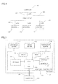
- FIG. 1 a data collection system for electric discharge machines 10 according to the present invention will be generally described first.
- Machines a, b, ..., n are connected with a computer 40 via a hub and router 50. Between the computer 40 and the hub/router 50, and between the hub/router 50 and each of machines a, b, ..., and n are connected by LANs 30. While between the computer 40 and the hub/router 50, and between the hub/router 50 and the individual machines are connected by LANs 30 in the example of FIG. 1 , they may be connected by network connection means other than LANs.
- FIG. 2 a numerical controller 11 included in each electric discharge machine 10 (machine n) is described.
- the electric discharge machine 10 (machine n) is connected with the computer 40 by a LAN and includes a numerical controller 11, a discharge device 17, a servo motor 18, and a temperature sensor 19.
- the numerical controller 11 includes a CPU 12, a storage 13, an SRAM 14, a RAM 15, a display 16, a keyboard 21, and a network interface card (NIC) 20.
- NIC network interface card
- the storage 13 is a flash memory or a hard disk for example, and the SRAM 14 is a nonvolatile memory backed by a battery or the like.
- the storage 13 and SRAM 14 store setting data, machining conditions, and machining programs for use in machining, and thresholds for use in performing assessment of monitoring information.
- the display 16 shows monitoring information and other information.
- the keyboard 21 is used for inputting a monitoring range (an assessment range used for storage of data in the numerical controller 11 as described later) or inputting types of data to be stored in the numerical controller 11 when any monitoring information goes beyond the monitoring range.
- monitoring range and data types for storage are manually input using the keyboard 21 with which the numerical controller 11 is equipped, they may instead be set from a network-connected computer or may be input using a machining program.
- connection between the machine 10 and the computer 40 is a LAN connection as described above with reference to FIG. 1
- other network connection means may instead be used for the connection.
- the numerical controller 11 periodically obtains physical quantities such as machining voltage and machining current, and performs assessment of machined product quality for each kind of physical quantity obtained.
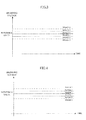
- FIG. 3 shows the relationship between machining voltage values of the electric discharge machine 10 and assessment of machined product quality
- FIG. 4 shows the relationship between machining current values and assessment of machined product quality.
- the bold solid line denotes a reference value representing a voltage optimal as machining voltage.
- the machining voltage falls within "region 1" between the bold solid line and the broken line, representing a predetermined range around the reference value, the machining voltage is assessed as “non-defective products (no inspection required)".
- the machining voltage is assessed as "inspection required”.
- the machining voltage is assessed as "defective products”.
- the assessment focuses on whether the machining voltage falls within either region 2 or 3, which are outside the broken line; when the machining voltage falls within region 1 and is assessed as “non-defective products (no inspection required)", physical quantity values at the time are not stored.
- region 2 When the machining voltage falls within region 2 and is assessed as “inspection required”, only simple data enough to indicate the necessity of inspection is stored, rather than storing many kinds of data.
- region 3 When the machining voltage falls within region 3 and is assessed as “defective products”, the machining voltage as well as other data are stored in order to determine the cause of the defectiveness.
- machining voltage falls within region 2 and is assessed as "inspection required”
- only the machining voltage value obtained by monitoring is stored or a flag value indicating that the result of assessment was region 2 is stored.
- the machining voltage falls within region 3 and is assessed as “defective products”
- the machining current, machining speed, the current positions of axes and the like at the time are also stored in addition to the machining voltage value obtained by monitoring.
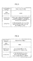
- FIGs. 5 and 6 show the relationship between the result of assessment on machining voltage and data to be stored in response to the result.
- FIG. 5 only the machining voltage value obtained by monitoring is stored when the assessment result is "inspection required"; while in FIG. 6 a flag value indicating the assessment result is stored when the result is "inspection required”.
- measuring of the machining current of the electric discharge machine 10 and assessing machined product quality based on the measured value is also concurrently performed in a similar manner.
- machining current falls within region 2 and is assessed as "inspection required”
- only the machining current value obtained by monitoring is stored or a flag value indicating that the result of assessment was region 2 is stored.
- the value of the physical quantity that was assessed as inspection required may be stored or different flags may be prepared for the kinds of physical quantities that were assessed as inspection required.
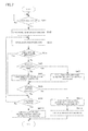
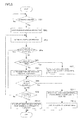
- Step SA1 Whether machining has started or not is determined. If machining has started, the flow proceeds to step SA2.
- Step SA2 Stored monitoring information that has been stored during previous monitoring is cleared.
- Step SA3 Monitoring information such as machining voltage and machining current is acquired.
- Step SA4 Whether or not data in the acquired monitoring information falls within a predefined range of "non-defective products" is determined. If the data is within the range of "non-defective products" (Yes), the flow proceeds to step SA9. If the data is outside the range of "non-defective products" (No), the flow proceeds to step SA5.
- Step SA5 Whether or not data in the monitoring information acquired in step SA3 falls within a predefined range of "inspection required” is determined. If the data is within the range of "inspection required” (Yes), the flow proceeds to step SA7. If the data is outside the range of "inspection required” (No), the flow proceeds to step SA6.
- Step SA6 The acquired data is determined to be "defective products", and the machining voltage as well as the machining current, machining speed, and/or the current positions of axes at the time are stored in the numerical controller 11 as monitoring information.
- Step SA7 Only simple data indicative of "inspection required" (e.g., only the values of the physical quantities that were assessed as "inspection required") are stored in the numerical controller 11.
- Step SA8 Whether or not the data stored in the numerical controller 11 has exceeded the storage capacity is determined. If the storage capacity has not been exceeded (No), the flow proceeds to step SA9. If the storage capacity has been exceeded (Yes), the flow proceeds to step SA11.
- Step SA9 Whether machining by the electric discharge machine has completed is determined. If machining has completed (Yes), the flow proceeds to step SA10. If machining has not completed yet, the flow returns to step SA3 to continue monitoring.
- Step SA10 In response to completion of machining, monitoring information stored in the numerical controller 11, such as machining voltage, machining current, machining speed, the current positions of axes, are sent to the computer 40 from the numerical controller 11, whereupon the process ends.
- monitoring information stored in the numerical controller 11 such as machining voltage, machining current, machining speed, the current positions of axes
- Step SA11 As the data storage capacity of the numerical controller 11 has been reached, monitoring information stored in the numerical controller 11, such as machining voltage, machining current, machining speed, the current positions of axes, are sent to the computer 40 from the numerical controller 11.
- Step SA12 An alarm indicating that data in the numerical controller 11 goes beyond the storage capacity is displayed on the display 16 of the numerical controller 11, the machining operation of the electric discharge machine is stopped, and the process is terminated.
- FIG. 8 is a flowchart illustrating the process of storing a flag value indicative of the assessment result when the result of machining voltage assessment is "inspection required".
- steps SB1 through SB12 shown in the flowchart of FIG. 8 is substantially the same as processing in steps SA1 through SA12 in the flowchart of FIG. 7
- the processing in step SB7 in FIG. 8 is different from the processing in step SA7 of FIG. 7 .
- FIG. 7 when data is determined to fall within a range of "inspection required" in step SA5 and then the flow proceeds to step SA7, only simple data indicative of "inspection required" (e.g., only the values of the physical quantity that were assessed as "inspection required”) is stored in the numerical controller 11; whereas in FIG.
- step SB4 when data is determined to fall within a range of "inspection required" in step SB4 and then the flow proceeds to step SB7, a flag value indicating which physical quantity was assessed as "inspection required” is stored in the numerical controller 11 as data indicative of "inspection required".
- monitoring information for machining voltage and machining current is sorted into three ranges, namely "region 1" (with assessment result “non-defective products”), "region 2" (with assessment result “inspection required”), and “region 3” (with assessment result “defective products”).
- region 1 with assessment result "non-defective products”
- region 2 with assessment result "inspection required”
- region 3 with assessment result “defective products”
- the range of "region 2" may be subdivided into a range of "region 2A” (with assessment result "inspection required 1") and a range of "region 2B” (with assessment result "inspection required 2") as shown in FIG.
- the monitoring range is specified by defining a reference value for the machining voltage or current and setting predetermined widths above and below the reference value to establish assessment regions. Instead of setting such a reference value, the monitoring range may be specified by establishing upper and lower limit values.
- the machining voltage and all of other monitoring information including machining current, machining speed, and current positions of axes are stored in the numerical controller 11. It is not necessarily required to store all kinds of monitoring information, however; different data may be stored according to the type of data that falls outside the predetermined range. For example, in a case where monitored data is water temperature, only the time at which the water temperature fell outside its monitoring range may be stored.
- the data is sent from the numerical controller 11 to the computer 40 when machining has finished, which is advantageous in that data for the whole machining process can be sent after the machining ends.
- the invention is not limited thereto however; data may be sent during a machining operation from the numerical controller 11 to the computer 40 through an operator's control or an instruction from a program, or in a case of multiple machining operations for multiple shapes, data may be sent on each performance of a certain number of machining operations for each of the shapes.
Landscapes
- Engineering & Computer Science (AREA)
- Human Computer Interaction (AREA)
- Manufacturing & Machinery (AREA)
- Physics & Mathematics (AREA)
- General Physics & Mathematics (AREA)
- Automation & Control Theory (AREA)
- Mechanical Engineering (AREA)
- Electrical Discharge Machining, Electrochemical Machining, And Combined Machining (AREA)
- Numerical Control (AREA)
- Testing And Monitoring For Control Systems (AREA)
Applications Claiming Priority (1)
| Application Number | Priority Date | Filing Date | Title |
|---|---|---|---|
| JP2012204561A JP5642748B2 (ja) | 2012-09-18 | 2012-09-18 | 放電加工機のデータ収集システム |
Publications (3)
| Publication Number | Publication Date |
|---|---|
| EP2708966A2 true EP2708966A2 (de) | 2014-03-19 |
| EP2708966A3 EP2708966A3 (de) | 2017-12-13 |
| EP2708966B1 EP2708966B1 (de) | 2020-01-01 |
Family
ID=49080767
Family Applications (1)
| Application Number | Title | Priority Date | Filing Date |
|---|---|---|---|
| EP13182506.9A Active EP2708966B1 (de) | 2012-09-18 | 2013-08-30 | Datenerfassungssystem für Funkenerosionsmaschinen |
Country Status (4)
| Country | Link |
|---|---|
| US (1) | US9669479B2 (de) |
| EP (1) | EP2708966B1 (de) |
| JP (1) | JP5642748B2 (de) |
| CN (1) | CN103658882B (de) |
Cited By (1)
| Publication number | Priority date | Publication date | Assignee | Title |
|---|---|---|---|---|
| CN116033991A (zh) * | 2020-09-15 | 2023-04-28 | 三菱电机株式会社 | 学习装置、放电加工机及学习方法 |
Families Citing this family (9)
| Publication number | Priority date | Publication date | Assignee | Title |
|---|---|---|---|---|
| US4726333A (en) | 1986-11-28 | 1988-02-23 | Caterpillar Inc. | Glow plug alternator control |
| CN104460520A (zh) * | 2014-10-30 | 2015-03-25 | 苏州市宝玛数控设备有限公司 | 一种用于慢走丝电火花线切割机床的监控软件 |
| CN104625276B (zh) * | 2014-12-04 | 2017-07-21 | 宁波市华正信息技术有限公司 | 一种火花机在线运行参数实时监控系统及其监控方法 |
| JP2016200928A (ja) | 2015-04-09 | 2016-12-01 | ファナック株式会社 | 工作機械の管理システム |
| JP6386523B2 (ja) * | 2016-12-15 | 2018-09-05 | ファナック株式会社 | Nandフラッシュメモリの寿命を予測する機械学習装置、寿命予測装置、数値制御装置、生産システム、及び機械学習方法 |
| JP6549650B2 (ja) * | 2017-07-28 | 2019-07-24 | ファナック株式会社 | 工作機械の管理システム |
| JP6558818B1 (ja) * | 2018-10-19 | 2019-08-14 | 株式会社ソディック | 放電加工装置 |
| CN113608498A (zh) * | 2021-05-26 | 2021-11-05 | 爱欧意科技无锡有限公司 | 一种设备状态智能管理系统及其管理方法 |
| US20250199502A1 (en) * | 2022-03-01 | 2025-06-19 | Fanuc Corporation | Data collecting device and computer-readable storage medium |
Citations (2)
| Publication number | Priority date | Publication date | Assignee | Title |
|---|---|---|---|---|
| JP4047544B2 (ja) | 1998-05-12 | 2008-02-13 | 三菱電機株式会社 | 放電加工機用数値制御装置及び放電加工機用数値制御システム |
| JP4137384B2 (ja) | 1998-12-02 | 2008-08-20 | 三菱電機株式会社 | 放電加工機の加工状態良否判定装置 |
Family Cites Families (18)
| Publication number | Priority date | Publication date | Assignee | Title |
|---|---|---|---|---|
| JPS60242917A (ja) * | 1984-05-17 | 1985-12-02 | Fanuc Ltd | ワイヤ放電加工機の自動電源遮断装置 |
| JPH01289624A (ja) * | 1988-05-11 | 1989-11-21 | Hoden Seimitsu Kako Kenkyusho Ltd | 放電加工における仕上加工制御装置 |
| CN1143193C (zh) * | 1998-05-12 | 2004-03-24 | 三菱电机株式会社 | 用于放电加工机的数控装置 |
| JP2000334187A (ja) * | 1999-05-27 | 2000-12-05 | Tokai Ind Sewing Mach Co Ltd | ミシンの情報伝送装置 |
| JP2001269822A (ja) * | 2000-03-23 | 2001-10-02 | Canon Inc | 放電加工方法 |
| CN1157914C (zh) * | 2000-04-04 | 2004-07-14 | 日星特殊精密株式会社 | 用于诊断绣花机故障的故障诊断系统和方法 |
| US7797062B2 (en) * | 2001-08-10 | 2010-09-14 | Rockwell Automation Technologies, Inc. | System and method for dynamic multi-objective optimization of machine selection, integration and utilization |
| WO2003087966A1 (en) * | 2002-04-12 | 2003-10-23 | Johnson & Johnson Vision Care | Method and system for recording data monitored during the manufacture of molded ophthalmic lenses |
| CN2726796Y (zh) * | 2004-06-24 | 2005-09-21 | 青岛自动化研究所 | 一种轮胎模具花纹成型的电火花加工控制装置 |
| JP2007004601A (ja) * | 2005-06-24 | 2007-01-11 | Okuma Corp | 工作機械の運転状態監視装置 |
| US7567878B2 (en) * | 2005-12-07 | 2009-07-28 | Siemens Corporate Research, Inc. | Evaluating anomaly for one class classifiers in machine condition monitoring |
| JP2007307661A (ja) * | 2006-05-18 | 2007-11-29 | Denso Corp | ワイヤ放電加工のモニタ装置 |
| JP2008296314A (ja) * | 2007-05-30 | 2008-12-11 | Seibu Electric & Mach Co Ltd | ワイヤ放電加工装置の物理量変化状態表示システム |
| CN101751003B (zh) * | 2008-12-04 | 2013-06-12 | 鸿富锦精密工业(深圳)有限公司 | 电脑数控设备的监控系统及方法 |
| DE102009027267A1 (de) * | 2009-06-29 | 2010-12-30 | Trumpf Werkzeugmaschinen Gmbh + Co. Kg | Verfahren und Vorrichtung zur vereinfachten Fehlerverarbeitung an einer Werkzeugmaschine |
| CN101791730A (zh) * | 2010-01-19 | 2010-08-04 | 苏州新火花机床有限公司 | 一种用于电火花小孔加工的数字脉冲电源 |
| US20120156963A1 (en) * | 2010-12-20 | 2012-06-21 | Caterpillar Inc. | Method of Monitoring Gear Grinding Operations |
| JP2013186740A (ja) * | 2012-03-08 | 2013-09-19 | Fanuc Ltd | 機械の管理システム |
-
2012
- 2012-09-18 JP JP2012204561A patent/JP5642748B2/ja not_active Expired - Fee Related
-
2013
- 2013-08-30 EP EP13182506.9A patent/EP2708966B1/de active Active
- 2013-09-16 CN CN201310421173.6A patent/CN103658882B/zh not_active Expired - Fee Related
- 2013-09-17 US US14/029,282 patent/US9669479B2/en not_active Expired - Fee Related
Patent Citations (2)
| Publication number | Priority date | Publication date | Assignee | Title |
|---|---|---|---|---|
| JP4047544B2 (ja) | 1998-05-12 | 2008-02-13 | 三菱電機株式会社 | 放電加工機用数値制御装置及び放電加工機用数値制御システム |
| JP4137384B2 (ja) | 1998-12-02 | 2008-08-20 | 三菱電機株式会社 | 放電加工機の加工状態良否判定装置 |
Cited By (2)
| Publication number | Priority date | Publication date | Assignee | Title |
|---|---|---|---|---|
| CN116033991A (zh) * | 2020-09-15 | 2023-04-28 | 三菱电机株式会社 | 学习装置、放电加工机及学习方法 |
| CN116033991B (zh) * | 2020-09-15 | 2025-08-01 | 三菱电机株式会社 | 学习装置、放电加工机、学习方法及存储介质 |
Also Published As
| Publication number | Publication date |
|---|---|
| JP2014058017A (ja) | 2014-04-03 |
| US20140076855A1 (en) | 2014-03-20 |
| JP5642748B2 (ja) | 2014-12-17 |
| CN103658882A (zh) | 2014-03-26 |
| EP2708966B1 (de) | 2020-01-01 |
| US9669479B2 (en) | 2017-06-06 |
| EP2708966A3 (de) | 2017-12-13 |
| CN103658882B (zh) | 2015-09-30 |
Similar Documents
| Publication | Publication Date | Title |
|---|---|---|
| EP2708966B1 (de) | Datenerfassungssystem für Funkenerosionsmaschinen | |
| EP3864475B1 (de) | Verfahren und system zur überwachung des werkzeugverschleisses zur schätzung der restnutzungsdauer eines werkzeugs bei der bearbeitung | |
| CN106896779B (zh) | 维护时期预测系统以及维护时期预测装置 | |
| US10409302B2 (en) | Controller with coolant monitoring function | |
| JP3686336B2 (ja) | 工具摩耗データを作成し、工具摩耗量を推定し、工具の使用判定を行う方法 | |
| US11733309B2 (en) | Method and system for self-discharge prognostics for vehicle battery cells with an internal short circuit | |
| CN106249697B (zh) | 具备工具寿命管理功能的数值控制装置 | |
| EP2821870B1 (de) | Drehzahleinstellungsverfahren eines rotierenden Schneidwerkzeugs in Echtzeit und Steuerungsvorrichtung | |
| KR101945131B1 (ko) | 비정규분포 공정에서의 극소불량률 관리 방법 및 장치 | |
| JPH05329748A (ja) | 工具寿命予知装置 | |
| CN115712268A (zh) | 一种电子产品辅料自动贴合装置用故障预警系统 | |
| JP7099646B2 (ja) | 管理装置、表示処理方法および表示処理プログラム | |
| US20180157241A1 (en) | Adjustment system for machining parameter and machining parameter adjustment method | |
| US20200004221A1 (en) | Method and system for tool life monitoring and management in a cnc environment | |
| KR20140010317A (ko) | 공작 기계의 공구상태 감시시스템 및 그 방법 | |
| CN105938352B (zh) | 避免主轴过热的数值控制装置 | |
| JP4371933B2 (ja) | プラントデータ評価システムと方法、復水器真空度監視方法、データマイニング方法、および、プログラム | |
| JP2021018537A (ja) | 工作機械における診断モデルの再学習要否判定方法及び再学習要否判定装置、再学習要否判定プログラム | |
| KR20190025133A (ko) | 진동 가속도 신호를 활용한 공구 파손감지 영역 자동설정 방법 및 진동 가속도 신호를 활용한 공구 파손감지장치 | |
| US20200306913A1 (en) | Tool replacement timing management system | |
| CN109615643B (zh) | 一种基于加工画像分析的机床故障预警方法 | |
| CN120548235A (zh) | 工具折损判定条件更新装置 | |
| CN108115206B (zh) | 利用切削刀具对工件进行加工的方法、控制装置和系统 | |
| CN109877650A (zh) | 一种棒料剪切刀具寿命预测方法 | |
| CN110728059B (zh) | 一种基于工业大数据平台的板卷头尾智能分切方法及工业大数据平台 |
Legal Events
| Date | Code | Title | Description |
|---|---|---|---|
| PUAI | Public reference made under article 153(3) epc to a published international application that has entered the european phase |
Free format text: ORIGINAL CODE: 0009012 |
|
| AK | Designated contracting states |
Kind code of ref document: A2 Designated state(s): AL AT BE BG CH CY CZ DE DK EE ES FI FR GB GR HR HU IE IS IT LI LT LU LV MC MK MT NL NO PL PT RO RS SE SI SK SM TR |
|
| AX | Request for extension of the european patent |
Extension state: BA ME |
|
| PUAL | Search report despatched |
Free format text: ORIGINAL CODE: 0009013 |
|
| AK | Designated contracting states |
Kind code of ref document: A3 Designated state(s): AL AT BE BG CH CY CZ DE DK EE ES FI FR GB GR HR HU IE IS IT LI LT LU LV MC MK MT NL NO PL PT RO RS SE SI SK SM TR |
|
| AX | Request for extension of the european patent |
Extension state: BA ME |
|
| RIC1 | Information provided on ipc code assigned before grant |
Ipc: G05B 19/406 20060101AFI20171107BHEP |
|
| STAA | Information on the status of an ep patent application or granted ep patent |
Free format text: STATUS: REQUEST FOR EXAMINATION WAS MADE |
|
| 17P | Request for examination filed |
Effective date: 20180613 |
|
| RBV | Designated contracting states (corrected) |
Designated state(s): AL AT BE BG CH CY CZ DE DK EE ES FI FR GB GR HR HU IE IS IT LI LT LU LV MC MK MT NL NO PL PT RO RS SE SI SK SM TR |
|
| GRAP | Despatch of communication of intention to grant a patent |
Free format text: ORIGINAL CODE: EPIDOSNIGR1 |
|
| STAA | Information on the status of an ep patent application or granted ep patent |
Free format text: STATUS: GRANT OF PATENT IS INTENDED |
|
| GRAS | Grant fee paid |
Free format text: ORIGINAL CODE: EPIDOSNIGR3 |
|
| INTG | Intention to grant announced |
Effective date: 20191029 |
|
| GRAA | (expected) grant |
Free format text: ORIGINAL CODE: 0009210 |
|
| STAA | Information on the status of an ep patent application or granted ep patent |
Free format text: STATUS: THE PATENT HAS BEEN GRANTED |
|
| AK | Designated contracting states |
Kind code of ref document: B1 Designated state(s): AL AT BE BG CH CY CZ DE DK EE ES FI FR GB GR HR HU IE IS IT LI LT LU LV MC MK MT NL NO PL PT RO RS SE SI SK SM TR |
|
| REG | Reference to a national code |
Ref country code: GB Ref legal event code: FG4D |
|
| REG | Reference to a national code |
Ref country code: CH Ref legal event code: EP Ref country code: CH Ref legal event code: NV Representative=s name: DR. LUSUARDI AG, CH Ref country code: AT Ref legal event code: REF Ref document number: 1220566 Country of ref document: AT Kind code of ref document: T Effective date: 20200115 |
|
| REG | Reference to a national code |
Ref country code: IE Ref legal event code: FG4D |
|
| REG | Reference to a national code |
Ref country code: DE Ref legal event code: R096 Ref document number: 602013064538 Country of ref document: DE |
|
| REG | Reference to a national code |
Ref country code: NL Ref legal event code: MP Effective date: 20200101 |
|
| REG | Reference to a national code |
Ref country code: LT Ref legal event code: MG4D |
|
| PG25 | Lapsed in a contracting state [announced via postgrant information from national office to epo] |
Ref country code: PT Free format text: LAPSE BECAUSE OF FAILURE TO SUBMIT A TRANSLATION OF THE DESCRIPTION OR TO PAY THE FEE WITHIN THE PRESCRIBED TIME-LIMIT Effective date: 20200527 Ref country code: NO Free format text: LAPSE BECAUSE OF FAILURE TO SUBMIT A TRANSLATION OF THE DESCRIPTION OR TO PAY THE FEE WITHIN THE PRESCRIBED TIME-LIMIT Effective date: 20200401 Ref country code: RS Free format text: LAPSE BECAUSE OF FAILURE TO SUBMIT A TRANSLATION OF THE DESCRIPTION OR TO PAY THE FEE WITHIN THE PRESCRIBED TIME-LIMIT Effective date: 20200101 Ref country code: FI Free format text: LAPSE BECAUSE OF FAILURE TO SUBMIT A TRANSLATION OF THE DESCRIPTION OR TO PAY THE FEE WITHIN THE PRESCRIBED TIME-LIMIT Effective date: 20200101 Ref country code: CZ Free format text: LAPSE BECAUSE OF FAILURE TO SUBMIT A TRANSLATION OF THE DESCRIPTION OR TO PAY THE FEE WITHIN THE PRESCRIBED TIME-LIMIT Effective date: 20200101 Ref country code: NL Free format text: LAPSE BECAUSE OF FAILURE TO SUBMIT A TRANSLATION OF THE DESCRIPTION OR TO PAY THE FEE WITHIN THE PRESCRIBED TIME-LIMIT Effective date: 20200101 Ref country code: LT Free format text: LAPSE BECAUSE OF FAILURE TO SUBMIT A TRANSLATION OF THE DESCRIPTION OR TO PAY THE FEE WITHIN THE PRESCRIBED TIME-LIMIT Effective date: 20200101 |
|
| PG25 | Lapsed in a contracting state [announced via postgrant information from national office to epo] |
Ref country code: GR Free format text: LAPSE BECAUSE OF FAILURE TO SUBMIT A TRANSLATION OF THE DESCRIPTION OR TO PAY THE FEE WITHIN THE PRESCRIBED TIME-LIMIT Effective date: 20200402 Ref country code: IS Free format text: LAPSE BECAUSE OF FAILURE TO SUBMIT A TRANSLATION OF THE DESCRIPTION OR TO PAY THE FEE WITHIN THE PRESCRIBED TIME-LIMIT Effective date: 20200501 Ref country code: BG Free format text: LAPSE BECAUSE OF FAILURE TO SUBMIT A TRANSLATION OF THE DESCRIPTION OR TO PAY THE FEE WITHIN THE PRESCRIBED TIME-LIMIT Effective date: 20200401 Ref country code: LV Free format text: LAPSE BECAUSE OF FAILURE TO SUBMIT A TRANSLATION OF THE DESCRIPTION OR TO PAY THE FEE WITHIN THE PRESCRIBED TIME-LIMIT Effective date: 20200101 Ref country code: SE Free format text: LAPSE BECAUSE OF FAILURE TO SUBMIT A TRANSLATION OF THE DESCRIPTION OR TO PAY THE FEE WITHIN THE PRESCRIBED TIME-LIMIT Effective date: 20200101 Ref country code: HR Free format text: LAPSE BECAUSE OF FAILURE TO SUBMIT A TRANSLATION OF THE DESCRIPTION OR TO PAY THE FEE WITHIN THE PRESCRIBED TIME-LIMIT Effective date: 20200101 |
|
| REG | Reference to a national code |
Ref country code: DE Ref legal event code: R097 Ref document number: 602013064538 Country of ref document: DE |
|
| PG25 | Lapsed in a contracting state [announced via postgrant information from national office to epo] |
Ref country code: ES Free format text: LAPSE BECAUSE OF FAILURE TO SUBMIT A TRANSLATION OF THE DESCRIPTION OR TO PAY THE FEE WITHIN THE PRESCRIBED TIME-LIMIT Effective date: 20200101 Ref country code: SK Free format text: LAPSE BECAUSE OF FAILURE TO SUBMIT A TRANSLATION OF THE DESCRIPTION OR TO PAY THE FEE WITHIN THE PRESCRIBED TIME-LIMIT Effective date: 20200101 Ref country code: SM Free format text: LAPSE BECAUSE OF FAILURE TO SUBMIT A TRANSLATION OF THE DESCRIPTION OR TO PAY THE FEE WITHIN THE PRESCRIBED TIME-LIMIT Effective date: 20200101 Ref country code: EE Free format text: LAPSE BECAUSE OF FAILURE TO SUBMIT A TRANSLATION OF THE DESCRIPTION OR TO PAY THE FEE WITHIN THE PRESCRIBED TIME-LIMIT Effective date: 20200101 Ref country code: DK Free format text: LAPSE BECAUSE OF FAILURE TO SUBMIT A TRANSLATION OF THE DESCRIPTION OR TO PAY THE FEE WITHIN THE PRESCRIBED TIME-LIMIT Effective date: 20200101 Ref country code: RO Free format text: LAPSE BECAUSE OF FAILURE TO SUBMIT A TRANSLATION OF THE DESCRIPTION OR TO PAY THE FEE WITHIN THE PRESCRIBED TIME-LIMIT Effective date: 20200101 |
|
| PLBE | No opposition filed within time limit |
Free format text: ORIGINAL CODE: 0009261 |
|
| STAA | Information on the status of an ep patent application or granted ep patent |
Free format text: STATUS: NO OPPOSITION FILED WITHIN TIME LIMIT |
|
| REG | Reference to a national code |
Ref country code: AT Ref legal event code: MK05 Ref document number: 1220566 Country of ref document: AT Kind code of ref document: T Effective date: 20200101 |
|
| 26N | No opposition filed |
Effective date: 20201002 |
|
| REG | Reference to a national code |
Ref country code: DE Ref legal event code: R082 Ref document number: 602013064538 Country of ref document: DE Representative=s name: HL KEMPNER PATENTANWAELTE, SOLICITORS (ENGLAND, DE Ref country code: DE Ref legal event code: R082 Ref document number: 602013064538 Country of ref document: DE Representative=s name: HL KEMPNER PATENTANWALT, RECHTSANWALT, SOLICIT, DE |
|
| PG25 | Lapsed in a contracting state [announced via postgrant information from national office to epo] |
Ref country code: IT Free format text: LAPSE BECAUSE OF FAILURE TO SUBMIT A TRANSLATION OF THE DESCRIPTION OR TO PAY THE FEE WITHIN THE PRESCRIBED TIME-LIMIT Effective date: 20200101 Ref country code: AT Free format text: LAPSE BECAUSE OF FAILURE TO SUBMIT A TRANSLATION OF THE DESCRIPTION OR TO PAY THE FEE WITHIN THE PRESCRIBED TIME-LIMIT Effective date: 20200101 |
|
| PG25 | Lapsed in a contracting state [announced via postgrant information from national office to epo] |
Ref country code: PL Free format text: LAPSE BECAUSE OF FAILURE TO SUBMIT A TRANSLATION OF THE DESCRIPTION OR TO PAY THE FEE WITHIN THE PRESCRIBED TIME-LIMIT Effective date: 20200101 Ref country code: SI Free format text: LAPSE BECAUSE OF FAILURE TO SUBMIT A TRANSLATION OF THE DESCRIPTION OR TO PAY THE FEE WITHIN THE PRESCRIBED TIME-LIMIT Effective date: 20200101 |
|
| PG25 | Lapsed in a contracting state [announced via postgrant information from national office to epo] |
Ref country code: MC Free format text: LAPSE BECAUSE OF FAILURE TO SUBMIT A TRANSLATION OF THE DESCRIPTION OR TO PAY THE FEE WITHIN THE PRESCRIBED TIME-LIMIT Effective date: 20200101 |
|
| GBPC | Gb: european patent ceased through non-payment of renewal fee |
Effective date: 20200830 |
|
| PG25 | Lapsed in a contracting state [announced via postgrant information from national office to epo] |
Ref country code: LU Free format text: LAPSE BECAUSE OF NON-PAYMENT OF DUE FEES Effective date: 20200830 |
|
| REG | Reference to a national code |
Ref country code: BE Ref legal event code: MM Effective date: 20200831 |
|
| PG25 | Lapsed in a contracting state [announced via postgrant information from national office to epo] |
Ref country code: FR Free format text: LAPSE BECAUSE OF NON-PAYMENT OF DUE FEES Effective date: 20200831 |
|
| PG25 | Lapsed in a contracting state [announced via postgrant information from national office to epo] |
Ref country code: BE Free format text: LAPSE BECAUSE OF NON-PAYMENT OF DUE FEES Effective date: 20200831 Ref country code: GB Free format text: LAPSE BECAUSE OF NON-PAYMENT OF DUE FEES Effective date: 20200830 Ref country code: IE Free format text: LAPSE BECAUSE OF NON-PAYMENT OF DUE FEES Effective date: 20200830 |
|
| PG25 | Lapsed in a contracting state [announced via postgrant information from national office to epo] |
Ref country code: TR Free format text: LAPSE BECAUSE OF FAILURE TO SUBMIT A TRANSLATION OF THE DESCRIPTION OR TO PAY THE FEE WITHIN THE PRESCRIBED TIME-LIMIT Effective date: 20200101 Ref country code: MT Free format text: LAPSE BECAUSE OF FAILURE TO SUBMIT A TRANSLATION OF THE DESCRIPTION OR TO PAY THE FEE WITHIN THE PRESCRIBED TIME-LIMIT Effective date: 20200101 Ref country code: CY Free format text: LAPSE BECAUSE OF FAILURE TO SUBMIT A TRANSLATION OF THE DESCRIPTION OR TO PAY THE FEE WITHIN THE PRESCRIBED TIME-LIMIT Effective date: 20200101 |
|
| PG25 | Lapsed in a contracting state [announced via postgrant information from national office to epo] |
Ref country code: MK Free format text: LAPSE BECAUSE OF FAILURE TO SUBMIT A TRANSLATION OF THE DESCRIPTION OR TO PAY THE FEE WITHIN THE PRESCRIBED TIME-LIMIT Effective date: 20200101 Ref country code: AL Free format text: LAPSE BECAUSE OF FAILURE TO SUBMIT A TRANSLATION OF THE DESCRIPTION OR TO PAY THE FEE WITHIN THE PRESCRIBED TIME-LIMIT Effective date: 20200101 |
|
| PGFP | Annual fee paid to national office [announced via postgrant information from national office to epo] |
Ref country code: CH Payment date: 20230902 Year of fee payment: 11 |
|
| PGFP | Annual fee paid to national office [announced via postgrant information from national office to epo] |
Ref country code: DE Payment date: 20230705 Year of fee payment: 11 |
|
| REG | Reference to a national code |
Ref country code: DE Ref legal event code: R119 Ref document number: 602013064538 Country of ref document: DE |
|
| REG | Reference to a national code |
Ref country code: CH Ref legal event code: PL |
|
| PG25 | Lapsed in a contracting state [announced via postgrant information from national office to epo] |
Ref country code: CH Free format text: LAPSE BECAUSE OF NON-PAYMENT OF DUE FEES Effective date: 20240831 |
|
| PG25 | Lapsed in a contracting state [announced via postgrant information from national office to epo] |
Ref country code: DE Free format text: LAPSE BECAUSE OF NON-PAYMENT OF DUE FEES Effective date: 20250301 |