EP2716794A1 - Cellule d'électrolyse - Google Patents
Cellule d'électrolyse Download PDFInfo
- Publication number
- EP2716794A1 EP2716794A1 EP13187412.5A EP13187412A EP2716794A1 EP 2716794 A1 EP2716794 A1 EP 2716794A1 EP 13187412 A EP13187412 A EP 13187412A EP 2716794 A1 EP2716794 A1 EP 2716794A1
- Authority
- EP
- European Patent Office
- Prior art keywords
- anode
- electrode
- cathode
- electrodes
- housing
- Prior art date
- Legal status (The legal status is an assumption and is not a legal conclusion. Google has not performed a legal analysis and makes no representation as to the accuracy of the status listed.)
- Withdrawn
Links
- 239000003792 electrolyte Substances 0.000 claims abstract description 34
- 239000012528 membrane Substances 0.000 claims abstract description 33
- 125000006850 spacer group Chemical group 0.000 claims abstract description 27
- 238000005868 electrolysis reaction Methods 0.000 claims description 46
- 210000004379 membrane Anatomy 0.000 description 22
- FAPWRFPIFSIZLT-UHFFFAOYSA-M Sodium chloride Chemical compound [Na+].[Cl-] FAPWRFPIFSIZLT-UHFFFAOYSA-M 0.000 description 14
- HEMHJVSKTPXQMS-UHFFFAOYSA-M Sodium hydroxide Chemical compound [OH-].[Na+] HEMHJVSKTPXQMS-UHFFFAOYSA-M 0.000 description 14
- 239000002253 acid Substances 0.000 description 13
- XLYOFNOQVPJJNP-UHFFFAOYSA-N water Substances O XLYOFNOQVPJJNP-UHFFFAOYSA-N 0.000 description 11
- RTAQQCXQSZGOHL-UHFFFAOYSA-N Titanium Chemical compound [Ti] RTAQQCXQSZGOHL-UHFFFAOYSA-N 0.000 description 10
- 238000007789 sealing Methods 0.000 description 10
- 239000010936 titanium Substances 0.000 description 10
- 229910052719 titanium Inorganic materials 0.000 description 10
- 239000011248 coating agent Substances 0.000 description 9
- 238000000576 coating method Methods 0.000 description 9
- 239000011780 sodium chloride Substances 0.000 description 9
- 239000000243 solution Substances 0.000 description 9
- 239000003929 acidic solution Substances 0.000 description 7
- 239000012267 brine Substances 0.000 description 6
- 239000000969 carrier Substances 0.000 description 6
- HPALAKNZSZLMCH-UHFFFAOYSA-M sodium;chloride;hydrate Chemical compound O.[Na+].[Cl-] HPALAKNZSZLMCH-UHFFFAOYSA-M 0.000 description 6
- 239000003637 basic solution Substances 0.000 description 5
- MHAJPDPJQMAIIY-UHFFFAOYSA-N Hydrogen peroxide Chemical compound OO MHAJPDPJQMAIIY-UHFFFAOYSA-N 0.000 description 4
- 230000001580 bacterial effect Effects 0.000 description 4
- 239000000460 chlorine Substances 0.000 description 4
- 150000002500 ions Chemical class 0.000 description 4
- 229910052751 metal Inorganic materials 0.000 description 4
- 239000002184 metal Substances 0.000 description 4
- 229910044991 metal oxide Inorganic materials 0.000 description 4
- 150000004706 metal oxides Chemical class 0.000 description 4
- 229910052760 oxygen Inorganic materials 0.000 description 4
- QVGXLLKOCUKJST-UHFFFAOYSA-N atomic oxygen Chemical compound [O] QVGXLLKOCUKJST-UHFFFAOYSA-N 0.000 description 3
- 230000003115 biocidal effect Effects 0.000 description 3
- 239000003139 biocide Substances 0.000 description 3
- 229910052801 chlorine Inorganic materials 0.000 description 3
- HTXDPTMKBJXEOW-UHFFFAOYSA-N dioxoiridium Chemical compound O=[Ir]=O HTXDPTMKBJXEOW-UHFFFAOYSA-N 0.000 description 3
- 229910052741 iridium Inorganic materials 0.000 description 3
- GKOZUEZYRPOHIO-UHFFFAOYSA-N iridium atom Chemical compound [Ir] GKOZUEZYRPOHIO-UHFFFAOYSA-N 0.000 description 3
- 229910000457 iridium oxide Inorganic materials 0.000 description 3
- FUJCRWPEOMXPAD-UHFFFAOYSA-N lithium oxide Chemical compound [Li+].[Li+].[O-2] FUJCRWPEOMXPAD-UHFFFAOYSA-N 0.000 description 3
- 229910001947 lithium oxide Inorganic materials 0.000 description 3
- 239000000395 magnesium oxide Substances 0.000 description 3
- CPLXHLVBOLITMK-UHFFFAOYSA-N magnesium oxide Inorganic materials [Mg]=O CPLXHLVBOLITMK-UHFFFAOYSA-N 0.000 description 3
- AXZKOIWUVFPNLO-UHFFFAOYSA-N magnesium;oxygen(2-) Chemical compound [O-2].[Mg+2] AXZKOIWUVFPNLO-UHFFFAOYSA-N 0.000 description 3
- 239000007800 oxidant agent Substances 0.000 description 3
- 239000001301 oxygen Substances 0.000 description 3
- 150000003839 salts Chemical class 0.000 description 3
- ZAMOUSCENKQFHK-UHFFFAOYSA-N Chlorine atom Chemical compound [Cl] ZAMOUSCENKQFHK-UHFFFAOYSA-N 0.000 description 2
- CBENFWSGALASAD-UHFFFAOYSA-N Ozone Chemical compound [O-][O+]=O CBENFWSGALASAD-UHFFFAOYSA-N 0.000 description 2
- -1 Polyethylene Polymers 0.000 description 2
- 150000007513 acids Chemical class 0.000 description 2
- 239000003513 alkali Substances 0.000 description 2
- 150000001875 compounds Chemical class 0.000 description 2
- 230000000694 effects Effects 0.000 description 2
- 239000000463 material Substances 0.000 description 2
- 238000000034 method Methods 0.000 description 2
- 239000000203 mixture Substances 0.000 description 2
- 239000000126 substance Substances 0.000 description 2
- KZBUYRJDOAKODT-UHFFFAOYSA-N Chlorine Chemical compound ClCl KZBUYRJDOAKODT-UHFFFAOYSA-N 0.000 description 1
- UFHFLCQGNIYNRP-UHFFFAOYSA-N Hydrogen Chemical compound [H][H] UFHFLCQGNIYNRP-UHFFFAOYSA-N 0.000 description 1
- WHXSMMKQMYFTQS-UHFFFAOYSA-N Lithium Chemical compound [Li] WHXSMMKQMYFTQS-UHFFFAOYSA-N 0.000 description 1
- FYYHWMGAXLPEAU-UHFFFAOYSA-N Magnesium Chemical compound [Mg] FYYHWMGAXLPEAU-UHFFFAOYSA-N 0.000 description 1
- 239000004698 Polyethylene Substances 0.000 description 1
- 241000589517 Pseudomonas aeruginosa Species 0.000 description 1
- 241001138501 Salmonella enterica Species 0.000 description 1
- 241000191967 Staphylococcus aureus Species 0.000 description 1
- 239000012670 alkaline solution Substances 0.000 description 1
- 230000000721 bacterilogical effect Effects 0.000 description 1
- 239000003518 caustics Substances 0.000 description 1
- 239000004020 conductor Substances 0.000 description 1
- 230000001419 dependent effect Effects 0.000 description 1
- 239000000645 desinfectant Substances 0.000 description 1
- 230000000249 desinfective effect Effects 0.000 description 1
- 238000011161 development Methods 0.000 description 1
- 230000018109 developmental process Effects 0.000 description 1
- 230000005684 electric field Effects 0.000 description 1
- 238000000909 electrodialysis Methods 0.000 description 1
- 239000013505 freshwater Substances 0.000 description 1
- 230000005484 gravity Effects 0.000 description 1
- 239000001257 hydrogen Substances 0.000 description 1
- 229910052739 hydrogen Inorganic materials 0.000 description 1
- QWPPOHNGKGFGJK-UHFFFAOYSA-N hypochlorous acid Chemical compound ClO QWPPOHNGKGFGJK-UHFFFAOYSA-N 0.000 description 1
- 229910052744 lithium Inorganic materials 0.000 description 1
- 239000011777 magnesium Substances 0.000 description 1
- 229910052749 magnesium Inorganic materials 0.000 description 1
- 230000000737 periodic effect Effects 0.000 description 1
- 239000004033 plastic Substances 0.000 description 1
- 229920003023 plastic Polymers 0.000 description 1
- 229920000573 polyethylene Polymers 0.000 description 1
- 230000001681 protective effect Effects 0.000 description 1
- 238000007493 shaping process Methods 0.000 description 1
- 239000008399 tap water Substances 0.000 description 1
- 235000020679 tap water Nutrition 0.000 description 1
- 239000000080 wetting agent Substances 0.000 description 1
Images


Classifications
-
- C—CHEMISTRY; METALLURGY
- C25—ELECTROLYTIC OR ELECTROPHORETIC PROCESSES; APPARATUS THEREFOR
- C25B—ELECTROLYTIC OR ELECTROPHORETIC PROCESSES FOR THE PRODUCTION OF COMPOUNDS OR NON-METALS; APPARATUS THEREFOR
- C25B9/00—Cells or assemblies of cells; Constructional parts of cells; Assemblies of constructional parts, e.g. electrode-diaphragm assemblies; Process-related cell features
-
- C—CHEMISTRY; METALLURGY
- C02—TREATMENT OF WATER, WASTE WATER, SEWAGE, OR SLUDGE
- C02F—TREATMENT OF WATER, WASTE WATER, SEWAGE, OR SLUDGE
- C02F1/00—Treatment of water, waste water, or sewage
- C02F1/46—Treatment of water, waste water, or sewage by electrochemical methods
- C02F1/461—Treatment of water, waste water, or sewage by electrochemical methods by electrolysis
-
- C—CHEMISTRY; METALLURGY
- C25—ELECTROLYTIC OR ELECTROPHORETIC PROCESSES; APPARATUS THEREFOR
- C25B—ELECTROLYTIC OR ELECTROPHORETIC PROCESSES FOR THE PRODUCTION OF COMPOUNDS OR NON-METALS; APPARATUS THEREFOR
- C25B1/00—Electrolytic production of inorganic compounds or non-metals
- C25B1/01—Products
- C25B1/02—Hydrogen or oxygen
- C25B1/04—Hydrogen or oxygen by electrolysis of water
-
- C—CHEMISTRY; METALLURGY
- C25—ELECTROLYTIC OR ELECTROPHORETIC PROCESSES; APPARATUS THEREFOR
- C25B—ELECTROLYTIC OR ELECTROPHORETIC PROCESSES FOR THE PRODUCTION OF COMPOUNDS OR NON-METALS; APPARATUS THEREFOR
- C25B9/00—Cells or assemblies of cells; Constructional parts of cells; Assemblies of constructional parts, e.g. electrode-diaphragm assemblies; Process-related cell features
- C25B9/70—Assemblies comprising two or more cells
- C25B9/73—Assemblies comprising two or more cells of the filter-press type
-
- Y—GENERAL TAGGING OF NEW TECHNOLOGICAL DEVELOPMENTS; GENERAL TAGGING OF CROSS-SECTIONAL TECHNOLOGIES SPANNING OVER SEVERAL SECTIONS OF THE IPC; TECHNICAL SUBJECTS COVERED BY FORMER USPC CROSS-REFERENCE ART COLLECTIONS [XRACs] AND DIGESTS
- Y02—TECHNOLOGIES OR APPLICATIONS FOR MITIGATION OR ADAPTATION AGAINST CLIMATE CHANGE
- Y02E—REDUCTION OF GREENHOUSE GAS [GHG] EMISSIONS, RELATED TO ENERGY GENERATION, TRANSMISSION OR DISTRIBUTION
- Y02E60/00—Enabling technologies; Technologies with a potential or indirect contribution to GHG emissions mitigation
- Y02E60/30—Hydrogen technology
- Y02E60/36—Hydrogen production from non-carbon containing sources, e.g. by water electrolysis
Definitions
- the invention relates to an electrolytic cell according to the preamble of the independent patent claim 1.
- Diaphragm-type electrolysis cells are used, for example, to split the water into hydrogen and oxygen by means of electrochemical processes in solutions of salts.
- the generated ions are separated in the electric field and form with ions of the salt or salts acid and alkali.
- the alkalis and acids thus produced are used, for example, as a disinfectant.
- the known electro-diaphragm analyzing cell has an internal space which is divided into two chambers by a semipermeable (semipermeable) membrane, a cathode in one chamber and an anode in the other chamber.
- Each of the chambers has an inlet for a slightly saline and lime-free water and an outlet opening.
- the cathode and / or the anode are made of metal, preferably titanium, in particular pure titanium.
- the anode may carry an acid-resistant coating which prolongs the life of the electro-diaphragm cell.
- the interior of the electro-diaphragm cell is separated by the semipermeable membrane into two equal chambers.
- an electrode is present in each of the two chambers.
- a DC voltage is applied to the two electrodes.
- the electrolysis current is selected and set, for example, at a voltage of 24 volts DC (direct current) in a range up to 20 amps (typically 14 A).
- NaCl solution so-called saline brine with lime-free (softened) water is fed to the two chambers.
- an acidic solution in which, among others, the compounds and ions H 2 O, Cl 2 , HClO, HO 2 , CIO and O 3 H can be included can.
- the cathode forms a basic solution in which, among others, the compounds and ions H 2 O, NaOH, H (X), H 2 (X), OH may be included.
- the products produced with said electro-diaphragm cell are diluted and / or mixed according to the application. Important applications are to clean and sanitize.
- electrolysis cells in particular electrolysis cells with diaphragm according to DE 20 2007 004181 U , have an insufficient efficiency, which is reflected in a high power consumption and thus high operating costs.
- an object of the present invention to provide an electrolytic cell which does not have the disadvantages of the prior art.
- an electrolytic cell is to be provided which has an increased efficiency
- the efficiency of the electrolysis cell can be significantly extended.
- the electrolytic cell according to the invention comprises a housing or frame, in particular with a first housing shell and a second housing shell (14), which can be assembled over respective edge zones, can be clamped together in particular, wherein the housing shells within the edge zones have back walls for supporting electrodes, two electrodes, in particular a cathode and an anode, enclosed or supported by the housing or the frame, an electrical connection to each electrode, at least one semipermeable Membrane (diaphragm) to the arrangement, in particular arranged, between the cathode and anode, at least two spacers for arrangement, in particular arranged, on the one hand between the membrane and the cathode and on the other hand between the membrane and anode, whereby between the electrodes two separate from each other by the membrane chambers formed in each of the two chambers each having an inlet opening and an outlet opening for an electrolyte, and is characterized in particular in that a plurality of pressure
- the pressure means serve to generate a pressure on the back of at least one of the electrodes and thus a pressing force between the two electrodes.
- the pressure on the back of at least one of the electrodes and thus the pressing force between the two electrodes is independent of the clamping force between the two housing shells.
- a multiplicity of openings or pressure means preferably contains at least 6, preferably at least 10, apertures or pressure means.
- This electrolysis cell has the particular advantages that the electrolysis can be carried out most efficiently, inexpensively and safely.
- the plurality of pressure means are arranged on the rear side (i.e., on the rear side facing away from the active electrode side) of one of the two electrodes, wherein the arrangement of the pressure means is adapted in particular to the profile of the spacer or the pressure means are arranged following the course of the spacer.
- This type of arrangement of the pressure means serves to exert pressure on the sealing area edge areas of the electrode, which is in sealing contact with the spacer.
- the plurality of pressure means is expediently arranged in rows with substantially uniform distances between the pressure means arranged in a row.
- the distance from the pressure medium center to the pressure medium center of lined pressure medium is preferably in the range of 1 cm to 2 cm.
- a pressure medium is provided per 3 cm 2 to 4 cm 2 of electrode area (measured on the back of the electrode).
- the pressure means can be designed as screws, in particular as setscrews, preferably with hexagon socket.
- the thread can be made with a fine thread instead of a standard thread to give a fine adjustment.
- the housing consists at least of a first housing shell and a second housing shell, which can be assembled, wherein advantageously at least one housing shell has a recess with recessed rear wall to form a cavity which is able to accommodate at least one electrode (in whole or in part).
- the recess is bordered, so to speak, with a border zone or enclosure.
- the edge zone or enclosure advantageously has means and structures for mutual attachment of the housing shells. Suitable means include, for example, elements of a screw cap, which serve the housing shells on communicating structures, eg through holes, which in the edge zones or enclosures of two housing shells are created communicating with each other.
- At least the first housing shell is reinforced at the edge zone with a first enclosure, optionally also the second housing shell at its edge zone with a second enclosure, so that the housing shells on the enclosures, which advantageously rise above the rear walls, together form an inner cavity, which can serve as an electrode holder.
- the rear wall has a plurality of openings for receiving the pressure medium, wherein advantageously the openings are equipped with an internal thread.
- the apertures are advantageously arranged in rows with substantially uniform spacing between the apertures lined up in a row.
- the apertures are chain-like, in particular lined up in a row or alternatively two or more rows.
- the apertures are expediently arranged in the rear wall along the edge region or the side surround so as to stand in particular opposite the electrode surface edge region, so that pressure medium introduced into the apertures, in particular screwed in, presses against the back of an electrode inserted in the housing shell.
- the housing shells expediently have passage holes (55, 55 ', 56, 56') for the supply and removal of an electrolyte, the passage holes serving in particular to supply said inlet openings with electrolyte or to withdraw electrolyte through said outlet openings.
- the passage holes are advantageously placed in the recess of the respective housing shell, in particular presented to the inlet and outlet openings of the electrodes.
- the electrodes are expediently designed as plates, in particular as flat plates.
- the electrode plates preferably have at least a thickness of 2 mm, more preferably at least 3 mm, more preferably at least 3.5 mm, more preferably at least 4 mm.
- the electrodes are useful as elongated plates e.g. with a preferred aspect ratio of at least 2: 1, more preferably at least 3: 1.
- a single anode-cathode pair is expediently arranged between the first housing shell and the second housing shell.
- Housing and / or frame dimensions are preferably designed such that the distance between the anode (ie, the active anode surface) and the cathode (ie, active cathode surface) is 0.1 mm to 10 mm, preferably 0.5 mm to 5 mm, more preferably 1 mm to 3 mm.
- the distance between the anode (i.e., the anode active surface) and the cathode (i.e., cathode cathode active surface) can be set to an accuracy of ⁇ 10 ⁇ m, preferably ⁇ 1 ⁇ m, more preferably ⁇ 0.1 ⁇ m.
- the inlet openings and the outlet openings are designed as a passage (opening) in the respective electrode.
- the entrance and exit apertures of an electrode are spaced as far apart as possible (i.e., as close as possible to the ends of the electrodes when the electrodes are in the form of elongate electrode plates) to ensure the longest possible flow path and optimum flow and electrolyte throughput.
- the inlet openings of the two electrodes are preferably mirror images of the membrane facing each other and the outlet openings of the two electrodes facing each other, so that in both chambers, the electrolyte flow points in the same direction.
- the electrodes, cathode and / or anode are preferably made of metal, in particular of titanium or pure titanium.
- the anode is optionally acid-resistant coated.
- the spacers are in particular designed with flat sealing surfaces and in their shape (in particular in their ring shape) adapted to the electrode surface edge regions, ie, for example, as a rectangular, flat ring.
- the anode and possibly the cathode may have a coating, wherein advantageously the coating of the anode contains mixed oxide, preferably iridium mixed oxide or consists of mixed oxide, preferably of iridium mixed oxide. More preferred are mixed oxides of iridium, lithium and magnesium. Particular preference is given to a mixed oxide coating whose total metal oxide content is from 30 to 50% by weight of iridium oxide, to 30 to 50% by weight of lithium oxide and a balance of magnesium oxide and not more than 2% by weight of other metal oxides.
- a mixed oxide coating whose total metal oxide content is from 100% by weight to 35-45% by weight of iridium oxide, to 35-45% by weight of lithium oxide and a balance of magnesium oxide and not more than 1% by weight of other metal oxides.
- this is a coating consisting essentially of 40% by weight of iridium oxide, 40% by weight of lithium oxide and 20% by weight of magnesium oxide. used to increase performance or increase the stability.
- the coating is preferably applied multilayered. For example, at least 10 layers on top of each other, preferably at least 20 layers, more preferably at least 30 layers.
- the housing interior of the electrolysis cell which accommodates the electrodes with membrane and spacer, is expediently cuboidal, and preferably about 45 mm X 170 mm X 25 mm (191250 mm 3 ) large.
- the active areas of the anode and the cathode which are available for the electrolysis reaction are preferably approximately equal, with the area per electrode preferably measuring approximately 25 mm X 150 mm (3750 mm 2 ).
- an electrohydraulic generator which is equipped with at least one electrolysis cell described herein.
- the electrolytic cell and thus the electrohydraulic generator are particularly suitable for producing acid and alkali from NaCl brine and decalcified water.
- the electrolysis cell is advantageously designed to treat a flow rate of 60 to 100 liters per hour, preferably at least approximately 80 liters per hour.
- the inlet openings and the outlet openings are adjusted accordingly, advantageously, the cross-sectional area of the respective opening is at least 50 mm 2.
- the electrolytic cell is preferably used for the electrolysis of saline and substantially lime-free water.
- the electrolyte consists mainly of slightly salty and lime-free (i.e., softened) water.
- a 0.2% brine is used, in particular a 0.2 ° C NaCl brine.
- % refers to weight percent
- an acid solution is formed at the anode and a basic solution at the cathode.
- the resulting solutions flow advantageously through each one outlet opening in the anode chamber or in the cathode chamber.
- the electrolysis cell is used under flow conditions, in particular under continuous or periodic flow.
- fresh electrolyte expediently flows in parallel into both electrolyte spaces and is collected at the exit from the respective electrode chamber.
- the acid solution prepared with the electrolysis cell according to the invention on the anode side contains in particular ozone (03), oxygen (O 2), chlorine (Cl 2) and hydrogen peroxide (H 2 O 2), while the basic solution produced on the anode side corresponds to an aqueous sodium hydroxide solution.
- Such an acidic solution has a very strong germ-reducing effect due to the said four oxidants.
- the basic solution With its consistency as an aqueous sodium hydroxide solution, the basic solution has the properties of a very strong wetting agent that reduces the surface tension of materials.
- the action of a combination, in particular a mixture of acidic solution and basic solution results in a massively cleansing, disinfecting and germ-reducing effect.
- the cell architecture according to the invention Due to the cell architecture according to the invention, in particular the resulting flow of the electrode chambers, in particular with preferably vertical flow from bottom to top, a substantially laminar flow is generated in the electrolysis cell. This results in a particularly good yield and desirable composition of oxidants.
- the cell architecture according to the invention is a prerequisite for constant product quality.
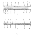
- An electrode package of an electrolytic cell as in Fig. 1 is shown schematically in a longitudinal section, includes at least two electrodes 1 and 2, in particular an anode and a cathode, each having an active electrode surface 3 and 4, and arranged between the two electrodes semipermeable membrane 5.
- Individual parts of the electrode package are in Fig. 1 (a) shown in a kind of exploded view.
- Fig. 1 (b) a clamped electrode package is shown.
- a respective spacer 6 and 6 ' in particular designed as a ring or sealing ring, inserted between the two electrodes 1 and 2 and the diaphragm 5 therebetween.
- the spacers 6 and 6 ' extend substantially along the edge (electrode surface edge region) of the active electrode surfaces 3 and 4.
- the spacers 6 and 6' substantially cover electrode surface edge regions 3 ', 3 ", 4', 4" and thereby mark the termination of the active electrode surfaces 3 and 4.
- Each of the electrolyte chambers 7 and 8 opens between the respective electrode 1 or 2 and the membrane 5, wherein the distance between each electrode and the membrane 5 by the respective spacer 6 or 6 'is set up.
- the spacers 6 and 6 ' are advantageously closed, i. as rings, executed.
- a protective film of e.g. Polyethylene be arranged, which covers the non-active region of the electrode and protects against particularly aggressive substances.
- the cathode and the anode are preferably made of metal, more preferably of titanium or pure titanium.
- the anode is preferably acid-resistant coated.
- inlet openings and outlet openings 9, 9 '10, 10' are provided. These inlet and outlet openings 9, 9 '10, 10' are advantageously applied in the electrode plates 1 and 2.
- the inlet and outlet openings 9, 9 '10, 10' as terminal At opposite ends of the respective electrolyte space 7 and 8 to create in order to ensure the most complete, uniform and efficient exchange or flow of the electrolyte.
- the connections to the power source are provided in the present example at terminal extensions 11 and 12 of the electrode plates 1 and 2.
- the contact can be generated here, for example, by a plug or terminal contact.
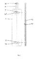
- Fig. 2 is an expedient electrode 1, as it can be used as an anode (shown here without coating) or cathode in the inventive electrolytic cell, shown Expediently, the electrode is designed as an electrode plate.
- the plate has a front side 42 and a back side 43.
- the front side 42 is designed to be in contact with an electrolyte.
- An extension 11 is used for electrical connection to a power supply.
- An electrical connection point 41 on the extension 11 may be formed, for example, as a plug receptacle.
- Inlet and outlet openings 9 and 9 ' can be designed as through holes, which advantageously - as shown - spaced apart as possible maximally spaced near the plate ends are centered, but leaving a distance between the outlet openings and the edge of the electrode plate for the support of a sealing ring or spacer 6 is provided.
- An outlet extension 44, 44 ' is aligned for this purpose, in particular transversely to the main flow direction.
- Fig. 3 is a convenient spacer 6, as it can be used in the electrolysis cell according to the invention, shown.
- the spacer is preferably designed as a closed ring with an annular contour, which is adapted to the contour of the electrode. Due to the adapted shaping of the electrode plate and spacers, they can be sandwiched on top of each other.
- An electrodialysis cell according to the invention further includes two housing shells 13 and 14, as they are eg in the Fig. 4 and 5 are shown.
- the two housing shells 13 and 14 are expediently designed as two half-shells which, when assembled, form a cell housing.
- the housing shells 13 and 14 are advantageously screwed together.
- the half shells 13 and 14 of the housing are for example made of a plastic, especially PVC.
- both housing shells 13 and 14 each have a cavity 15 and 17 which is designed such that after assembly of the housing shells 13 and 14 of the two cavities 15 and 17 (hereinafter also called subspaces) an interior space 19 is formed.
- the housing shells include rear wall 33, 35 and edge contour 25, 27, wherein the edge contour is optionally formed by a 39um charged 21, 22.
- the cavities are in particular formed relatively flat and large area.
- the side enclosures 21 and 23 of the two cavities 15 and 17 are matched to each other, so that the edge contour 25 of the cavity 15 of the first housing shell 13 coincides with the edge contour 27 of the cavity 17 of the second housing shell 14 is substantially mirror-inverted.
- the rear wall 33, 35 is preferably flat, thereby the reception of a likewise flat formed electrode is favored.
- one of the housing shells 13 may be formed with a cavity 15, while the second housing shell is designed only as a cover plate, for example without a substantial cavity (not shown pictorially).
- each rear wall 33, 35 preferably has a shape adapted to the respective electrode (eg essentially flat).
- the two side enclosures 21 and 23 of the housing shells 13 and 14 a plurality of boreholes 24, 24 'for mutual attachment of the two housing shells 13 and 14.
- the bores 24, 24' are in particular in the respective Soum charged 21, 23 of the housing shells 13, 14 created. Due to the increased execution of at least one of the Soum chargeden 21 or 23 relative to the respective rear wall 33, 35, results in the assembled state of the housing shells 13 and 14, a hollow volume, which provides space for example electrodes, membrane and electrolyte.
- a housing with interior space and inlet openings (eg inlet slots) for the two electrodes (eg electrode plates) is conceivable.
- Each of the housing shells 13 and 14, or each of the cavities 15 and 17, provides space for an electrode 1, or 2, which can be conveniently arranged on or against the rear wall 33 and 35 of the respective subspace.
- the rear walls 33 and 35 thus serve as electrode support.
- the electrodes 1 and 2 in the cavity 15 only a housing shell 13, wherein the second housing shell mainly serves as an electrode pad and ceiling shell (without substantial cavity) for the second electrode, whereby edge contours 25 in the second housing shell may be substantially eliminated or superfluous.
- the first electrode 1 and the second electrode 2 are made of electrically conductive materials.
- the electrodes may conveniently be specially coated in order to be resistant to the chemically aggressive substances produced during the electrolysis.
- at least the electrode which is used as the anode is expediently coated with an acid-resistant coating in order to be resistant to the chemically aggressive acids formed during the electrolysis.
- the housing shells 13 and 14 can be equipped with connection openings 37, 38 and 39 for the electrodes 1 and 2.
- connection openings 37, 38 and 39 for the electrodes 1 and 2.
- the two electrode extensions 11 and 12 are led outwards through said connection openings 37, 38 and / or 39 or, if e.g. Extensions 11 and 12 are missing, connecting wires are inserted.
- the outwardly guided plate extensions 11 and 12 may be provided with suitable connection points 41 of the electrodes 1 and 2, to which the power source is connected. For electrolysis, a DC voltage is conveniently connected.
- a fitting device which is provided on the housing, ie in particular on at least one of the housing shells 13 or 14, serves to hold the layers comprising at least a first electrode, a first spacer, a semipermeable membrane, a second spacer and a second electrode in this order to press and fix each other.
- further sealing rings or spacers may conveniently be additionally inserted into said position sequence of the electrode package.
- the fitting device is arranged such that it acts between the housing, in particular one of the housing shells, and at least one of the adjacent electrodes.
- the pass device is used in particular to press a first electrode plate 1 against a second electrode plate 2, wherein a press connection with the intermediate layers is formed.
- the pass device consists according to the illustrated embodiment of a plurality of threaded holes 45 and corresponding connecting elements.
- Each threaded hole 45 is designed as a through hole with an internal thread, which breaks through the housing wall.
- the threaded holes 45 are optionally within the soum charged 21 of the housing shell 13, in particular in the rear wall 35 and / or 35, applied. The breakthrough of each of the threaded bores 45 is thus at a location provided as a support for one of the electrodes.
- the apertures of the threaded bores 45 are preferably uniformly spaced from one another in a row or alternatively two or more rows each marking the edge region of the electrode support ,
- the openings are advantageously lined up along the edge region of the electrode support.
- the apertures mark the edge region of at least one of the electrode plate supports, preferably only the support of one of the two electrode plates, in particular of the first electrode plate 1, which acts as an anode plate, for example.
- the threaded holes in the rear wall 33 of the housing shells 13 or alternatively both housing shells are applied.
- Suitable fasteners include screws. Grub screws, e.g. with hexagon socket, which can be screwed in as deep as you like.
- the row of apertures 45 has substantially regular distances of 0.5 cm to 2.5 cm, preferably 1 cm to 2 cm, between successive breakthroughs from breakthrough center to breakthrough center.
- apertures 45 are in two rows, one row each along the edge region the two longitudinal side of the electrode support, ie corresponding to the two longitudinal sides of the electrode plate provided.
- the electrode plate thickness depends on the used plate material. For titanium or pure titanium electrode plates, plate thicknesses of 3 to 5 mm are preferred.
- passage holes 55, 55 ', 56, 56' are provided at a suitable location in the housing shells 13 and 14. These passage holes 55, 55 ', 56, 56' suitably correspond to the inlet and outlet openings 9, 9 ', 10, 10' of the respective electrode 1 or 2, which adjoins the rear wall 33, 35 of the cavity of the housing shell.
- the two electrodes 1 and 2 with water ie, for example, tap water or fresh water (advantageously the water is softened, especially slightly salty, but lime-free or substantially lime-free) flowed.
- water ie, for example, tap water or fresh water (advantageously the water is softened, especially slightly salty, but lime-free or substantially lime-free) flowed.
- an acid solution Anostel®
- Cathostel® alkaline solution
- the preferred current for the electrolyzation of decalcified water is typically in the range of 10 to 20 amps, most preferably in the range of 12 to 14 amps, more preferably 13 amps.
- the electrolysis cell according to the invention is preferably designed such that the above current intensities lead to voltages which are in the range from 20 to 30 volts, preferably in the range from 23 to 25 volts, in particular at 24 volts.
- the active areas of the diaphragm and the electrodes, as well as the flow rate, should be matched for best results.
- the distance between the diaphragm and the electrodes, which proved to be decisive for the efficiency of the cell, is adjusted according to the invention by manipulating the fitting device.
- An electrolytic cell with diaphragm, cathode and anode is used, the interior being cuboid, being approximately 45 mm X 170 mm X 25 mm (191250 mm 3 ) in size and the active surfaces of the two electrodes facing each other in parallel and each of the two Electrodes, ie the cathode and the anode, each about 25 mm X 150 mm (3750 mm 2 ) in size.
- Anode space and cathode space are separated by about half the distance between the cathode and anode through the diaphragm. Between diaphragm and anode or diaphragm and cathode a sealing ring or spacer is inserted, whereby the metal electrodes keep a distance of about 2 mm.
- a plurality of screws in the interior line the edge portions of the rear wall of one of the housing shells, i. Half of the screws (i.e., for example, 11 screws) are inserted into the threads in each of two opposite longitudinal edge regions and tightened to generate pressure.
- the electrolyte used consists of NaCl brine and decalcified water at room temperature.
- the flow rate per unit time through the electrolysis cell is 60 to 100 liters per hour, preferably at least approximately 80 liters per hour.
- a DC current of 13 amperes is applied, with a flow rate per unit time through the electrolysis cell of approximately 80 liters per hour, i. 40 liters per hour on each side (i.e., on the cathode side and the anode side of the electrolysis cell).
- An electrolytic cell according to Example 1 is equipped with a titanium cathode and a coated titanium anode, wherein the anode is coated with an iridium lithium magnesium mixed oxide 35 times.
- an acidic solution having a pH of about 2.5 is obtained on the anode side, which, inter alia, the oxidants ozone (03), oxygen (02), chlorine (Cl2) and hydrogen peroxide Contains (H2O2).
- an aqueous sodium hydroxide solution having a pH of about 12 is obtained.
- biocide contact time Bacterial positive carriers / 80 carriers tested 1 30 sec 80/80 1 30 sec 78/80 1 30 sec 80/80 1 2 min 77/80 1 2 min 61/80 1 2 min 3/80 1 5 min 0/80 1 5 min 0/80 1 5 min 0/80 1 10 min 0/80 1 10 min 0/80 1 10 min 0/80 biocide contact time Bacterial positive carriers / 80 carriers tested 2 30 sec 80/80 2 30 sec 80/80 2 30 sec 80/80 2 2 min 79/80 2 2 min 5/80 2 2 min 49/80 2 5 min 1/80 2 5 min 2/80 2 5 min 1/80 2 10 min 1/80 2 10 min 0/80 2 10 min 1/80 biocide contact time Bacterial positive carriers / 80 carriers tested 3 30 sec 79/80 3 30 sec 80/80 3 30 sec 70/80 3 2 min 27/80 3 2 min 30/80 3 2 min 50/80 3 5 min 0/80 3 5 min
Landscapes
- Chemical & Material Sciences (AREA)
- Organic Chemistry (AREA)
- Chemical Kinetics & Catalysis (AREA)
- Electrochemistry (AREA)
- Engineering & Computer Science (AREA)
- Materials Engineering (AREA)
- Metallurgy (AREA)
- Inorganic Chemistry (AREA)
- General Chemical & Material Sciences (AREA)
- Life Sciences & Earth Sciences (AREA)
- Hydrology & Water Resources (AREA)
- Environmental & Geological Engineering (AREA)
- Water Supply & Treatment (AREA)
- Electrolytic Production Of Non-Metals, Compounds, Apparatuses Therefor (AREA)
Applications Claiming Priority (1)
| Application Number | Priority Date | Filing Date | Title |
|---|---|---|---|
| CH01856/12A CH707059A1 (de) | 2012-10-04 | 2012-10-04 | Elektrolyszelle. |
Publications (1)
| Publication Number | Publication Date |
|---|---|
| EP2716794A1 true EP2716794A1 (fr) | 2014-04-09 |
Family
ID=49303825
Family Applications (1)
| Application Number | Title | Priority Date | Filing Date |
|---|---|---|---|
| EP13187412.5A Withdrawn EP2716794A1 (fr) | 2012-10-04 | 2013-10-04 | Cellule d'électrolyse |
Country Status (2)
| Country | Link |
|---|---|
| EP (1) | EP2716794A1 (fr) |
| CH (1) | CH707059A1 (fr) |
Cited By (1)
| Publication number | Priority date | Publication date | Assignee | Title |
|---|---|---|---|---|
| AT526232A4 (de) * | 2023-05-17 | 2024-01-15 | Andritz Ag Maschf | Elektrolysezelle und Elektrolysevorrichtung mit einer Elektrolysezelle |
Citations (5)
| Publication number | Priority date | Publication date | Assignee | Title |
|---|---|---|---|---|
| DE4227732A1 (de) * | 1992-08-21 | 1994-02-24 | Fischer Labor Und Verfahrenste | Elektrolysezelle, insbesondere zur Ozonerzeugung |
| JP3040621B2 (ja) * | 1992-12-18 | 2000-05-15 | 三菱重工業株式会社 | 固体高分子水電解セル構造体 |
| JP2002292370A (ja) * | 2001-01-23 | 2002-10-08 | Silver Seiko Ltd | オゾン水製造装置 |
| DE202007004181U1 (de) | 2006-11-22 | 2007-08-02 | Biostel Schweiz Ag | Generatorzelle und elektrochemischer Generator mit der Generatorzelle |
| WO2013161699A1 (fr) * | 2012-04-27 | 2013-10-31 | 日科ミクロン株式会社 | Dispositif de production d'eau ozonisée |
Family Cites Families (6)
| Publication number | Priority date | Publication date | Assignee | Title |
|---|---|---|---|---|
| JP2652609B2 (ja) * | 1993-05-31 | 1997-09-10 | ミズ株式会社 | 電解水生成装置 |
| US5427658A (en) * | 1993-10-21 | 1995-06-27 | Electrosci Incorporated | Electrolytic cell and method for producing a mixed oxidant gas |
| JP3606932B2 (ja) * | 1994-12-30 | 2005-01-05 | 石福金属興業株式会社 | 電解用複合電極 |
| CA2385847C (fr) * | 1999-09-27 | 2009-01-06 | Shinko Pantec Co., Ltd. | Electrode plane pour dispositif d'hydroelectrolyse, ensemble de ces electrodes, membrane electrolytique solide, et element electrolytique |
| JP2001341979A (ja) * | 2000-06-06 | 2001-12-11 | Nkk Corp | 自動クレーンおよびその同調運転方法 |
| JP4227736B2 (ja) * | 2001-04-04 | 2009-02-18 | 三菱重工業株式会社 | 固体高分子水電解セル構造体 |
-
2012
- 2012-10-04 CH CH01856/12A patent/CH707059A1/de not_active Application Discontinuation
-
2013
- 2013-10-04 EP EP13187412.5A patent/EP2716794A1/fr not_active Withdrawn
Patent Citations (5)
| Publication number | Priority date | Publication date | Assignee | Title |
|---|---|---|---|---|
| DE4227732A1 (de) * | 1992-08-21 | 1994-02-24 | Fischer Labor Und Verfahrenste | Elektrolysezelle, insbesondere zur Ozonerzeugung |
| JP3040621B2 (ja) * | 1992-12-18 | 2000-05-15 | 三菱重工業株式会社 | 固体高分子水電解セル構造体 |
| JP2002292370A (ja) * | 2001-01-23 | 2002-10-08 | Silver Seiko Ltd | オゾン水製造装置 |
| DE202007004181U1 (de) | 2006-11-22 | 2007-08-02 | Biostel Schweiz Ag | Generatorzelle und elektrochemischer Generator mit der Generatorzelle |
| WO2013161699A1 (fr) * | 2012-04-27 | 2013-10-31 | 日科ミクロン株式会社 | Dispositif de production d'eau ozonisée |
Cited By (2)
| Publication number | Priority date | Publication date | Assignee | Title |
|---|---|---|---|---|
| AT526232A4 (de) * | 2023-05-17 | 2024-01-15 | Andritz Ag Maschf | Elektrolysezelle und Elektrolysevorrichtung mit einer Elektrolysezelle |
| AT526232B1 (de) * | 2023-05-17 | 2024-01-15 | Andritz Ag Maschf | Elektrolysezelle und Elektrolysevorrichtung mit einer Elektrolysezelle |
Also Published As
| Publication number | Publication date |
|---|---|
| CH707059A1 (de) | 2014-04-15 |
Similar Documents
| Publication | Publication Date | Title |
|---|---|---|
| DE69412181T2 (de) | Vorrichtung zur Erzeugung von elektrolysiertem Wasser | |
| DE112013000327B4 (de) | Elektrolysebad zur Herstellung von saurem Wasser und dessen Verwendung | |
| DE861693C (de) | Verfahren und Vorrichtung zum Elektrodialysieren von Fluessigkeiten | |
| DE102014203374B4 (de) | Elektrodenanordnung und Verfahren zum elektrochemischen Herstellen von elektrolysiertem Wasser | |
| DE2616614C2 (de) | Elektrolyseeinrichtung | |
| DE69107992T2 (de) | Verfahren zur elektrolytischen Herstellung von Ozon und Vorrichtung dazu. | |
| DE102012214942A1 (de) | Kontinuierliches Generatorgerät für elektrolysiertes oxidiertes/reduziertes Wasser | |
| DE60302610T2 (de) | Ionenaustauschmembran-Elektrolyseur | |
| DE1299608B (de) | Verfahren und Vorrichtung zur elektrolytischen Entfernung von Spuren von Metallen aus nichtmetallischen waessrigen Salzloesungen | |
| DE2806441A1 (de) | Verfahren zur herstellung von natriumhypochlorit | |
| DE1293481T1 (de) | Elektrolysezelle zur Herstellung von anodischem Wasser für Flächenreinigung oder Behandlung, Verfahren zu Herstellung dieses Wassers und dessen Verwendung | |
| DE19540469A1 (de) | Vorrichtung zur Erzeugung von elektrolytisch ionisiertem Wasser | |
| EP0168600B1 (fr) | Electrolyseur bipolaire avec cathode à diffusion de gaz | |
| DE2856882A1 (de) | Vorrichtung zum elektrolysieren und verfahren zum herstellen von chlor durch elektrolysieren | |
| EP3110764B1 (fr) | Appareil avec des électrodes pour le traitement électrochimique d'un fluide | |
| EP2029492B1 (fr) | Dispositif pour le traitement électrochimique d'eau | |
| EP2847366A1 (fr) | Cellule d'électrolyse, destinée à être utilisée en particulier dans une installation permettant de produire une solution saline activée de manière électrochimique, et installation comprenant un certain nombre de cellules d'électrolyse de ce type | |
| DE2303589A1 (de) | Elektrolytische zellenanordnungen und chemische herstellungsverfahren | |
| WO2008061546A1 (fr) | Cellule génératrice et générateur électrochimique avec la cellule génératrice | |
| EP0322478A1 (fr) | Procédé et dispositif pour le traitement de l'eau par l'oxydation anodique, spécialement pour la production d'eau potable stérile | |
| EP2716794A1 (fr) | Cellule d'électrolyse | |
| DE2645121A1 (de) | Elektrolysezelle | |
| DE2022696B2 (de) | Elektrolysezelle zur Herstellung von Adipinsäuredinitril | |
| DE10015209A1 (de) | Verfahren und Vorrichtung zur elektrochemischen Desinfektion von Wässern | |
| DE10108452C2 (de) | Elektrolyseeinrichtung |
Legal Events
| Date | Code | Title | Description |
|---|---|---|---|
| PUAI | Public reference made under article 153(3) epc to a published international application that has entered the european phase |
Free format text: ORIGINAL CODE: 0009012 |
|
| AK | Designated contracting states |
Kind code of ref document: A1 Designated state(s): AL AT BE BG CH CY CZ DE DK EE ES FI FR GB GR HR HU IE IS IT LI LT LU LV MC MK MT NL NO PL PT RO RS SE SI SK SM TR |
|
| AX | Request for extension of the european patent |
Extension state: BA ME |
|
| STAA | Information on the status of an ep patent application or granted ep patent |
Free format text: STATUS: THE APPLICATION IS DEEMED TO BE WITHDRAWN |
|
| 18D | Application deemed to be withdrawn |
Effective date: 20141010 |