WO2013161699A1 - Dispositif de production d'eau ozonisée - Google Patents
Dispositif de production d'eau ozonisée Download PDFInfo
- Publication number
- WO2013161699A1 WO2013161699A1 PCT/JP2013/061617 JP2013061617W WO2013161699A1 WO 2013161699 A1 WO2013161699 A1 WO 2013161699A1 JP 2013061617 W JP2013061617 W JP 2013061617W WO 2013161699 A1 WO2013161699 A1 WO 2013161699A1
- Authority
- WO
- WIPO (PCT)
- Prior art keywords
- anode
- housing
- cathode
- catalyst electrode
- ozone water
- Prior art date
- Legal status (The legal status is an assumption and is not a legal conclusion. Google has not performed a legal analysis and makes no representation as to the accuracy of the status listed.)
- Ceased
Links
Images


Classifications
-
- C—CHEMISTRY; METALLURGY
- C25—ELECTROLYTIC OR ELECTROPHORETIC PROCESSES; APPARATUS THEREFOR
- C25B—ELECTROLYTIC OR ELECTROPHORETIC PROCESSES FOR THE PRODUCTION OF COMPOUNDS OR NON-METALS; APPARATUS THEREFOR
- C25B1/00—Electrolytic production of inorganic compounds or non-metals
- C25B1/01—Products
- C25B1/13—Ozone
-
- C—CHEMISTRY; METALLURGY
- C02—TREATMENT OF WATER, WASTE WATER, SEWAGE, OR SLUDGE
- C02F—TREATMENT OF WATER, WASTE WATER, SEWAGE, OR SLUDGE
- C02F1/00—Treatment of water, waste water, or sewage
- C02F1/46—Treatment of water, waste water, or sewage by electrochemical methods
- C02F1/461—Treatment of water, waste water, or sewage by electrochemical methods by electrolysis
- C02F1/467—Treatment of water, waste water, or sewage by electrochemical methods by electrolysis by electrochemical disinfection; by electrooxydation or by electroreduction
- C02F1/4672—Treatment of water, waste water, or sewage by electrochemical methods by electrolysis by electrochemical disinfection; by electrooxydation or by electroreduction by electrooxydation
-
- C—CHEMISTRY; METALLURGY
- C25—ELECTROLYTIC OR ELECTROPHORETIC PROCESSES; APPARATUS THEREFOR
- C25B—ELECTROLYTIC OR ELECTROPHORETIC PROCESSES FOR THE PRODUCTION OF COMPOUNDS OR NON-METALS; APPARATUS THEREFOR
- C25B9/00—Cells or assemblies of cells; Constructional parts of cells; Assemblies of constructional parts, e.g. electrode-diaphragm assemblies; Process-related cell features
- C25B9/17—Cells comprising dimensionally-stable non-movable electrodes; Assemblies of constructional parts thereof
- C25B9/19—Cells comprising dimensionally-stable non-movable electrodes; Assemblies of constructional parts thereof with diaphragms
-
- C—CHEMISTRY; METALLURGY
- C25—ELECTROLYTIC OR ELECTROPHORETIC PROCESSES; APPARATUS THEREFOR
- C25B—ELECTROLYTIC OR ELECTROPHORETIC PROCESSES FOR THE PRODUCTION OF COMPOUNDS OR NON-METALS; APPARATUS THEREFOR
- C25B9/00—Cells or assemblies of cells; Constructional parts of cells; Assemblies of constructional parts, e.g. electrode-diaphragm assemblies; Process-related cell features
- C25B9/60—Constructional parts of cells
- C25B9/63—Holders for electrodes; Positioning of the electrodes
-
- C—CHEMISTRY; METALLURGY
- C02—TREATMENT OF WATER, WASTE WATER, SEWAGE, OR SLUDGE
- C02F—TREATMENT OF WATER, WASTE WATER, SEWAGE, OR SLUDGE
- C02F1/00—Treatment of water, waste water, or sewage
- C02F1/46—Treatment of water, waste water, or sewage by electrochemical methods
- C02F1/461—Treatment of water, waste water, or sewage by electrochemical methods by electrolysis
- C02F1/46104—Devices therefor; Their operating or servicing
- C02F1/46109—Electrodes
- C02F2001/46133—Electrodes characterised by the material
- C02F2001/46138—Electrodes comprising a substrate and a coating
- C02F2001/46142—Catalytic coating
-
- C—CHEMISTRY; METALLURGY
- C02—TREATMENT OF WATER, WASTE WATER, SEWAGE, OR SLUDGE
- C02F—TREATMENT OF WATER, WASTE WATER, SEWAGE, OR SLUDGE
- C02F2201/00—Apparatus for treatment of water, waste water or sewage
- C02F2201/46—Apparatus for electrochemical processes
- C02F2201/461—Electrolysis apparatus
- C02F2201/46105—Details relating to the electrolytic devices
- C02F2201/46115—Electrolytic cell with membranes or diaphragms
-
- C—CHEMISTRY; METALLURGY
- C02—TREATMENT OF WATER, WASTE WATER, SEWAGE, OR SLUDGE
- C02F—TREATMENT OF WATER, WASTE WATER, SEWAGE, OR SLUDGE
- C02F2201/00—Apparatus for treatment of water, waste water or sewage
- C02F2201/46—Apparatus for electrochemical processes
- C02F2201/461—Electrolysis apparatus
- C02F2201/46105—Details relating to the electrolytic devices
- C02F2201/4612—Controlling or monitoring
- C02F2201/46125—Electrical variables
- C02F2201/4614—Current
-
- C—CHEMISTRY; METALLURGY
- C02—TREATMENT OF WATER, WASTE WATER, SEWAGE, OR SLUDGE
- C02F—TREATMENT OF WATER, WASTE WATER, SEWAGE, OR SLUDGE
- C02F2201/00—Apparatus for treatment of water, waste water or sewage
- C02F2201/46—Apparatus for electrochemical processes
- C02F2201/461—Electrolysis apparatus
- C02F2201/46105—Details relating to the electrolytic devices
- C02F2201/4616—Power supply
- C02F2201/4617—DC only
-
- C—CHEMISTRY; METALLURGY
- C02—TREATMENT OF WATER, WASTE WATER, SEWAGE, OR SLUDGE
- C02F—TREATMENT OF WATER, WASTE WATER, SEWAGE, OR SLUDGE
- C02F2209/00—Controlling or monitoring parameters in water treatment
- C02F2209/23—O3
-
- C—CHEMISTRY; METALLURGY
- C25—ELECTROLYTIC OR ELECTROPHORETIC PROCESSES; APPARATUS THEREFOR
- C25B—ELECTROLYTIC OR ELECTROPHORETIC PROCESSES FOR THE PRODUCTION OF COMPOUNDS OR NON-METALS; APPARATUS THEREFOR
- C25B13/00—Diaphragms; Spacing elements
- C25B13/04—Diaphragms; Spacing elements characterised by the material
Definitions
- the present invention relates to an ozone water generator.
- ozone water has been widely used for applications such as sterilization of foods and deodorization of malodorous gases, and many examples of knowledge have begun to be published in the fields of medical care and nursing care. Also in the semiconductor manufacturing area, the feature of ozone oxidation with respect to the ultrafine structure is recognized, and the use of ozone water is essential.
- the anode water is pressed against one surface of the cation exchange membrane, and the raw material water is brought into direct contact with the electrolytic surface of the catalyst electrode formed by pressing the cathode against the other surface.
- disassembly is known (for example, refer patent document 1).
- the casing 11 is overlaid on the anode 32 and the grating 34, and the casing 11 is penetrated.
- a method of screwing the push screw 41 and pressing the anode 32 against the cation exchange membrane 31 is known.
- a raw material water supply path 5 that passes through the housing 11 and communicates with the cation exchange membrane 31 and an ozone water discharge path 6 from which the generated ozone water is discharged are formed.
- the raw water supplied from the raw water supply path 5 comes into contact with the anode 32 and the cation exchange membrane 31, and the generated ozone water is discharged from the ozone water discharge path 6.
- a cathode is disposed on the lower surface of the cation exchange membrane 31.
- a first housing A second housing overlaid on the first housing; A catalyst electrode housed in a housing chamber formed by overlapping the first housing and the second housing, The catalyst electrode is provided in the order of an anode, a cation exchange membrane, and a cathode from the first housing side, An ozone water generating device that supplies raw water to the catalyst electrode and generates ozone water by applying a DC voltage between the anode and the cathode,
- the first casing is provided with an anode supply channel that communicates with the storage chamber and supplies raw water to the anode of the catalyst electrode, and an anode discharge channel that discharges the generated generated water.
- the second casing is provided with a cathode supply channel that communicates with the storage chamber and supplies raw water to the cathode of the catalyst electrode and a cathode discharge channel that discharges the generated generated water.
- a cushion material is provided between at least one of the anode and the first casing or between the cathode and the second casing, At least one of the first housing or the second housing penetrates the first housing or the second housing and presses the cushion material toward the catalyst electrode side, or the first housing
- a pressing member that penetrates the casing or the second casing and directly presses the catalyst electrode is provided, The pressing member is disposed at a position that presses at least the center of the catalyst electrode,
- An ozone water generator is provided in which the anode, the cation exchange membrane, and the cathode are pressed against each other by pressing the catalyst electrode by the pressing member.
- a plurality of the pressing members are provided, The plurality of pressing members are arranged at equal intervals at a position where at least the central portion of the catalyst electrode is pressed.
- the cushion material is made of silicon.
- the generation efficiency of ozone water is high, and high concentration ozone water can be generated.
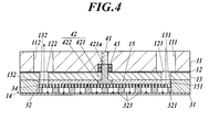
- FIG. 3 is a cross-sectional view taken along the arrow line II in FIG.
- FIG. 3 shows a cross-sectional view of the first packing material, the first cushion material, the grating, the anode, and the cation exchange membrane when cut along a cutting line II in FIG.
- FIG. 3 shows a cross-sectional view of the first packing material, the first cushion material, the grating, the anode, and the cation exchange membrane when cut along a cutting line II-II in FIG.
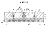
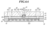
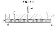
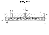
- Sectional drawing of the 1st packing material, the 1st cushion material, a grating, an anode, and a cation exchange membrane is shown. It is a prior art example, and is a sectional view of a catalyst electrode before pressure welding. It is a prior art example, and is a sectional view of a catalyst electrode at the time of pressure contact.
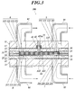
- an ozone water generating apparatus 100 includes a first housing 1, a second housing 2 superimposed on the first housing 1, and the first housing 1. And the catalyst electrode 3 accommodated in the accommodating chambers 144 and 244 formed on the overlapping surface of the second casing 2.
- the catalyst electrode 3 includes a cation exchange membrane 31, an anode 32 provided on one surface of the cation exchange membrane 31, and a cathode 33 provided on the other surface of the cation exchange membrane 31. . From the first housing 1 side, the anode 32, the cation exchange membrane 31, the cathode 33, and the second housing 2 are arranged in this order.
- the ozone water generating apparatus 100 supplies raw water to the anode 32 and the cathode 33 and applies a DC voltage between the anode 32 and the cathode 33 to generate fine ozone bubbles on the anode 32 side. Is dissolved in water to produce ozone water. Note that hydrogen is generated on the cathode 33 side, and hydrogen is dissolved in water to generate hydrogen water (cathode water).
- the first housing 1 includes a first holding plate 11 disposed on the outermost side, a first holding plate 13 disposed on the inner side of the first holding plate 11, the first holding plate 11 and the first holding. And a first sheet material 12 disposed between the plates 13.
- a first packing material 14 is provided inside the first holding plate 13. Further, the first cushion material 15, the anode 32, and the grating 34 are accommodated in a through hole (accommodating chamber 144) formed in the first packing material 14.
- the first holding plate 11 has a disk shape, and is preferably made of plastic, for example.
- An anode supply channel 111 and a discharge channel 112 are formed in the first sandwiching plate 11 so as to penetrate the front and back surfaces.
- An anode supply pipe 91 for supplying raw material water to the anode 32 from the outside is fitted into the anode supply channel 111.
- An anode discharge pipe 92 for discharging generated water (ozone water) to the outside is fitted into the anode discharge flow path 112.
- a plurality of bolt through holes 113 are formed at equal intervals around the anode supply channel 111 and the anode discharge channel 112. Further, three pressing member through holes 114 are formed at equal intervals in the central portion of the first holding plate 11.
- a pressing screw 41 is screwed into the pressing member through hole 114, and a convex portion tip 421a of the convex member 42 pressed by the screwed pressing screw 41 is fitted therein. Further, an O-ring 43 is provided on the outer periphery of the convex portion tip 421a of the convex member 42, and the O-ring 43 ensures water tightness (see FIG. 3).
- the anode supply pipe 91 is connected to, for example, a tank in which raw water is stored or is connected to a water pipe.
- the anode discharge pipe 92 is connected to, for example, a tank for storing generated ozone water, a nozzle for discharging ozone water, and the like. Examples of the raw water supplied to the anode supply pipe 91 include tap water and purified water.
- the first holding plate 13 has a disk shape that is the same size as the first holding plate 11 in plan view, and is thinner than the thickness of the first holding plate 11.
- the first holding plate 13 is preferably made of metal, for example.
- the first holding plate 13 is formed with an anode supply channel 131 and an anode discharge channel 132 at positions corresponding to the anode supply channel 111 and the anode discharge channel 112 of the first holding plate 11, respectively. ing.
- a plurality of bolt through holes 133 are formed at equal intervals around the anode supply channel 131 and the anode discharge channel 132 at positions corresponding to the bolt through holes 113 of the first holding plate 11. Yes.
- three pressing member through holes 134 are formed at equal intervals at positions corresponding to the pressing member through holes 114 of the first holding plate 11. A part of the convex portion 421 of the convex member 42 is fitted into the pressing member through hole 134.
- the first sheet material 12 is provided between the first holding plate 11 and the first holding plate 13 and is used as a packing for ensuring water tightness between the first holding plate 11 and the first holding plate 13. Function.
- the first sheet material 12 has a disk shape having the same size as the first holding plate 11 and the first holding plate 13 in plan view, and is preferably made of silicon, for example.
- the first sheet material 12 includes an anode supply channel 121 and an anode discharge channel 122 at positions corresponding to the anode supply channel 111 and the anode discharge channel 112 of the first holding plate 11, respectively. Is formed. Further, a plurality of bolt through holes 123 are formed around the anode supply channel 121 and the anode discharge channel 122.
- three pressing member through holes 124 are formed at equal intervals in the center portion of the first sheet material 12 at positions corresponding to the pressing member through holes 114 of the first holding plate 11. A part of the convex portion 421 of the convex member 42 is fitted in the pressing member through hole 124.
- the first packing material 14 is provided inside the first holding plate 13 and has a disk shape having the same size as the first holding plate 11 and the first holding plate 13, for example, fluorine. It is preferable to use a material made of a resin, pieton rubber, ethylene propylene rubber, gasket material, or the like. In addition, the hardness of the 1st packing material 14 is lower than the hardness of the anode 32 (board
- the first packing material 14 is formed with a housing chamber 144 that is a through hole having a circular shape in plan view at the center. As will be described later, the anode 32, the grating 34, and the first cushion material 15 of the catalyst electrode 3 are accommodated in the accommodation chamber 144. That is, the outer periphery of the anode 32, the grating 34, and the first cushion material 15 is surrounded and protected by the first packing material 14. A plurality of bolt through holes 143 are formed around the accommodation chamber 144.
- the first cushion material 15 is accommodated in the accommodation chamber 144 of the first packing material 14 and has a function of absorbing a load when a load is applied to the anode 32 and the grating 34.
- the first cushion material 15 has a disk shape that is smaller in plan view than the first clamping plate 11.
- the hardness of the first cushion material 15 is the same as the hardness of the first packing material 14 or lower than the hardness of the first packing material 14, and the first cushion material 15 is made of, for example, silicon (silicon rubber, silicon sponge) It is preferable that In the first cushion material 15, an anode supply channel 151 and an anode discharge channel 152 are formed at positions corresponding to the anode supply channel 131 and the anode discharge channel 132 of the first holding plate 13, respectively. Yes.
- three pressing member through holes 154 are formed at equal intervals in the center portion of the first cushion material 15 at positions corresponding to the pressing member through holes 114 of the first holding plate 11.
- the bottom portion 422 of the convex member 42 is fitted into the pressing member through hole 154.
- the push screw 41 is screwed into the upper part of the through hole 114 for the pressing member of the first holding plate 11.
- the convex member 42 has an inverted T-shape in a side sectional view, and includes a bottom portion 422 and a convex portion 421 protruding from the bottom portion 422.
- the bottom portion 422 is fitted in the pressing member through hole 154 of the first cushion material 15.
- the convex portion 421 is fitted into the pressing member through holes 134, 124, 114 of the first holding plate 13, the first sheet material 12, and the first holding plate 11, and on the outer periphery of the convex portion tip 421 a.
- An O-ring 43 is provided to ensure watertightness.
- the convex portion tip 421a of the convex member 42 is pushed downward (catalyst electrode 3 side), and a grating 34 described later is provided.
- the anode 32, the cation exchange membrane 31 and the cathode 33 are pressed and pressed.
- the second housing 2 includes a second holding plate 21 disposed on the outermost side, a second holding plate 23 disposed on the inner side of the second holding plate 21, And a second sheet material 22 disposed between the second holding plate 21 and the second holding plate 23.
- a second packing material 24 is provided inside the second holding plate 23.
- the second cushion material 25, the cathode 33, and the grating 35 are accommodated in a through hole (accommodating chamber 244) formed in the second packing material 24.
- the second sandwiching plate 21 has a disc shape, and is preferably made of plastic, for example.
- the second holding plate 21 is formed with a cathode supply channel 211 and a cathode discharge channel 212 formed so as to penetrate the front and back surfaces.
- a cathode supply pipe 93 for supplying raw material water to the cathode 33 from the outside is fitted into the cathode supply channel 211.
- a cathode discharge pipe 94 for discharging generated water (cathode water) to the outside is fitted into the cathode discharge channel 212.
- a plurality of bolt through holes 213 are formed at equal intervals around the cathode supply channel 211 and the cathode discharge channel 212.
- the cathode supply pipe 93 is connected to, for example, a tank in which raw water is stored or is connected to a water pipe. Further, the cathode discharge pipe 94 is connected to, for example, a tank for storing the generated cathode water. Examples of the raw water supplied to the cathode supply pipe 93 include tap water and purified water.
- the second holding plate 23 has a disk shape with the same size as the second holding plate 21 in plan view, and is thinner than the thickness of the second holding plate 21.
- the second holding plate 23 is preferably made of metal.
- a cathode supply channel 231 and a cathode discharge channel 232 are formed at positions corresponding to the cathode supply channel 211 and the cathode discharge channel 212 of the second holding plate 21, respectively.
- a plurality of bolt through holes 233 are formed at equal intervals around the cathode supply flow channel 231 and the cathode discharge flow channel 232 at positions corresponding to the bolt through holes 213 of the second holding plate 21. Yes.
- the second sheet material 22 is provided between the second holding plate 21 and the second holding plate 23 as a packing for ensuring watertightness between the second holding plate 21 and the second holding plate 23.
- the second sheet material 22 has a disk shape having the same size as the second holding plate 21 and the second holding plate 23 in plan view, and is preferably made of silicon, for example.
- the second sheet material 22 has a cathode supply channel 221 and a cathode discharge channel 222 at positions corresponding to the cathode supply channel 211 and the cathode discharge channel 212 of the second sandwiching plate 21, respectively. Is formed.
- a plurality of bolt through holes 223 are formed around the cathode supply channel 221 and the cathode discharge channel 222.
- the second packing material 24 is provided inside the second holding plate 23 and has a disk shape having the same size as the first holding plate 21 and the first holding plate 23 in plan view. It is preferable to use a material made of a resin, pieton rubber, ethylene propylene rubber, gasket material, or the like.
- the hardness of the second packing material 24 is preferably lower than the hardness of the cathode 33.
- the second packing material 24 is formed with a storage chamber 244 that is a through hole having a circular shape in plan view, similar to the storage chamber 144 of the first packing material 14.
- the cathode 33 and the grating 35 of the catalyst electrode 3 are accommodated in the accommodating chamber 244, respectively. That is, the outer periphery of the cathode 33 and the grating 35 is surrounded and protected by the second packing material 24.
- a plurality of bolt through holes 243 are formed around the storage chamber 244.
- the second cushion material 25 is provided between the second holding plate 23 and the second packing material 24 and has a function of absorbing a load when a load is applied to the second packing material 24 and the cathode 33. .
- the second cushion material 25 has a disk shape with the same size as the second packing material 24 in plan view, and is the same as the hardness of the second packing material 24 or lower than the hardness of the second packing material 24.
- silicon silicon rubber, silicon sponge
- the second packing material 24 functions as a stopper, the load applied to the cathode 33 can be reduced, and the effect that the crack of the cathode 33 can be prevented is obtained.
- a cathode supply channel 251 and a cathode discharge channel 252 are formed at positions corresponding to the cathode supply channel 231 and the cathode discharge channel 232 of the second holding plate 23, respectively. Yes.
- a plurality of bolt through holes 253 are formed around the cathode supply channel 251 and the cathode discharge channel 252.
- the catalyst electrode 3 includes an anode 32, a cation exchange membrane 31, a cathode 33, and gratings 34 and 35.
- 4 is a cross-sectional view of the first packing material, the first cushion material, the grating, the anode, and the cation exchange membrane when cut along the cutting line II in FIG. 2, and
- FIG. FIG. 2 is a cross-sectional view of the first packing material, the first cushion material, the grating, the anode, and the cation exchange membrane when cut along a cutting line II-II in FIG.
- the anode 32 includes a substrate 321 having a circular shape in plan view.
- a metal having an ozone generation catalyst function is used.
- platinum, gold, or a coated metal thereof from the viewpoint of good stability.
- the use of a silicon wafer is most preferable because the adhesion of diamond film formation described later is good (hard to peel).
- a diamond film is formed on at least the surface of the substrate 321 on the first housing side in terms of generating high-concentration ozone water.
- the substrate 321 is formed with a large number of through holes 323 penetrating from the front surface to the back surface.
- the diameter of the through hole 323 is preferably about ⁇ 0.5 to ⁇ 3.0.
- These through holes 323 are connected to anode supply channels 111, 121, 131, 111 for the first holding plate 11, the first sheet material 12, the first holding plate 13, and the first cushion material 15 through a grating 34 described later. 151, and further communicates with the anode discharge channels 112, 122, 132, and 152.
- the diamond film can be formed by, for example, a plasma CVD method or a thermal fermentation CVD method.
- a method for manufacturing such an anode 32 first, a plurality of through holes 323 are formed in the substrate 321 by etching, laser processing, or the like. Further, diamond is deposited on the surface of the substrate 321 at least on the first housing side by vapor deposition or the like.
- the anode 32 is housed in the housing chamber 144 of the first packing material 14 so that the outer periphery of the anode 32 is surrounded by the first packing material 14.
- the first cushion material 15 is arranged on the surface of the anode 32 opposite to the cation exchange membrane 31 via the grating 34.
- the grating 34 has a disk shape having the same size as the anode 32 in plan view.
- the grating 34 is preferably made of titanium or stainless steel.
- the grating 34 is a lattice-shaped member in which wires are welded.
- the anode 32 is sized to be fitted into the accommodation chamber 144 of the first packing material 14.
- the thickness of the anode 32 is preferably about 0.5 mm to 3.0 mm, and the thickness of the grating 34 is preferably about 0.5 mm to 1.0 mm.
- the thickness N of the first packing material 14 is preferably about 1.0 mm to 4.0 mm.
- the cation exchange membrane 31 has a circular shape in plan view and is the same as the size of the first holding plate 11 in plan view.
- a plurality of bolt through holes 313 are formed at equal intervals on the outer periphery of the cation exchange membrane 31.
- the thickness is preferably about 100 to 300 ⁇ m.
- the cathode 33 is formed of a substrate 331 having a circular shape in plan view, like the anode 32.
- a metal having an ozone generation catalyst function is used as the substrate 331.
- platinum, gold, or a coated metal thereof from the viewpoint of good stability.
- the use of a silicon wafer is most preferable because the adhesion of diamond film formation described later is good (hard to peel).
- a large number of through holes 333 are formed in the substrate 331 so as to penetrate from the front surface to the back surface.
- the diameter of the through hole 333 is preferably about ⁇ 0.5 to ⁇ 3.0.
- These through holes 333 are connected to the cathode supply channels 211, 221, 231, the second holding plate 21, the second sheet material 22, the second holding plate 23, and the second cushion material 25 through a grating 35 described later. 251 and the cathode discharge channels 212, 222, 232, and 252.
- the cathode 33 can be manufactured by the same method as that for the anode 32.
- the anode 32 and the cathode 33 are formed by forming a plurality of through holes 323 and 333 in the substrates 321 and 331 and further forming a diamond film.
- the present invention is not limited to this, and the cation exchange membrane 31 is entirely formed. If it can be overlapped with the cation exchange membrane 31 with a contact portion and a non-contact portion, it can be expanded or punched metal-like. You may use things.
- an output terminal of a power supply device (not shown) is electrically connected between the anode 32 and the cathode 33 so that a DC voltage is applied. That is, the anode 32 and the cathode 33 are connected to the power supply device via the conductive wires to the electrodes 32 and 33.
- the DC voltage to be applied is preferably in the range of 6 to 24 volts, for example.
- the anode 32 is disposed so as to be in contact with one surface of the cation exchange membrane 31, the cathode 33 is disposed so as to be in contact with the other surface, and the cation exchange membrane of the anode 32 and the cathode 33.
- Gratings 34 and 35 are arranged on the surface opposite to 31, and these are pressed to form the catalyst electrode 3.
- the second packing material 24 is overlaid, the grating 35 and the cathode 33 are housed in the housing chamber 244 formed in the second packing material 24, and the cation exchange membrane 31 and the first packing material 14 are overlaid.
- the anode 32, the grating 34, and the first cushion material 15 are accommodated in the accommodation chamber 144 formed in the first packing material 14.
- the bottom portion 422 of the convex member 42 is fitted into the pressing member through hole 154 formed in the first cushion material 15.
- the first holding plate 13 and the first sheet material 12 are overlaid on the first cushion material 15.
- the convex portion 421 of the convex member 42 is fitted into the pressing member through holes 134 and 124 formed in the first holding plate 13 and the first sheet material 12.
- the first holding plate 11 is overlaid on the first sheet material 12.
- the protruding portion tip 421a of the protruding member 42 is fitted into the pressing member through hole 114 formed in the first holding plate 11.
- the push screw 41 is screwed into the pressing member through hole 114, and the convex portion tip 421 a of the convex member 42 is pushed.
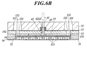
- the convex member 42 presses the anode 32, the cation exchange membrane 31 and the cathode 33 through the grating 34.
- the first cushion material 15 that has been compressed in FIG. 6A expands, and a gap is not formed between the grating 34 and the first holding plate 13. Adheres and water tightness is secured. Therefore, as shown by the dotted arrow in FIG. 6B, the raw water is reliably supplied to the anode 32 and the cation exchange membrane 31 without flowing through an extra portion or leaking to the outside.
- the push screw 41 and the convex member 42 are provided at equal intervals in the central portion of the anode 32 and the grating 34, the grating 34 is pressed uniformly, and the anode 32, the cation exchange membrane 31 and the cathode 33 are connected. Pressed uniformly.
- FIG. 6A a space is provided between the cation exchange membrane 31 and the anode 32, but actually, the anode 32 is superimposed on the cation exchange membrane 31. . That is, as shown in FIG. 6B, the cation exchange membrane 31 and the anode 32 are brought into close contact with each other by being pressed by the push screw 41. In order to make this easier to understand, FIG. However, for the sake of explanation, a space is provided between the cation exchange membrane 31 and the anode 32.
- each member is fixed by inserting and fastening the bolt M to the bolt through holes 113, 123, 133, 143, 153, 213, 223, 233, 243, 253 formed in each member,
- the ozone water generator 100 is assembled.
- the members are stacked in order from the lower member.
- the present invention is not limited to this, and the members may be stacked in order from the upper member in FIG. .
- a through hole for a pressing member is formed in the second sandwiching plate 21, the second sheet material 22, the second holding plate 23, and the second cushion material 25, and the pressing screw and the convex member are interposed through the grating 35.
- the cathode 33, the cation exchange membrane 31 and the anode 32 are in pressure contact.
- the push screw 41 and the convex member 42 described above may be provided not only on the anode side but also on both the anode and cathode sides to press the anode 32, the cation exchange membrane 31 and the cathode 33.
- the number of parentheses has shown the code
- the anode supply channel 111 formed in the first holding plate 11, the first sheet material 12, the first holding plate 13 and the first cushion material 15, 121, 131, 151 communicate with each other to form one anode supply flow path 5.
- the anode supply flow path 5 communicates with the through hole 323 of the anode 32 through the grating 34.
- anode discharge channels 112, 122, 132, 152 formed in the first holding plate 11, the first sheet material 12, the first holding plate 13, and the first cushion material 15 are in communication with each other.
- the anode discharge flow path 6 communicates with the through hole 323 of the anode 32 through the grating 34.
- the cathode supply flow channels 211, 221, 231, 251 formed in the second sandwiching plate 21, the second sheet material 22, the second holding plate 23, and the second cushion material 25 communicate with each other.
- One cathode supply flow path 7 is provided.
- the cathode supply channel 7 communicates with the through hole 333 of the cathode 33 through the grating 35.
- cathode discharge passages 212, 222, 232, and 252 formed in the second sandwiching plate 21, the second sheet material 22, the second holding plate 23, and the second cushion material 25 are connected to each other to form one line.
- the cathode discharge flow path 8 is used.
- the cathode discharge passage 8 communicates with the through hole 333 of the cathode 33 through the grating 35.
- a concentration detection sensor is provided on the downstream side of the anode discharge pipe 92.
- the concentration detection sensor includes a detection electrode (not shown), a reference electrode (not shown) serving as a reference for potential measurement, and a potentiometer (not shown) that measures the potential by connecting to one end of the detection electrode and the comparison electrode. Etc.
- the detection electrode and the comparison electrode are in contact with ozone water flowing through the anode discharge pipe 92. Then, when the detection electrode and the comparison electrode are in contact with the ozone water, the potential difference between the detection electrode and the comparison electrode due to the ozone concentration change of the detection electrode is detected, and the concentration is measured.
- the detection electrode it is preferable to use, for example, an electrode made of platinum or gold, and as the comparison electrode, silver or silver chloride is used.
- a control unit (not shown) in the ozone water generating device 100 is applied to the power supply device between the anode 32 and the cathode 33 so as to coincide with the preset ozone concentration. The amount of power to be controlled is controlled.
- a predetermined voltage is applied between the anode 32 and the cathode 33 by supplying the raw material water from the anode supply pipe 91 and the cathode supply pipe 93 and simultaneously driving the power supply device. Water is electrolyzed by this energization, ozone bubbles and oxygen bubbles are generated on the anode side, and hydrogen bubbles are generated on the cathode side.
- the raw water flows through the anode supply flow paths 111, 121, 131, 151, It flows through the through-hole 323 via the grating 34 and contacts the entire anode 32 and the cation exchange membrane 31 accommodated in the accommodation chamber 144.
- the raw material water comes into contact with the anode 32, ozone bubbles are generated, and the generated ozone bubbles are dissolved in water to become high-concentration ozone water. It flows through the anode discharge pipe 92 through 122 and 112 and is discharged to the outside.
- the raw water when the raw water is supplied from the cathode supply pipe 93, the raw water flows through the cathode supply flow paths 211, 221, 231, 251, flows through the through holes 333 a via the grating 35, and is stored in the storage chamber 244.
- the entire cathode 33 and the cation exchange membrane 31 are in contact with each other.
- hydrogen bubbles are generated, and the generated hydrogen bubbles are dissolved in water to become hydrogen water (cathode water).
- the grating 35 and the cathode discharge channels 252 and 232 are formed. , 222, 212 and then flows through the cathode discharge pipe 94 and is discharged to the outside.
- the concentration of the ozone water in the anode discharge pipe 92 is simultaneously measured by the concentration detection sensor, and the control unit adjusts the output of the power supply device so as to obtain a preset ozone concentration.
- the amount of power between 32 and the cathode 33 is controlled. As described above, ozone water having a set concentration is generated.
- the first cushion material 15 is provided between the anode 32 (grating 34) and the first housing 1 (first holding plate 13), and the first housing 1 1 is provided with a pressing member made up of a push screw 41 and a convex member 42 that penetrates the housing 1 and directly presses the catalyst electrode 3, and the pressing member is disposed at a position that presses at least the central portion of the catalyst electrode 3. Since the anode 32, the cation exchange membrane 31 and the cathode 33 are pressed against each other by the pressing of the catalyst electrode 3 by the pressing member, compared to the case where no cushion material is provided as shown in FIG.
- the pressing member directly presses the catalyst electrode 3, so that the gap formed between the first housing 1 and the catalyst electrode 3 when the catalyst electrode 3 moves downward is compressed so far.
- the first cushion material 15 that has been Are filled by Zhang watertight between the first housing 1 and the catalyst electrode 3 is secured. Therefore, the raw water is not supplied to an extra portion such as between the first housing 1 and the catalyst electrode 3 and the raw water is reliably supplied to the anode 32 and the cation exchange membrane 31 to generate ozone water. Can do. As a result, the generation efficiency of ozone water is high, and high-concentration ozone water can be generated.
- the pressing member is disposed at a position that presses at least the central portion of the catalyst electrode 3, the anode 32, the cation exchange membrane 31 and the cathode 33 can be uniformly pressed, and ozone water is also used in this respect. Production efficiency is high, and high-concentration ozone water can be produced.
- a plurality of pressing members are provided, and the plurality of pressing members are arranged at equal intervals at a position where at least the central portion of the catalyst electrode 3 is pressed, so that the catalyst electrode 3 can be pressed into contact more uniformly and with a higher concentration.
- the first cushion material 15 is made of silicon, it has high adhesiveness, can further enhance the water tightness between the first housing 1 and the catalyst electrode 3, and can improve the ozone water generation efficiency and the high concentration. Ozone water can be generated.
- the pressing member is composed of a convex member 42 that directly presses the grating 34 and a push screw 41 that presses the convex member 42, only the pressing screw 41 that directly presses the grating 34 is configured.
- the anode 32 can be pressed by the bottom portion 422 having a large area of the convex member 42, so that it can be pressed more firmly.
- the O-ring 43 on the outer periphery of the convex portion tip 421a of the convex member 42, water tightness can be maintained.
- the push screw 41 and the convex member 42 directly press the grating 34 and press the anode 32 against the cation exchange membrane 31 via the grating 34.
- the push screw 41 and the convex member 42 may directly press the first cushion material 15 and press the grating 34 and the anode 32 against the cation exchange membrane 31 through the first cushion material 15.
- the press screw 41 and the convex member 42 were used as a means to press-contact the anode 32 to the cation exchange membrane 31, only the press screw 41 is used without providing the convex member 42. Also good. Further, although the number of the push screws 41 and the convex members 42 is three each, there is no particular limitation as long as at least the central part of the anode 32 and the cation exchange membrane 31 can be pressed.
- the present invention is applied to an ozone water generating device, and can be particularly suitably used to improve the efficiency of generating ozone water and to generate high concentration ozone water.
Landscapes
- Chemical & Material Sciences (AREA)
- Engineering & Computer Science (AREA)
- Chemical Kinetics & Catalysis (AREA)
- Electrochemistry (AREA)
- Organic Chemistry (AREA)
- Materials Engineering (AREA)
- Metallurgy (AREA)
- Inorganic Chemistry (AREA)
- General Chemical & Material Sciences (AREA)
- Life Sciences & Earth Sciences (AREA)
- Hydrology & Water Resources (AREA)
- Environmental & Geological Engineering (AREA)
- Water Supply & Treatment (AREA)
- Electrolytic Production Of Non-Metals, Compounds, Apparatuses Therefor (AREA)
- Water Treatment By Electricity Or Magnetism (AREA)
- Oxygen, Ozone, And Oxides In General (AREA)
Abstract
La présente invention se rapporte à un dispositif de production d'eau ozonisée qui est pourvu d'un premier boîtier (1), d'un second boîtier (2) et d'une électrode de catalyseur (3), l'électrode de catalyseur (3) étant pourvue d'une électrode positive (32), d'une membrane échangeuse d'ions positifs (31) et d'une électrode négative (33) dans cet ordre depuis le premier boîtier, et l'eau ozonisée étant produite en alimentant en matière première aqueuse l'électrode de catalyseur (3) et en appliquant une tension continue à une électrode positive (32) et à une électrode négative (33), un canal d'arrivée d'eau d'électrode positive et un canal de décharge sont agencés sur le premier boîtier et un canal d'arrivée d'eau d'électrode négative et un canal de décharge sont agencés sur le second boîtier, un matériau de rembourrage (15) étant agencé entre l'électrode positive (32) et le premier boîtier (1) et des éléments de pression (41, 42) destinés à presser directement l'électrode de catalyseur (3) étant agencés sur le premier boîtier (1) de sorte à pénétrer dans le premier boîtier (1). Les éléments de pression (41, 42) sont disposés dans une position permettant une pression sur au moins une partie centrale de l'électrode de catalyseur (3) et l'électrode positive (32), la membrane échangeuse d'ions positifs (31) et l'électrode négative (33) sont soudées par pression sous l'effet de la pression des éléments de pression (41, 42).
Priority Applications (2)
| Application Number | Priority Date | Filing Date | Title |
|---|---|---|---|
| CN201380022327.2A CN104271808B (zh) | 2012-04-27 | 2013-04-19 | 臭氧水生成装置 |
| US14/396,683 US9920441B2 (en) | 2012-04-27 | 2013-04-19 | Ozone water generating device |
Applications Claiming Priority (2)
| Application Number | Priority Date | Filing Date | Title |
|---|---|---|---|
| JP2012-101984 | 2012-04-27 | ||
| JP2012101984A JP5069383B1 (ja) | 2012-04-27 | 2012-04-27 | オゾン水生成装置 |
Publications (1)
| Publication Number | Publication Date |
|---|---|
| WO2013161699A1 true WO2013161699A1 (fr) | 2013-10-31 |
Family
ID=47277817
Family Applications (1)
| Application Number | Title | Priority Date | Filing Date |
|---|---|---|---|
| PCT/JP2013/061617 Ceased WO2013161699A1 (fr) | 2012-04-27 | 2013-04-19 | Dispositif de production d'eau ozonisée |
Country Status (5)
| Country | Link |
|---|---|
| US (1) | US9920441B2 (fr) |
| JP (1) | JP5069383B1 (fr) |
| CN (1) | CN104271808B (fr) |
| MY (1) | MY178677A (fr) |
| WO (1) | WO2013161699A1 (fr) |
Cited By (3)
| Publication number | Priority date | Publication date | Assignee | Title |
|---|---|---|---|---|
| EP2716794A1 (fr) * | 2012-10-04 | 2014-04-09 | Biostel Schweiz Ag | Cellule d'électrolyse |
| US20160040308A1 (en) * | 2014-07-23 | 2016-02-11 | Samuel Stucki | Electrolysis cell and method for operating an electrolysis cell |
| JPWO2020075508A1 (ja) * | 2018-10-11 | 2021-02-15 | Dic株式会社 | 液晶組成物および液晶表示素子 |
Families Citing this family (18)
| Publication number | Priority date | Publication date | Assignee | Title |
|---|---|---|---|---|
| EP2697730A4 (fr) | 2011-04-15 | 2015-04-15 | Advanced Diamond Technologies Inc | Système et procédé électrochimiques destinés à une génération sur site d'oxydants sous une densité de courant élevée |
| JP5210456B1 (ja) * | 2012-11-20 | 2013-06-12 | 日科ミクロン株式会社 | 洗浄水生成装置 |
| JP5210455B1 (ja) * | 2012-11-20 | 2013-06-12 | 日科ミクロン株式会社 | 洗浄水生成装置 |
| US10239772B2 (en) * | 2015-05-28 | 2019-03-26 | Advanced Diamond Technologies, Inc. | Recycling loop method for preparation of high concentration ozone |
| JP6768273B2 (ja) * | 2015-09-04 | 2020-10-14 | 株式会社東芝 | 光電気化学反応装置 |
| JP6587152B2 (ja) * | 2016-03-30 | 2019-10-09 | パナソニックIpマネジメント株式会社 | 電解液体生成装置 |
| EP3529397A4 (fr) | 2016-10-20 | 2020-06-24 | Advanced Diamond Technologies, Inc. | Générateurs d'ozone, procédés de fabrication de générateurs d'ozone et procédés de génération d'ozone |
| DE102017107891A1 (de) * | 2017-04-12 | 2018-10-18 | Willi Bernard | Verfahren zur Steuerung einer Elektrolysezelle zur elektrolytischen Erzeugung von Ozon und eine Vorrichtung zur Desinfektion von Wasser |
| AU2018256429B2 (en) * | 2017-04-20 | 2023-04-27 | Axine Water Technologies Inc. | Electrochemical cell for wastewater treatment with improved electrical protection |
| BR112020019825A2 (pt) * | 2018-03-29 | 2021-01-05 | NorthStar Medical Radioisotopes LLC | Sistemas e métodos para célula de geração de água com ozônio com detecção integrada |
| US10774432B2 (en) * | 2018-05-16 | 2020-09-15 | Wen-Shing Shyu | Hydrogen molecule remixing device of dish-shaped electrolytic cell |
| JP7122558B2 (ja) * | 2018-07-13 | 2022-08-22 | パナソニックIpマネジメント株式会社 | 電解水生成装置 |
| JP7022918B2 (ja) * | 2018-07-13 | 2022-02-21 | パナソニックIpマネジメント株式会社 | 電解水生成装置 |
| JP7345112B2 (ja) * | 2020-02-14 | 2023-09-15 | パナソニックIpマネジメント株式会社 | 電解液体生成装置 |
| CN111254453B (zh) * | 2020-03-27 | 2025-02-07 | 广州德百顺蓝钻科技有限公司 | 一种臭氧电解室以及臭氧电解室应用模块 |
| US12012661B2 (en) | 2020-06-27 | 2024-06-18 | Aquamox Inc. | Electrolytic generators |
| CN217869114U (zh) * | 2020-08-19 | 2022-11-22 | 爱可依科技(上海)有限公司 | 一种电极片单元及臭氧发生器 |
| US20230340676A1 (en) * | 2020-10-01 | 2023-10-26 | Dentsply Sirona Inc. | Manifold compatible electrolytic cell (eo cell) with coplanar fluidic and electrical connection scheme |
Citations (4)
| Publication number | Priority date | Publication date | Assignee | Title |
|---|---|---|---|---|
| JPH08134678A (ja) * | 1994-11-11 | 1996-05-28 | V M C:Kk | オゾン水製造装置 |
| JP2002292370A (ja) * | 2001-01-23 | 2002-10-08 | Silver Seiko Ltd | オゾン水製造装置 |
| JP2006124750A (ja) * | 2004-10-27 | 2006-05-18 | Central Japan Railway Co | オゾン水生成装置 |
| JP2008279341A (ja) * | 2007-05-09 | 2008-11-20 | Nikka Micron Kk | オゾン水生成装置 |
Family Cites Families (1)
| Publication number | Priority date | Publication date | Assignee | Title |
|---|---|---|---|---|
| US5686051A (en) | 1994-11-11 | 1997-11-11 | Kabushiki Kaisha Kobe Seiko Sho | Ozone water production apparatus |
-
2012
- 2012-04-27 JP JP2012101984A patent/JP5069383B1/ja not_active Expired - Fee Related
-
2013
- 2013-04-19 WO PCT/JP2013/061617 patent/WO2013161699A1/fr not_active Ceased
- 2013-04-19 MY MYPI2014703138A patent/MY178677A/en unknown
- 2013-04-19 US US14/396,683 patent/US9920441B2/en active Active
- 2013-04-19 CN CN201380022327.2A patent/CN104271808B/zh active Active
Patent Citations (4)
| Publication number | Priority date | Publication date | Assignee | Title |
|---|---|---|---|---|
| JPH08134678A (ja) * | 1994-11-11 | 1996-05-28 | V M C:Kk | オゾン水製造装置 |
| JP2002292370A (ja) * | 2001-01-23 | 2002-10-08 | Silver Seiko Ltd | オゾン水製造装置 |
| JP2006124750A (ja) * | 2004-10-27 | 2006-05-18 | Central Japan Railway Co | オゾン水生成装置 |
| JP2008279341A (ja) * | 2007-05-09 | 2008-11-20 | Nikka Micron Kk | オゾン水生成装置 |
Cited By (4)
| Publication number | Priority date | Publication date | Assignee | Title |
|---|---|---|---|---|
| EP2716794A1 (fr) * | 2012-10-04 | 2014-04-09 | Biostel Schweiz Ag | Cellule d'électrolyse |
| US20160040308A1 (en) * | 2014-07-23 | 2016-02-11 | Samuel Stucki | Electrolysis cell and method for operating an electrolysis cell |
| US9624586B2 (en) * | 2014-07-23 | 2017-04-18 | Innovatec Gerãtetechnik GmbH | Electrolysis cell and method for operating an electrolysis cell |
| JPWO2020075508A1 (ja) * | 2018-10-11 | 2021-02-15 | Dic株式会社 | 液晶組成物および液晶表示素子 |
Also Published As
| Publication number | Publication date |
|---|---|
| CN104271808B (zh) | 2017-05-31 |
| CN104271808A (zh) | 2015-01-07 |
| JP2013226527A (ja) | 2013-11-07 |
| JP5069383B1 (ja) | 2012-11-07 |
| US9920441B2 (en) | 2018-03-20 |
| US20150129419A1 (en) | 2015-05-14 |
| MY178677A (en) | 2020-10-20 |
Similar Documents
| Publication | Publication Date | Title |
|---|---|---|
| JP5069383B1 (ja) | オゾン水生成装置 | |
| JP5232271B2 (ja) | 高圧水電解装置 | |
| JP5427129B2 (ja) | 電解電極ユニット及びこれを用いた電解水生成装置 | |
| JP6129809B2 (ja) | 差圧式高圧水電解装置 | |
| JP5639724B1 (ja) | 電解水生成装置及びその製造方法 | |
| US10053783B2 (en) | Differential pressure water electrolysis system | |
| JP2014105340A (ja) | 高圧水電解装置 | |
| JP6166237B2 (ja) | 差圧式高圧水電解装置 | |
| JP5702885B1 (ja) | 電解水生成装置 | |
| CN102803569A (zh) | 电化学装置 | |
| WO2016043134A1 (fr) | Ensemble électrode, dispositif d'électrolyse, et électrodes à utiliser dans un dispositif d'électrolyse | |
| JP5770246B2 (ja) | 高圧水電解装置 | |
| JP2017057482A (ja) | 電極体、電解装置 | |
| JP4637885B2 (ja) | オゾン水生成装置 | |
| JP4528840B2 (ja) | オゾン水生成装置 | |
| JP5451575B2 (ja) | 水電解装置 | |
| JP2015086454A (ja) | 差圧式高圧水電解装置 | |
| JP5069380B1 (ja) | オゾン水生成装置 | |
| JP2014065927A (ja) | 高圧水電解装置 | |
| JP5069379B1 (ja) | オゾン水生成装置 | |
| JP6091012B2 (ja) | 差圧式高圧水電解装置 | |
| JP6220957B1 (ja) | ダイヤモンド電極、ダイヤモンド電極の製造方法及び電解水生成装置 | |
| JP2010255029A (ja) | 電解装置 | |
| JP5048878B1 (ja) | オゾン水生成装置 | |
| JP5044228B2 (ja) | オゾン水生成装置 |
Legal Events
| Date | Code | Title | Description |
|---|---|---|---|
| 121 | Ep: the epo has been informed by wipo that ep was designated in this application |
Ref document number: 13781962 Country of ref document: EP Kind code of ref document: A1 |
|
| NENP | Non-entry into the national phase |
Ref country code: DE |
|
| WWE | Wipo information: entry into national phase |
Ref document number: 14396683 Country of ref document: US |
|
| 122 | Ep: pct application non-entry in european phase |
Ref document number: 13781962 Country of ref document: EP Kind code of ref document: A1 |