EP2720970B1 - Dispositif pour dérouler et enrouler une ou plusieurs lignes - Google Patents
Dispositif pour dérouler et enrouler une ou plusieurs lignes Download PDFInfo
- Publication number
- EP2720970B1 EP2720970B1 EP12732574.4A EP12732574A EP2720970B1 EP 2720970 B1 EP2720970 B1 EP 2720970B1 EP 12732574 A EP12732574 A EP 12732574A EP 2720970 B1 EP2720970 B1 EP 2720970B1
- Authority
- EP
- European Patent Office
- Prior art keywords
- lines
- line
- winding body
- winding
- sub
- Prior art date
- Legal status (The legal status is an assumption and is not a legal conclusion. Google has not performed a legal analysis and makes no representation as to the accuracy of the status listed.)
- Active
Links
Images
Classifications
-
- H—ELECTRICITY
- H02—GENERATION; CONVERSION OR DISTRIBUTION OF ELECTRIC POWER
- H02G—INSTALLATION OF ELECTRIC CABLES OR LINES, OR OF COMBINED OPTICAL AND ELECTRIC CABLES OR LINES
- H02G11/00—Arrangements of electric cables or lines between relatively-movable parts
- H02G11/02—Arrangements of electric cables or lines between relatively-movable parts using take-up reel or drum
-
- B—PERFORMING OPERATIONS; TRANSPORTING
- B65—CONVEYING; PACKING; STORING; HANDLING THIN OR FILAMENTARY MATERIAL
- B65H—HANDLING THIN OR FILAMENTARY MATERIAL, e.g. SHEETS, WEBS, CABLES
- B65H75/00—Storing webs, tapes, or filamentary material, e.g. on reels
- B65H75/02—Cores, formers, supports, or holders for coiled, wound, or folded material, e.g. reels, spindles, bobbins, cop tubes, cans, mandrels or chucks
- B65H75/34—Cores, formers, supports, or holders for coiled, wound, or folded material, e.g. reels, spindles, bobbins, cop tubes, cans, mandrels or chucks specially adapted or mounted for storing and repeatedly paying-out and re-storing lengths of material provided for particular purposes, e.g. anchored hoses, power cables
- B65H75/38—Cores, formers, supports, or holders for coiled, wound, or folded material, e.g. reels, spindles, bobbins, cop tubes, cans, mandrels or chucks specially adapted or mounted for storing and repeatedly paying-out and re-storing lengths of material provided for particular purposes, e.g. anchored hoses, power cables involving the use of a core or former internal to, and supporting, a stored package of material
- B65H75/44—Constructional details
- B65H75/4449—Arrangements or adaptations to avoid movable contacts or rotary couplings, e.g. by the use of an expansion chamber for a lenght of the cord or hose
-
- G—PHYSICS
- G02—OPTICS
- G02B—OPTICAL ELEMENTS, SYSTEMS OR APPARATUS
- G02B6/00—Light guides; Structural details of arrangements comprising light guides and other optical elements, e.g. couplings
- G02B6/44—Mechanical structures for providing tensile strength and external protection for fibres, e.g. optical transmission cables
- G02B6/4439—Auxiliary devices
- G02B6/4457—Bobbins; Reels
-
- B—PERFORMING OPERATIONS; TRANSPORTING
- B65—CONVEYING; PACKING; STORING; HANDLING THIN OR FILAMENTARY MATERIAL
- B65H—HANDLING THIN OR FILAMENTARY MATERIAL, e.g. SHEETS, WEBS, CABLES
- B65H2701/00—Handled material; Storage means
- B65H2701/30—Handled filamentary material
- B65H2701/33—Hollow or hose-like material
-
- B—PERFORMING OPERATIONS; TRANSPORTING
- B65—CONVEYING; PACKING; STORING; HANDLING THIN OR FILAMENTARY MATERIAL
- B65H—HANDLING THIN OR FILAMENTARY MATERIAL, e.g. SHEETS, WEBS, CABLES
- B65H2701/00—Handled material; Storage means
- B65H2701/30—Handled filamentary material
- B65H2701/34—Handled filamentary material electric cords or electric power cables
Definitions
- the present invention relates generally to devices for unwinding and winding one or more lines for uninterrupted connection between two connection points, in particular so-called line drums, such as cable drums, hose drums, etc.
- line drums such as cable drums, hose drums, etc.
- So-called cable drums (actually cable reels) have e.g. the disadvantage that the power is indeed through continuous lines, but for unwinding or rolling the connections to the drum must be separated to prevent twisting of the connected lines, since the connectors are connected to the drum and so rotate during the winding process.
- connection cable includes a extending in the axial direction of the take-up drum section.
- This section has a freely arranged in space cable spiral, which is held at their ends in each case in an opening of the take-up drum.
- the cable spiral consists of several, z. B. three to four, windings are arranged exposed in the space between the provided as a guide and holding elements openings.
- GB 691817 describes a non-contact device for simultaneously winding and unwinding electrical conductors or conduits onto a rotatable drum, wherein a portion of the conductors or conduits may be spirally guided axially within the drum.
- An object of the present invention is therefore to provide a device for unwinding and winding one or more lines for uninterrupted connection between two connection points which does not require separation of the lines during the unwinding or winding operation and at the same time permits a compact design.
- the device comprises a rotatable winding body for unwinding and winding the one or more lines.
- the conduit (s) is / are moved from the first fixed connection point in a first subsection from a fixed first position coaxial to the winding body to a second position opposite to the first position and from this second position to substantially in a plane having the first position guided with the winding body rotatable third position.
- the line (s) in the first section is / are helically guided freestanding between the first and second position and between the second and third position, wherein the second position is arranged freely rotatably independently of the winding body.
- the line (s) is / are performed by the third position in a second section to the peripheral side of the bobbin and possibly a number of windings around the winding body to the second connection point.
- the device according to the invention allows one or more lines to save space and unwind as needed without removing or twisting the connection lines attached thereto.
- the length of the helical portion between a fixed and a rotatable point in dependence on the minimum bending radius of the line (s) determines in principle the possible number of revolutions during unwinding and winding.
- the unwinding and winding one or more lines means in practice that the lines are inherently only one (so-called usable) part of their entire length and wound up wound. This usable part essentially corresponds to the portion of the lines located in the region of the winding body when the lines are completely wound on it.
- An uninterrupted connection in the sense of the invention means that the lines within the device are not interrupted by connecting elements, such as sliding contacts, rotary joints or the like, but are executed continuously from the first to the second connection points.
- the line (s) between the first and second position is / are guided in a helical manner. If multiple lines are present, they may or may not be laterally solidarized between the first and second positions, thus forming either one or more helices.
- the line (s) is additionally helically guided between the second and third position (free-standing in space).
- the second position is freely rotatably arranged independently of the winding body.
- This embodiment in principle allows a doubling of the usable length of the helical portion as compared to an embodiment in which the second and third positions are rotatable but relative to each other to the first position.
- the particular advantage is that this allows a space-saving design without much effort and that, moreover, unwanted distortions and looping are largely avoided, which significantly increases the reliability and reliability of the device over longer operating cycles.
- the second position is arranged axially offset from the first position.
- the particular advantage of an eccentric arrangement of the second relative to the first position is a better one Space utilization within the space required for the helix.
- the distance (A) between the second position and a position coaxial with the first position is preferably selected such that 0.1 d ⁇ A ⁇ 10 d, preferably 0.2 d ⁇ A ⁇ 5 d, very particularly preferably 0.5 d is ⁇ A ⁇ 2 d, where d is the mean (effective) diameter of the helix.
- the mean (effective) diameter of the bobbin (D) determines the length of the unwinding line per revolution, while the average (effective) diameter of the helix (d) largely from the minimum bending radius of the line (s), and the desired number and diameter Lines is specified.
- the average diameter of the winding body (D) is therefore chosen in practice preferably relatively large to the average diameter of the conductor carrier (d), e.g. 1.1 d ⁇ D ⁇ 100 d or more, preferably 1.5 d ⁇ D ⁇ 50 d, very particularly preferably 2 d ⁇ D ⁇ 25 d.
- the width of the conductor carrier is preferably chosen so that at least the desired number of lines can be accommodated. Another advantage of the invention is that it is even possible without further effort to subsequently insert further lines when the line carrier is sufficiently dimensioned.
- the winding body is designed as a hollow cylinder, preferably as a drum.
- the coaxially arranged flexible conductor carrier is arranged laterally offset (outside) or space-saving within this cylinder.
- Lines within the meaning of the inventions are energy, information / signal (e.g., galvanic or optical) or material carrying lines, e.g. single- or multi-core electrical cables, single or multi-core optical cables (optical fibers), single or multiple gas, liquid or solid (pressure) hoses, etc.
- the wires or channels can be parallel, twisted or coaxial .
- the term “conduit” may include both the single “vein” and the multicore or multichannel conduit itself, e.g. an electric cable.
- these lines are at least partially joined together to facilitate handling during the winding operation, e.g. at least in the up and unwindable area laterally parallel to each other, so that they form a straight line in the unwound state.
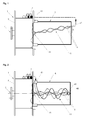
- the in the Fig. 1 for illustration shown device 1 for unwinding and winding one or more lines 2 comprises a rotatable winding body, here in the form of a drum 3.
- the device shown leads the lines from a fixed first connection point 7 in a first partial section from a first position 41 via a second position 42 to a third position 43.
- the helix 44 is provided between the first 41 and the second position 42.
- Position 42 is in Fig. 1 not arranged coaxially with the drum 3, but at a distance A.
- the helix 44 is arranged laterally of the drum 3 and protected by a housing 5.
- the housing 5 is fixed to the rotatable drum 3 in this case.
- the wires 6 of the line 2 are individually guided in the helix.
- device 1 shown for unwinding and winding one or more lines 2 comprises one rotatable bobbin, here in the form of a drum 3.
- the helix 44 is arranged laterally of the drum 3 and protected by a housing 5.
- the housing 5 is fixed to the rotatable drum 3 in this case.
- the wires 6 of the line 2 are individually guided in the helix.
- the helix 44 leads between the first 41 and the second position 42 and between the second 42 and the third position 43 is provided.
- the second position 42 is indicated by a hook or as in Fig. 2 shown as a ring 45 through which the wires 6 are passed or secured.
- the second position 42 is freely rotatably mounted to the housing 5, so that can rotate during unwinding and winding.
- the freely rotatable inflection point within the double helix allows, in principle, a similarly high number of revolutions of the drum as a twice as long individually guided helix, but significantly reduces the dimensions of the housing 5.
- the ring 45 rotates with half Angular velocity of the drum 3.
- the position 42 could also be similar to in Fig. 1 not be arranged coaxially with the drum 3.
Landscapes
- Physics & Mathematics (AREA)
- General Physics & Mathematics (AREA)
- Optics & Photonics (AREA)
- Storing, Repeated Paying-Out, And Re-Storing Of Elongated Articles (AREA)
- Electric Cable Arrangement Between Relatively Moving Parts (AREA)
- Light Guides In General And Applications Therefor (AREA)
- Storage Of Web-Like Or Filamentary Materials (AREA)
Claims (11)
- Dispositif (1) destiné à l'enroulage et au déroulage d'une ou plusieurs conduite(s) (2) en vue d'une liaison ininterrompue de chacune des une ou plusieurs conduite(s) entre deux points de liaison, dans lequel la liaison ininterrompue peut être réalisée entre un premier point de liaison (7) fixe et un deuxième point de liaison éloigné de manière variable ou respectivement un parmi plusieurs points de liaison différemment éloignés, dans lequel le dispositif comprend un support d'enroulage rotatif (3) destiné à l'enroulage et au déroulage de la ou des conduite(s), dans lequel la (les) conduite(s) est/sont guidée(s) à partir du premier point de liaison fixe dans une première section partielle depuis une première position fixe (41), coaxiale par rapport au support d'enroulage, vers une deuxième position (42) opposée à la première position et depuis ladite deuxième position vers une troisième position (43) située essentiellement dans un plan comprenant la première position mais rotative avec le support d'enroulage, dans lequel la (les) conduite(s) est/sont guidée(s) de manière hélicoïdale dans une première section partielle entre les première et deuxième positions, dans lequel la (les) conduite(s) est/sont guidée(s) depuis la troisième position dans une deuxième section partielle vers un côté périphérique du support d'enroulage et le cas échéant vers un deuxième point de liaison par l'intermédiaire d'un certain nombre de spires autour du support d'enroulage,
caractérisé en ce que la (les) conduite(s) est/sont guidée(s) de manière hélicoïdale dans une première section partielle entre les deuxième et troisième positions et la deuxième position est agencée rotative de manière libre indépendamment du support d'enroulage. - Dispositif selon la revendication 1, dans lequel la deuxième position est agencée de manière axialement décalée par rapport à la première position.
- Dispositif selon la revendication 1 ou 2, dans lequel l'écart A entre la deuxième position et une position coaxiale par rapport à la première position est choisi de telle manière que 0,1 d<A<10 d, de manière préférée 0,2 d<A<5 d, de manière tout particulièrement préférée 0,5 d <A<2 d, d représentant le diamètre moyen (efficace) de l'hélice.
- Dispositif selon l'une quelconque des revendications 1 à 3, dans lequel le support d'enroulage est réalisé sous la forme d'un cylindre creux, de manière préférée sous la forme d'un tambour.
- Dispositif selon la revendication 4, dans lequel la première section partielle de la (des) conduite(s) est agencée sur le côté dudit cylindre creux, ou bien dudit tambour.
- Dispositif selon la revendication 4, dans lequel la première section partielle de la (des) conduite(s) est agencée à l'intérieur dudit cylindre creux, ou bien dudit tambour.
- Dispositif selon l'une quelconque des revendications 1 à 6, dans lequel plusieurs conduites électriques et/ou de transport de fluide sont reliées les unes aux autres au moins par section de manière parallèle, torsadée ou coaxiale, ou bien conjointement de manière parallèle, torsadée et/ou coaxiale.
- Dispositif selon l'une quelconque des revendications 1 à 6, dans lequel plusieurs conduites électriques et/ou de transport de fluide sont agencées de manière parallèle.
- Dispositif selon la revendication 8, dans lequel les plusieurs conduites sont reliées latéralement au moins par section.
- Dispositif selon l'une quelconque des revendications 1 à 9, dans lequel le diamètre moyen d de l'hélice de la (des) conduite(s) est inférieur au diamètre moyen D du support d'enroulage, de manière préférée 1,1 d<D<100 d, de manière particulièrement préférée 1,5 d<D<50 d, et de manière la plus particulièrement préférée 2 d<D<25 d.
- Dispositif selon l'une quelconque des revendications 1 à 10, dans lequel les conduites sont des conduites amenant de l'énergie, des informations/un signal ou une substance, par exemple des câbles électriques monofilaires ou multifilaires, des conducteurs monofilaires ou multifilaires galvaniques ou optiques, des tuyaux (à pression) simple ou multiple pour gaz, liquide ou solide.
Applications Claiming Priority (2)
| Application Number | Priority Date | Filing Date | Title |
|---|---|---|---|
| LU91826A LU91826B1 (de) | 2011-06-17 | 2011-06-17 | Vorrichtung zum Ab- und Aufwickeln einer oder mehreren Leitungen |
| PCT/EP2012/061604 WO2012172110A1 (fr) | 2011-06-17 | 2012-06-18 | Dispositif pour dérouler et enrouler une ou plusieurs lignes |
Publications (2)
| Publication Number | Publication Date |
|---|---|
| EP2720970A1 EP2720970A1 (fr) | 2014-04-23 |
| EP2720970B1 true EP2720970B1 (fr) | 2016-10-05 |
Family
ID=46458456
Family Applications (1)
| Application Number | Title | Priority Date | Filing Date |
|---|---|---|---|
| EP12732574.4A Active EP2720970B1 (fr) | 2011-06-17 | 2012-06-18 | Dispositif pour dérouler et enrouler une ou plusieurs lignes |
Country Status (8)
| Country | Link |
|---|---|
| US (1) | US9620948B2 (fr) |
| EP (1) | EP2720970B1 (fr) |
| JP (1) | JP6008955B2 (fr) |
| CN (1) | CN103648944B (fr) |
| CA (1) | CA2838548C (fr) |
| ES (1) | ES2609605T3 (fr) |
| LU (1) | LU91826B1 (fr) |
| WO (1) | WO2012172110A1 (fr) |
Families Citing this family (4)
| Publication number | Priority date | Publication date | Assignee | Title |
|---|---|---|---|---|
| CN104914534B (zh) * | 2015-05-29 | 2017-12-08 | 成都亨通光通信有限公司 | 一种光缆收线机的使用方法 |
| CN107631137B (zh) * | 2017-09-28 | 2024-02-09 | 天津汇讯视通科技有限公司 | 一种云台摄像机绕线结构 |
| JP7081311B2 (ja) * | 2018-06-04 | 2022-06-07 | 京セラドキュメントソリューションズ株式会社 | 画像形成装置 |
| CN111252631B (zh) * | 2020-03-24 | 2024-08-09 | 士商(湖州)精密技术有限公司 | 一种智能电动绕线器和智能电动绕线器的控制方法 |
Family Cites Families (21)
| Publication number | Priority date | Publication date | Assignee | Title |
|---|---|---|---|---|
| US2141909A (en) * | 1938-05-21 | 1938-12-27 | Edward J Hauser | Floor lamp with cord take-up device |
| NL68475C (fr) * | 1946-05-02 | |||
| DE830371C (de) * | 1950-02-21 | 1952-02-04 | Paul Meyer | Aufwickelvorrichtung fuer die Pendelschnur hoehenverstellbarer elektrischer Haengeleuchten |
| GB691817A (en) * | 1951-02-01 | 1953-05-20 | Clyde Crane & Booth Ltd | Improvements in devices for winding up electric conductors |
| US3144218A (en) * | 1961-06-26 | 1964-08-11 | Gen Dynamics Corp | Transmission cable storing and positioning mechanism |
| US3372887A (en) * | 1966-03-23 | 1968-03-12 | Ladany Shaul | Retractable cord device |
| GB1217332A (en) * | 1967-03-17 | 1970-12-31 | Plessey Co Ltd | Improvements in or relating to reeling apparatus |
| SE7809764L (sv) * | 1978-09-15 | 1980-03-16 | Hansson Nils Ove | Kabeltransmission |
| JPS6211148Y2 (fr) * | 1981-01-09 | 1987-03-16 | ||
| JPS57115522A (en) | 1981-01-09 | 1982-07-19 | Alps Electric Co Ltd | Liquid crystal display |
| JPS5874466A (ja) * | 1981-10-26 | 1983-05-04 | Sumitomo Heavy Ind Ltd | ケ−ブル巻取機における回転部と固定部のケ−ブル結合装置 |
| DE8522019U1 (de) * | 1985-07-31 | 1985-11-14 | Manfred Fladung GmbH, 8752 Mömbris | Vorrichtung zum Verstauen des Anschlußkabels einer zentralen Bordnetzversorgungsanlage |
| JPS6443469A (en) * | 1987-08-11 | 1989-02-15 | Hitachi Ltd | Cable container |
| DE9010213U1 (de) * | 1990-07-05 | 1990-10-18 | Manfred Fladung GmbH, 63776 Mömbris | Vorrichtung zum Verstauen eines dicken Kabels |
| JPH06276655A (ja) | 1993-03-16 | 1994-09-30 | Kubota Corp | 相対回転体の電気配線構造 |
| SE505396C2 (sv) * | 1995-11-09 | 1997-08-18 | Electrolux Ab | Släpringsanordning för en kabelvinda med en på en stationär axel roterande kabeltrumma |
| DE19621490C1 (de) * | 1996-05-29 | 1997-09-18 | Schaeff Karl Gmbh & Co | Flanschbare Leitungstrommel |
| JP3178354B2 (ja) | 1996-05-31 | 2001-06-18 | 株式会社日立製作所 | 洗濯機 |
| JP4281034B2 (ja) * | 1999-12-24 | 2009-06-17 | 城勝 浦 | 洗浄ホース収納装置 |
| JP5037191B2 (ja) | 2007-03-27 | 2012-09-26 | 東京エレクトロン株式会社 | 基板搬送装置及びケーブル配線構造 |
| JP4206426B1 (ja) * | 2008-05-30 | 2009-01-14 | モリテックスチール株式会社 | 長尺状体巻取りリール装置 |
-
2011
- 2011-06-17 LU LU91826A patent/LU91826B1/de active
-
2012
- 2012-06-18 WO PCT/EP2012/061604 patent/WO2012172110A1/fr not_active Ceased
- 2012-06-18 US US14/126,647 patent/US9620948B2/en active Active
- 2012-06-18 CA CA2838548A patent/CA2838548C/fr active Active
- 2012-06-18 ES ES12732574.4T patent/ES2609605T3/es active Active
- 2012-06-18 EP EP12732574.4A patent/EP2720970B1/fr active Active
- 2012-06-18 JP JP2014515228A patent/JP6008955B2/ja active Active
- 2012-06-18 CN CN201280029743.0A patent/CN103648944B/zh active Active
Also Published As
| Publication number | Publication date |
|---|---|
| WO2012172110A1 (fr) | 2012-12-20 |
| US9620948B2 (en) | 2017-04-11 |
| CN103648944B (zh) | 2016-05-25 |
| EP2720970A1 (fr) | 2014-04-23 |
| JP2014519805A (ja) | 2014-08-14 |
| CN103648944A (zh) | 2014-03-19 |
| LU91826B1 (de) | 2012-12-18 |
| CA2838548C (fr) | 2019-01-08 |
| ES2609605T3 (es) | 2017-04-21 |
| NZ618550A (en) | 2015-07-31 |
| CA2838548A1 (fr) | 2012-12-20 |
| JP6008955B2 (ja) | 2016-10-19 |
| US20140217225A1 (en) | 2014-08-07 |
Similar Documents
| Publication | Publication Date | Title |
|---|---|---|
| DE69318291T3 (de) | Verfahren und einrichtung zur herstellung eines verbindungskabels | |
| EP3445695B1 (fr) | Système de guidage de ligne pour au moins une ligne d'alimentation pouvant être bobinée et dévidée ainsi que guidage rotatif associé | |
| DE102016204832B3 (de) | Führungseinrichtung und Röntgeneinrichtung | |
| EP3111524B1 (fr) | Dispositif de pose d'un câble, en particulier un câble d'induction | |
| EP2720970B1 (fr) | Dispositif pour dérouler et enrouler une ou plusieurs lignes | |
| WO2018192955A1 (fr) | Dispositif de magasin pour des lignes et systèmes de guidage de lignes | |
| EP3626662A1 (fr) | Tambour pour câble | |
| EP2535303A1 (fr) | Dispositif pour dérouler et enrouler un ou plusieurs câbles | |
| DE4426395C2 (de) | Ladegerät mit einem Netzkabel und einem Verbraucheranschluß | |
| DE3133842C2 (de) | Vorrichtung zum betriebsmäßigen Auf- und Abwickeln von Elektrokabel | |
| EP4031790B1 (fr) | Guidage rotatif pour une ou plusieurs lignes | |
| EP4077184B1 (fr) | Système d'alimentation en énergie | |
| DE69809024T2 (de) | Wickelmaschine | |
| EP4402084B1 (fr) | Agencement de dévidoir | |
| DE102019131782A1 (de) | Motor-Leitungstrommelanordnung oder Motor-Schlauch-Trommelanordnung | |
| DE202018101827U1 (de) | Modulare Drehdurchführung mit Energieführungsketten | |
| DE10017599A1 (de) | Schleppkabelwinde | |
| EP2548831A2 (fr) | Réservoir de puissance pour la réception d'une conduite électrique, optique ou fluidique | |
| DE102015106307B4 (de) | Vorrichtung und Verfahren zum Konfektionieren einer Energieführungskette | |
| DE4004401C2 (de) | Wickelvorrichtung für eine Leitungsanordnung | |
| DE9210074U1 (de) | Schleppkettenersatz mit Feder | |
| DE202023106460U1 (de) | Leitungsführungsvorrichtung zum Überbrücken eines variablen Abstands zwischen zwei Anschlusspunkten | |
| EP1859521B1 (fr) | Tube | |
| DE2900187A1 (de) | Wickelvorrichtung zum auf- und abwickeln von leitungen | |
| WO2018122048A1 (fr) | Système de connexion par enfichage et équerre rapportée à cet effet |
Legal Events
| Date | Code | Title | Description |
|---|---|---|---|
| PUAI | Public reference made under article 153(3) epc to a published international application that has entered the european phase |
Free format text: ORIGINAL CODE: 0009012 |
|
| 17P | Request for examination filed |
Effective date: 20131203 |
|
| AK | Designated contracting states |
Kind code of ref document: A1 Designated state(s): AL AT BE BG CH CY CZ DE DK EE ES FI FR GB GR HR HU IE IS IT LI LT LU LV MC MK MT NL NO PL PT RO RS SE SI SK SM TR |
|
| DAX | Request for extension of the european patent (deleted) | ||
| 17Q | First examination report despatched |
Effective date: 20151016 |
|
| GRAP | Despatch of communication of intention to grant a patent |
Free format text: ORIGINAL CODE: EPIDOSNIGR1 |
|
| INTG | Intention to grant announced |
Effective date: 20160502 |
|
| GRAS | Grant fee paid |
Free format text: ORIGINAL CODE: EPIDOSNIGR3 |
|
| GRAA | (expected) grant |
Free format text: ORIGINAL CODE: 0009210 |
|
| AK | Designated contracting states |
Kind code of ref document: B1 Designated state(s): AL AT BE BG CH CY CZ DE DK EE ES FI FR GB GR HR HU IE IS IT LI LT LU LV MC MK MT NL NO PL PT RO RS SE SI SK SM TR |
|
| REG | Reference to a national code |
Ref country code: GB Ref legal event code: FG4D Free format text: NOT ENGLISH |
|
| REG | Reference to a national code |
Ref country code: CH Ref legal event code: EP |
|
| REG | Reference to a national code |
Ref country code: AT Ref legal event code: REF Ref document number: 834447 Country of ref document: AT Kind code of ref document: T Effective date: 20161015 |
|
| REG | Reference to a national code |
Ref country code: IE Ref legal event code: FG4D Free format text: LANGUAGE OF EP DOCUMENT: GERMAN |
|
| REG | Reference to a national code |
Ref country code: DE Ref legal event code: R096 Ref document number: 502012008434 Country of ref document: DE |
|
| REG | Reference to a national code |
Ref country code: NL Ref legal event code: MP Effective date: 20161005 |
|
| REG | Reference to a national code |
Ref country code: LT Ref legal event code: MG4D |
|
| PG25 | Lapsed in a contracting state [announced via postgrant information from national office to epo] |
Ref country code: LV Free format text: LAPSE BECAUSE OF FAILURE TO SUBMIT A TRANSLATION OF THE DESCRIPTION OR TO PAY THE FEE WITHIN THE PRESCRIBED TIME-LIMIT Effective date: 20161005 |
|
| REG | Reference to a national code |
Ref country code: ES Ref legal event code: FG2A Ref document number: 2609605 Country of ref document: ES Kind code of ref document: T3 Effective date: 20170421 |
|
| PG25 | Lapsed in a contracting state [announced via postgrant information from national office to epo] |
Ref country code: GR Free format text: LAPSE BECAUSE OF FAILURE TO SUBMIT A TRANSLATION OF THE DESCRIPTION OR TO PAY THE FEE WITHIN THE PRESCRIBED TIME-LIMIT Effective date: 20170106 Ref country code: SE Free format text: LAPSE BECAUSE OF FAILURE TO SUBMIT A TRANSLATION OF THE DESCRIPTION OR TO PAY THE FEE WITHIN THE PRESCRIBED TIME-LIMIT Effective date: 20161005 Ref country code: LT Free format text: LAPSE BECAUSE OF FAILURE TO SUBMIT A TRANSLATION OF THE DESCRIPTION OR TO PAY THE FEE WITHIN THE PRESCRIBED TIME-LIMIT Effective date: 20161005 Ref country code: NO Free format text: LAPSE BECAUSE OF FAILURE TO SUBMIT A TRANSLATION OF THE DESCRIPTION OR TO PAY THE FEE WITHIN THE PRESCRIBED TIME-LIMIT Effective date: 20170105 |
|
| REG | Reference to a national code |
Ref country code: FR Ref legal event code: PLFP Year of fee payment: 6 |
|
| PG25 | Lapsed in a contracting state [announced via postgrant information from national office to epo] |
Ref country code: RS Free format text: LAPSE BECAUSE OF FAILURE TO SUBMIT A TRANSLATION OF THE DESCRIPTION OR TO PAY THE FEE WITHIN THE PRESCRIBED TIME-LIMIT Effective date: 20161005 Ref country code: FI Free format text: LAPSE BECAUSE OF FAILURE TO SUBMIT A TRANSLATION OF THE DESCRIPTION OR TO PAY THE FEE WITHIN THE PRESCRIBED TIME-LIMIT Effective date: 20161005 Ref country code: PT Free format text: LAPSE BECAUSE OF FAILURE TO SUBMIT A TRANSLATION OF THE DESCRIPTION OR TO PAY THE FEE WITHIN THE PRESCRIBED TIME-LIMIT Effective date: 20170206 Ref country code: PL Free format text: LAPSE BECAUSE OF FAILURE TO SUBMIT A TRANSLATION OF THE DESCRIPTION OR TO PAY THE FEE WITHIN THE PRESCRIBED TIME-LIMIT Effective date: 20161005 Ref country code: IS Free format text: LAPSE BECAUSE OF FAILURE TO SUBMIT A TRANSLATION OF THE DESCRIPTION OR TO PAY THE FEE WITHIN THE PRESCRIBED TIME-LIMIT Effective date: 20170205 Ref country code: NL Free format text: LAPSE BECAUSE OF FAILURE TO SUBMIT A TRANSLATION OF THE DESCRIPTION OR TO PAY THE FEE WITHIN THE PRESCRIBED TIME-LIMIT Effective date: 20161005 Ref country code: HR Free format text: LAPSE BECAUSE OF FAILURE TO SUBMIT A TRANSLATION OF THE DESCRIPTION OR TO PAY THE FEE WITHIN THE PRESCRIBED TIME-LIMIT Effective date: 20161005 |
|
| REG | Reference to a national code |
Ref country code: DE Ref legal event code: R097 Ref document number: 502012008434 Country of ref document: DE |
|
| PG25 | Lapsed in a contracting state [announced via postgrant information from national office to epo] |
Ref country code: DK Free format text: LAPSE BECAUSE OF FAILURE TO SUBMIT A TRANSLATION OF THE DESCRIPTION OR TO PAY THE FEE WITHIN THE PRESCRIBED TIME-LIMIT Effective date: 20161005 Ref country code: SK Free format text: LAPSE BECAUSE OF FAILURE TO SUBMIT A TRANSLATION OF THE DESCRIPTION OR TO PAY THE FEE WITHIN THE PRESCRIBED TIME-LIMIT Effective date: 20161005 Ref country code: CZ Free format text: LAPSE BECAUSE OF FAILURE TO SUBMIT A TRANSLATION OF THE DESCRIPTION OR TO PAY THE FEE WITHIN THE PRESCRIBED TIME-LIMIT Effective date: 20161005 Ref country code: EE Free format text: LAPSE BECAUSE OF FAILURE TO SUBMIT A TRANSLATION OF THE DESCRIPTION OR TO PAY THE FEE WITHIN THE PRESCRIBED TIME-LIMIT Effective date: 20161005 Ref country code: RO Free format text: LAPSE BECAUSE OF FAILURE TO SUBMIT A TRANSLATION OF THE DESCRIPTION OR TO PAY THE FEE WITHIN THE PRESCRIBED TIME-LIMIT Effective date: 20161005 |
|
| PLBE | No opposition filed within time limit |
Free format text: ORIGINAL CODE: 0009261 |
|
| STAA | Information on the status of an ep patent application or granted ep patent |
Free format text: STATUS: NO OPPOSITION FILED WITHIN TIME LIMIT |
|
| PG25 | Lapsed in a contracting state [announced via postgrant information from national office to epo] |
Ref country code: BG Free format text: LAPSE BECAUSE OF FAILURE TO SUBMIT A TRANSLATION OF THE DESCRIPTION OR TO PAY THE FEE WITHIN THE PRESCRIBED TIME-LIMIT Effective date: 20170105 Ref country code: SM Free format text: LAPSE BECAUSE OF FAILURE TO SUBMIT A TRANSLATION OF THE DESCRIPTION OR TO PAY THE FEE WITHIN THE PRESCRIBED TIME-LIMIT Effective date: 20161005 |
|
| 26N | No opposition filed |
Effective date: 20170706 |
|
| PG25 | Lapsed in a contracting state [announced via postgrant information from national office to epo] |
Ref country code: SI Free format text: LAPSE BECAUSE OF FAILURE TO SUBMIT A TRANSLATION OF THE DESCRIPTION OR TO PAY THE FEE WITHIN THE PRESCRIBED TIME-LIMIT Effective date: 20161005 |
|
| PG25 | Lapsed in a contracting state [announced via postgrant information from national office to epo] |
Ref country code: MC Free format text: LAPSE BECAUSE OF FAILURE TO SUBMIT A TRANSLATION OF THE DESCRIPTION OR TO PAY THE FEE WITHIN THE PRESCRIBED TIME-LIMIT Effective date: 20161005 |
|
| REG | Reference to a national code |
Ref country code: CH Ref legal event code: PL |
|
| REG | Reference to a national code |
Ref country code: IE Ref legal event code: MM4A |
|
| REG | Reference to a national code |
Ref country code: FR Ref legal event code: PLFP Year of fee payment: 7 |
|
| PG25 | Lapsed in a contracting state [announced via postgrant information from national office to epo] |
Ref country code: CH Free format text: LAPSE BECAUSE OF NON-PAYMENT OF DUE FEES Effective date: 20170630 Ref country code: LI Free format text: LAPSE BECAUSE OF NON-PAYMENT OF DUE FEES Effective date: 20170630 Ref country code: IE Free format text: LAPSE BECAUSE OF NON-PAYMENT OF DUE FEES Effective date: 20170618 Ref country code: LU Free format text: LAPSE BECAUSE OF NON-PAYMENT OF DUE FEES Effective date: 20170618 |
|
| REG | Reference to a national code |
Ref country code: BE Ref legal event code: MM Effective date: 20170630 |
|
| REG | Reference to a national code |
Ref country code: AT Ref legal event code: MM01 Ref document number: 834447 Country of ref document: AT Kind code of ref document: T Effective date: 20170618 |
|
| PG25 | Lapsed in a contracting state [announced via postgrant information from national office to epo] |
Ref country code: BE Free format text: LAPSE BECAUSE OF NON-PAYMENT OF DUE FEES Effective date: 20170630 |
|
| PG25 | Lapsed in a contracting state [announced via postgrant information from national office to epo] |
Ref country code: MT Free format text: LAPSE BECAUSE OF FAILURE TO SUBMIT A TRANSLATION OF THE DESCRIPTION OR TO PAY THE FEE WITHIN THE PRESCRIBED TIME-LIMIT Effective date: 20161005 |
|
| PG25 | Lapsed in a contracting state [announced via postgrant information from national office to epo] |
Ref country code: AT Free format text: LAPSE BECAUSE OF NON-PAYMENT OF DUE FEES Effective date: 20170618 |
|
| PG25 | Lapsed in a contracting state [announced via postgrant information from national office to epo] |
Ref country code: HU Free format text: LAPSE BECAUSE OF FAILURE TO SUBMIT A TRANSLATION OF THE DESCRIPTION OR TO PAY THE FEE WITHIN THE PRESCRIBED TIME-LIMIT; INVALID AB INITIO Effective date: 20120618 |
|
| PG25 | Lapsed in a contracting state [announced via postgrant information from national office to epo] |
Ref country code: CY Free format text: LAPSE BECAUSE OF NON-PAYMENT OF DUE FEES Effective date: 20161005 |
|
| PG25 | Lapsed in a contracting state [announced via postgrant information from national office to epo] |
Ref country code: MK Free format text: LAPSE BECAUSE OF FAILURE TO SUBMIT A TRANSLATION OF THE DESCRIPTION OR TO PAY THE FEE WITHIN THE PRESCRIBED TIME-LIMIT Effective date: 20161005 |
|
| PG25 | Lapsed in a contracting state [announced via postgrant information from national office to epo] |
Ref country code: TR Free format text: LAPSE BECAUSE OF FAILURE TO SUBMIT A TRANSLATION OF THE DESCRIPTION OR TO PAY THE FEE WITHIN THE PRESCRIBED TIME-LIMIT Effective date: 20161005 |
|
| PG25 | Lapsed in a contracting state [announced via postgrant information from national office to epo] |
Ref country code: AL Free format text: LAPSE BECAUSE OF FAILURE TO SUBMIT A TRANSLATION OF THE DESCRIPTION OR TO PAY THE FEE WITHIN THE PRESCRIBED TIME-LIMIT Effective date: 20161005 |
|
| REG | Reference to a national code |
Ref country code: DE Ref legal event code: R082 Ref document number: 502012008434 Country of ref document: DE |
|
| PGFP | Annual fee paid to national office [announced via postgrant information from national office to epo] |
Ref country code: DE Payment date: 20250411 Year of fee payment: 14 |
|
| PGFP | Annual fee paid to national office [announced via postgrant information from national office to epo] |
Ref country code: GB Payment date: 20250410 Year of fee payment: 14 |
|
| PGFP | Annual fee paid to national office [announced via postgrant information from national office to epo] |
Ref country code: IT Payment date: 20250605 Year of fee payment: 14 |
|
| PGFP | Annual fee paid to national office [announced via postgrant information from national office to epo] |
Ref country code: FR Payment date: 20250416 Year of fee payment: 14 |
|
| PGFP | Annual fee paid to national office [announced via postgrant information from national office to epo] |
Ref country code: ES Payment date: 20250730 Year of fee payment: 14 |