EP4077184B1 - Système d'alimentation en énergie - Google Patents
Système d'alimentation en énergie Download PDFInfo
- Publication number
- EP4077184B1 EP4077184B1 EP20825139.7A EP20825139A EP4077184B1 EP 4077184 B1 EP4077184 B1 EP 4077184B1 EP 20825139 A EP20825139 A EP 20825139A EP 4077184 B1 EP4077184 B1 EP 4077184B1
- Authority
- EP
- European Patent Office
- Prior art keywords
- guide
- carrier
- section
- supply system
- line storage
- Prior art date
- Legal status (The legal status is an assumption and is not a legal conclusion. Google has not performed a legal analysis and makes no representation as to the accuracy of the status listed.)
- Active
Links
Images







Classifications
-
- B—PERFORMING OPERATIONS; TRANSPORTING
- B65—CONVEYING; PACKING; STORING; HANDLING THIN OR FILAMENTARY MATERIAL
- B65H—HANDLING THIN OR FILAMENTARY MATERIAL, e.g. SHEETS, WEBS, CABLES
- B65H75/00—Storing webs, tapes, or filamentary material, e.g. on reels
- B65H75/02—Cores, formers, supports, or holders for coiled, wound, or folded material, e.g. reels, spindles, bobbins, cop tubes, cans, mandrels or chucks
- B65H75/34—Cores, formers, supports, or holders for coiled, wound, or folded material, e.g. reels, spindles, bobbins, cop tubes, cans, mandrels or chucks specially adapted or mounted for storing and repeatedly paying-out and re-storing lengths of material provided for particular purposes, e.g. anchored hoses, power cables
- B65H75/36—Cores, formers, supports, or holders for coiled, wound, or folded material, e.g. reels, spindles, bobbins, cop tubes, cans, mandrels or chucks specially adapted or mounted for storing and repeatedly paying-out and re-storing lengths of material provided for particular purposes, e.g. anchored hoses, power cables without essentially involving the use of a core or former internal to a stored package of material, e.g. with stored material housed within casing or container, or intermittently engaging a plurality of supports as in sinuous or serpentine fashion
- B65H75/362—Cores, formers, supports, or holders for coiled, wound, or folded material, e.g. reels, spindles, bobbins, cop tubes, cans, mandrels or chucks specially adapted or mounted for storing and repeatedly paying-out and re-storing lengths of material provided for particular purposes, e.g. anchored hoses, power cables without essentially involving the use of a core or former internal to a stored package of material, e.g. with stored material housed within casing or container, or intermittently engaging a plurality of supports as in sinuous or serpentine fashion with stored material housed within a casing or container
- B65H75/364—Cores, formers, supports, or holders for coiled, wound, or folded material, e.g. reels, spindles, bobbins, cop tubes, cans, mandrels or chucks specially adapted or mounted for storing and repeatedly paying-out and re-storing lengths of material provided for particular purposes, e.g. anchored hoses, power cables without essentially involving the use of a core or former internal to a stored package of material, e.g. with stored material housed within casing or container, or intermittently engaging a plurality of supports as in sinuous or serpentine fashion with stored material housed within a casing or container the stored material being coiled
-
- B—PERFORMING OPERATIONS; TRANSPORTING
- B66—HOISTING; LIFTING; HAULING
- B66C—CRANES; LOAD-ENGAGING ELEMENTS OR DEVICES FOR CRANES, CAPSTANS, WINCHES, OR TACKLES
- B66C13/00—Other constructional features or details
- B66C13/12—Arrangements of means for transmitting pneumatic, hydraulic, or electric power to movable parts of devices
-
- B—PERFORMING OPERATIONS; TRANSPORTING
- B66—HOISTING; LIFTING; HAULING
- B66C—CRANES; LOAD-ENGAGING ELEMENTS OR DEVICES FOR CRANES, CAPSTANS, WINCHES, OR TACKLES
- B66C13/00—Other constructional features or details
- B66C13/12—Arrangements of means for transmitting pneumatic, hydraulic, or electric power to movable parts of devices
- B66C13/14—Arrangements of means for transmitting pneumatic, hydraulic, or electric power to movable parts of devices to load-engaging elements or motors associated therewith
-
- B—PERFORMING OPERATIONS; TRANSPORTING
- B66—HOISTING; LIFTING; HAULING
- B66C—CRANES; LOAD-ENGAGING ELEMENTS OR DEVICES FOR CRANES, CAPSTANS, WINCHES, OR TACKLES
- B66C23/00—Cranes comprising essentially a beam, boom, or triangular structure acting as a cantilever and mounted for translatory of swinging movements in vertical or horizontal planes or a combination of such movements, e.g. jib-cranes, derricks, tower cranes
- B66C23/54—Cranes comprising essentially a beam, boom, or triangular structure acting as a cantilever and mounted for translatory of swinging movements in vertical or horizontal planes or a combination of such movements, e.g. jib-cranes, derricks, tower cranes with pneumatic or hydraulic motors, e.g. for actuating jib-cranes on tractors
-
- B—PERFORMING OPERATIONS; TRANSPORTING
- B66—HOISTING; LIFTING; HAULING
- B66C—CRANES; LOAD-ENGAGING ELEMENTS OR DEVICES FOR CRANES, CAPSTANS, WINCHES, OR TACKLES
- B66C23/00—Cranes comprising essentially a beam, boom, or triangular structure acting as a cantilever and mounted for translatory of swinging movements in vertical or horizontal planes or a combination of such movements, e.g. jib-cranes, derricks, tower cranes
- B66C23/62—Constructional features or details
- B66C23/64—Jibs
- B66C23/70—Jibs constructed of sections adapted to be assembled to form jibs or various lengths
- B66C23/701—Jibs constructed of sections adapted to be assembled to form jibs or various lengths telescopic
-
- F—MECHANICAL ENGINEERING; LIGHTING; HEATING; WEAPONS; BLASTING
- F16—ENGINEERING ELEMENTS AND UNITS; GENERAL MEASURES FOR PRODUCING AND MAINTAINING EFFECTIVE FUNCTIONING OF MACHINES OR INSTALLATIONS; THERMAL INSULATION IN GENERAL
- F16G—BELTS, CABLES, OR ROPES, PREDOMINANTLY USED FOR DRIVING PURPOSES; CHAINS; FITTINGS PREDOMINANTLY USED THEREFOR
- F16G13/00—Chains
- F16G13/12—Hauling- or hoisting-chains so called ornamental chains
- F16G13/16—Hauling- or hoisting-chains so called ornamental chains with arrangements for holding electric cables, hoses, or the like
-
- H—ELECTRICITY
- H02—GENERATION; CONVERSION OR DISTRIBUTION OF ELECTRIC POWER
- H02G—INSTALLATION OF ELECTRIC CABLES OR LINES, OR OF COMBINED OPTICAL AND ELECTRIC CABLES OR LINES
- H02G11/00—Arrangements of electric cables or lines between relatively-movable parts
- H02G11/006—Arrangements of electric cables or lines between relatively-movable parts using extensible carrier for the cable, e.g. self-coiling spring
-
- B—PERFORMING OPERATIONS; TRANSPORTING
- B65—CONVEYING; PACKING; STORING; HANDLING THIN OR FILAMENTARY MATERIAL
- B65H—HANDLING THIN OR FILAMENTARY MATERIAL, e.g. SHEETS, WEBS, CABLES
- B65H2701/00—Handled material; Storage means
- B65H2701/30—Handled filamentary material
- B65H2701/34—Handled filamentary material electric cords or electric power cables
-
- B—PERFORMING OPERATIONS; TRANSPORTING
- B65—CONVEYING; PACKING; STORING; HANDLING THIN OR FILAMENTARY MATERIAL
- B65H—HANDLING THIN OR FILAMENTARY MATERIAL, e.g. SHEETS, WEBS, CABLES
- B65H2701/00—Handled material; Storage means
- B65H2701/30—Handled filamentary material
- B65H2701/39—Other types of filamentary materials or special applications
- B65H2701/3911—Chains
-
- B—PERFORMING OPERATIONS; TRANSPORTING
- B65—CONVEYING; PACKING; STORING; HANDLING THIN OR FILAMENTARY MATERIAL
- B65H—HANDLING THIN OR FILAMENTARY MATERIAL, e.g. SHEETS, WEBS, CABLES
- B65H75/00—Storing webs, tapes, or filamentary material, e.g. on reels
- B65H75/02—Cores, formers, supports, or holders for coiled, wound, or folded material, e.g. reels, spindles, bobbins, cop tubes, cans, mandrels or chucks
- B65H75/34—Cores, formers, supports, or holders for coiled, wound, or folded material, e.g. reels, spindles, bobbins, cop tubes, cans, mandrels or chucks specially adapted or mounted for storing and repeatedly paying-out and re-storing lengths of material provided for particular purposes, e.g. anchored hoses, power cables
- B65H75/38—Cores, formers, supports, or holders for coiled, wound, or folded material, e.g. reels, spindles, bobbins, cop tubes, cans, mandrels or chucks specially adapted or mounted for storing and repeatedly paying-out and re-storing lengths of material provided for particular purposes, e.g. anchored hoses, power cables involving the use of a core or former internal to, and supporting, a stored package of material
- B65H75/44—Constructional details
- B65H75/4449—Arrangements or adaptations to avoid movable contacts or rotary couplings, e.g. by the use of an expansion chamber for a lenght of the cord or hose
-
- H—ELECTRICITY
- H02—GENERATION; CONVERSION OR DISTRIBUTION OF ELECTRIC POWER
- H02G—INSTALLATION OF ELECTRIC CABLES OR LINES, OR OF COMBINED OPTICAL AND ELECTRIC CABLES OR LINES
- H02G11/00—Arrangements of electric cables or lines between relatively-movable parts
- H02G11/02—Arrangements of electric cables or lines between relatively-movable parts using take-up reel or drum
Definitions
- the present invention relates to an energy supply system according to the preamble of claim 1.
- a generic energy supply system is known, for example, from the EP 2 610 208 A1 known.
- the carrier is guided in a guide device and wound onto a winding device or unwound from it.
- the guide device has transport disks with several concentric tracks arranged in stages.
- the carrier has sections with different widths which can be wound onto the stepped tracks or unwound from the stepped tracks depending on the width, with the winding taking place from the innermost track to the outermost track.
- a track change between the tracks takes place by means of the connecting links between the tracks and the changing width of the carrier.
- the carrier is very complex. Winding devices with different absorption capacities each require specially prepared carriers. Furthermore, the height of the winding at the output of the winding device varies by the winding layer.
- the WO 2018/072941 A1 shows a high-speed lifting device for an elongated, flexible body for a supply line with a guide with spiral tracks, wherein a portion of the flexible body is connected at the end to a rotary union for the at least one supply line and discloses an energy supply system according to the preamble of claim 1.
- the object of the invention is to provide an improved energy supply system for which the previously discussed disadvantages do not occur.
- the energy supply system has a line storage device for winding at least one energy line up and down around a winding center of the line storage device.
- the line storage can be used for space-saving and orderly storage of a part of the energy line that has not been removed from the line storage.
- a winding center can be understood as a point located essentially centrally in the line storage, from which (or towards which) the at least one energy line can be wound in one or more turns in the line storage.
- Such a course can, for example, be similar to a flat spiral or snail line.
- the at least one energy line in the winding center for example through a suitable bushing, flows into the line storage. It can therefore be provided that the energy line in the winding center flows into the The pipe flows into the line storage tank, from there it runs in section-by-section windings to the opening and exits the line storage tank through this.
- the energy supply system can be designed for a working device that is attachable or attached to a lifting device.
- the energy supply system can generally allow a relative movement of the working device (or generally of a free end of the energy line) to the line storage.
- the working device can remain connected to the energy line during the movement.
- the length of the section of the energy line taken from the line storage can be adapted to the relative movement between the working device and the line storage.
- the at least one energy line can comprise at least one hydraulic and/or at least one electrical supply line.
- At least one carrier is provided for the at least one energy-carrying line.
- the energy line can be arranged in the carrier (in other words, the carrier can enclose the energy line), so that the energy line is wound up and down in the line storage by winding up and down the carrier. It is conceivable that the carrier is formed by a sheath of the line or lines.
- the cable storage has an opening for the entry and exit of the carrier and the energy cable. A section of the carrier can thus be introduced into the cable storage through the opening or partially removed from it through the opening.
- the carrier (and thus the energy line) of the energy supply system according to the invention can be guided by guide means via guide sections and guide bends to the winding center of the line storage in order to guide the carrier in sections in the line storage.
- the carrier may generally have a section with guide means and a section without guide means.
- first guide section and a first guide curve adjoining thereto, and a second guide section adjoining the first guide curve and a second guide curve adjoining thereto, and further a third guide section adjoining the second guide curve and located further inward relative to the winding center compared to the first guide section are provided.
- the first guide path and the second guide path may have substantially the same distance (e.g. measured as a normal distance) from the winding center.
- the first guide arc and the second guide arc may have substantially the same distance (for example, measured as the normal distance of the center of curvature) from the winding center.
- the first guide path and the second guide path can be arranged opposite each other relative to the winding center.
- the first guide arc and the second guide arc can be arranged opposite each other relative to the winding center.
- further guide curves and guide sections can be provided.
- a third guide curve can be provided which adjoins the third guide section and is located further inwards relative to the winding center than the first guide curve, and which is followed by a fourth guide section which is located further inwards relative to the winding center than the second guide curve. It should not be ruled out that further guide curves and guide sections are also provided.
- the guide sections and guide curves can form a guide path, whereby the guide path can have a substantially spiral-shaped winding course from the opening to the winding center, narrowing towards the winding center (i.e. substantially with a decreasing radius of curvature).
- such an arrangement of guide sections and guide curves can have a substantially narrowing (tighter wound), spiral-shaped course starting from the opening of the line storage towards the winding center of the line storage.
- the cable storage itself can be designed essentially without moving parts.
- the guide arches and guide sections and the corresponding guide means allow the forces that occur to be distributed better. This can minimize wear.
- the guide arches and guide sections and the corresponding guide means allow a sliding movement of the carrier relative to the guide arches and guide sections.
- a connection of a guide line to a guide curve does not have to be direct, uninterrupted or immediate.
- the guide sections and guide curves in the form of webs or recesses there may be a certain gap or interruption between a guide curve and a subsequent guide section.
- such a gap or interruption must be dimensioned in such a way that guidance of the beam with its guide means is guaranteed.
- the third guide path is arranged further inward relative to the winding center compared to the first guide path.
- the first guide path and the third guide path can, for example, be arranged opposite one another relative to the winding center, with the third guide path being located closer to the winding center.
- the guide sections and also the guide arches, in particular the first and the third guide sections, can be arranged and spaced apart in such a way that a carrier wound on them does not touch itself between adjacent guide sections or guide arches. This can lead to a reduction in the frictional forces that occur.
- the carrier can be subject to forced guidance in sections in the cable storage.
- the guide curves and guide sections and the corresponding guide means allow the beam to be guided in sections in the cable storage in a shear-resistant manner. If a tensile or Thrust force in the direction of the carrier can move it along the guide arches and guide sections.
- the guide arches and guide sections and the corresponding guide means can engage with each other in such a way that the carrier can only move along the guide arches and guide sections. This can prevent buckling and thus uncontrolled up and down winding.
- the carrier can be designed in the form of at least one casing of the energy line or in the form of at least one chain with chain links that are connected to one another in an articulated manner.
- Such chains are known in the art as energy chains or energy guide chains.
- the at least one energy line can be arranged in an inner region of the chain.
- the support may be substantially freely bendable or twistable in at least one direction.
- the carrier in a design of the carrier as a sheath of the energy line, can have a certain transverse stiffness, but can be bent up to a certain minimum bending radius and thus wound up.
- the carrier in an embodiment of the carrier as a chain, can be freely bendable or windable in at least one direction (for example at least in the winding direction) essentially up to a certain minimum bending radius.
- Bending or winding in certain directions can be suppressed by a self-locking mechanism of the chain.
- the guide means of the carrier are designed as axial projections protruding from at least a part of the carrier, in particular from the casing or a part of the chain links.
- Axially protruding can generally be understood as a protrusion transverse to the longitudinal extension of the carrier.
- the axial projections can be provided with rollers or friction-reducing coatings to reduce friction.
- the projections can have a cylindrical or web-like shape.
- the line storage can have at least one flat carrier plate and the guide curves and guide sections can be designed in the form of a guide track in the carrier plate that corresponds to the guide means of the carrier.
- the guide track can be designed in the form of a step, a groove or a recess in the carrier plate.
- the guide track can be designed continuously or in sections, i.e. as a series of individual sections.
- the guide track is designed as a single continuous groove or recess in the at least one carrier plate of the line storage device.
- the guide means of the carrier are designed as a guide track in the form of a plurality of individual guide tracks in at least a part of the casing or at least a part of the chain links.
- the individual guide tracks can be designed, for example, as grooves or recesses in the carrier.
- the guide arches and guide sections can be designed in the form of an arrangement or sequence of projections protruding from the carrier plate.
- Protruding from the carrier plate can generally be understood as protruding from the plane of the carrier plate.
- the projections can be provided with rollers or friction-reducing coatings to reduce friction.
- the projections can have a cylindrical or web-like shape.
- the carrier in the line storage has a guided section and a unguided section.
- the guided section can extend essentially from the opening of the line storage via the guide sections and guide bends to the end of the section of the carrier with guide means or to the beginning of the section of the carrier without guide means.
- the unguided section can extend from there to the winding center.
- the carrier can also have guide means outside the cable storage.
- the first end of the carrier can be arranged on the portion of the carrier removed from the line storage.
- An unguided section can generally be understood as a section of the carrier that is not guided by guide curves or guide sections and corresponding guide means. Such an unguided section can be designed similarly to a drag chain.
- the unguided section of the carrier can be wound essentially spirally around the winding center and that the winding radius of the unguided section of the carrier increases or decreases when the guided part of the section with guide means of the carrier is wound up and down.
- An increase or decrease in the winding radius of the unguided section can occur when there is a transition to a loose or tight winding.
- the power line in the winding center is guided through a rotationally fixed bushing into the
- the twisting of the unguided section with a second end held in a rotationally fixed manner in the winding center which occurs when the guided part of the section is wound up and down with the guide means of the carrier, for which a technically complex rotary feedthrough is provided in other embodiments not according to the invention, can be permitted by a substantially spiral winding around the winding center and an increasing or decreasing winding radius.
- the space in the line storage required or freed up by the winding up or down of the unguided section can be made available or filled by the guided part of the carrier entering or exiting from the line storage.
- a rotary feedthrough can be provided for the energy line in the winding center.
- the twisting of the unguided section that results when the guided section of the carrier is wound up and down can be permitted or prevented by connecting the second end of the carrier to the rotary feedthrough.
- the unguided section of the carrier can be wound up and down in opposite layers around the winding center when the guided section of the carrier is wound up and down.
- the movement of the unguided section of the carrier can correspond to a two-layer folded drag chain, which can be wound in a sliding arrangement around the winding center.
- the unguided section of the carrier When the unguided section of the carrier is wound around the winding center, it can generally be provided that the unguided section is supported on the section of the carrier guided on the guide sections and guide curves and slides along it. In particular, this can occur with an increasing winding radius (transition to a loose winding) of the unguided section of the carrier when the guided section is wound up.
- the distance between the guide arches is essentially constant.
- the winding up and down of the carrier (and thus the energy line) in or out of the line storage can take place along a fixed or predetermined guide path formed by the guide sections and guide curves.
- the guide arches can each be semicircular.
- Groups of guide bends with different radii of curvature, which have a decreasing radius of curvature from the opening of the line storage to the winding center, can be arranged concentrically.
- the grouping can, for example, take place on opposite sides relative to the winding center.
- the respective guide paths have a substantially straight course and/or substantially the same longitudinal extension.
- the line storage has essentially an elongated shape with a larger longitudinal extension than transverse extension and the guide paths run essentially along the longitudinal extension of the line storage.
- the length of the energy cable that can be wound up or down in or out of the cable storage can be optimized.
- the line storage can, for example, have a substantially rectangular shape, with the guide arches arranged on the short sides of the rectangle and the guide sections are arranged along the long sides of the rectangle.
- the winding up and down of at least one carrier takes place essentially in one plane. This can enable the carrier to be wound without crossing.
- the entry and exit of the at least one carrier takes place through the opening at a fixed position of the line storage. This can be achieved by the first guide section connecting to the opening.
- the position of the entry and exit into or from the line storage changes with the length of the carrier wound up or unwound in the line storage.
- this can be done at a fixed position of the line storage, which makes it easier to predict the path of the carrier removed from the line storage.
- the at least one carrier has a substantially constant transverse extension. This allows the carrier to be easily adapted to the length that can be wound up in the cable storage device.
- a drive acting on the at least one carrier for winding up and down the at least a carrier can be in the form of one (or more) driven rollers or a driven gear.
- the drive can have a force accumulator, in the form of a spring, for example, or a motor.
- the position of the winding center in the line storage is adjustable.
- the winding center can, for example, be arranged so that it can be moved linearly in the line storage.
- a drive can preferably be provided for this purpose.
- the position of the winding center in the line storage can preferably be designed so that it can be moved linearly in the direction of and/or transversely to the guide paths.
- the length of the unguided section of the carrier can be reduced.
- Protection is also required for lifting equipment, particularly a crane, with an energy supply system as described above.
- the hoist can have a working device, whereby the energy supply system can allow a relative movement of the working device to the line storage.
- the working device can remain connected to the energy line during the movement and the length of the section of the energy line taken from the line storage can be adapted to the relative movement between the working device and the line storage.
- the energy supply system can be attached to a boom, for example an arm of an arm system, of the hoist.
- the energy supply system can be arranged on an internal boom, for example the beginning of a telescopic arm system, and a working device supplied by the energy supply system can be arranged on an external boom that can be moved relative to it, for example at the end of a telescopic boom of a telescopic arm system.
- the length of the section of the support removed from the cable storage and thus of the energy line can be adapted to the relative movement between the working device and the cable storage.
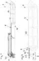
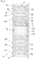
- an energy supply system 1 is shown, which is connected to a housing 20, which houses the cable storage 3, to an internal boom 36 of a hoist not shown in detail here (see Figure 12a to 12d ).
- the carrier 6, which can be wound up or down in or out of the cable storage 3, is fastened by a first end 30 to an external boom 40 which is movable relative to the cable storage 3.
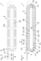
- FIG 2 In isolation, an embodiment of an energy supply system 1 is shown with a line storage 3 arranged in a housing 20, from whose opening 7 a part of the carrier 6 is taken.
- the carrier 6 is formed in this embodiment by a chain 22 with chain links 23, on which guide means 8 in the form of two axially protruding projections 24 per chain link 23 are arranged.
- the line storage 3 has an elongated, almost rectangular shape in this embodiment.
- This embodiment of the carrier 6 is also in the embodiment of the energy storage 1 of the Figures 11a and 11b shown.
- FIG 3 a further embodiment of an energy supply system 1 is shown in isolation, wherein the energy supply system 1 again has a line storage device 3 arranged in a housing 20, from whose opening 7 a part of the carrier 6 is taken.
- the carrier 6 is formed by a chain 22 with chain links 23, on which guide means 8 in the form of an axially protruding projection 24 is arranged for each chain link 23.
- the carrier plate 26 of the line storage device 3 has been made visible in this illustration by partially masking out the cover of the housing 20.
- FIG 4 is a view of the Figure 3 shown in which the cover of the housing 20 has been completely hidden.
- the carrier 6 is designed for at least one energy-carrying line (not visible here, see Figures 5a-5j and Figure 6 ) for the entry and exit of the carrier 6 through the opening 7 of the line storage 3 for section-wise guidance of the carrier 6 and the energy line in the line storage 3 with guide means 8 via a first guide section 9 through a first guide curve 10 and via a second guide section 11 adjoining the first guide curve 10 through a second guide curve 12 and via a second guide curve 12 adjoining the second guide curve 12 and in comparison to the first guide section 9 relative to the winding center 5 (see also Figure 5a ) further inside the third guide section 13 - and analogously via further guide bends 15, 17 and guide sections 14, 16, 18 - to the winding center 5 of the line storage 3.
- the further course of the carrier 6 between the end of the innermost guide section 18 and the winding center 5 is in Figure 4 shown with dashed lines and is the Figure 5a in
- the third guide section 13 is arranged further inward relative to the winding center 5 compared to the first guide section 9.
- the first guide section 9 and the third guide section 13 are arranged opposite one another relative to the winding center 5, with the third guide section 13 being located closer to the winding center 5.
- a third guide arc 14 is shown, which adjoins the third guide section 13 and is located further inward relative to the winding center 5 compared to the first guide arc 10, and to which a fourth guide section 15 is connected, which is located further inward relative to the winding center 5 compared to the second guide section 11.
- the guide sections 9, 11, 13, 15, 17, 19 and guide curves 10, 12, 14, 16, 18 form a guide track 27, wherein the guide track 27 has a substantially spiral-shaped winding course from the opening 7 to the winding center 5, narrowing in the direction of the winding center 5.
- the guide arches 10, 12, 14, 16, 18 are each essentially semicircular in the embodiment shown.
- Groups of guide curves 10, 14, 18 and 12, 16 with different radii of curvature, which have a decreasing radius of curvature from the opening 7 of the line storage 3 to the winding center 5, are arranged concentrically in the embodiment shown.
- the grouping of the guide curves 10, 14, 18 and 12, 16 takes place on opposite sides relative to the winding center 5.
- the guide sections 9, 11, 13, 15, 17, 19 have a substantially straight course and substantially the same longitudinal extension.
- the line storage 3 essentially has an elongated shape with a larger longitudinal extension than transverse extension, wherein the guide sections 9, 11, 13, 15, 17, 19 run essentially along the longitudinal extension of the line storage 3.
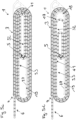
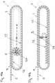
- FIG 5a a substantially completely wound cable storage device 3 is shown.
- the guided part of the section 33 of the carrier 6 with guide means 8 extends substantially over the entire length of the guide track 27 formed by the guide sections 9, 11, 13, 15, 17, 19 and guide bends 10, 12, 14, 16, 18.
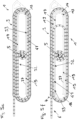
- FIG 5j a substantially completely twisted line storage device 3 is shown.
- the guided part of the section 33 extends essentially over the minimum length of the guide section 9 adjoining the opening 7.
- the unguided section 32 is - due to the rotationally fixed passage 37 - in the Essentially completely wound around the winding center 5.
- the guide track 27 is designed as a single continuous groove in the carrier plate 26 of the cable storage 3.
- the guide sections 9, 11, 13, 15, 17, 19 and guide arches 10, 12, 14, 16, 18 are arranged and spaced apart such that the carrier 6 wound thereon does not touch itself between adjacent guide sections 9, 11, 13, 15, 17, 19 and guide arches 10, 12, 14, 16, 18.
- the carrier 6 has a section 32 with guide means 8 and a section 33 without guide means.
- the section 33 without guide means extends from the second end 31 of the carrier 6 to the beginning of the section 32 with Guide means 8, on which the first guide means 41 of the guided part of the section 32 with guide means 8 is arranged.
- the carrier 6 is connected to the winding center 5 at the second end 31 of the carrier 6.
- the section 33 without guide means runs unguided in the line storage 3, i.e. it is not guided by the guide sections 9, 11, 13, 15, 17, 19 and guide bends 10, 12, 14, 16, 18.
- the carrier 6 in the line storage 3 has a guided section 33 with guide means 8 and an unguided section 32 without guide means.
- the guided part of the section 33 extends essentially from the opening 7 of the line storage 3 via the guide sections 9, 11, 13, 15, 17, 19 and guide bends 10, 12, 14, 16, 18 to the end of the section 33 of the carrier 6 with guide means 8 or to the beginning of the section 32 of the carrier 6 without guide means 8.
- the unguided section 32 extends from there to the winding center 5.
- the unguided section 32 of the carrier 6 can be wound essentially spirally around the winding center 5 and the winding radius of the unguided section 32 of the carrier 6 can increase or decrease when the guided part of the section 33 is wound up and down with guide means 8 of the carrier 6.
- An increase - such as in the transition from Figure 5b to 5a - or reduction - such as in the transition from Figure 5a to 5b - the winding radius of the unguided section 32 can be present in a transition to a loose (upwind) or tight (downwind) winding.
- At least one power line 4 leads into the line storage 3 in the winding center 5 through a rotationally fixed passage 37.
- the carrier 6 runs tangentially in the direction of the guide sections 9, 11, 13, 15, 17, 19 to the rotationally fixed passage 37.
- the twisting of the unguided section 32 which results when the guided part of the section 33 is wound up and down with guide means 8 of the carrier 6, with a second end 31 held rotationally fixed in the winding center 5, for which in the non-inventive embodiment of the Figure 8 a rotary feedthrough 34 is provided, can be permitted by a substantially spiral winding of the section 32 around the winding center 5 and an increasing or decreasing winding radius.
- the space in the line storage 3 taken up or freed up by the winding up or down of the unguided section 32 can be made available or filled by the guided part of the carrier 6 coming out or entering the line storage 3 (see in particular Figures 5a and 5y ).
- the unguided section 32 of the carrier 6 When the unguided section 32 of the carrier 6 is wound around the winding center 5, the unguided section 32 is supported on the section 33 of the carrier 6 guided on the guide sections 9, 11, 13, 15, 17, 19 and guide curves 10, 12, 14, 16, 18 and slides along it. This is particularly the case when the winding radius of the unguided section 32 increases (transition to a loose winding) when the section 33 is wound up.
- the guide sections 9, 11, 13, 15, 17, 19 and guide bends 10, 12, 14, 16, 18 and the corresponding guide means 8 allow the carrier 6 to be guided in sections in the cable storage 3 in a shear-resistant manner. If a tensile or shear force is exerted on the carrier 3 in the direction of the carrier 6, the latter can be moved along the guide sections 9, 11, 13, 15, 17, 19 and guide bends 10, 12, 14, 16, 18.
- the guide sections 9, 11, 13, 15, 17, 19 and guide arches 10, 12, 14, 16, 18 and the corresponding guide means 8 engage with each other in such a way that only a movement of the carrier 6 along the guide sections 9, 11, 13, 15, 17, 19 and guide arches 10, 12, 14, 16, 18 is possible. Buckling and thus disorderly winding up and down of the carrier 6 can be prevented in this way.
- Figure 6 is a cross section through the energy storage device 1 according to the design of the Figure 5a shown.
- the carrier 6 has in section 33 with guide means 8 protruding from the carrier 6, axial projections with rollers 25 mounted thereon, which Guide sections 9, 11, 13, 15, 17, 19 and guide arches (not visible here) engage in the carrier plate 6.
- the unguided section 32 without guide means is not guided by the guide sections and guide arches.
- the carrier 6 is wound up and down essentially in a plane parallel to the carrier plate 6. It can also be seen that the carrier 6 has an essentially constant transverse extension.
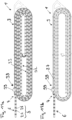
- FIG 7a A design of the carrier 6 is shown schematically, in which the carrier 6 has projections 24 projecting axially therefrom, which engage in a groove-shaped guide track 27 of the carrier plate 26 of the line storage 3. Energy lines 4 are arranged inside the carrier 6. This design essentially corresponds to that of the Figures 5 and 6 .
- Figure 7b is shown schematically an embodiment of the carrier 6, in which the carrier 6 is designed in the form of a casing 21 of the energy line 4.
- a guidance of the carrier 6 is analogous to the embodiment of the Figure 7b with axially projecting projections 24 and a guide track 27.
- Figure 7c schematically shows an embodiment of the carrier 6, in which the guide means of the carrier 6 is designed as a guide track 28, here in the form of a groove, in at least a part of the carrier 6 and the guide curves and guide sections are designed in the form of an arrangement of projections 29 protruding from the carrier plate 6.
- the guide track 28 can be designed in the form of guide tracks arranged in a row in individual chain links.
- the arrangement of projections 29 protruding from the carrier plate 6 can be adapted to the course of the guide track 27 formed by the guide sections 9, 11, 13, 15, 17, 19 and guide curves 10, 12, 14, 16, 18 of the design of the Figures 5 and 6
- a schematic representation of the Figure 7b An analogous design of the carrier 6 in the form of a sheath 21 of the energy line 4 is also conceivable.
- FIG 8 is a device for executing the Figure 5 analogous design of the energy storage 1 is shown, whereby in contrast to the design of the Figure 5 A rotary union 34 is provided in the winding center 5.
- the rotary union 34 is designed as Figure 5
- the twisting of the unguided section 32 described above, which occurs when the guided section 33 of the carrier 6 is wound up and down, can be permitted or prevented here by connecting the second end 31 of the carrier 6 to the rotary union 34. Since there is no spiral winding of the unguided section 32 around the winding center 5 when the carrier 6 is removed from the line storage 3, the unguided section 32 can be made shorter in its longitudinal extension. The transverse extension of the line storage 3 can also be smaller.
- Figure 9 is a device for executing the Figure 5 analogous design of the energy storage device 1 is shown, whereby here also a rotationally fixed passage 37 is provided in the winding center 5, but in contrast to the design of the Figure 5 the unguided section 32 of the carrier 6 when and unwinding of the guided section 33 of the carrier 6 in opposite positions can be wound up and down around the winding center 5.
- the unguided section 32 can be wound essentially spirally around the winding center 5.
- FIG 10a an embodiment of an energy storage device 1 is shown in which the position of the winding center 5 in the line storage device 3 is adjustable.
- the adjustment range is shown by a broken line.
- the winding center 5 is in Figure 10a arranged in the line storage 3 so as to be linearly movable in the direction of the guide sections 9, 11, 13, 15, 17, 19.
- FIG 10b an embodiment of an energy storage device 1 is shown in which the position of the winding center 5 in the line storage device 3 is adjustable.
- the adjustment range is again shown by a broken line.
- the winding center 5 is in Figure 10b arranged in the line storage 3 so as to be linearly movable transversely to the guide sections 9, 11, 13, 15, 17, 19.
- the length of the unguided section 33 of the carrier 6 can be reduced.
- a drive 38 acting on the carrier 6 for winding up and down the at least one carrier 6 is shown.
- the drive 38 has a gear 39 which is inserted into the guide means 8 in the form of the projections 24 of the section 33 of the carrier guided in the line storage 3. 6 engages.
- the drive 38 acting on the carrier 6 with the gear 39 is arranged in this embodiment adjacent to the opening 7 at the beginning of the guide track 27. An arrangement at another point on the guide track is also conceivable.
- the energy supply system 1 is attached to the housing 20 on an internal boom 36, for example an arm of a telescopic arm system, of the hoist 2.
- a working device (not shown here) supplied by the energy supply system 1 can be arranged on the external boom 40 that can be moved for this purpose, for example at the end of a telescopic boom of a telescopic arm system.
- the carrier 6 can be connected to the working device or the external boom 40 with its first end 30.
- the energy supply system 1 can allow a relative movement of the boom 40 and thus of the working device to the line storage 3.
- the working device can remain connected to the carrier 6 and the energy line 4 during the movement and the length of the section of the carrier 6 and the energy line 4 removed from the line storage 3 can be adapted to the relative movement between the working device and the line storage 3.
Landscapes
- Engineering & Computer Science (AREA)
- Mechanical Engineering (AREA)
- General Engineering & Computer Science (AREA)
- Storing, Repeated Paying-Out, And Re-Storing Of Elongated Articles (AREA)
- Control And Safety Of Cranes (AREA)
- Other Liquid Machine Or Engine Such As Wave Power Use (AREA)
Claims (15)
- Système d'alimentation en énergie (1), en particulier pour un outillage fixé ou pouvant être fixé à un mécanisme de levage (2), avec une réserve de câble (3) pour l'enroulement et le déroulement au moins d'un câble d'énergie (4) autour d'un centre d'enroulement (5) de la réserve de câble (3), dans lequel au moins un support (6) est prévu pour l'au moins un câble d'énergie (4) et la réserve de câble (3) présente une ouverture (7) pour l'entrée et la sortie du support (6) et du câble d'énergie (4), dans lequel l'au moins un support (6) peut être guidé à travers l'ouverture (7) pour le guidage par sections du support (6) et du câble d'énergie (4) dans la réserve de câble (3) avec des moyens de guidage (8) sur un premier trajet de guidage (9) par un premier arc de guidage (10) et sur un deuxième trajet de guidage (11) contigu au premier arc de guidage (10) par un deuxième arc de guidage (12) et sur un troisième trajet de guidage (13) se trouvant plus vers l'intérieur par rapport au premier trajet de guidage (9) par rapport au centre d'enroulement (5) et contigu au deuxième arc de guidage (12) - et éventuellement d'autres arcs de guidage et trajets de guidage - vers le centre d'enroulement (5) de la réserve de câble (3), dans lequel le support (6) présente une première extrémité (30) extérieure et une deuxième extrémité (31) intérieure et le support (6) présente une section (32) avec des moyens de guidage (8) et une section (33) sans moyen de guidage, dans lequel la section (33) s'étend sans moyen de guidage de la deuxième extrémité (31) à la section (32) avec des moyens de guidage et le support (6) est relié à la deuxième extrémité (31) du support (6) au centre d'enroulement (5) et la section (33) n'est pas guidée sans moyen de guidage dans la réserve de câble (3), dans lequel la section (33) non guidée du support (6) est enroulable sensiblement en spirale autour du centre d'enroulement (5), caractérisé en ce que le rayon d'enroulement de la section non guidée (33) du support (6) augmente ou se réduit lors de l'enroulement et du déroulement de la partie guidée de la section (33) du support (6), dans lequel le câble d'énergie (4) débouche dans le centre d'enroulement (5) par un passage solidaire en rotation dans la réserve de câble (3).
- Système d'alimentation en énergie selon la revendication 1, dans lequel le support est réalisé sous la forme d'au moins une enveloppe (21) du câble d'énergie (4) ou sous la forme d'au moins une chaîne (22) avec des maillons de chaîne (23) reliés par articulation entre eux.
- Système d'alimentation en énergie selon l'une quelconque des revendications précédentes, dans lequel- les moyens de guidage (8) du support (6) sont réalisés comme saillies (24) axiales dépassant d'au moins une partie du support (6), de préférence avec des rouleaux (25) agencés sur celles-ci, et la réserve de câble (3) présente au moins une plaque de support (26) plane et les arcs de guidage et trajets de guidage sont réalisés sous la forme d'une bande de guidage (27), de préférence sous la forme d'une rainure, dans la plaque de support (26), ou- les moyens de guidage (8) du support (6) sont réalisés comme bande de guidage (28) sous la forme de bandes de guidage, de préférence sous la forme de rainures, dans au moins une partie du support (6) et les arcs de guidage et trajets de guidage sont réalisés sous la forme d'un agencement de saillies (29) dépassant de la plaque de support, de préférence avec des rouleaux agencés sur celles-ci.
- Système d'alimentation en énergie selon l'une quelconque des revendications précédentes, dans lequel la section (33) non guidée du support (6) peut être enroulée et déroulée lors de l'enroulement et du déroulement de la partie guidée de la section (32) du support (6) dans des positions opposées autour du centre d'enroulement (5).
- Système d'alimentation en énergie selon l'une quelconque des revendications précédentes, dans lequel la distance des arcs de guidage (10, 12, 14, 16, 18) les uns par rapport aux autres est sensiblement invariable.
- Système d'alimentation en énergie selon l'une quelconque des revendications précédentes, dans lequel- les arcs de guidage (10, 12, 14, 16, 18) présentent sensiblement un angle d'enroulement de 180 degrés et/ou- les arcs de guidage (10, 12, 14, 16, 18) présentent des rayons de courbure différents et/ou identiques, dans lequel les arcs de guidage (10, 12, 14, 16, 18) avec différents rayons de courbure de l'ouverture (7) de la réserve de câble (3) au centre d'enroulement (5) présentent un rayon de courbure décroissant, et/ou- le rayon de courbure respectif d'un arc de guidage (10, 12, 14, 16, 18) est constant.
- Système d'alimentation en énergie selon l'une quelconque des revendications précédentes, dans lequel les trajets de guidage (9, 11, 13, 15, 17, 19) respectifs présentent une étendue sensiblement en ligne droite et/ou sensiblement la même étendue longitudinale.
- Système d'alimentation en énergie selon l'une quelconque des revendications précédentes, dans lequel la réserve de câble (3) présente sensiblement une forme oblongue avec une étendue longitudinale supérieure à l'étendue transversale et les trajets de guidage (9, 11, 13, 15, 17, 19) s'étendent sensiblement le long de l'étendue longitudinale de la réserve de câble (3).
- Système d'alimentation en énergie selon l'une quelconque des revendications précédentes, dans lequel l'enroulement et le déroulement d'au moins un support (6) sont effectués sensiblement dans un plan.
- Système d'alimentation en énergie selon l'une quelconque des revendications précédentes, dans lequel l'entrée et la sortie d'au moins un support (6) par l'ouverture (7) sont effectuées dans une position fixe de la réserve de câble (3).
- Système d'alimentation en énergie selon l'une quelconque des revendications précédentes, dans lequel l'au moins un support (6) présente une étendue transversale sensiblement constante.
- Système d'alimentation en énergie selon l'une quelconque des revendications précédentes, dans lequel les arcs de guidage (10, 12, 14, 16, 18) et trajets de guidage (9, 11, 13, 15, 17, 19) présentent de l'ouverture (7) vers le centre d'enroulement (5) une étendue sensiblement en spirale et l'au moins un support (6) peut être enroulé et déroulé par sections sensiblement en spirale dans la réserve de câble (3) vers le centre d'enroulement (5).
- Système d'alimentation en énergie selon l'une quelconque des revendications précédentes, dans lequel la position du centre d'enroulement (5) est réalisée de manière réglable dans la réserve de câble (3), dans lequel de préférence le centre d'enroulement (5) est agencé dans la réserve de câble (3) de manière déplaçable linéairement, en particulier de préférence linéairement en direction et/ou transversalement aux trajets de guidage (9, 11, 13, 15, 17, 19) .
- Mécanisme de levage (35), en particulier grue, avec un système d'alimentation en énergie (1) selon l'une quelconque des revendications précédentes.
- Mécanisme de levage (35) selon la revendication précédente, dans lequel le système d'alimentation en énergie (1) est fixé à une flèche (36) du mécanisme de levage (35).
Applications Claiming Priority (2)
| Application Number | Priority Date | Filing Date | Title |
|---|---|---|---|
| ATGM50231/2019U AT17144U1 (de) | 2019-12-17 | 2019-12-17 | Energiezuführsystem |
| PCT/AT2020/060445 WO2021119686A1 (fr) | 2019-12-17 | 2020-12-10 | Système d'alimentation en énergie |
Publications (3)
| Publication Number | Publication Date |
|---|---|
| EP4077184A1 EP4077184A1 (fr) | 2022-10-26 |
| EP4077184C0 EP4077184C0 (fr) | 2024-05-01 |
| EP4077184B1 true EP4077184B1 (fr) | 2024-05-01 |
Family
ID=76476462
Family Applications (1)
| Application Number | Title | Priority Date | Filing Date |
|---|---|---|---|
| EP20825139.7A Active EP4077184B1 (fr) | 2019-12-17 | 2020-12-10 | Système d'alimentation en énergie |
Country Status (8)
| Country | Link |
|---|---|
| US (1) | US12466701B2 (fr) |
| EP (1) | EP4077184B1 (fr) |
| JP (1) | JP7642644B2 (fr) |
| KR (1) | KR102783940B1 (fr) |
| CN (1) | CN115052827B (fr) |
| AT (1) | AT17144U1 (fr) |
| ES (1) | ES2985577T3 (fr) |
| WO (1) | WO2021119686A1 (fr) |
Families Citing this family (2)
| Publication number | Priority date | Publication date | Assignee | Title |
|---|---|---|---|---|
| BE1030526B1 (nl) * | 2022-05-16 | 2023-12-11 | Werkhuizen Jacobs | Rolkraan voor een transportvoertuig met een standaard autolaadkraan met een derde punt en werkwijze voor de bouw van zulke rolkraan |
| KR102778648B1 (ko) * | 2024-10-29 | 2025-03-11 | (주)씨앤지마이크로웨이브 | 케이블 권취 및 권출 시스템을 포함하는 구조체 회전 장치 |
Family Cites Families (15)
| Publication number | Priority date | Publication date | Assignee | Title |
|---|---|---|---|---|
| AT13742B (fr) | 1902-03-24 | 1903-10-26 | Alois Suchy | |
| IT1069197B (it) * | 1976-03-10 | 1985-03-25 | Lamperti Enrico | Aspo devolgitore ad azionamento elettrico con carrello retratti le nel basamento e colonna por tante |
| AU8247382A (en) * | 1981-04-14 | 1983-04-21 | Coles Cranes Ltd. | Telescopic booms for cranes |
| FR2586634B1 (fr) * | 1985-08-27 | 1987-12-11 | Peugeot Aciers Et Outillage | Dispositif de stockage pour ruban d'entrainement notamment de ceinture de securite passive de vehicule automobile |
| DE4108534A1 (de) * | 1991-03-15 | 1992-09-17 | Gore W L & Ass Gmbh | Wickelvorrichtung zum auf- und abwickeln einer leitung |
| DE19613700A1 (de) * | 1996-03-29 | 1997-10-02 | M E P Gmbh Ges Fuer Consulting | Teleskopartig auseinanderfahrbarer Maschinenteil |
| ITMI20040405U1 (it) * | 2004-09-02 | 2004-12-02 | Kabelschlepp Italia S R L | Disposizione migliorata di catena portachiavi in posizione verticale ascendente inserita in gruppi telescopici a due o piu' sezioni |
| EP2610208A1 (fr) * | 2011-12-27 | 2013-07-03 | Palfinger AG | Système d'apport énergétique |
| US9791071B2 (en) * | 2013-03-07 | 2017-10-17 | Oshkosh Corporation | Internally supported power track |
| AT13742U1 (de) * | 2013-06-28 | 2014-08-15 | Palfinger Ag | Energiezuführsystem |
| JP6421109B2 (ja) * | 2015-11-16 | 2018-11-07 | 株式会社椿本チエイン | ケーブル類保護案内装置及びガイドレール |
| DE202016102087U1 (de) | 2016-04-20 | 2017-05-26 | Igus Gmbh | Leitungsführungssystem für mindestens eine auf- und abspulbare Versorgungsleitung sowie Drehführung hierfür |
| DE202016105840U1 (de) * | 2016-10-18 | 2017-11-23 | Igus Gmbh | Schnelllauf-Hubvorrichtung mit Versorgungsleitung und Energieführungskette hierfür |
| DE202019107118U1 (de) * | 2019-12-19 | 2021-03-22 | Igus Gmbh | Leitungsführung und Speichereinheit für eine Leitungsführung |
| DE202019107117U1 (de) * | 2019-12-19 | 2021-04-19 | Igus Gmbh | Energieführungskette und Speichereinheit für eine Energieführungskette |
-
2019
- 2019-12-17 AT ATGM50231/2019U patent/AT17144U1/de unknown
-
2020
- 2020-12-10 ES ES20825139T patent/ES2985577T3/es active Active
- 2020-12-10 WO PCT/AT2020/060445 patent/WO2021119686A1/fr not_active Ceased
- 2020-12-10 EP EP20825139.7A patent/EP4077184B1/fr active Active
- 2020-12-10 JP JP2022537044A patent/JP7642644B2/ja active Active
- 2020-12-10 CN CN202080095736.5A patent/CN115052827B/zh active Active
- 2020-12-10 KR KR1020227022491A patent/KR102783940B1/ko active Active
-
2022
- 2022-06-16 US US17/842,028 patent/US12466701B2/en active Active
Also Published As
| Publication number | Publication date |
|---|---|
| EP4077184C0 (fr) | 2024-05-01 |
| KR102783940B1 (ko) | 2025-03-18 |
| US20220306430A1 (en) | 2022-09-29 |
| CN115052827A (zh) | 2022-09-13 |
| US12466701B2 (en) | 2025-11-11 |
| JP2023506906A (ja) | 2023-02-20 |
| CN115052827B (zh) | 2025-09-23 |
| ES2985577T3 (es) | 2024-11-06 |
| WO2021119686A1 (fr) | 2021-06-24 |
| EP4077184A1 (fr) | 2022-10-26 |
| KR20220104254A (ko) | 2022-07-26 |
| JP7642644B2 (ja) | 2025-03-10 |
| AT17144U1 (de) | 2021-07-15 |
Similar Documents
| Publication | Publication Date | Title |
|---|---|---|
| EP3445695B1 (fr) | Système de guidage de ligne pour au moins une ligne d'alimentation pouvant être bobinée et dévidée ainsi que guidage rotatif associé | |
| EP3424871B1 (fr) | Dispositif de treuil à câble | |
| DE102016204832B3 (de) | Führungseinrichtung und Röntgeneinrichtung | |
| EP4077184B1 (fr) | Système d'alimentation en énergie | |
| EP4077972B1 (fr) | Chaîne porte-câbles et unité d'accumulation pour une chaîne porte-câbles | |
| DE102014107924A1 (de) | Zahnradanordnung | |
| DE2632684A1 (de) | Foerdersystem mit seil | |
| EP3013726B1 (fr) | Système d'alimentation en énergie | |
| EP3455441B1 (fr) | Dispositif d'entraînement | |
| EP2720970B1 (fr) | Dispositif pour dérouler et enrouler une ou plusieurs lignes | |
| EP4031790B1 (fr) | Guidage rotatif pour une ou plusieurs lignes | |
| EP4107096B1 (fr) | Dispositif et procédé pour le transport de conteneurs | |
| WO2022233853A1 (fr) | Chaîne d'énergie comprenant une unité d'entraînement, et système constitué d'une chaîne d'énergie comprenant une unité d'entraînement et une unité de stockage | |
| DE4028816A1 (de) | Kabelrolle fuer eine aus- und einfahrbare lenksaeule in fahrzeugen | |
| DE10141366A1 (de) | Vorrichtung zum Führen und/oder Spannen eines Leitungsbündels bei einem Roboter | |
| EP1602458B1 (fr) | Poignet de robot avec guidage de tuyau pour un robot de peinture | |
| WO2008046811A1 (fr) | Système de guidage d'énergie pour de longues voies de déplacement | |
| WO2019201680A1 (fr) | Chaîne de transport d'énergie comprenant une pièce transversale, une languette latérale correspondante et ensemble de guidage comportant celle-ci | |
| EP3645913A1 (fr) | Système muni de deux chaînes porte-câbles et d'un point de fixation déplaçable | |
| DE20113950U1 (de) | Vorrichtung zum Führen und/oder Spannen eines Leitungsbündels bei einem Roboter | |
| WO2018065377A1 (fr) | Passage tournant pour lignes ou conduits | |
| DE1945295A1 (de) | Vorrichtung zur Energiezuleitung zu auf kreisfoermigen Bahnen beweglichen Verbrauchern | |
| DE2166639A1 (de) | Draht-vorschubgetriebe, insbesondere fuer elektrodendraht von lichtbogenschweissmaschinen | |
| AT521489A4 (de) | Werkzeug-Transfervorrichtung | |
| WO2025088140A1 (fr) | Module rotatif pour guider au moins une ligne et module rotatif comprenant au moins une ligne |
Legal Events
| Date | Code | Title | Description |
|---|---|---|---|
| STAA | Information on the status of an ep patent application or granted ep patent |
Free format text: STATUS: UNKNOWN |
|
| STAA | Information on the status of an ep patent application or granted ep patent |
Free format text: STATUS: THE INTERNATIONAL PUBLICATION HAS BEEN MADE |
|
| PUAI | Public reference made under article 153(3) epc to a published international application that has entered the european phase |
Free format text: ORIGINAL CODE: 0009012 |
|
| STAA | Information on the status of an ep patent application or granted ep patent |
Free format text: STATUS: REQUEST FOR EXAMINATION WAS MADE |
|
| 17P | Request for examination filed |
Effective date: 20220718 |
|
| AK | Designated contracting states |
Kind code of ref document: A1 Designated state(s): AL AT BE BG CH CY CZ DE DK EE ES FI FR GB GR HR HU IE IS IT LI LT LU LV MC MK MT NL NO PL PT RO RS SE SI SK SM TR |
|
| DAV | Request for validation of the european patent (deleted) | ||
| DAX | Request for extension of the european patent (deleted) | ||
| P01 | Opt-out of the competence of the unified patent court (upc) registered |
Effective date: 20230530 |
|
| GRAP | Despatch of communication of intention to grant a patent |
Free format text: ORIGINAL CODE: EPIDOSNIGR1 |
|
| STAA | Information on the status of an ep patent application or granted ep patent |
Free format text: STATUS: GRANT OF PATENT IS INTENDED |
|
| RIC1 | Information provided on ipc code assigned before grant |
Ipc: H02G 11/02 20060101ALI20231107BHEP Ipc: B66C 23/70 20060101ALI20231107BHEP Ipc: B66C 23/00 20060101ALI20231107BHEP Ipc: B66C 13/14 20060101ALI20231107BHEP Ipc: H02G 11/00 20060101ALI20231107BHEP Ipc: B66C 13/12 20060101ALI20231107BHEP Ipc: B65H 75/36 20060101AFI20231107BHEP |
|
| INTG | Intention to grant announced |
Effective date: 20231211 |
|
| GRAS | Grant fee paid |
Free format text: ORIGINAL CODE: EPIDOSNIGR3 |
|
| GRAA | (expected) grant |
Free format text: ORIGINAL CODE: 0009210 |
|
| STAA | Information on the status of an ep patent application or granted ep patent |
Free format text: STATUS: THE PATENT HAS BEEN GRANTED |
|
| AK | Designated contracting states |
Kind code of ref document: B1 Designated state(s): AL AT BE BG CH CY CZ DE DK EE ES FI FR GB GR HR HU IE IS IT LI LT LU LV MC MK MT NL NO PL PT RO RS SE SI SK SM TR |
|
| REG | Reference to a national code |
Ref country code: GB Ref legal event code: FG4D Free format text: NOT ENGLISH |
|
| REG | Reference to a national code |
Ref country code: CH Ref legal event code: EP |
|
| REG | Reference to a national code |
Ref country code: IE Ref legal event code: FG4D Free format text: LANGUAGE OF EP DOCUMENT: GERMAN |
|
| REG | Reference to a national code |
Ref country code: DE Ref legal event code: R096 Ref document number: 502020007903 Country of ref document: DE |
|
| U01 | Request for unitary effect filed |
Effective date: 20240528 |
|
| P04 | Withdrawal of opt-out of the competence of the unified patent court (upc) registered |
Free format text: CASE NUMBER: APP_33185/2024 Effective date: 20240603 |
|
| U07 | Unitary effect registered |
Designated state(s): AT BE BG DE DK EE FI FR IT LT LU LV MT NL PT SE SI Effective date: 20240606 |
|
| PG25 | Lapsed in a contracting state [announced via postgrant information from national office to epo] |
Ref country code: IS Free format text: LAPSE BECAUSE OF FAILURE TO SUBMIT A TRANSLATION OF THE DESCRIPTION OR TO PAY THE FEE WITHIN THE PRESCRIBED TIME-LIMIT Effective date: 20240901 |
|
| PG25 | Lapsed in a contracting state [announced via postgrant information from national office to epo] |
Ref country code: HR Free format text: LAPSE BECAUSE OF FAILURE TO SUBMIT A TRANSLATION OF THE DESCRIPTION OR TO PAY THE FEE WITHIN THE PRESCRIBED TIME-LIMIT Effective date: 20240501 |
|
| PG25 | Lapsed in a contracting state [announced via postgrant information from national office to epo] |
Ref country code: GR Free format text: LAPSE BECAUSE OF FAILURE TO SUBMIT A TRANSLATION OF THE DESCRIPTION OR TO PAY THE FEE WITHIN THE PRESCRIBED TIME-LIMIT Effective date: 20240802 |
|
| PG25 | Lapsed in a contracting state [announced via postgrant information from national office to epo] |
Ref country code: PL Free format text: LAPSE BECAUSE OF FAILURE TO SUBMIT A TRANSLATION OF THE DESCRIPTION OR TO PAY THE FEE WITHIN THE PRESCRIBED TIME-LIMIT Effective date: 20240501 |
|
| PG25 | Lapsed in a contracting state [announced via postgrant information from national office to epo] |
Ref country code: PL Free format text: LAPSE BECAUSE OF FAILURE TO SUBMIT A TRANSLATION OF THE DESCRIPTION OR TO PAY THE FEE WITHIN THE PRESCRIBED TIME-LIMIT Effective date: 20240501 Ref country code: IS Free format text: LAPSE BECAUSE OF FAILURE TO SUBMIT A TRANSLATION OF THE DESCRIPTION OR TO PAY THE FEE WITHIN THE PRESCRIBED TIME-LIMIT Effective date: 20240901 Ref country code: HR Free format text: LAPSE BECAUSE OF FAILURE TO SUBMIT A TRANSLATION OF THE DESCRIPTION OR TO PAY THE FEE WITHIN THE PRESCRIBED TIME-LIMIT Effective date: 20240501 Ref country code: GR Free format text: LAPSE BECAUSE OF FAILURE TO SUBMIT A TRANSLATION OF THE DESCRIPTION OR TO PAY THE FEE WITHIN THE PRESCRIBED TIME-LIMIT Effective date: 20240802 Ref country code: RS Free format text: LAPSE BECAUSE OF FAILURE TO SUBMIT A TRANSLATION OF THE DESCRIPTION OR TO PAY THE FEE WITHIN THE PRESCRIBED TIME-LIMIT Effective date: 20240801 |
|
| REG | Reference to a national code |
Ref country code: ES Ref legal event code: FG2A Ref document number: 2985577 Country of ref document: ES Kind code of ref document: T3 Effective date: 20241106 |
|
| P05 | Withdrawal of opt-out of the competence of the unified patent court (upc) changed |
Free format text: CASE NUMBER: APP_33185/2024 Effective date: 20240606 |
|
| PG25 | Lapsed in a contracting state [announced via postgrant information from national office to epo] |
Ref country code: CZ Free format text: LAPSE BECAUSE OF FAILURE TO SUBMIT A TRANSLATION OF THE DESCRIPTION OR TO PAY THE FEE WITHIN THE PRESCRIBED TIME-LIMIT Effective date: 20240501 |
|
| PG25 | Lapsed in a contracting state [announced via postgrant information from national office to epo] |
Ref country code: SK Free format text: LAPSE BECAUSE OF FAILURE TO SUBMIT A TRANSLATION OF THE DESCRIPTION OR TO PAY THE FEE WITHIN THE PRESCRIBED TIME-LIMIT Effective date: 20240501 Ref country code: RO Free format text: LAPSE BECAUSE OF FAILURE TO SUBMIT A TRANSLATION OF THE DESCRIPTION OR TO PAY THE FEE WITHIN THE PRESCRIBED TIME-LIMIT Effective date: 20240501 |
|
| PG25 | Lapsed in a contracting state [announced via postgrant information from national office to epo] |
Ref country code: SM Free format text: LAPSE BECAUSE OF FAILURE TO SUBMIT A TRANSLATION OF THE DESCRIPTION OR TO PAY THE FEE WITHIN THE PRESCRIBED TIME-LIMIT Effective date: 20240501 |
|
| U20 | Renewal fee for the european patent with unitary effect paid |
Year of fee payment: 5 Effective date: 20241223 |
|
| PG25 | Lapsed in a contracting state [announced via postgrant information from national office to epo] |
Ref country code: SM Free format text: LAPSE BECAUSE OF FAILURE TO SUBMIT A TRANSLATION OF THE DESCRIPTION OR TO PAY THE FEE WITHIN THE PRESCRIBED TIME-LIMIT Effective date: 20240501 Ref country code: SK Free format text: LAPSE BECAUSE OF FAILURE TO SUBMIT A TRANSLATION OF THE DESCRIPTION OR TO PAY THE FEE WITHIN THE PRESCRIBED TIME-LIMIT Effective date: 20240501 Ref country code: RO Free format text: LAPSE BECAUSE OF FAILURE TO SUBMIT A TRANSLATION OF THE DESCRIPTION OR TO PAY THE FEE WITHIN THE PRESCRIBED TIME-LIMIT Effective date: 20240501 Ref country code: CZ Free format text: LAPSE BECAUSE OF FAILURE TO SUBMIT A TRANSLATION OF THE DESCRIPTION OR TO PAY THE FEE WITHIN THE PRESCRIBED TIME-LIMIT Effective date: 20240501 |
|
| REG | Reference to a national code |
Ref country code: DE Ref legal event code: R097 Ref document number: 502020007903 Country of ref document: DE |
|
| PLBE | No opposition filed within time limit |
Free format text: ORIGINAL CODE: 0009261 |
|
| STAA | Information on the status of an ep patent application or granted ep patent |
Free format text: STATUS: NO OPPOSITION FILED WITHIN TIME LIMIT |
|
| 26N | No opposition filed |
Effective date: 20250204 |
|
| PG25 | Lapsed in a contracting state [announced via postgrant information from national office to epo] |
Ref country code: MC Free format text: LAPSE BECAUSE OF FAILURE TO SUBMIT A TRANSLATION OF THE DESCRIPTION OR TO PAY THE FEE WITHIN THE PRESCRIBED TIME-LIMIT Effective date: 20240501 |
|
| PG25 | Lapsed in a contracting state [announced via postgrant information from national office to epo] |
Ref country code: IE Free format text: LAPSE BECAUSE OF NON-PAYMENT OF DUE FEES Effective date: 20241210 |
|
| REG | Reference to a national code |
Ref country code: CH Ref legal event code: U11 Free format text: ST27 STATUS EVENT CODE: U-0-0-U10-U11 (AS PROVIDED BY THE NATIONAL OFFICE) Effective date: 20260101 |
|
| PGFP | Annual fee paid to national office [announced via postgrant information from national office to epo] |
Ref country code: GB Payment date: 20251218 Year of fee payment: 6 |
|
| PGFP | Annual fee paid to national office [announced via postgrant information from national office to epo] |
Ref country code: NO Payment date: 20251216 Year of fee payment: 6 |
|
| U20 | Renewal fee for the european patent with unitary effect paid |
Year of fee payment: 6 Effective date: 20251222 |
|
| PGFP | Annual fee paid to national office [announced via postgrant information from national office to epo] |
Ref country code: ES Payment date: 20260119 Year of fee payment: 6 |
|
| PGFP | Annual fee paid to national office [announced via postgrant information from national office to epo] |
Ref country code: CH Payment date: 20260101 Year of fee payment: 6 |