EP4031790B1 - Guidage rotatif pour une ou plusieurs lignes - Google Patents
Guidage rotatif pour une ou plusieurs lignes Download PDFInfo
- Publication number
- EP4031790B1 EP4031790B1 EP20772012.9A EP20772012A EP4031790B1 EP 4031790 B1 EP4031790 B1 EP 4031790B1 EP 20772012 A EP20772012 A EP 20772012A EP 4031790 B1 EP4031790 B1 EP 4031790B1
- Authority
- EP
- European Patent Office
- Prior art keywords
- receiving
- rotary guide
- line
- guide
- rotation
- Prior art date
- Legal status (The legal status is an assumption and is not a legal conclusion. Google has not performed a legal analysis and makes no representation as to the accuracy of the status listed.)
- Active
Links
Images

Classifications
-
- B—PERFORMING OPERATIONS; TRANSPORTING
- B65—CONVEYING; PACKING; STORING; HANDLING THIN OR FILAMENTARY MATERIAL
- B65H—HANDLING THIN OR FILAMENTARY MATERIAL, e.g. SHEETS, WEBS, CABLES
- B65H75/00—Storing webs, tapes, or filamentary material, e.g. on reels
- B65H75/02—Cores, formers, supports, or holders for coiled, wound, or folded material, e.g. reels, spindles, bobbins, cop tubes, cans, mandrels or chucks
- B65H75/34—Cores, formers, supports, or holders for coiled, wound, or folded material, e.g. reels, spindles, bobbins, cop tubes, cans, mandrels or chucks specially adapted or mounted for storing and repeatedly paying-out and re-storing lengths of material provided for particular purposes, e.g. anchored hoses, power cables
- B65H75/38—Cores, formers, supports, or holders for coiled, wound, or folded material, e.g. reels, spindles, bobbins, cop tubes, cans, mandrels or chucks specially adapted or mounted for storing and repeatedly paying-out and re-storing lengths of material provided for particular purposes, e.g. anchored hoses, power cables involving the use of a core or former internal to, and supporting, a stored package of material
- B65H75/44—Constructional details
- B65H75/4449—Arrangements or adaptations to avoid movable contacts or rotary couplings, e.g. by the use of an expansion chamber for a lenght of the cord or hose
- B65H75/4452—Simultaneous winding and unwinding of the material, e.g. winding or unwinding on a stationary drum while respectively unwinding or winding on a rotating drum using a planetary guiding roller
-
- F—MECHANICAL ENGINEERING; LIGHTING; HEATING; WEAPONS; BLASTING
- F16—ENGINEERING ELEMENTS AND UNITS; GENERAL MEASURES FOR PRODUCING AND MAINTAINING EFFECTIVE FUNCTIONING OF MACHINES OR INSTALLATIONS; THERMAL INSULATION IN GENERAL
- F16L—PIPES; JOINTS OR FITTINGS FOR PIPES; SUPPORTS FOR PIPES, CABLES OR PROTECTIVE TUBING; MEANS FOR THERMAL INSULATION IN GENERAL
- F16L3/00—Supports for pipes, cables or protective tubing, e.g. hangers, holders, clamps, cleats, clips, brackets
- F16L3/01—Supports for pipes, cables or protective tubing, e.g. hangers, holders, clamps, cleats, clips, brackets for supporting or guiding the pipes, cables or protective tubing, between relatively movable points, e.g. movable channels
- F16L3/012—Supports for pipes, cables or protective tubing, e.g. hangers, holders, clamps, cleats, clips, brackets for supporting or guiding the pipes, cables or protective tubing, between relatively movable points, e.g. movable channels using reels
-
- H—ELECTRICITY
- H02—GENERATION; CONVERSION OR DISTRIBUTION OF ELECTRIC POWER
- H02G—INSTALLATION OF ELECTRIC CABLES OR LINES, OR OF COMBINED OPTICAL AND ELECTRIC CABLES OR LINES
- H02G11/00—Arrangements of electric cables or lines between relatively-movable parts
- H02G11/02—Arrangements of electric cables or lines between relatively-movable parts using take-up reel or drum
-
- B—PERFORMING OPERATIONS; TRANSPORTING
- B65—CONVEYING; PACKING; STORING; HANDLING THIN OR FILAMENTARY MATERIAL
- B65H—HANDLING THIN OR FILAMENTARY MATERIAL, e.g. SHEETS, WEBS, CABLES
- B65H2701/00—Handled material; Storage means
- B65H2701/30—Handled filamentary material
- B65H2701/33—Hollow or hose-like material
-
- B—PERFORMING OPERATIONS; TRANSPORTING
- B65—CONVEYING; PACKING; STORING; HANDLING THIN OR FILAMENTARY MATERIAL
- B65H—HANDLING THIN OR FILAMENTARY MATERIAL, e.g. SHEETS, WEBS, CABLES
- B65H2701/00—Handled material; Storage means
- B65H2701/30—Handled filamentary material
- B65H2701/34—Handled filamentary material electric cords or electric power cables
Definitions
- the invention generally relates to a rotary guide for at least one line or multiple lines that is/are to be routed between two points that can be rotated relative to one another by a predetermined or limited angle of rotation, in particular between end points of a line section accommodated in the rotary guide.
- Endlessly rotatable rotary guides are known from hydraulics and pneumatics.
- slip rings or sliding contacts for endless rotary transmission are well known for electrical power or signals.
- an interruption in the line is absolutely necessary in order to connect the interfaces to the rotary guide or the slip ring on both sides.
- bushings with sliding contacts are not suitable or undesirable for many applications, such as for lines for data transmission or for lines or line routing devices or energy supply chains, which in turn carry several cables and hoses, since the transmission quality of a data line in particular is affected by interfaces such as Slip rings and the like. Is deteriorated. Also for other applications, e.g. transmission of hydraulic or pneumatic operating media through hoses, interfaces such as e.g. rotary couplings have structural and qualitative disadvantages.
- the invention therefore specifically relates to an uninterrupted but limited rotation angle rotary guide for at least one flexible line or line guide device, ie a rotary guide, which allows a limited angle of rotation without interrupting the line(s).
- Such generic rotary guides typically comprise two receiving parts, e.g. housing parts, rotatably mounted about a common axis of rotation relative to each other, in particular about a predetermined or limited angle of rotation, for receiving one of two about the common axis of rotation in opposite directions, i.e. with an opposite direction of rotation relative to one another partial sections of a line section that can be accommodated in the rotary guide, and a deflection unit for supporting a deflection area.
- the deflection area refers in particular to a variable or movable section of the line in which, as in a turning area, the line to be routed can be folded over between the sections to be wound up in opposite directions, so that the line section that can be accommodated in the rotary guide is rotated by a relative rotation of the receiving parts about the common axis of rotation Recording part can be deflected into the other receiving part.
- Such a generic rotary guide for flexible electrical flat cables or ribbon cables is known from the patent DE 40 04 233 A1 known.
- This rotary guide with a limited angle of rotation has a housing with two housing parts that can be rotated relative to one another about an axis of rotation.
- the housing defines a receiving space that is essentially cylindrical in relation to the axis of rotation for an uninterrupted run of the flat cable with two cable sections wound helically around the axis of rotation, i.e. screw-like or corkscrew-like, each with several windings and a deflection area or U-shaped turning area connecting these cable sections.
- This is curved around the axis of rotation and around a deflection axis perpendicular thereto, essentially in a U-shape, so that, depending on the angle of rotation, one cable section laid down helically is lengthened and the other cable section laid down helically is shortened.
- Another rotary guide for uninterrupted management of at least one line is from DE 20 2016 105 507 U1 known.
- This rotary guide comprises two housing parts, which can be rotated relative to one another about an axis of rotation, for receiving one of two line sections curved in opposite directions about the axis of rotation.
- the housing parts are designed essentially as hollow cylinders or pot-like, with the radius of the outer housing wall specifying the curvature of the line section accommodated.
- the turning guide after the DE 20 2016 105 507 U1 has a simplified structure and also allows several lines to be routed, for example in a corrugated hose and the like, but only over a relatively limited angle of rotation of typically 360° and a maximum of 540°.
- the line or line guiding device is wound helically in a plurality of first spiral layers and a plurality of second spiral layers, in the opposite direction to the direction of rotation of the first spiral layers around a rotary shaft.
- This rotary guide has a considerable axial length in order to be able to accommodate several windings of the cable and to achieve greater angles of rotation.
- the windings of the line are supported on a rotationally decoupled cylindrical sleeve that extends in the axial direction.
- a first object of the present invention is therefore to propose a generic, uninterrupted, rotational angle-limited rotary guide that allows rotational angles greater than 540°, in particular greater than 1000°, and in which the axial dimension is kept as small as possible.
- the friction between different line sections should also be as low as possible.
- a further independent task consists in proposing a simplified structure which, in particular, enables subsequent, simple insertion of different, application-dependent lines by the end user himself.
- each of the two receiving parts has a spiral-shaped receiving groove with a plurality of turns running around the common axis of rotation and from an initial radius to an end radius for at least partially receiving a line section in the receiving groove, wherein the Windings, preferably all windings, of the receiving groove of both receiving parts each run in a plane predetermined by the respective receiving part perpendicular to the common axis of rotation.
- the spatial shape of the receiving grooves can correspond in particular to a flat spiral.
- the deflection unit has at least one active surface that extends or is radially adjustable between the starting radius and the end radius with respect to the common axis of rotation, which cooperates with the receiving grooves of the receiving parts to move the line section of the line(s) to be routed when the receiving parts rotate relative to the common axis of rotation from the receiving groove of one receiving part into the receiving groove of the other receiving part.
- a line section to be held in the rotary guide of a line or line guide device to be guided can be in the axial Direction or in the direction of the depth of the receiving groove can be completely or only partially received in the receiving groove.
- a depth of the receiving groove or the dimension of the receiving groove in the axial direction can be smaller than the diameter of the line or line guiding device within the line section, so that—seen in a sectional plane parallel to the axis of rotation—the line section under consideration partially protrudes from the receiving groove can.
- Preference is given to receiving the line(s) completely in the receiving grooves.
- the depth of the receiving groove is preferably the same in all turns.
- the spiral shape of the receiving groove is therefore not helical, helical or corkscrew-like. Rather, a groove is proposed which runs in a plane perpendicular to the axis of rotation of the rotary guide, in particular exclusively in the form of a flat spiral.
- the windings of the spiral-shaped receiving groove according to the invention thus run around the axis of rotation in a plane from a smallest initial radius, the radius of the spiral at the starting point of the receiving groove, to a maximum final radius, the radius of the spiral at the end point of the receiving groove, where - e.g. viewed in polar coordinates -
- the radius r of the windings increases with the angular measure of the polar angle, in particular constantly growing.
- All turns of the receiving groove preferably intersect a plane that runs perpendicular to the axis of rotation.
- the active surface according to the invention can extend in the radial direction with respect to the axis of rotation of the rotary guide.
- it can be formed at least in part by an arcuate surface on the deflection unit, the axis of curvature of which runs in the radial direction.
- the active surface can include several separate sections that do not necessarily have to form a contiguous surface in the geometric sense.
- the active surface can also be radial be adjustable or movable.
- the active surface can be formed, for example, by the surface of a roller that can be rotated about a roller axis that runs radially to the axis of rotation of the rotary guide, wherein the roller can be mounted so that it can be adjusted in the radial direction along this roller axis.
- the surface of the roller can also form a coherent active surface, for example corresponding to an inner half of a torus surface.
- An advantage of the solution according to the invention is that the rotary guide can be designed to be particularly flat, with a particularly small overall axial dimension and yet a large angle of rotation.
- a part or connection point of the line on a first side of the rotary guide can in particular be rotated by several complete revolutions relative to another part or connection point of the line on the second side of the rotary guide without the line in the rotary guide being interrupted or damaged and without increasing the axial dimension.
- the line section of the line(s) or line guiding device that can be accommodated in the rotary guide is folded over during rotation from the receiving groove of one receiving part into the receiving groove of the other receiving part by the deflection unit in a way that protects the line, with different longitudinal areas of the line section not rubbing against each other.
- the receiving groove protects the received line section from friction of the surface of one longitudinal area on the surface of another longitudinal area of the line section.
- the sub-sections of a receivable line section that are to be wound up in opposite directions can each be received in a receiving part, and the deflection area between the sub-sections can be supported by the deflection unit.
- the active surface of the deflection unit interacts with the receiving parts in order to move the line section of the line(s) or the line guiding device from one flat spiral-shaped receiving groove into the other flat spiral-shaped receiving groove to kill
- the routed line can be shifted from a winding of one receiving groove into the corresponding winding of the other receiving groove, which has the same radial distance from the axis of rotation.
- the radial distance of the deflection area from the axis of rotation can vary between the start radius and the end radius of the spiral-shaped receiving groove, in particular change steplessly with the relative angle of rotation. Since at least one active surface of the deflection unit extends radially between the starting radius and the end radius of the spiral or can be radially adjusted, the active surface can interact with the receiving grooves in different radial areas or on different turns, possibly also for the targeted positioning of the line(s). or to effect line guiding device in this turn of the receiving groove.
- the advantage here is that a large number of windings and correspondingly larger angles of rotation can also be implemented without the line(s) becoming tangled.
- the rotary guide according to the invention is suitable for guiding either just one line or multiple lines.
- a line guide device that accommodates them is preferably used, such as a flexible protective hose, a spatially deflectable energy guide chain, or the like.
- a line can in turn comprise one or more strands, e.g. one or more electrical cables, in a common flexible sheath or the like.
- the invention is not limited to electrical supply lines, but also allows media lines, such as pneumatic or hydraulic hoses, to be fed through in a rotatable, uninterrupted manner. Combinations of electrical supply cables and media hoses can also be routed. For this purpose, the use of a suitable cable routing, such as a spatially deflectable energy transmission chain, is particularly advantageous.
- the rotary guide according to the invention can be fitted or equipped comparatively easily by a user with the line(s) or the line guiding device, since the line(s) or line guiding device is/are simply inserted into the flat, axially accessible receiving grooves of the receiving parts and attached to the or .can be attached around the deflection unit.
- the line section that can be accommodated in the rotary guide is preferably fixed in its line longitudinal direction.
- the line section can preferably be locked or fixed at an end point in the respective receiving part in the longitudinal direction of the line.
- the deflection unit can be arranged rotatably between the receiving parts.
- One of the two receiving parts can preferably be mounted in a relatively rotatable manner on the other receiving part by means of the deflection unit.
- a further advantage is that the line section accommodated in the rotary guide is protected against tensile stress, since during rotation the deflection area moved in the circumferential direction can be supported in any position by the deflection unit rotating with it.
- the deflection unit can also serve as an axial spacer for the receiving parts that can rotate relative to one another.
- the minimum axial spacing of the receiving parts from one another can in particular correspond to twice the minimum radius of the deflection area or a minimum still permissible bending radius of the feeding line or line guiding device.
- the deflection unit can have a pivot bolt for pivot mounting and the receiving parts can each have a suitable pivot opening coaxial with the pivot axis. A conversely designed bearing is also possible.
- the receiving parts and the deflection unit can also each have rotary openings and at a separately designed one Shaft or the like. Be rotatably mounted.
- the deflection unit can support the line(s) in the deflection area when turning between the two sections to be wound up in opposite directions, e.g. to prevent the line(s) from kinking or overbending, so that when the routed line(s) bend in the deflection area, the minimum still permissible Bending radius or radius of curvature is not undercut.
- the deflection unit can in particular have a deflection guide for guiding the line section over the deflection area into the receiving groove of the other receiving part.
- the deflection guide can preferably comprise or provide at least part of the active surface, which interacts with the receiving grooves of the receiving parts during relative rotation of the receiving parts in order to wrap the line section from the receiving groove of one into the receiving groove of the other receiving part.
- the deflection guide can counteract an undesired unwinding of the line section from the rotary guide, for example when the line section is wound around from a rotating receiving part into a stationary or stationary receiving part.
- the deflection unit is plate-like, with two sides that are essentially flat, in particular, each of the sides facing a receiving groove of one of the receiving parts when the rotary guide is in an assembled or operational state, and is preferably flush with a corresponding mating surface of the receiving part completes to cover the receiving groove and / or to limit axially.
- the deflection unit, together with the facing surface of the receiving part can thus counteract an unintentional emergence of the line section from the receiving groove.
- This shape of the deflection unit is also particularly advantageous for a predetermined restricted guidance of the line section from the deflection area into one of the receiving grooves.
- the deflection guide can preferably be formed by boundary surfaces of a guide slot in the deflection unit with a radial and an axial extension.
- the guide slot can extend in the axial direction from one planar side of the deflection unit to the other.
- the guide slot can preferably extend radially from an edge of the deflection unit in the direction of the axis of rotation, so that the guide slot extends at least to the point whose distance from the axis of rotation corresponds approximately to the starting radius of the innermost turn of the receiving groove of one of the receiving parts.
- the guide slot should preferably have a width that is at least slightly larger than the diameter of the line to be guided.
- the width of the guiding slot should be at least slightly larger than the diameter of the line guiding device or the bundles.
- the width is the minimum distance between mutually opposite boundary surfaces of the guide slot from one another in the direction perpendicular to the axis of rotation and perpendicular to the radial direction.
- the width of the guide slot is particularly preferably such that there is no excessive play, e.g. less than three times the diameter of the line or line guide device to be guided.
- a first boundary surface of the guide slot can be designed as a convex surface of a half cylinder with a cylinder axis running perpendicularly, in particular radially, to the axis of rotation.
- a second interface may face the first interface in a circumferential direction or in a direction perpendicular to the axis of rotation and perpendicular to the radial direction.
- the second boundary surface of the guide slot can run parallel to the first boundary surface in a sectional plane perpendicular to the axis of rotation.
- the second interface can be concave surface, in particular conjugated to the semi-cylindrical convex surface, e.g.
- the guide slot can thus in particular be essentially U-shaped with a U-curve pointing in or counter to the direction of rotation.
- the guide slot can in particular have the shape of a ring segment.
- the inner radius of the ring segment should be greater than or equal to the minimum, still permissible radius of the deflection area of the cable to be routed.
- the outer radius of the ring segment can in particular be larger than the inner radius of the ring segment.
- the minimum distance between the first and the second boundary surface of the guide slot in a direction perpendicular to the axis of rotation and perpendicular to the radial direction or the clear width of the guide slot is preferably greater than or equal to the diameter of the cable or cable guide device to be guided, particularly preferably less than three times the diameter of the cable or cable routing device to be routed.
- the distance between the first and the second boundary surface of the guide slot can remain essentially constant in the radial direction, in particular in the radial and axial direction.
- the distance can correspond to the width of the receiving groove or the track width of the receiving groove in the radial direction or be only slightly larger.
- a design with a relatively narrow guide slot is particularly advantageous for very flexible lines, whose minimum permissible bending radius is small compared to the line diameter, in order to prevent the line section from unwinding from the rotary guide when being wrapped around from a rotating to a stationary receiving part.
- the first boundary surface of the guide slot, or part of the first boundary surface can form part of the effective surface.
- the planar sides of the deflection unit, or in each case a part of the planar sides, can preferably form a further part of the active surface. These sub-areas preferably merge seamlessly or continuously into one another.
- the active surface can in particular include parts of the first boundary surface of the guide slot and parts of the planar sides.
- the active surface has two separate areas or is in two parts.
- the first area of the active surface preferably includes a part of the first boundary surface of the guide slot, specifically the part that borders the first planar side of the deflection unit, and a part of this first planar side that borders the first boundary surface of the guide slot.
- the second area of the active surface preferably comprises another part of the first boundary surface of the guide slot, namely the part that borders the second planar side of the deflection unit and a part of this second planar side that borders the first boundary surface of the guide slot.
- the guide slot can preferably have rounded transitions in order to protect the line or line guide device to be guided.
- the rounded transitions can prevent components of the line guide device from getting caught on the rotary guide.
- the radius of curvature at the innermost end area of the windings of the receiving groove can preferably be greater than or equal to the minimum permissible radius of the deflection area of the line to be routed, so that the line section accommodated in the rotary guide is not overbent and is not damaged.
- the axial extent of the deflection unit can in particular be greater than or equal to twice the minimum permissible radius of the deflection area of the line to be routed.
- the receiving parts in particular have a smaller axial extent than the deflection unit.
- a rotary guide according to this embodiment is particularly flat.
- the smallest possible height of the rotary guide or the smallest possible dimension of the rotary guide in the axial direction can be approximately equal to the sum of twice the diameter of the line section, twice the minimum still permissible radius of the deflection area of the line to be routed, and the material thickness of the receiving parts in the Correspond area of the bottom of the receiving grooves.
- Each of the receiving parts is preferably designed like a plate, with two flat main sides, each of which extends along a main plane of the receiving part that runs perpendicular to the axis of rotation. Narrow sides of the receiving parts can extend transversely to the main side between two main sides in the axial direction.
- the receiving groove can be open to one of the main sides. This main side preferably ends flat in the axial direction. This shape is particularly advantageous if the main side of the receiving part is to be flush with a flat side of a plate-like deflection unit as a counter surface, so that the receiving groove can be covered by the flat side of the deflection unit.
- the axial play between the receiving parts and the deflection unit is preferably adjustable, particularly preferably steplessly adjustable, for example by means of a screw and nut pair.
- the axial play can preferably be adaptable to the diameter of the line or line guiding device to be routed. In this way, the same rotary guide can be used for cables of different diameters from a range of diameters.
- the receiving part can carry readable information on the permissible range of line diameters for which it is suitable on its outer surface, for example also in the form of a code, for example a QR code.
- Instructions for assembly can also be provided on the components in a legible manner for the user, eg component identifiers of the two receiving parts. Corresponding gitl acuh for the deflection unit.
- a deflection unit can also be combined with different receiving parts which differ from other receiving parts, for example in the geometry of the receiving groove or in other parameters.
- the two receiving parts used simultaneously in a rotary guide preferably have the same geometry of the receiving groove, in particular the same depth and width of the receiving groove and the same radial spacing of the turns from one another.
- each receiving groove can run in accordance with a planar spiral, in particular in accordance with an Archimedean spiral.
- This variant is particularly space-saving and allows a larger number of windings per area of a receiving part.
- At least one receiving part can have a feed-through opening to the innermost turn.
- a receiving part can have a feed-through opening to the outermost turn, or one to the innermost and one to the outermost turn. Both receiving parts can also each have an identical design with both feed-through openings in order to allow optional connection.
- the feed-through openings allow access for the line(s) to be routed to the receiving grooves of the rotary guide and also allow the line(s) to exit from the rotary guide.
- the rotary guide can also have a position lock on at least one of the feed-through openings, such as a locking device, retaining ring or the like for the line to be guided, in order to hold this line in the line longitudinal direction on at least one receiving part to set.
- the feed-through opening can be designed as a radial slot from an edge of a narrow side of the receiving part to the innermost turn.
- This feed-through opening can allow access for the line(s) to be routed both to the innermost and to the outermost turn and is particularly advantageous for rapid lateral insertion of the line section to be accommodated, since the line(s) does not have to be pulled in - in the sense of of threading - is necessary.
- the receiving parts can also be identical parts. This variant simplifies storage and is advantageous in terms of manufacturing technology, particularly for injection molding processes, since only one type of injection mold is required for the two receiving parts.
- the rotary guide can only consist of the two receiving parts and the deflection unit as essential molded parts, i.e. the rotary guide can have a three-part structure, with the usual accessories such as end attachments, strain relief, etc. not being included.
- the receiving parts and the deflection unit can preferably be made of plastic, in particular an electrically non-conductive or insulating plastic, in particular by injection molding.
- the at least one or more lines can be accommodated in a spatially deflectable line guiding device or energy guiding chain and/or in a flexible sheath, or also be connected as a strand without a sheath.
- a flexible sleeve in particular a hose, such as a corrugated hose, can bring together several electrical and/or optical cables or hydraulic and/or pneumatic hoses.
- Spatially deflectable cable routing devices are, for example WO 2004/093279 A1 or WO 2014/161734 A1 known.
- Such line guide devices can run similar to a line in the rotary guide between two relative to each other rotatable points and in turn lead the desired lines protected and uninterrupted.
- any type of spatially deflectable line guide device or energy guide can be considered, for example with ball joint connections or cardanic multi-axis deflectable joint connections between the members of the guide.
- Even simpler, flexible guide hoses or hose packs or the like can easily be accommodated in a rotary guide according to the invention. This is advantageous, for example, for applications on industrial robots.
- FIG.1A-1B show an embodiment of the rotary guide 1 in an operational or assembled state.
- the line 2 shown here has two connection points 3 and 4 that can be rotated relative to one another about the axis of rotation X of the rotary guide 1, each close to the ends of a line section 2a accommodated in the rotary guide 1, but these connections are only emphasized for the purpose of illustration and are not mandatory necessary.
- the rotary guide 1 can be used as a built-in part on the inside, with respect to the longitudinal direction of a line 2 running uninterruptedly, for example from one device or part of a device to another device or another part of the device.
- Any line section 2a can be accommodated in the rotary guide 1 .
- the line section 2a can be inserted into the rotary guide 1 or taken out of the rotary guide 1 through the through-openings 5, 7 or through the radial slot 51, which forms or connects these through-openings.
- the rotary guide 1 comprises, for example, two identical receiving parts 12, 14 and a deflection unit 16. These three components of the rotary guide 1 can, for example, each be disc-shaped and essentially round.
- the rotary guide 1 is composed in a similar way to a sandwich construction, with the deflection unit 16 lying between the two receiving parts 12, 14 in the axial direction.
- the receiving parts 12, 14 each receive one of the oppositely wound sections 29, 31 of the line section 2a, the line section 2a having a deflection area 18 between the sections 29, 31, in which it is deflected or turned.
- the deflection area 18 is bent in a U-shape, specifically about a deflection axis that runs perpendicular to the axis of rotation X.
- the deflection area 18 is supported by the deflection unit 16, which, among other things, prevents the radius of curvature of the deflection area 18 from falling below the minimum permissible level.
- the deflection unit 16 has a deflection guide 28a.
- the receiving parts 12, 14 are identical parts and reversed with respect to a plane perpendicular to the axis of rotation, facing one another.
- the receiving parts 12, 14 are comparatively flat and each have a first main side 21, 23, a second main side 21a, 23a and a narrow side 17, 19, the narrow side 17 or 19 connecting the main sides 21 and 21a or 23 and 23a .
- the height or the axial dimension of the narrow side 17, 19 is several times smaller than the diameter of the main side 21, 21s, 23, 23a.
- the deflection unit 16 is also flat and has two planar sides 25, 27 facing away from each other. When the rotary guide 1 is assembled, the first side 25 of the deflection unit 16 faces the first main side 21 of the first receiving part 12 and the second side 27 of the deflection unit 16 faces the first Main side 23 of the second receiving part 14 facing.
- the receiving parts 12, 14 and the deflection unit 16 are mounted so as to be relatively rotatable about the axis of rotation X.
- the deflection unit 16 has a pivot pin 30 in the center, which is circular-cylindrical and coaxial to the axis of rotation X.
- the receiving parts 12, 14 each have a round bearing mount in the form of a rotary opening 32, 34 in the center and coaxially to the axis of rotation X, suitable for the pivot bolt of the deflection unit 16, by means of which the receiving parts 12, 14 are rotatably mounted on the deflection unit 16.
- the axial play between the three components 12, 14, 16 can be continuously adjusted, e.g. by means of a screw and nut pair.
- the pivot pin 30 can have an axial through hole for this screw connection, which at the same time holds the receiving parts 12, 14 axially on the deflection unit 16 and vice-versa.
- FIG.2A-2C show the individual essential components of the rotary guide 1 in detail.
- a receiving part 12, 14 has a receiving groove 20, 22 on its first main side 21, 23, which is designed as a recess on the first main side of the receiving part 12, 14 for receiving the line section 2a.
- the receiving groove 20, 22 has the shape of an Archimedean spiral perpendicular to the axis of rotation X, with a plurality of turns 24, 26 running around the common axis, which corresponds to the axis of rotation X.
- the spiral starts at the beginning of the innermost one Winding 36 has an initial radius r a and extends over several windings 24 to an end radius r e at the end of the outermost winding 38.
- the distance between one winding 24 and the next winding 24 is always the same. All turns 24 of the Receiving groove 20 lie in the same plane, the main plane of the receiving part 12, 14, which is perpendicular to the X axis of rotation.
- the receiving groove 20 has a constant depth or track depth in the axial direction and a constant track width in the radial direction over its entire course. The track depth and track width are selected to match the cross section of the line 2 or the line section 2a to be accommodated.
- the line section can be accommodated in the receiving groove 20, 22 completely with respect to the axial direction.
- the receiving groove 20, 22 is open to the main side 21, 23, which is in the assembled state of the rotary guide 1 as in FIG 1A , B facing the deflection unit 16 . This main page 21, 23 closes flat to the outside.
- the deflection unit 16 has a guide slot 28 whose boundary surfaces 28a, 28b, which delimit the guide slot 28 in the circumferential direction, serve as a deflection guide for the deflection area 18 of the line section 2a accommodated in the rotary guide 1.
- the guide slot 28 extends in the axial direction from one side 25 to the other side 27 of the deflection unit 16.
- the guide slot 28 extends from an edge of the deflection unit 16, ie from the point whose distance from the axis of rotation X is the Final radius r e of the outer turn 38 of the receiving groove 20 corresponds to the point whose distance from the axis of rotation X corresponds to the initial radius r a of the innermost turn 36 of the receiving groove 20 .
- the deflection area 18 can be guided at the boundary surfaces 28a, 28b of the guide slot 28 over the entire radial extent of the receiving groove 20.
- the width of the guide slot 28 is approximately twice the diameter of the line section 2a, so that the deflection area 18 of the line section 2a is guided closely at the two boundary surfaces 28a, 28b.
- the first boundary surface 28a is designed as a convex surface of a semi-cylinder with a cylinder axis running radially to the axis of rotation X.
- the second boundary surface 28b runs in the exemplary embodiment 1A, 1B and 2B straight and in a plane parallel to the axis of rotation and perpendicular to the planar planes Pages 25, 27 of the deflection unit 16.
- the rotary guide 41 according to the embodiment in FIG.4 on the other hand, has a concave cylindrical second boundary surface 48b of the guide slot 48 .
- the distance between the first interface 48a and the second interface 48b in FIG.4 is always the same along the guide slot, so that the deflection area 18 of the line section 2a can be guided with relatively little play.
- the rotary guide 41 according to the embodiment in FIG.4 preferably designed with the same principle as the rotary guide 1 according to the first exemplary embodiment in FIG.1-2 .
- FIG.2B shows the active surface 33 of the deflection unit 16 in hatching.
- the active surface 33 is not to be understood as a precisely delimited surface. It extends in the radial direction between the outermost turn 38 of the receiving groove 20, ie in the present embodiment from the edge of the deflection unit 16, and the innermost turn 36 of the receiving groove 20. The exact extent of the effective surface in the circumferential direction depends, among other things, on the diameter of the line section to be routed 2a from.
- the active surface 33 is understood as part of the surface of the deflection unit 16 which interacts with the receiving groove 20, 22 of the receiving part 12, 14 in order to place the line section 2a in the receiving groove 20, 22 from the deflection area 18.
- the active surface 33 has two areas that would be seen from one of the sides 25, 27, so in the FIG, 2A only a portion of the active surface 33 can be seen.
- the inside FIG.2B Visible area of the effective surface 33 includes a portion of the surface of the side 25 along the first boundary surface 28a of the guide slot 28 and in the FIG.2B upper part of the same first interface 28a, which borders the surface of the side 25.
- the second area of the active surface 33 faces away from the first area and is designed accordingly.
- One area of the effective surface 33 acts in one direction when the rotary guide 1 is rotated and the line section 2a is wrapped around it, and the other area acts correspondingly when the rotary guide 1 is rotated in the opposite direction.
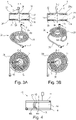
- 3A, 3B each show two different operating positions of the rotary guide 1 with a line section 2a accommodated therein at the top (front view) and bottom (top view) of the drawing area. Centered on the drawing area in the 3A, 3B the line section 2a is shown (in a perspective view) as it runs in the rotary guide 1 between points 3 and 4 (but without the rotary guide 1 for a better overview).
- the lower point 4 of the line 2 is stationary, the upper point 3 of the line 2 is rotated about the axis of rotation X relative to the lower point 4 .
- the upper receiving part 12 of the rotary guide 1 rotates about the axis of rotation X together with the point 4 relative to the lower receiving part 14 which in the illustrated example is stationary or fixed to a stationary surface not shown.
- the line section 2a can be locked close to the point 3 on the receiving part 12 or close to the innermost turn 36 in the longitudinal direction of the line 2 .
- the other section can also be locked close to point 4 .
- FIG.3A shows an exemplary operating position of the rotary guide 1, in which the recorded line section 2a is largely in the receiving part 14, in the 3A, 3B the resting lower receiving part, and all turns from the outermost turn 38 to the innermost turn 36 of the lower receiving groove 22, ie from the end radius r e almost to the beginning radius r a of the lower receiving groove 22 almost fills.
- the section 31 of the line section 2a accommodated in the lower receiving part 14 is much larger or longer than the section 29 accommodated in the upper receiving part 12.
- the two opposite sections 29, 31 are connected by the deflection area 18, in which the line 2 is turned over or deflected.
- these sections migrate in the longitudinal direction of the line 2 and merge into one another.
- the deflection area rotates in the circumferential direction and shifts in the radial direction.
- the deflection area 18 also rotates counterclockwise and migrates in the radial direction away from the axis of rotation X, ie its radial distance from the axis of rotation X increases, namely from the initial radius r a to the end radius r e of the receiving grooves 20, 22, as can be seen from comparison of 3A and 3B able to see.
- the deflection area 18 rests with its inner surface with respect to its deflection axis on the first boundary surface 28a of the guide slot 28, as shown in FIG FIG. 1B or. FIG.4 shown.
- the deflection area 18 is supported by the deflection guide of the deflection unit 16, namely the first boundary surface 28a, which is semi-cylindrical and convex.
- the deflection unit 16 is also rotated in the same direction. Since the first boundary surface 28a of the deflection unit 16 extends in the radial direction from the initial radius ra to the end radius re, the deflection area 18 is continuously supported by the first boundary surface 28a when it is wound around in the upper receiving groove 20 .
- the first boundary surface 28a of the guide slot 28 has a second function, namely as part of the active surface 33 which cooperates with the receiving groove 20 when the line section 2a is wound into the upper receiving groove 20.
- the effective surface 33 includes the part of the first boundary surface 28a that borders on the planar side 25, and also extends from the initial radius r a to the end radius r e in the radial direction. Therefore, the line portion 2a when folded into the turns of the upper receiving groove 20 is continuously supported by the active surface 33 over the radial extent of the receiving groove 20 .
- the deflection area 18 moves in the radial direction along the co-rotating effective surface 33 and is suitably positioned with each revolution for the next winding of the receiving groove 12 to be filled.
- Another part of the active surface 33, which faces the upper receiving groove 20, is level as part of the flat side 25 of the deflection unit 16, is flush with the flat main side 21 of the upper receiving part 12 and covers the receiving groove 20 from below, so that the longitudinal section of the line section 2a introduced into the receiving groove 20 during rotation is enclosed or secured in the receiving groove 20 in the axial direction or is limited in its freedom of movement in the axial direction and cannot fall out.
- the deflection area 18 rests with its outer surface with respect to its deflection axis on the second boundary surface 28b of the guide slot 28 .
- the second, lower area of the co-rotating active surface 33 which is in the FIG.2B is not visible, interacts with the lower receiving groove 22 in order to support the wrapping of the line section 2a in the receiving part 14 .
Landscapes
- Engineering & Computer Science (AREA)
- General Engineering & Computer Science (AREA)
- Mechanical Engineering (AREA)
- Electric Cable Arrangement Between Relatively Moving Parts (AREA)
- Storage Of Web-Like Or Filamentary Materials (AREA)
- Storing, Repeated Paying-Out, And Re-Storing Of Elongated Articles (AREA)
- Supports For Pipes And Cables (AREA)
- Pivots And Pivotal Connections (AREA)
- Rigid Pipes And Flexible Pipes (AREA)
- Steering Controls (AREA)
- Guides For Winding Or Rewinding, Or Guides For Filamentary Materials (AREA)
Claims (15)
- Guide rotatif (1) pour un guidage sans interruption d'au moins une conduite (2) entre deux points rotatifs l'un par rapport à l'autre (3, 4), le guide rotatif (1) comprenant :deux parties de réception (12, 14), positionnées rotatives l'une par rapport à l'autre autour d'un axe de rotation commun (X), pour loger respectivement une de deux sections partielles (29, 31) qui doivent être enroulées en sens contraire autour de l'axe de rotation commun (X) d'une section de conduite (2a) qui peut être logée dans le guide rotatif (1)et une unité de renvoi (16) pour supporter une zone de renvoi (18) dans laquelle la section de conduite (2a) de la conduite à guider (2) peut être retournée entre les sections partielles (29, 31) qui doivent être enroulées en sens contraire si bien que la au moins une conduite à guider (2) est renvoyée par une partie de réception (12, 14) dans l'autre partie de réception (12, 14) lors d'une rotation relative des parties de réception (12, 14) autour de l'axe de rotation commun (X), caractérisé en ceque chacune des parties de réception (12, 14) présente une rainure de réception en forme de spirale (20, 22) avec une multitude d'enroulements (24, 26) autour de l'axe de rotation commun (X) et qui s'étendent d'un rayon de début (ra) à un rayon de fin (re) pour recevoir une section de conduite (2a) au moins partiellement dans la rainure de réception (20, 22) de chaque partie de réception (12, 14) respectivement dans un plan prédéfini par la partie de réception (12, 14) perpendiculairement à l'axe de rotation commun (X) etque l'unité de renvoi (16) présente au moins une surface active (33) qui est étendue radialement ou qui est réglable radialement entre le rayon de début (ra) et le rayon de fin (re) qui coopère avec les rainures de réception (20, 22) des parties de réception (!2, 14) pour enrouler, lors d'une rotation relative des parties de réception (12, 14) autour de l'axe de rotation commun (X), la section de conduite (2a) de la au moins une conduite à guider (2) hors de la rainure de réception (20, 22) de l'une des parties de réception (12, 14) dans la rainure de réception (20, 22) de l'autre partie de réception (12, 14).
- Guide rotatif (1) selon la revendication 1, caractérisé en ce que- l'unité de renvoi (16) est placée rotative entre les parties de réception (12, 14) de telle manière qu'une des deux parties de réception (12, 14) est positionnée à l'aide de l'unité de renvoi (16) en rotation relative sur l'autre partie de réception (12, 14) et/ou- que l'unité de renvoi (16) présente un guidage de renvoi (28a, 28b) qui comprend de préférence au moins une partie de la surface active (33).
- Guide rotatif (1) selon la revendication 1 ou 2, caractérisé en ce que l'unité de renvoi (16) est réalisée de type plateau avec deux côtés en particulier substantiellement plans (25, 27), cependant que chacun des côtés (25, 27) de respectivement une rainure de réception (20, 22) est tourné respectivement vers l'une des parties de réception (12, 14) et se termine de préférence en affleurant avec une surface antagoniste correspondante des parties de réception (12, 14) pour couvrir et/ou limiter axialement la rainure de réception (20, 22).
- Guide rotatif (1) selon la revendication 2 ou 3, caractérisé en ce que le guidage de renvoi est configuré par des surfaces limites (28a, 28b ; 48a, 48b) d'une fente de guidage (28, 48) dans l'unité de renvoi (16) avec une extension radiale et une extension axiale.
- Guide rotatif (1) selon la revendication 4, caractérisé en ce qu'une première surface limite (28a ; 48a) de la fente de guidage (28 ; 48) est configurée comme surface limite convexe d'un demi cylindre avec un axe de cylindre qui s'étend perpendiculairement, en particulier radialement, par rapport à l'axe de rotation (X), cependant que la seconde surface limite (28b ; 48b) de la fente de guidage (28 ; 48), opposée dans une direction circonférentielle de la première surface limite (28a ; 48a), s'étend dans un plan de coupe perpendiculairement à l'axe de rotation (X) parallèlement à la première surface limite (28a ; 48a), et de préférence comme surface concave, en particulier conjuguée à la surface convexe semi-cylindrique, cependant que la première surface limite (28a ; 48a) forme de préférence une partie de la surface active (33) et cependant que de manière particulièrement préférée les côtés plans (25, 27) de l'unité de renvoi (16) forment une autre partie de la surface active (33).
- Guide rotatif (1) selon l'une des revendications précédentes, caractérisé en ce que le rayon de courbure dans la zone terminale la plus à l'intérieur des enroulements (24, 26) de la rainure de réception (20, 22) est supérieur ou égal au rayon minimal encore admissible de la zone de renvoi (18) de la conduite à guider (2).
- Guide rotatif (1) selon l'une des revendications précédentes, caractérisé en ce que l'extension axiale de l'unité de renvoi (16) est supérieure ou égale au double du rayon minimal encore admissible de la zone de renvoi (18) de la conduite à guider (2) et que les parties de réception (12, 14) présentent une extension axiale plus faible que l'unité de renvoi (16).
- Guide rotatif (1) selon l'une des revendications précédentes, caractérisé en ce que chacune des parties de réception (12, 14) est réalisée de type plateau avec deux côtés principaux (21, 21a, 23, 23a), cependant que la rainure de réception (20, 22) est ouverte vers l'un des côtés principaux (21, 23) et termine ce côté principal (21, 23) de préférence à plat.
- Guide rotatif (1) selon l'une des revendications précédentes, caractérisé en ce que le jeu axial entre les parties de réception (12, 14) et l'unité de renvoi (16) est réglable, de préférence réglable en continu.
- Guide rotatif (1) selon l'une des revendications précédentes, caractérisé en ce que la profondeur de la rainure de réception (20, 22) est adaptée au diamètre d'une conduite à guider (2).
- Guide rotatif (1) selon l'une des revendications précédentes, caractérisé en ce que des enroulements (24, 26) des deux rainures de réception (20, 22) s'étendent conformément à une spirale plane, en particulier conformément à une spirale d'Archimède.
- Guide rotatif (1) selon l'une des revendications précédentes, caractérisé en ce qu'au moins une partie de réception (12, 14) présente une ouverture de passage (7) vers l'enroulement le plus à l'intérieur et de préférence de plus caractérisé en ce que l'ouverture de passage est réalisée comme une fente radiale (51) d'un bord d'un petit côté (17, 19) de la partie de réception (12, 14) à l'enroulement le plus à l'intérieur.
- Guide rotatif (1) selon l'une des revendications précédentes, caractérisé en ce- que les parties de réception (12, 14) sont des pièces identiques et/ou- que le guide rotatif (1) est constitué par les parties de réception (12, 14) et l'unité de renvoi (16).
- Guide rotatif (1) selon l'une des revendications précédentes, caractérisé en ce que les parties de réception (12, 14) et l'unité de renvoi (16) sont fabriquées en matière plastique, en particulier par moulage par injection.
- Guide rotatif (1) selon l'une des revendications précédentes, caractérisé en ce que plusieurs conduites sont logées dans un dispositif de guidage de conduite pouvant être déployée dans l'espace et/ou dans une gaine souple ou équivalent qui est à son tour placée dans le guide rotatif.
Applications Claiming Priority (2)
| Application Number | Priority Date | Filing Date | Title |
|---|---|---|---|
| DE202019105125.6U DE202019105125U1 (de) | 2019-09-16 | 2019-09-16 | Drehführung für eine oder mehrere Leitungen |
| PCT/EP2020/075192 WO2021052833A1 (fr) | 2019-09-16 | 2020-09-09 | Guidage rotatif pour une ou plusieurs lignes |
Publications (2)
| Publication Number | Publication Date |
|---|---|
| EP4031790A1 EP4031790A1 (fr) | 2022-07-27 |
| EP4031790B1 true EP4031790B1 (fr) | 2023-03-01 |
Family
ID=72517225
Family Applications (1)
| Application Number | Title | Priority Date | Filing Date |
|---|---|---|---|
| EP20772012.9A Active EP4031790B1 (fr) | 2019-09-16 | 2020-09-09 | Guidage rotatif pour une ou plusieurs lignes |
Country Status (7)
| Country | Link |
|---|---|
| US (1) | US11975941B2 (fr) |
| EP (1) | EP4031790B1 (fr) |
| JP (1) | JP7583793B2 (fr) |
| KR (1) | KR102843727B1 (fr) |
| CN (1) | CN114555502B (fr) |
| DE (1) | DE202019105125U1 (fr) |
| WO (1) | WO2021052833A1 (fr) |
Families Citing this family (2)
| Publication number | Priority date | Publication date | Assignee | Title |
|---|---|---|---|---|
| KR102697221B1 (ko) * | 2021-12-15 | 2024-08-22 | 한국전력공사 | 컴팩트형 케이블 수납장치 |
| DE202023106221U1 (de) * | 2023-10-27 | 2025-01-30 | Igus Gmbh | Drehmodul zur Führung mindestens einer Leitung und Drehmodul mit mindestens einer Leitung |
Family Cites Families (18)
| Publication number | Priority date | Publication date | Assignee | Title |
|---|---|---|---|---|
| DE3008544A1 (de) | 1980-03-06 | 1981-09-17 | Felten & Guilleaume Carlswerk AG, 5000 Köln | Torsionsfreie speichervorrichtung fuer strangfoermiges gut zur verbindung von zwei sich gegeneinander drehenden anlagenteilen |
| DE3237581C2 (de) * | 1982-10-09 | 1984-09-06 | Atlanta-Kabel-Steinmüller KG, 5880 Lüdenscheid | Elektrische Leitungskupplung mit begrenzter Drehbarkeit |
| US4744763A (en) * | 1986-04-15 | 1988-05-17 | Furukawa Electric Co., Ltd. | Connector device for a transmission line connecting two relatively rotating members |
| JPH02215071A (ja) * | 1989-02-14 | 1990-08-28 | Furukawa Electric Co Ltd:The | コネクタ装置 |
| JPH08306458A (ja) * | 1995-05-02 | 1996-11-22 | Yazaki Corp | 回転体と固定体との間の電気的接続装置 |
| JP3538297B2 (ja) * | 1997-06-17 | 2004-06-14 | 株式会社オートネットワーク技術研究所 | 回転接続装置 |
| DE20305679U1 (de) | 2003-04-07 | 2003-06-18 | Igus Spritzgußteile für die Industrie GmbH, 51147 Köln | Kabelführung |
| US7108216B2 (en) * | 2003-04-11 | 2006-09-19 | Telefonix, Inc. | Retractable cord reels for use with flat electrical cable |
| DE102006009167B4 (de) | 2006-02-24 | 2007-11-08 | Tyco Electronics Amp Gmbh | Drehverbinder |
| DE202008001628U1 (de) * | 2008-02-05 | 2009-06-25 | Dunger, Steffen | Einrichtung zum Verbinden von rotierenden Kabeln |
| US8474742B2 (en) * | 2009-07-30 | 2013-07-02 | Adc Telecommunications, Inc. | Spool for telecommunications cable and method |
| DE202011103263U1 (de) | 2011-07-11 | 2011-09-23 | Igus Gmbh | Leitungsführungssystem |
| DE102012216372A1 (de) | 2012-09-14 | 2014-03-20 | BSH Bosch und Siemens Hausgeräte GmbH | Kältegerät mit einer Eis- oder Wasserausgabe |
| DE202013101460U1 (de) | 2013-04-05 | 2013-04-22 | Igus Gmbh | Leitungsführung aus mehrachsig abwinkelbaren Gliedern |
| DE202016102087U1 (de) | 2016-04-20 | 2017-05-26 | Igus Gmbh | Leitungsführungssystem für mindestens eine auf- und abspulbare Versorgungsleitung sowie Drehführung hierfür |
| DE202016102154U1 (de) * | 2016-04-22 | 2017-07-26 | Igus Gmbh | Kettenglied für Energieführungskette und Energieführungskette |
| DE202016105507U1 (de) | 2016-10-04 | 2017-11-07 | Igus Gmbh | Drehdurchführung für Leitungen |
| DE202016105840U1 (de) * | 2016-10-18 | 2017-11-23 | Igus Gmbh | Schnelllauf-Hubvorrichtung mit Versorgungsleitung und Energieführungskette hierfür |
-
2019
- 2019-09-16 DE DE202019105125.6U patent/DE202019105125U1/de active Active
-
2020
- 2020-09-09 JP JP2022513867A patent/JP7583793B2/ja active Active
- 2020-09-09 WO PCT/EP2020/075192 patent/WO2021052833A1/fr not_active Ceased
- 2020-09-09 CN CN202080064961.2A patent/CN114555502B/zh active Active
- 2020-09-09 EP EP20772012.9A patent/EP4031790B1/fr active Active
- 2020-09-09 US US17/761,078 patent/US11975941B2/en active Active
- 2020-09-09 KR KR1020227010628A patent/KR102843727B1/ko active Active
Also Published As
| Publication number | Publication date |
|---|---|
| US11975941B2 (en) | 2024-05-07 |
| KR20220063193A (ko) | 2022-05-17 |
| KR102843727B1 (ko) | 2025-08-07 |
| EP4031790A1 (fr) | 2022-07-27 |
| DE202019105125U1 (de) | 2020-10-21 |
| CN114555502A (zh) | 2022-05-27 |
| JP2022547835A (ja) | 2022-11-16 |
| WO2021052833A1 (fr) | 2021-03-25 |
| CN114555502B (zh) | 2024-09-27 |
| JP7583793B2 (ja) | 2024-11-14 |
| US20220340394A1 (en) | 2022-10-27 |
Similar Documents
| Publication | Publication Date | Title |
|---|---|---|
| EP3445695B1 (fr) | Système de guidage de ligne pour au moins une ligne d'alimentation pouvant être bobinée et dévidée ainsi que guidage rotatif associé | |
| EP3947228B1 (fr) | Dispositif d'enroulement compact pour une conduite flexible | |
| DE102011008879B4 (de) | Förderspindelmechanismus | |
| DE4004233A1 (de) | Verbindungsvorrichtung | |
| WO2020089685A1 (fr) | Dispositif de commande d'endoscope et endoscope équipé d'un dispositif de commande d'endoscope | |
| EP4031790B1 (fr) | Guidage rotatif pour une ou plusieurs lignes | |
| EP2624390A2 (fr) | Système de guidage de conduites destiné à la réception et au guidage de conduites d'alimentation ainsi que machine-outil | |
| EP2976814B1 (fr) | Équerre d'enfichage pour un connecteur enfichable | |
| DE602005003253T2 (de) | Schwenkbarer Drehtisch für Werkzeugmaschine, mit Kabelführung | |
| DE60014874T2 (de) | Schachtelähnlicher behälter mit einer haltevorrichtung für haspel mit aufgewickelter elektrischer leitung oder ähnlichem strangförmigen material das von der haspel abgewickelt werden kann | |
| DE19905756C2 (de) | Geschichtetes Flachband-Kopplungskabel für eine Rotationskopplungsvorrichtung | |
| EP2720970B1 (fr) | Dispositif pour dérouler et enrouler une ou plusieurs lignes | |
| EP4077184B1 (fr) | Système d'alimentation en énergie | |
| DE3810967C2 (fr) | ||
| DE3008544A1 (de) | Torsionsfreie speichervorrichtung fuer strangfoermiges gut zur verbindung von zwei sich gegeneinander drehenden anlagenteilen | |
| WO2019193072A1 (fr) | Passage tournant modulaire avec chaînes de guidage d'énergie | |
| DE2629359C2 (de) | Gleitlager mit geteiltem Gehäuse | |
| DE4121137C2 (fr) | ||
| WO2018065377A1 (fr) | Passage tournant pour lignes ou conduits | |
| EP2548831A2 (fr) | Réservoir de puissance pour la réception d'une conduite électrique, optique ou fluidique | |
| DE1945295A1 (de) | Vorrichtung zur Energiezuleitung zu auf kreisfoermigen Bahnen beweglichen Verbrauchern | |
| DE202023106221U1 (de) | Drehmodul zur Führung mindestens einer Leitung und Drehmodul mit mindestens einer Leitung | |
| DE202020106401U1 (de) | Ausgabevorrichtung für eine flexible Leitungsanordnung und Leitungsführungseinrichtung mit Fördereinheit | |
| EP2063503A2 (fr) | Presse de sertissage | |
| EP1511921A1 (fr) | Entrainement de soupape force |
Legal Events
| Date | Code | Title | Description |
|---|---|---|---|
| STAA | Information on the status of an ep patent application or granted ep patent |
Free format text: STATUS: UNKNOWN |
|
| STAA | Information on the status of an ep patent application or granted ep patent |
Free format text: STATUS: THE INTERNATIONAL PUBLICATION HAS BEEN MADE |
|
| PUAI | Public reference made under article 153(3) epc to a published international application that has entered the european phase |
Free format text: ORIGINAL CODE: 0009012 |
|
| STAA | Information on the status of an ep patent application or granted ep patent |
Free format text: STATUS: REQUEST FOR EXAMINATION WAS MADE |
|
| 17P | Request for examination filed |
Effective date: 20220222 |
|
| AK | Designated contracting states |
Kind code of ref document: A1 Designated state(s): AL AT BE BG CH CY CZ DE DK EE ES FI FR GB GR HR HU IE IS IT LI LT LU LV MC MK MT NL NO PL PT RO RS SE SI SK SM TR |
|
| GRAP | Despatch of communication of intention to grant a patent |
Free format text: ORIGINAL CODE: EPIDOSNIGR1 |
|
| STAA | Information on the status of an ep patent application or granted ep patent |
Free format text: STATUS: GRANT OF PATENT IS INTENDED |
|
| DAV | Request for validation of the european patent (deleted) | ||
| DAX | Request for extension of the european patent (deleted) | ||
| INTG | Intention to grant announced |
Effective date: 20220914 |
|
| GRAS | Grant fee paid |
Free format text: ORIGINAL CODE: EPIDOSNIGR3 |
|
| GRAA | (expected) grant |
Free format text: ORIGINAL CODE: 0009210 |
|
| STAA | Information on the status of an ep patent application or granted ep patent |
Free format text: STATUS: THE PATENT HAS BEEN GRANTED |
|
| AK | Designated contracting states |
Kind code of ref document: B1 Designated state(s): AL AT BE BG CH CY CZ DE DK EE ES FI FR GB GR HR HU IE IS IT LI LT LU LV MC MK MT NL NO PL PT RO RS SE SI SK SM TR |
|
| REG | Reference to a national code |
Ref country code: GB Ref legal event code: FG4D Free format text: NOT ENGLISH |
|
| REG | Reference to a national code |
Ref country code: CH Ref legal event code: EP Ref country code: AT Ref legal event code: REF Ref document number: 1551183 Country of ref document: AT Kind code of ref document: T Effective date: 20230315 |
|
| REG | Reference to a national code |
Ref country code: DE Ref legal event code: R096 Ref document number: 502020002647 Country of ref document: DE |
|
| REG | Reference to a national code |
Ref country code: IE Ref legal event code: FG4D Free format text: LANGUAGE OF EP DOCUMENT: GERMAN |
|
| REG | Reference to a national code |
Ref country code: NL Ref legal event code: FP |
|
| REG | Reference to a national code |
Ref country code: LT Ref legal event code: MG9D |
|
| P01 | Opt-out of the competence of the unified patent court (upc) registered |
Effective date: 20230526 |
|
| PG25 | Lapsed in a contracting state [announced via postgrant information from national office to epo] |
Ref country code: RS Free format text: LAPSE BECAUSE OF FAILURE TO SUBMIT A TRANSLATION OF THE DESCRIPTION OR TO PAY THE FEE WITHIN THE PRESCRIBED TIME-LIMIT Effective date: 20230301 Ref country code: NO Free format text: LAPSE BECAUSE OF FAILURE TO SUBMIT A TRANSLATION OF THE DESCRIPTION OR TO PAY THE FEE WITHIN THE PRESCRIBED TIME-LIMIT Effective date: 20230601 Ref country code: LV Free format text: LAPSE BECAUSE OF FAILURE TO SUBMIT A TRANSLATION OF THE DESCRIPTION OR TO PAY THE FEE WITHIN THE PRESCRIBED TIME-LIMIT Effective date: 20230301 Ref country code: LT Free format text: LAPSE BECAUSE OF FAILURE TO SUBMIT A TRANSLATION OF THE DESCRIPTION OR TO PAY THE FEE WITHIN THE PRESCRIBED TIME-LIMIT Effective date: 20230301 Ref country code: HR Free format text: LAPSE BECAUSE OF FAILURE TO SUBMIT A TRANSLATION OF THE DESCRIPTION OR TO PAY THE FEE WITHIN THE PRESCRIBED TIME-LIMIT Effective date: 20230301 Ref country code: ES Free format text: LAPSE BECAUSE OF FAILURE TO SUBMIT A TRANSLATION OF THE DESCRIPTION OR TO PAY THE FEE WITHIN THE PRESCRIBED TIME-LIMIT Effective date: 20230301 |
|
| PG25 | Lapsed in a contracting state [announced via postgrant information from national office to epo] |
Ref country code: SE Free format text: LAPSE BECAUSE OF FAILURE TO SUBMIT A TRANSLATION OF THE DESCRIPTION OR TO PAY THE FEE WITHIN THE PRESCRIBED TIME-LIMIT Effective date: 20230301 Ref country code: PL Free format text: LAPSE BECAUSE OF FAILURE TO SUBMIT A TRANSLATION OF THE DESCRIPTION OR TO PAY THE FEE WITHIN THE PRESCRIBED TIME-LIMIT Effective date: 20230301 Ref country code: GR Free format text: LAPSE BECAUSE OF FAILURE TO SUBMIT A TRANSLATION OF THE DESCRIPTION OR TO PAY THE FEE WITHIN THE PRESCRIBED TIME-LIMIT Effective date: 20230602 Ref country code: FI Free format text: LAPSE BECAUSE OF FAILURE TO SUBMIT A TRANSLATION OF THE DESCRIPTION OR TO PAY THE FEE WITHIN THE PRESCRIBED TIME-LIMIT Effective date: 20230301 |
|
| PG25 | Lapsed in a contracting state [announced via postgrant information from national office to epo] |
Ref country code: SM Free format text: LAPSE BECAUSE OF FAILURE TO SUBMIT A TRANSLATION OF THE DESCRIPTION OR TO PAY THE FEE WITHIN THE PRESCRIBED TIME-LIMIT Effective date: 20230301 Ref country code: RO Free format text: LAPSE BECAUSE OF FAILURE TO SUBMIT A TRANSLATION OF THE DESCRIPTION OR TO PAY THE FEE WITHIN THE PRESCRIBED TIME-LIMIT Effective date: 20230301 Ref country code: PT Free format text: LAPSE BECAUSE OF FAILURE TO SUBMIT A TRANSLATION OF THE DESCRIPTION OR TO PAY THE FEE WITHIN THE PRESCRIBED TIME-LIMIT Effective date: 20230703 Ref country code: EE Free format text: LAPSE BECAUSE OF FAILURE TO SUBMIT A TRANSLATION OF THE DESCRIPTION OR TO PAY THE FEE WITHIN THE PRESCRIBED TIME-LIMIT Effective date: 20230301 |
|
| PG25 | Lapsed in a contracting state [announced via postgrant information from national office to epo] |
Ref country code: SK Free format text: LAPSE BECAUSE OF FAILURE TO SUBMIT A TRANSLATION OF THE DESCRIPTION OR TO PAY THE FEE WITHIN THE PRESCRIBED TIME-LIMIT Effective date: 20230301 Ref country code: IS Free format text: LAPSE BECAUSE OF FAILURE TO SUBMIT A TRANSLATION OF THE DESCRIPTION OR TO PAY THE FEE WITHIN THE PRESCRIBED TIME-LIMIT Effective date: 20230701 |
|
| REG | Reference to a national code |
Ref country code: DE Ref legal event code: R097 Ref document number: 502020002647 Country of ref document: DE |
|
| PLBE | No opposition filed within time limit |
Free format text: ORIGINAL CODE: 0009261 |
|
| STAA | Information on the status of an ep patent application or granted ep patent |
Free format text: STATUS: NO OPPOSITION FILED WITHIN TIME LIMIT |
|
| PG25 | Lapsed in a contracting state [announced via postgrant information from national office to epo] |
Ref country code: SI Free format text: LAPSE BECAUSE OF FAILURE TO SUBMIT A TRANSLATION OF THE DESCRIPTION OR TO PAY THE FEE WITHIN THE PRESCRIBED TIME-LIMIT Effective date: 20230301 Ref country code: DK Free format text: LAPSE BECAUSE OF FAILURE TO SUBMIT A TRANSLATION OF THE DESCRIPTION OR TO PAY THE FEE WITHIN THE PRESCRIBED TIME-LIMIT Effective date: 20230301 |
|
| 26N | No opposition filed |
Effective date: 20231204 |
|
| PG25 | Lapsed in a contracting state [announced via postgrant information from national office to epo] |
Ref country code: LU Free format text: LAPSE BECAUSE OF NON-PAYMENT OF DUE FEES Effective date: 20230909 |
|
| REG | Reference to a national code |
Ref country code: BE Ref legal event code: MM Effective date: 20230930 |
|
| PG25 | Lapsed in a contracting state [announced via postgrant information from national office to epo] |
Ref country code: LU Free format text: LAPSE BECAUSE OF NON-PAYMENT OF DUE FEES Effective date: 20230909 Ref country code: MC Free format text: LAPSE BECAUSE OF FAILURE TO SUBMIT A TRANSLATION OF THE DESCRIPTION OR TO PAY THE FEE WITHIN THE PRESCRIBED TIME-LIMIT Effective date: 20230301 |
|
| REG | Reference to a national code |
Ref country code: IE Ref legal event code: MM4A |
|
| PG25 | Lapsed in a contracting state [announced via postgrant information from national office to epo] |
Ref country code: IE Free format text: LAPSE BECAUSE OF NON-PAYMENT OF DUE FEES Effective date: 20230909 |
|
| PG25 | Lapsed in a contracting state [announced via postgrant information from national office to epo] |
Ref country code: IE Free format text: LAPSE BECAUSE OF NON-PAYMENT OF DUE FEES Effective date: 20230909 |
|
| PG25 | Lapsed in a contracting state [announced via postgrant information from national office to epo] |
Ref country code: BE Free format text: LAPSE BECAUSE OF NON-PAYMENT OF DUE FEES Effective date: 20230930 |
|
| PGFP | Annual fee paid to national office [announced via postgrant information from national office to epo] |
Ref country code: NL Payment date: 20240920 Year of fee payment: 5 |
|
| PGFP | Annual fee paid to national office [announced via postgrant information from national office to epo] |
Ref country code: CZ Payment date: 20240827 Year of fee payment: 5 |
|
| PG25 | Lapsed in a contracting state [announced via postgrant information from national office to epo] |
Ref country code: BG Free format text: LAPSE BECAUSE OF FAILURE TO SUBMIT A TRANSLATION OF THE DESCRIPTION OR TO PAY THE FEE WITHIN THE PRESCRIBED TIME-LIMIT Effective date: 20230301 |
|
| PG25 | Lapsed in a contracting state [announced via postgrant information from national office to epo] |
Ref country code: BG Free format text: LAPSE BECAUSE OF FAILURE TO SUBMIT A TRANSLATION OF THE DESCRIPTION OR TO PAY THE FEE WITHIN THE PRESCRIBED TIME-LIMIT Effective date: 20230301 |
|
| PG25 | Lapsed in a contracting state [announced via postgrant information from national office to epo] |
Ref country code: CY Free format text: LAPSE BECAUSE OF FAILURE TO SUBMIT A TRANSLATION OF THE DESCRIPTION OR TO PAY THE FEE WITHIN THE PRESCRIBED TIME-LIMIT; INVALID AB INITIO Effective date: 20200909 |
|
| PG25 | Lapsed in a contracting state [announced via postgrant information from national office to epo] |
Ref country code: HU Free format text: LAPSE BECAUSE OF FAILURE TO SUBMIT A TRANSLATION OF THE DESCRIPTION OR TO PAY THE FEE WITHIN THE PRESCRIBED TIME-LIMIT; INVALID AB INITIO Effective date: 20200909 |
|
| REG | Reference to a national code |
Ref country code: CH Ref legal event code: U11 Free format text: ST27 STATUS EVENT CODE: U-0-0-U10-U11 (AS PROVIDED BY THE NATIONAL OFFICE) Effective date: 20251001 |
|
| PGFP | Annual fee paid to national office [announced via postgrant information from national office to epo] |
Ref country code: GB Payment date: 20250923 Year of fee payment: 6 |
|
| PGFP | Annual fee paid to national office [announced via postgrant information from national office to epo] |
Ref country code: FR Payment date: 20250924 Year of fee payment: 6 Ref country code: AT Payment date: 20250918 Year of fee payment: 6 |
|
| PG25 | Lapsed in a contracting state [announced via postgrant information from national office to epo] |
Ref country code: TR Free format text: LAPSE BECAUSE OF FAILURE TO SUBMIT A TRANSLATION OF THE DESCRIPTION OR TO PAY THE FEE WITHIN THE PRESCRIBED TIME-LIMIT Effective date: 20230301 |
|
| PGFP | Annual fee paid to national office [announced via postgrant information from national office to epo] |
Ref country code: DE Payment date: 20251128 Year of fee payment: 6 |
|
| PGFP | Annual fee paid to national office [announced via postgrant information from national office to epo] |
Ref country code: IT Payment date: 20250930 Year of fee payment: 6 |
|
| PGFP | Annual fee paid to national office [announced via postgrant information from national office to epo] |
Ref country code: CH Payment date: 20251001 Year of fee payment: 6 |
|
| REG | Reference to a national code |
Ref country code: DE Ref legal event code: R081 Ref document number: 502020002647 Country of ref document: DE Owner name: IGUS SE & CO. KG, DE Free format text: FORMER OWNER: IGUS GMBH, 51147 KOELN, DE |
|
| PG25 | Lapsed in a contracting state [announced via postgrant information from national office to epo] |
Ref country code: CZ Free format text: LAPSE BECAUSE OF NON-PAYMENT OF DUE FEES Effective date: 20250909 |