EP2724086B2 - Échangeur de chaleur - Google Patents
Échangeur de chaleur Download PDFInfo
- Publication number
- EP2724086B2 EP2724086B2 EP12735798.6A EP12735798A EP2724086B2 EP 2724086 B2 EP2724086 B2 EP 2724086B2 EP 12735798 A EP12735798 A EP 12735798A EP 2724086 B2 EP2724086 B2 EP 2724086B2
- Authority
- EP
- European Patent Office
- Prior art keywords
- tube
- side walls
- contact surface
- heat
- heat exchanger
- Prior art date
- Legal status (The legal status is an assumption and is not a legal conclusion. Google has not performed a legal analysis and makes no representation as to the accuracy of the status listed.)
- Active
Links
Images


Classifications
-
- F—MECHANICAL ENGINEERING; LIGHTING; HEATING; WEAPONS; BLASTING
- F24—HEATING; RANGES; VENTILATING
- F24H—FLUID HEATERS, e.g. WATER OR AIR HEATERS, HAVING HEAT-GENERATING MEANS, e.g. HEAT PUMPS, IN GENERAL
- F24H9/00—Details
- F24H9/12—Arrangements for connecting heaters to circulation pipes
-
- B—PERFORMING OPERATIONS; TRANSPORTING
- B23—MACHINE TOOLS; METAL-WORKING NOT OTHERWISE PROVIDED FOR
- B23P—METAL-WORKING NOT OTHERWISE PROVIDED FOR; COMBINED OPERATIONS; UNIVERSAL MACHINE TOOLS
- B23P15/00—Making specific metal objects by operations not covered by a single other subclass or a group in this subclass
- B23P15/26—Making specific metal objects by operations not covered by a single other subclass or a group in this subclass heat exchangers or the like
-
- B—PERFORMING OPERATIONS; TRANSPORTING
- B60—VEHICLES IN GENERAL
- B60H—ARRANGEMENTS OF HEATING, COOLING, VENTILATING OR OTHER AIR-TREATING DEVICES SPECIALLY ADAPTED FOR PASSENGER OR GOODS SPACES OF VEHICLES
- B60H1/00—Heating, cooling or ventilating devices
- B60H1/22—Heating, cooling or ventilating devices the heat source being other than the propulsion plant
- B60H1/2215—Heating, cooling or ventilating devices the heat source being other than the propulsion plant the heat being derived from electric heaters
- B60H1/2225—Heating, cooling or ventilating devices the heat source being other than the propulsion plant the heat being derived from electric heaters arrangements of electric heaters for heating air
-
- F—MECHANICAL ENGINEERING; LIGHTING; HEATING; WEAPONS; BLASTING
- F24—HEATING; RANGES; VENTILATING
- F24H—FLUID HEATERS, e.g. WATER OR AIR HEATERS, HAVING HEAT-GENERATING MEANS, e.g. HEAT PUMPS, IN GENERAL
- F24H3/00—Air heaters
- F24H3/02—Air heaters with forced circulation
- F24H3/04—Air heaters with forced circulation the air being in direct contact with the heating medium, e.g. electric heating element
- F24H3/0405—Air heaters with forced circulation the air being in direct contact with the heating medium, e.g. electric heating element using electric energy supply, e.g. the heating medium being a resistive element; Heating by direct contact, i.e. with resistive elements, electrodes and fins being bonded together without additional element in-between
- F24H3/0429—For vehicles
-
- F—MECHANICAL ENGINEERING; LIGHTING; HEATING; WEAPONS; BLASTING
- F24—HEATING; RANGES; VENTILATING
- F24H—FLUID HEATERS, e.g. WATER OR AIR HEATERS, HAVING HEAT-GENERATING MEANS, e.g. HEAT PUMPS, IN GENERAL
- F24H3/00—Air heaters
- F24H3/02—Air heaters with forced circulation
- F24H3/06—Air heaters with forced circulation the air being kept separate from the heating medium, e.g. using forced circulation of air over radiators
- F24H3/08—Air heaters with forced circulation the air being kept separate from the heating medium, e.g. using forced circulation of air over radiators by tubes
- F24H3/081—Air heaters with forced circulation the air being kept separate from the heating medium, e.g. using forced circulation of air over radiators by tubes using electric energy supply
-
- F—MECHANICAL ENGINEERING; LIGHTING; HEATING; WEAPONS; BLASTING
- F24—HEATING; RANGES; VENTILATING
- F24H—FLUID HEATERS, e.g. WATER OR AIR HEATERS, HAVING HEAT-GENERATING MEANS, e.g. HEAT PUMPS, IN GENERAL
- F24H9/00—Details
- F24H9/18—Arrangement or mounting of grates or heating means
- F24H9/1854—Arrangement or mounting of grates or heating means for air heaters
- F24H9/1863—Arrangement or mounting of electric heating means
- F24H9/1872—PTC resistor
-
- H—ELECTRICITY
- H05—ELECTRIC TECHNIQUES NOT OTHERWISE PROVIDED FOR
- H05B—ELECTRIC HEATING; ELECTRIC LIGHT SOURCES NOT OTHERWISE PROVIDED FOR; CIRCUIT ARRANGEMENTS FOR ELECTRIC LIGHT SOURCES, IN GENERAL
- H05B3/00—Ohmic-resistance heating
- H05B3/40—Heating elements having the shape of rods or tubes
- H05B3/42—Heating elements having the shape of rods or tubes non-flexible
- H05B3/48—Heating elements having the shape of rods or tubes non-flexible heating conductor embedded in insulating material
- H05B3/50—Heating elements having the shape of rods or tubes non-flexible heating conductor embedded in insulating material heating conductor arranged in metal tubes, the radiating surface having heat-conducting fins
-
- F—MECHANICAL ENGINEERING; LIGHTING; HEATING; WEAPONS; BLASTING
- F24—HEATING; RANGES; VENTILATING
- F24H—FLUID HEATERS, e.g. WATER OR AIR HEATERS, HAVING HEAT-GENERATING MEANS, e.g. HEAT PUMPS, IN GENERAL
- F24H2250/00—Electrical heat generating means
- F24H2250/04—Positive temperature coefficients [PTC]; Negative temperature coefficients [NTC]
-
- H—ELECTRICITY
- H05—ELECTRIC TECHNIQUES NOT OTHERWISE PROVIDED FOR
- H05B—ELECTRIC HEATING; ELECTRIC LIGHT SOURCES NOT OTHERWISE PROVIDED FOR; CIRCUIT ARRANGEMENTS FOR ELECTRIC LIGHT SOURCES, IN GENERAL
- H05B2203/00—Aspects relating to Ohmic resistive heating covered by group H05B3/00
- H05B2203/02—Heaters using heating elements having a positive temperature coefficient
-
- H—ELECTRICITY
- H05—ELECTRIC TECHNIQUES NOT OTHERWISE PROVIDED FOR
- H05B—ELECTRIC HEATING; ELECTRIC LIGHT SOURCES NOT OTHERWISE PROVIDED FOR; CIRCUIT ARRANGEMENTS FOR ELECTRIC LIGHT SOURCES, IN GENERAL
- H05B2203/00—Aspects relating to Ohmic resistive heating covered by group H05B3/00
- H05B2203/022—Heaters specially adapted for heating gaseous material
- H05B2203/024—Heaters using beehive flow through structures
-
- Y—GENERAL TAGGING OF NEW TECHNOLOGICAL DEVELOPMENTS; GENERAL TAGGING OF CROSS-SECTIONAL TECHNOLOGIES SPANNING OVER SEVERAL SECTIONS OF THE IPC; TECHNICAL SUBJECTS COVERED BY FORMER USPC CROSS-REFERENCE ART COLLECTIONS [XRACs] AND DIGESTS
- Y10—TECHNICAL SUBJECTS COVERED BY FORMER USPC
- Y10T—TECHNICAL SUBJECTS COVERED BY FORMER US CLASSIFICATION
- Y10T29/00—Metal working
- Y10T29/49—Method of mechanical manufacture
- Y10T29/49002—Electrical device making
- Y10T29/49082—Resistor making
- Y10T29/49083—Heater type
Definitions
- the invention relates to a heat exchanger according to the preamble of claim 1, a motor vehicle air conditioning system according to the preamble of claim 8 and a method for producing a heat exchanger or a motor vehicle air conditioning system according to the preamble of claim 9.
- Automotive air conditioning systems are used to heat and/or cool the air supplied to the interior of a motor vehicle.
- heat exchangers are used as electrical heating devices to heat the air supplied to the interior.
- the electrical heating device includes PTC elements.
- PTC elements PTC: Positive Temperature Coefficient
- PTC elements are current-conducting materials that have an electrical resistance and can conduct electricity better at lower temperatures than at higher temperatures. Their electrical resistance therefore increases as the temperature rises.
- the PTC element is generally made of ceramic and is a thermistor. This means that, regardless of the boundary conditions - such as the applied
- the heat exchanger comprises PTC elements, at least two electrical conductors by means of which electrical current is conducted through the PTC element and heat conducting elements, in particular lamellae or corrugated fins, by means of which the surface for heating the air is increased.
- Motor vehicles are increasingly being manufactured which have an exclusively electric drive or a hybrid drive.
- Motor vehicle air conditioning systems for these motor vehicles generally no longer have a heat exchanger for heating the air through which coolant flows.
- the entire heating power of the motor vehicle air conditioning system must therefore be provided by the electrical heating device or the PTC elements. For this reason, it is necessary to operate the PTC elements with high voltage, e.g. in the range of 50 to 600 volts, instead of low voltage with 12 volts.
- high voltage in a motor vehicle air conditioning system represents a safety problem because, for example, human contact with high-voltage parts can cause health damage to humans.
- the US 4,327,282 shows a heat exchanger with a PTC heating element. Current is passed through the PTC heating element using contact plates and an insulating layer is arranged on the contact plates. The components are held together using a U-shaped clip.
- a heat-generating element of a heating device for heating air comprising at least one PTC element and electrical conductor tracks lying on opposite side surfaces of the PTC element, wherein the two electrical conductor tracks are surrounded on the outside by a non-electrically conductive insulating layer.
- the EP 0 573 691 B1 reveals a heat exchanger.
- the US 6 455 822 B1 discloses a heat exchanger according to the preamble of claim 1.
- the object of the present invention is therefore to provide a heat exchanger and a motor vehicle air conditioning system as well as a method for producing a heat exchanger and a motor vehicle air conditioning system in which a heat exchanger operated with electrical current at high voltage, e.g. more than 50 V, can be operated without endangering the environment, in particular people.
- the heat exchanger and the motor vehicle air conditioning system should be inexpensive to manufacture and work reliably in operation.
- the pipe Before being pressed onto and deformed by the at least one electrical insulating element, the pipe is curved at the support surface in a section perpendicular to a longitudinal axis of the pipe and is then essentially flat, so that after being pressed onto the at least one electrical insulating element, a bending moment like that of a leaf spring is produced at the at least one support surface on the pipe and the heating assembly is thereby non-positively secured between the pipe.
- the at least one tube is designed as at least one flat tube with two broad side walls and two narrow side walls, and the two narrow side walls are braced by means of a compressive force acting on the two broad side walls on a support surface each, so that a heating assembly with at least one electrical resistance heating element, at least two conductors and at least one electrical insulating element is held force-fittingly between the two broad side walls.
- the pressure force on the at least one support surface in a section perpendicular to a longitudinal axis of the pipe is smaller at the edge than in the middle, in particular the pressure force is at least 10%, 30%, 50% or 100% greater in the middle than on the edge.
- the ratio between the central thickness of the tube on the at least one support surface and the edge thickness of the tube on the at least one support surface is greater than or equal to 1.0, and preferably less than 1.5 or 1.2 or 1.1.
- the greater thickness of the tube in the center of the support surface than at the edge means that a bending stress perpendicular to a longitudinal axis of the tube constantly occurs after pressing onto the at least one electrical insulating element.
- the ratio between the central thickness of the tube on the at least one support surface to the thickness of the tube outside the support surface is between 1.1 and 2.0, preferably between 1.1 and 1.5, in particular between 1.2 and 1.7.
- the tube thus has a shoulder between the support surface and outside the support surface, so that a compressive force is only applied to the at least one electrical insulating element on the support surface. Larger bending stresses on the at least one electrical insulating element, in particular designed as a ceramic plate, can thus be avoided and breakage of the ceramic plate can thus be essentially ruled out.
- the thickness of the tube on the at least one support surface is between 0.7 mm and 3 mm, preferably between 0.8 mm and 2 mm, in particular between 0.9 mm and 1.7 mm, and/or the tube is provided with a predetermined bending point, in particular on the two narrow side walls, wherein the tube preferably has a smaller thickness at the predetermined bending point than outside the predetermined bending point and/or the two narrow side walls are convexly curved on the outside and/or the two narrow side walls are bent outwards.
- the tube is generally flat on the two narrow side walls before the pressing process in the pressing tool and then curved outwards.
- the narrow side walls are bent in the pressing tool essentially at the predetermined bending points with a smaller thickness than outside the predetermined bending point.
- the thickness of the pipe at the predetermined bending point is at least 10%, 20%, 30% or 50% smaller than outside the at least one predetermined bending point, in particular on the two narrow side walls.
- the at least one heat conducting element comprises the at least one tube and/or the at least one heat conducting element comprises corrugated fins which are arranged on the outside of the at least one tube, in particular by means of soldering or gluing, and/or the at least two conductors have no direct contact with the at least one tube and/or the width of the at least one electrical insulating element is greater than the width of the at least one support surface of the tube and/or is greater than the width of the at least one conductor in a section perpendicular to the longitudinal axis of the tube.
- the at least one electrical insulating element consists at least partially, in particular completely, of ceramic and/or the at least one electrical insulating element is disk-shaped or plate-shaped, in particular rectangular.
- the at least one electrical resistance heating element, the at least two conductors and the at least one electrical insulating element are connected to form at least one heating assembly which is or are arranged within the at least one tube, and preferably several tubes, each with a heating assembly with corrugated fins arranged between the tubes, form the heat exchanger, wherein a compressive force is applied to the walls of the at least one tube, in particular the broad side walls of the at least one flat tube, in particular not by means of a clamping frame or a spring.
- Motor vehicle air conditioning system which comprises at least one heat exchanger described in this patent application.
- Method according to the invention according to claim 9, with the steps: providing at least one electrical resistance heating element, in particular at least one PTC element, providing at least two electrical conductors, in particular circuit boards, for conducting electrical current through the at least one electrical resistance heating element, providing at least one heat conducting element for transferring heat from the at least one electrical resistance heating element to a fluid to be heated, providing at least one electrical insulating element for electrically insulating the at least one heat conducting element from the at least two conductors, connecting the at least two conductors to the at least one electrical resistance heating element, thermally connecting the at least one heat conducting element to the at least two conductors and/or to the at least one electrical resistance heating element, electrically insulating the at least two conductors, preferably from the at least one heat conducting element, by means of the at least one electrical insulating element, by connecting the at least two conductors to the at least one electrical resistance heating element and the at least one electrical insulating element to form at least one heating assembly, wherein the at least one heat conducting element comprises at least one tube
- the pipe with the heating assembly is introduced into the pressing tool within the cavity, then the pipe is deformed and pressed onto the heating assembly using the pressing tool and then the pipe is removed from the pressing tool and/or the at least one pipe is provided as at least one flat pipe and the at least one heating assembly is introduced into the at least one cavity enclosed by the at least one flat pipe with a closed cross-section and then the flat pipe is deformed on the narrow side walls and thus also clamped so that the wide side walls of the flat tube are pressed onto the heating assembly, in particular onto the at least one electrical insulating element, under a compressive force.
- the pipe is deformed and pressed onto the heating compound on at least one support surface in the pressing tool and due to a convex curvature of the support surface in a section perpendicular to a longitudinal axis of the pipe, the pipe is first placed and pressed onto the heating compound in the middle of the at least one support surface and during further deformation and pressing in the pressing tool, the at least one support surface is also placed and pressed onto the heating compound on the edge and/or the pressing process is aborted in the pressing tool when a predetermined limit value of the pressing force is reached,
- the two narrow side walls are bent outwards, particularly at a predetermined bending point, during the pressing process in the pressing tool.
- the narrow side walls are deformed at a predetermined bending point and/or the narrow side walls are deformed by applying a compressive force from the pressing tool to the wide side walls and/or the pipe, in particular on the two narrow side walls, is provided with a predetermined bending point
- the pipe preferably has a smaller thickness at the predetermined bending point than outside the predetermined bending point and/or the pipe, in particular on the two narrow side walls, is provided with at least one convex support surface and/or the pipe is provided with a concave curve on the outside on a pressing surface opposite the at least one support surface and/or the pipe is provided in such a way that the ratio between the central thickness of the pipe on the at least one support surface to the edge thickness of the pipe on the at least one support surface is greater than or equal to 1.0 and preferably less than 1.5 or 1.2 or 1.1 and/or the pipe is provided in such a way that the ratio between the central thickness of the pipe on the at least one support surface to the thickness of the pipe outside the support
- the at least one heat-conducting element in particular the at least one tube and/or the corrugated fins, consist at least partially, in particular completely, of metal, for example aluminum or steel, or plastic
- the at least one electrical insulating element is arranged between a wall of the at least one tube and a conductor, so that the at least two conductors are electrically insulated with respect to the at least one tube.
- two, preferably essentially rectangular, molded seals are arranged in the cavity as electrical insulating elements or the at least one molded seal is designed in the cavity as a hose, in particular a shrink hose.
- the two essentially rectangular molded seals are clamped between a wide side wall of the at least one flat tube and a circuit board.
- the hose, in particular a shrink hose, which forms the molded seal encloses the heating unit with the two circuit boards and the PTC elements. The heating unit is thus electrically insulated.
- the at least one molded seal is expediently elastic and/or the at least one molded seal consists at least partially of silicone or plastic or rubber and/or the at least one molded seal is a film.
- the at least one molded seal comprises heat-transferring or heat-conducting particles, e.g. aluminum oxide and/or silicon carbide and/or boron nitride.
- the at least one tube is manufactured as at least one flat tube and the at least one heating compound is introduced into the at least one cavity enclosed by the at least one flat tube with a closed cross-section, and then the flat tube is deformed on the narrow side walls by a pressing tool and thus also clamped, so that the broad side walls of the flat tube are pressed onto the at least one electrical insulating element.
- the thickness of the at least one cavity between the two broad side walls is greater than the thickness of the heating assembly between the electrical insulating elements on the at least two conductors.
- the thickness of the heating assembly is preferably determined perpendicular to a plane spanned by the circuit boards.
- the shape of the wall of the tube is changed, in particular bent and/or braced, so that the volume of the at least one cavity is reduced and preferably the heating assembly is thereby non-positively connected to the broad side walls of the at least one flat tube.
- the at least one molded seal is a film or insulation film, e.g. a polyimide film (Kapton film), (elastic) ceramic-filled film or an (elastic) ceramic-filled silicone film.
- a film or insulation film e.g. a polyimide film (Kapton film), (elastic) ceramic-filled film or an (elastic) ceramic-filled silicone film.
- the heat exchanger has an IP protection class of 67, so that it is sufficiently watertight and dustproof.
- the corrugated fins and the at least one tube are connected to one another by means of gluing and/or soldering and/or force-fitting under prestress.
- the at least one heat-conducting element and/or the at least one electrical insulating element has a thermal conductivity of at least 0.5 W/mK, in particular at least 10 W/mK.
- the at least one electrical insulating element has an electrical insulation of at least 1 kV/mm, in particular at least 15 kV/mm.
- the at least one electrical insulating element has, preferably in cross-section, a dielectric strength of at least 1 kV.
- the at least one electrical insulating element has a thermal conductivity of at least 0.5 W/mK, in particular at least 10 W/mK.
- the at least one electrical insulating element can thus, on the one hand, provide good electrical insulation and, on the other hand, can conduct the heat sufficiently well from the electrical resistance heating element to the heat-conducting element or elements.
- Fig. 1 shows a motor vehicle air conditioning system 24.
- a blower 25, an air filter 30, a coolant evaporator 31 and a heat exchanger 1 as an electrical heating device are arranged in an air conditioning housing 26 with a bottom wall 27 and an outlet section 29.
- the air conditioning housing 26 thus forms a channel 35 for the passage of air.
- Housing walls 28 of the air conditioning housing 26 have a surface 36 on the inside, which delimits the channel 35.
- the air for the interior of a motor vehicle is passed through the air filter 30, the coolant evaporator 31 and the heat exchanger 1 by means of the blower 25.
- the motor vehicle air conditioning system 24 is therefore not provided with a heat exchanger through which coolant flows for heating the air conducted through the motor vehicle system 24.
- the air conducted through the motor vehicle air conditioning system 24 is heated electrically exclusively by means of the heat exchanger 1.
- the motor vehicle air conditioning system 24 is preferably used in a motor vehicle with an exclusively electric drive or with a hybrid drive (not shown).
- the heat exchanger 1 In order to achieve the necessary electrical heating output by means of the heat exchanger 1, the heat exchanger 1 must be operated with high voltage, e.g. with more than 50 volts, for example with 60 V or 600 V, in order to avoid excessive current intensities and thus excessively thick power lines (not shown).
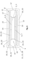
- a tube 18 made of aluminum, designed as a flat tube 13 with a longitudinal axis 34, has two broad side walls 20 and two narrow side walls 21 ( Fig. 5 , 6 and 8 ).
- the wide and narrow side walls 20, 21 represent walls 16 which enclose a cavity 19 within the tube 18.
- the walls 18 have no joints in the cross section, e.g. a tongue and groove connection, a weld or solder joint.
- the tube 18 is manufactured in one piece as a closed wall 18 by extrusion, so that no joints are required in the cross section of the tube 18.
- the two circuit boards 6, 7 with the three PTC elements 3 arranged between them are electrically insulated due to the electrical insulation of the ceramic plates 23.
- the electrical contact between the two circuit boards 6, 7 is made by means of electrical lines (not shown) on the contact plates 5.
- the two circuit boards 6, 7 with the three PTC elements 3 represent a heating unit 10. After the two ceramic plates 23 have been arranged on the heating unit 10, they form a heating assembly 8. After the heating assembly 8 has been introduced into the flat tubes 13 with the corrugated fins 12, a heating register 9 or the heat exchanger 1 is present.
- Several heating registers 9 as shown in Fig. 2 , 3 and 4 can also be connected to form a heat exchanger 1 with a larger number of heating registers 9.
- the network height H N of the heat exchanger 1 as shown in Fig. 3 and 4 is approximately 50 to 300 mm, preferably 100 to 200 mm and the net width B N is approximately 50 to 300 mm, preferably 100 to 200 mm.
- the transverse pitch Q ie the distance between the flat tubes 13 as shown in Fig. 4 , is between 5 and 30 mm, preferably 7 to 18 mm and the construction depth T N as shown in Fig. 4 is 6 to 50 mm, preferably 10 to 40 mm.
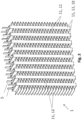
- corrugated fins 12 are arranged as heat conducting elements 11 ( Fig. 2 and 3 ).
- the corrugated fins 12 serve to enlarge the surface of the heat exchanger 1 in order to be able to better transfer the heat given off by the PTC elements 3 to the air flowing through the heat exchanger 1.
- the flat tubes 13 also represent heat conducting elements 11.
- the heating assembly 8, consisting of the two circuit boards 6, 7, the PTC elements 3 and the ceramic plates 23, is only pushed into the flat tube 13 after the flat tube 13 has been manufactured.
- the corrugated fins 12 are connected to the corrugated fins 12 after the heating assembly 8 has been inserted into the flat tube 13.
- the corrugated fins 12 can be connected to the flat tubes 13, for example, by gluing, welding or soldering.
- All flat tubes 13 of the heat exchanger 1 are sealed against dust and liquid from the surroundings of the heat exchanger 1, e.g. with cover plates on the upper and lower ends of the flat tubes (not shown) and/or with a sealing compound, e.g. a silicone seal.
- a sealing compound e.g. a silicone seal.
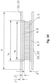
- Fig. 6 is the heating register 9 and in Fig. 9 only the flat tube 13 is shown before deformation and compression in a pressing tool 38.
- Fig. 8 the heating register 9 is shown after it has been removed from the pressing tool 38 and the flat tube 13 has been deformed and pressed on.
- the flat tube 13 is formed with a support surface 14 on the inside of the two wide side walls 20.
- the thickness of the tube 18 on the support surface 14 is greater than outside the support surface 14, so that a shoulder 17 is formed between the support surface 14 and outside the support surface 14 on the inside of the flat tube 13.
- the tube width B is between 4 mm and 10 mm, preferably between 5 mm and 8 mm, and the tube depth T is between 10 mm and 50 mm, preferably between 18 mm and 35 mm.
- the ratio between the pipe depth T and the pipe width B in the unpressed state according to Fig. 6 and 9 is approximately 3, but can also be between 2 and 5.5.
- the ratio between the pipe depth T and the pipe width B in the pressed state according to Fig. 8 after removal from the pressing tool 38 is approximately 3.3, but can also be in the range between 2.5 and 6.
- the two broad side walls 20 are as shown in Fig. 6 and 9 before insertion into the pressing tool 38 in the cuts according to Fig.
- the central thickness D 1 of the flat tube 13 is 1.0 mm and the edge thickness D 2 of the flat tube 13 on the support surface 14 is 0.95 mm.
- the ratio between the central thickness D 1 and the edge thickness D 2 is greater than 1, i.e. 1.05.
- the thickness D 3 of the tube 18 outside the support surface 14 is 0.8 mm, so that the ratio of D 1 to D 3 is 1.25.
- D 1 can also be between 1.0 mm and 1.2 mm in another embodiment, D 2 between 1.0 mm and 1.2 mm with a ratio of D 1 to D 2 of 1.0.
- D 3 is 0.8 mm and the ratio of D 1 to D 3 is between 1.25 and 1.5.
- D 1 and D 2 are each 1.5 mm, so that the ratio of D 1 to D 2 is 1.0 and D 3 has a thickness of 1.0 mm, so that the ratio of D 1 to D 3 is 1.5.
- the width S of the support surface 14 is in all embodiments greater than the width L B of the circuit boards 6,7 and smaller than the width I B of the electrical insulating element 22.
- the width H B of the electrical resistance heating element 2 is smaller than the width L B of the circuit boards 6,7 ( Fig. 10 ).
- the width I B of the electrical insulating element 22 is 2 mm to 8 mm larger than the width L B of the circuit boards 6, 7, so that no electrical arcing from the circuit boards 6, 7 to the flat tube 13 is possible.
- the flat tube 13 has an external concavity of K p of 0.2 mm before being deformed in the pressing tool 38.
- the external concavity K p is the vertical difference between a fictitious straight line parallel to the plane of the drawing of Fig. 9 , which rests on the outside of the broad side wall 20, and the middle of the pressing surface 15.
- the external concavity K p is between 0.05 mm and 0.5 mm.
- the thickness I D of the electrical insulating element 22 is between 0.3 mm and 1.5 mm
- the thickness L D of the circuit boards 6,7 is between 0.3 mm and 1.0 mm
- the thickness H D of the electrical resistance heating element 2 is between 1 mm and 3 mm, preferably between 1.5 mm and 2.5 mm ( Fig. 10 ).
- a pressure force 33 is applied by the pressing tool 38 to the two wide side walls 20 of the flat tube 13.
- the two narrow side walls 21 are formed as shown in Fig. 6 essentially perpendicular to the two broad side walls 20.
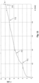
- Fig. 11 The path of the pressing tool 38 is plotted on the abscissa perpendicular to a plane spanned by the two broad side walls 20 and the force 33 applied by the pressing tool to the pipe 18 in kN is plotted on the ordinate.
- the two narrow side walls 21 are deformed outwards essentially at the two predetermined bending points 37.
- a first contact of the support surface 14 occurs, ie the upper support surface 14 as shown in Fig. 6 and 7 , with the upper electrical insulating element 22.
- the flat tube 13 no longer has any external concavity K p on the outside.
- the two broad side walls 20 have thus been deformed outwards, so that on the wide broad side walls 20 in the section perpendicular to the longitudinal axis 34 according to Fig.
- the two broad side walls 20 are thus pre-tensioned like a leaf spring and the heating assembly 8 is thus force-fitted between the two broad side walls 20 and the two broad side walls 20.
- This compressive force is applied by the two broad side walls 20 only at the support surface 14 to the two electrical insulating elements 22 as ceramic plates 23.
- the width S of the support surface 14 is only slightly larger than the width I B of the ceramic plate 23, so that essentially no bending moments and bending stresses occur on the brittle and hard ceramic plate 23 because the ceramic plate 23 is essentially only exposed to a compressive force between the support surface 14 and the two circuit boards 6, 7.
- the two narrow side walls 21 can be deformed outwards and, in addition, the two wide side walls 20 are pressed onto the two ceramic plates 23 due to a bending moment or a bending stress in the two wide side walls 20, so that they are held as a heating assembly 8 in a force-fitting manner between the two wide side walls 20.
- no clamping frame is required on the outside of the heat exchanger 1 for the force-fitting fastening of the heating assembly 8 in the flat tube 13.
- a force jump occurs in the fourth force section F4.
- the pressing tool 38 has fully pressed the flat tube 13 onto the heating assembly 8, so that the material of the flat tube 13 and also, for example, the electrical circuit boards 6, 7 flow from a central area of the support surface 14 to an edge area of the support surface 14.
- the pressing process can be aborted between the third force section F3 of approximately 10 kN and the fourth force section F4 of approximately 11.5 kN. From the force section F3 onwards, the flat tube 13 no longer has any external concavity kp on the outside. This means that the rib can be connected flatly to the flat tube.
- the heat exchanger 1 has significant advantages.
- the two narrow side walls 21 are curved before pressing in the pressing tool 38 and are deformed flat in the pressing tool 38 due to the flat design of the two ceramic plates 23, so that bending moments and a bending stress occur on the two wide side walls 20, which apply a compressive force to the heating assembly 8 on the support surface 14 and thus the heating assembly 8 is non-positively attached to the flat tube 13.
- the compressive forces applied by the support surface 14 to the ceramic plates 23 are significantly greater in the middle than at the edge, since the bending stress or the bending moment in a section perpendicular to the longitudinal axis 34 of the flat tube 13 are greater in the middle than at the edge.
- the two wide side walls 20 thus act like a leaf spring that is elastically prestressed, so that the two wide side walls 20 act like an elastic spring element.
Landscapes
- Engineering & Computer Science (AREA)
- Mechanical Engineering (AREA)
- Physics & Mathematics (AREA)
- Thermal Sciences (AREA)
- Chemical & Material Sciences (AREA)
- Combustion & Propulsion (AREA)
- General Engineering & Computer Science (AREA)
- Air-Conditioning For Vehicles (AREA)
- Resistance Heating (AREA)
- Direct Air Heating By Heater Or Combustion Gas (AREA)
- Heat-Exchange Devices With Radiators And Conduit Assemblies (AREA)
- Instantaneous Water Boilers, Portable Hot-Water Supply Apparatuses, And Control Of Portable Hot-Water Supply Apparatuses (AREA)
Claims (13)
- Echangeur de chaleur (1) comprenant :- au moins un élément chauffant à résistance électrique (2), en particulier au moins un élément (3) - CTP - à coefficient de température positif,- au moins deux conducteurs (4) - en particulier des plaques de circuits imprimés (6, 7) - connectés de manière électroconductrice à l'élément chauffant à résistance électrique (2) au moins au nombre de un, pour faire passer le courant électrique à travers l'élément chauffant à résistance électrique (2) au moins au nombre de un et, ainsi, chauffer l'élément chauffant à résistance électrique (2),- au moins un élément conducteur de la chaleur (11) servant à la transmission de chaleur à un fluide à chauffer, à partir de l'élément chauffant à résistance électrique (2) au moins au nombre de un,- au moins un élément isolant électrique (22) qui isole électriquement les conducteurs (4) au moins au nombre de deux, de l'élément conducteur de la chaleur (11) au moins au nombre de un,- au moins un tube (18), où- les conducteurs (4) au moins au nombre de deux et l'élément chauffant à résistance électrique (2) au moins au nombre de un sont disposés à l'intérieur d'un espace creux (19) délimité par le tube (18), et le tube (18), sous l'effet d'une force de compression s'exerçant sur au moins une surface d'appui (14), vient en appui sur l'élément isolant électrique (22) au moins au nombre de un,où le tube (18) s'appliquant sur la surface d'appui (14) au moins au nombre de un, en particulier perpendiculairement à un axe longitudinal (34) du tube (18) et parallèlement à un plan fictif défini par rapport à la surface d'appui (14), présente une épaisseur variable, où le tube (18) au moins au nombre de un est conçu comme un tube plat (13) comprenant deux parois à grands côtés (20) et deux parois à petits côtés (21), et les deux parois à petits côtés (21) sont serrées au moyen d'une force de compression s'exerçant à chaque fois sur une surface d'appui (14) s'appliquant sur les deux parois à grands côtés (20), de sorte qu'un ensemble chauffant combiné (8), qui comprend au moins un élément chauffant à résistance électrique (2), au moins deux conducteurs (4) et au moins un élément isolant électrique (22), est maintenu par action de force entre les deux parois à grands côtés (20), où le tube (18), au niveau des deux parois à petits côtés (21), est doté d'un point destiné au flambage (37), où le tube (18), au niveau du point destiné au flambage (37), présente une épaisseur inférieure à celle située à l'extérieur du point destiné au flambage (37), où l'élément chauffant à résistance électrique (2) au moins au nombre de un, les conducteurs (4) au moins au nombre de deux et l'élément isolant électrique (22) au moins au nombre de un sont assemblés pour former au moins un ensemble chauffant combiné (8), lequel ou lesquels ensemble(s) chauffant(s) combiné(s) est ou sont disposé(s) à l'intérieur du tube (18) au moins au nombre de un, caractérisé en ce que plusieurs tubes (18) comprenant chacun un ensemble chauffant combiné (8) et comprenant des ailettes ondulées (12) disposées entre les tubes (18) forment l'échangeur de chaleur (1), où une force de compression est appliquée, en particulier non pas au moyen d'un cadre de serrage ou non pas à l'aide d'un ressort, sur les parois (16) du tube (18) au moins au nombre de un, en particulier sur les parois à grands côtés (20) du tube plat (13) au moins au nombre de un.
- Echangeur de chaleur selon la revendication 1, caractérisé en ce que la force de compression s'exerçant sur la surface d'appui (14) au moins au nombre de un, dans une coupe perpendiculaire à un axe longitudinal (34) du tube (18), est inférieure, côté bordure, à celle s'exerçant au milieu, en particulier la force de compression s'exerçant au milieu est au moins de 10 %, de 30 %, de 50 % ou de 100 % supérieure à celle s'exerçant côté bordure.
- Echangeur de chaleur selon l'une ou plusieurs des revendications précédentes, caractérisé en ce que le rapport entre l'épaisseur au milieu du tube (18) s'appliquant sur la surface d'appui (14) au moins au nombre de un, et l'épaisseur sur le côté bordure du tube (18) s'appliquant sur la surface d'appui (14) au moins au nombre de un, est supérieur ou égal à 1,0 et, de préférence, inférieur à 1,5 ou à 1,2 ou à 1,1.
- Echangeur de chaleur selon l'une quelconque ou plusieurs des revendications précédentes, caractérisé en ce que le rapport entre l'épaisseur au milieu du tube (18) s'appliquant sur la surface d'appui (14) au moins au nombre de un, et l'épaisseur du tube (18) à l'extérieur de la surface d'appui (14), est compris entre 1,1 et 2,0, de préférence entre 1,1 et 1,5, en particulier compris entre 1,2 et 1,7.
- Echangeur de chaleur selon l'une quelconque ou plusieurs des revendications précédentes, caractérisé en ce que l'épaisseur du tube (18) s'appliquant sur la surface d'appui (14) au moins au nombre de un est comprise entre 0,7 mm et 3 mm, de préférence comprise entre 0,8 mm et 2 mm, en particulier comprise entre 0,9 mm et 1,7 mm et/ou le tube (18), en particulier sur les deux parois à petits côtés (21), est doté d'un point destiné au flambage (37), où le tube (18), au niveau du point destiné au flambage (37), présente de préférence une épaisseur inférieure à celle située à l'extérieur du point destiné au flambage (37) et/ou les deux parois à petits côtés (21) sont, sur le côté extérieur, courbées de façon convexe et/ou les deux parois à petits côtés (21) sont recourbées vers l'extérieur.
- Echangeur de chaleur selon l'une quelconque ou plusieurs des revendications précédentes, caractérisé en ce que l'élément conducteur de la chaleur (11) au moins au nombre de un comprend le tube (18) au moins au nombre de un et/ou l'élément conducteur de la chaleur (11) au moins au nombre de un comprend des ailettes ondulées (12) qui, placées sur le côté extérieur, sont disposées sur le tube (18) au moins au nombre de un, en particulier par brasage ou par collage, et/ou les conducteurs (4) au moins au nombre de deux ne présentent aucun contact direct avec le tube (18) au moins au nombre de un et/ou la largeur de l'élément isolant électrique (22) au moins au nombre de un est supérieure à la largeur de la surface d'appui (14) au moins au nombre de un du tube (18) et/ou supérieure à la largeur du conducteur (4) au moins au nombre de un, dans une coupe perpendiculaire à l'axe longitudinal (34) du tube (18) .
- Echangeur de chaleur selon l'une quelconque ou plusieurs des revendications précédentes, caractérisé en ce que l'élément isolant électrique (22) au moins au nombre de un se compose au moins en partie, en particulier en totalité, de céramique et/ou l'élément isolant électrique (22) au moins au nombre de un est configuré en forme de disque ou en forme de plaque, en particulier configuré de forme rectangulaire avec des encoches.
- Système de climatisation d'un véhicule automobile, caractérisé en ce que le système de climatisation du véhicule automobile comprend au moins un échangeur de chaleur (1) selon l'une quelconque ou plusieurs des revendications précédentes.
- Procédé de fabrication d'un échangeur de chaleur (1) selon l'une quelconque ou plusieurs des revendications 1 à 7, ou bien d'un système de climatisation d'un véhicule automobile selon la revendication 8, ledit procédé comprenant les étapes consistant :- à fournir au moins un élément chauffant à résistance électrique (2), en particulier au moins un élément CTP (3),- à fournir au moins deux conducteurs électriques (4), en particulier des plaques de circuits imprimés (6, 7), servant à faire passer le courant électrique à travers l'élément chauffant à résistance électrique (2) au moins au nombre de un,- à fournir au moins un élément conducteur de la chaleur (11) servant à la transmission de chaleur à un fluide à chauffer, à partir de l'élément chauffant à résistance électrique (2) au moins au nombre de un,- à fournir au moins un élément isolant électrique (22) servant à l'isolation électrique de l'élément conducteur de la chaleur (11) au moins au nombre de un, par rapport aux conducteurs (4) au moins au nombre de deux,- à connecter les conducteurs (4) au moins au nombre de deux, à l'élément chauffant à résistance électrique (2) au moins au nombre de un,- à assurer la liaison thermique de l'élément conducteur de la chaleur (11) au moins au nombre de un, avec les conducteurs (4) au moins au nombre de deux et/ou avec l'élément chauffant à résistance électrique (2) au moins au nombre de un,- à assurer l'isolation électrique des conducteurs (4) au moins au nombre de deux, de préférence par rapport à l'élément conducteur de la chaleur (11) au moins au nombre de un, au moyen de l'élément isolant électrique (22) au moins au nombre de un, tandis que les conducteurs (4) au moins au nombre de deux, associés à l'élément chauffant à résistance électrique (2) au moins au nombre de un et à l'élément isolant électrique (22) au moins au nombre de un, sont assemblés pour former au moins un ensemble chauffant combiné,- où il est prévu au moins l'élément conducteur de la chaleur (11) au moins au nombre de un et au moins un tube (18), où le tube (18) contient au moins un espace creux (19),- l'ensemble chauffant combiné (8), se trouvant à l'intérieur de l'espace creux (19), est fixé par action de force sur le tube (18), tandis que le tube (18) est déformé et comprimé sur l'ensemble chauffant combiné (8), en particulier sur l'élément isolant électrique (22) au moins au nombre de un, de sorte que le tube (18), sous l'effet d'une force de compression, est comprimé sur l'élément chauffant combiné (8), en particulier sur l'élément isolant électrique (22) au moins au nombre de un, où le tube (18) est déformé et comprimé sur l'ensemble chauffant combiné (8), à l'intérieur d'un outil de compression (38).
- Procédé selon la revendication 9, caractérisé en ce que le tube (18), avec l'ensemble chauffant combiné (8) contenu à l'intérieur de l'espace creux (19), est introduit dans l'outil de compression (38), puis, avec l'outil de compression (38), le tube (18) est déformé et comprimé sur l'ensemble chauffant combiné (8) et, ensuite, le tube (18) est sorti de l'outil de compression (38) et/ou le tube (18) au moins au nombre de un est fourni comme au moins un tube plat (13), et l'ensemble chauffant combiné (8) au moins au nombre de un est introduit dans l'espace creux (19) au moins au nombre de un qui est contenu par le tube plat (13) au moins au nombre de un, fermé en section, et, ensuite, le tube plat (13) est déformé contre les parois à petits côtés (21) et, ainsi, serré, de sorte que les parois à grands côtés (20) du tube plat (13), sous l'effet d'une force de compression, sont comprimées sur l'ensemble chauffant combiné (8), en particulier sur l'élément isolant électrique (22) au moins au nombre de un.
- Procédé selon la revendication 9 ou 10, caractérisé en ce que le tube (18) s'appliquant sur au moins une surface d'appui (14) est déformé et comprimé sur l'ensemble chauffant combiné (8) placé dans l'outil de compression (38) et, en raison d'une courbure convexe de la surface d'appui (14), dans une coupe perpendiculaire à un axe longitudinal (34) du tube (18), le tube (18), d'abord au milieu de la surface d'appui (14) au moins au nombre de un, est appliqué et comprimé sur l'ensemble chauffant combiné (8) et, au cours d'un autre processus de déformation et de compression se produisant dans l'outil de compression (38), la surface d'appui (14) au moins au nombre de un est appliquée et comprimée également, côté bordure, sur l'ensemble chauffant combiné (8) et/ou le processus de compression se produisant dans l'outil de compression (38) est arrêté quand une valeur limite prédéfinie de la force de compression a été atteinte.
- Procédé selon la revendication 10 ou selon les revendications 10 et 11, caractérisé en ce que les deux parois à petits côtés (21), en particulier au niveau d'un point destiné au flambage (37), sont recourbées vers l'extérieur au cours du processus de compression se produisant dans l'outil de compression (38) .
- Procédé selon la revendication 10, selon les revendications 10 et 11 ou selon la revendication 12, caractérisé en ce que les parois à petits côtés (21) sont déformées au niveau d'un point destiné au flambage (37) et/ou les parois à petits côtés (21) sont déformées, tandis qu'une force de compression est appliquée, par l'outil de compression (38), sur les parois à grands côtés (20), et/ou le tube (18) est fourni en ayant un point destiné au flambage (37), en particulier sur les deux parois à petits côtés (21), où le tube (18), au niveau du point destiné au flambage (37), présente de préférence une épaisseur inférieure à celle située à l'extérieur du point destiné au flambage (37),
et/ou le tube (18) est fourni en ayant au moins une surface d'appui convexe (14), en particulier sur les deux parois à petits côtés (21), et/ou le tube (18) est fourni en étant courbé de façon concave à l'extérieur d'une surface de compression (15) placée à l'opposé de la surface d'appui (14) au moins au nombre de un et/ou le tube (18) est fourni d'une manière faisant que le rapport concernant l'épaisseur au milieu du tube (18) s'appliquant sur la surface d'appui (14) au moins au nombre de un, relativement à l'épaisseur, côté bordure, du tube (18) s'appliquant sur la surface d'appui (14) au moins au nombre de un, est supérieur ou égal à 1,0 et, de préférence, inférieur à 1,5 ou à 1,2 ou à 1,1 et/ou le tube (18) est fourni d'une manière faisant que le rapport concernant l'épaisseur au milieu du tube (18) s'appliquant sur la surface d'appui (14) au moins au nombre de un, relativement à l'épaisseur du tube (18) à l'extérieur de la surface d'appui (14), est compris entre 1,1 et 2,0, de préférence compris entre 1,1 et 1,5, en particulier compris entre 1,2 et 1,7 et/ou le tube (18) est fourni d'une manière faisant que la concavité formée sur la surface de compression (15) est comprise entre 0,1 mm et 1,0 mm et/ou le tube (18) est fourni d'une manière faisant que l'épaisseur au milieu du tube (18) s'appliquant sur la surface d'appui (14) au moins au nombre de un est inférieure à 1,5 mm et/ou le tube (18) est fourni d'une manière faisant que le tube (18) s'appliquant sur la surface d'appui (14) au moins au nombre de un est, dans une coupe perpendiculaire à un axe longitudinal (34) du tube (18), courbé de façon convexe et/ou le tube (18) est fourni d'une manière faisant que le tube (18), dans une coupe perpendiculaire à l'axe longitudinal (34) du tube (18), est courbé de façon concave à l'extérieur d'une surface de compression (15) placée à l'opposé de la surface d'appui (14) au moins au nombre de un.
Applications Claiming Priority (2)
| Application Number | Priority Date | Filing Date | Title |
|---|---|---|---|
| DE102011077922.1A DE102011077922B4 (de) | 2011-06-21 | 2011-06-21 | Wärmeübertrager |
| PCT/EP2012/061693 WO2012175488A2 (fr) | 2011-06-21 | 2012-06-19 | Échangeur de chaleur |
Publications (3)
| Publication Number | Publication Date |
|---|---|
| EP2724086A2 EP2724086A2 (fr) | 2014-04-30 |
| EP2724086B1 EP2724086B1 (fr) | 2018-10-03 |
| EP2724086B2 true EP2724086B2 (fr) | 2024-10-30 |
Family
ID=46516683
Family Applications (1)
| Application Number | Title | Priority Date | Filing Date |
|---|---|---|---|
| EP12735798.6A Active EP2724086B2 (fr) | 2011-06-21 | 2012-06-19 | Échangeur de chaleur |
Country Status (6)
| Country | Link |
|---|---|
| US (1) | US9863663B2 (fr) |
| EP (1) | EP2724086B2 (fr) |
| JP (1) | JP6112428B2 (fr) |
| CN (1) | CN203810717U (fr) |
| DE (1) | DE102011077922B4 (fr) |
| WO (1) | WO2012175488A2 (fr) |
Families Citing this family (39)
| Publication number | Priority date | Publication date | Assignee | Title |
|---|---|---|---|---|
| KR101917589B1 (ko) | 2011-10-24 | 2018-11-13 | 아디트야 비를라 누보 리미티드 | 카본 블랙의 제조를 위한 개선된 방법 |
| RU2635808C2 (ru) | 2012-03-30 | 2017-11-16 | Адитиа Бирла Сайенс Энд Текнолоджи Компани Лтд. | Способ получения порошка технического углерода с пониженным содержанием серы |
| DE112013003447T5 (de) * | 2012-07-09 | 2015-04-16 | Halla Visteon Climate Control Corp. | Heizvorrichtung für Fahrzeuge |
| EP3045012A4 (fr) * | 2013-10-22 | 2016-08-17 | Byd Co Ltd | Ensemble de chauffage à coefficient de température positif et dégivreur pour un véhicule |
| EP3045836B8 (fr) * | 2015-01-15 | 2019-07-10 | Stylianos Giannoulis | Dispositif de chauffage |
| CN110730519A (zh) * | 2015-08-03 | 2020-01-24 | 深圳山源电器股份有限公司 | 一种散热基体及密封型ptc热敏电阻加热器 |
| CN105841339B (zh) * | 2016-04-25 | 2019-08-06 | 巫嘉雄 | 涵式流体加热器 |
| CN105934000A (zh) * | 2016-06-24 | 2016-09-07 | 无锡市豫达换热器有限公司 | 新型ptc加热换热器 |
| DE102016224296A1 (de) * | 2016-12-06 | 2018-06-07 | Eberspächer Catem Gmbh & Co. Kg | Elektrische heizvorrichtung |
| DE102017208086A1 (de) * | 2017-05-12 | 2018-11-15 | Mahle International Gmbh | Elektrische Heizeinrichtung |
| DE102017121039A1 (de) * | 2017-05-24 | 2018-11-29 | Webasto SE | Luftheizgerät |
| IT201700065507A1 (it) * | 2017-06-13 | 2018-12-13 | Irca Spa | Resistore flessibile |
| CN107148096A (zh) * | 2017-06-30 | 2017-09-08 | 中国电子科技集团公司第四十八研究所 | 电热板及其制备方法以及含有电热板的真空烘箱 |
| WO2019079302A1 (fr) | 2017-10-19 | 2019-04-25 | Tom Richards, Inc. | Ensemble de transfert de chaleur |
| FR3073038A1 (fr) * | 2017-10-30 | 2019-05-03 | Valeo Systemes Thermiques | Tube pour dispositif de chauffage pour vehicule automobile a relief en saillie vers l'interieur |
| KR102157476B1 (ko) * | 2018-02-14 | 2020-09-21 | (주)알파플러스 | 진공 증발원용 히터 및 절연체 어셈블리 |
| DE102018205280A1 (de) * | 2018-04-09 | 2019-10-10 | Mahle International Gmbh | Kaltleitermodul |
| DE102018205279A1 (de) * | 2018-04-09 | 2019-10-10 | Mahle International Gmbh | Kaltleitermodul |
| EP3562263B1 (fr) * | 2018-04-27 | 2020-06-24 | Mahle International GmbH | Dispositif de commande de température comportant un module ctp |
| FR3083300B1 (fr) * | 2018-06-28 | 2020-06-19 | Valeo Systemes Thermiques | Bloc de chauffage electrique |
| FR3083301A1 (fr) * | 2018-06-28 | 2020-01-03 | Valeo Systemes Thermiques | Bloc de chauffage assemble par brasage |
| IT201800007339A1 (it) * | 2018-07-19 | 2020-01-19 | Riscaldatore elettrico per serbatoio | |
| FR3090841A1 (fr) * | 2018-12-19 | 2020-06-26 | Valeo Systemes Thermiques | Tube pour bloc de chauffage, bloc de chauffage associé et procédé de fabrication dudit bloc |
| FR3091135A1 (fr) * | 2018-12-19 | 2020-06-26 | Valeo Systemes Thermiques | Procédé de fabrication d’un bloc de chauffage et outil de déformation associé |
| JP7315946B2 (ja) * | 2019-02-18 | 2023-07-27 | カシン工業株式会社 | 絶縁防水型ヒータおよびその製造方法 |
| DE102019204665A1 (de) * | 2019-03-06 | 2020-09-10 | Eberspächer catem Hermsdorf GmbH & Co. KG | PTC-Heizelement und eine elektrische Heizvorrichtung |
| DE102019108435B4 (de) * | 2019-04-01 | 2025-02-06 | Borgwarner Ludwigsburg Gmbh | Verfahren zum Herstellen eines Heizstabs |
| DE102019205848A1 (de) * | 2019-04-24 | 2020-10-29 | Eberspächer Catem Gmbh & Co. Kg | PTC-Heizelement und elektrische Heizvorrichtung mit einem solchen PTC-Heizelement und Verfahren zur Herstellung eines PTC-Heizelementes |
| EP3789692B1 (fr) * | 2019-09-04 | 2026-02-18 | Mahle International GmbH | Élément de chauffage, ensemble de chauffage et véhicule à moteur |
| DE102019217234A1 (de) | 2019-11-07 | 2021-05-12 | Eberspächer Catem Gmbh & Co. Kg | PTC-Heizeinrichtung und elektrische Heizvorrichtung mit einer solchen PTC- Heizeinrichtung und Verfahren zur Herstellung einer elektrischen Heizvorrichtung |
| DE102019132998A1 (de) * | 2019-12-04 | 2021-06-10 | Eichenauer Heizelemente Gmbh & Co. Kg | Behälterheizung |
| EP3849276A1 (fr) * | 2020-01-08 | 2021-07-14 | Mahle International GmbH | Chauffage ptc |
| EP3863029A1 (fr) * | 2020-02-05 | 2021-08-11 | MAHLE International GmbH | Module de thermistor ctp pour un dispositif de commande de température |
| GB202004704D0 (en) * | 2020-03-31 | 2020-05-13 | Nicoventures Trading Ltd | Delivery system |
| US12049124B2 (en) | 2020-05-15 | 2024-07-30 | Eberspächer Catem Gmbh & Co. Kg | PTC heating assembly and method for manufacturing the same |
| EP3945747A1 (fr) * | 2020-07-26 | 2022-02-02 | Valeo Klimasysteme GmbH | Tube pour un chauffage électrique |
| US20220201802A1 (en) * | 2020-12-23 | 2022-06-23 | Nvent Services Gmbh | Heater Assembly and Encapsulation Method |
| CN114603322B (zh) * | 2022-03-23 | 2023-06-06 | 广州熙安环控高科有限公司 | 片式电加热器制造方法 |
| EP4333558A1 (fr) * | 2022-08-31 | 2024-03-06 | MAHLE International GmbH | Chauffage ptc et procédé |
Citations (13)
| Publication number | Priority date | Publication date | Assignee | Title |
|---|---|---|---|---|
| US4331861A (en) † | 1979-09-28 | 1982-05-25 | Siemens Aktiengesellschaft | Positive temperature coefficient (PTC) resistor heating device |
| EP0340550A2 (fr) † | 1988-05-05 | 1989-11-08 | Fritz Eichenauer GmbH & Co. KG | Elément chauffant électrique avec élément à coefficient positif |
| DE3942266C1 (de) † | 1989-12-21 | 1991-03-07 | Tuerk & Hillinger Gmbh | PTC-Heizkoerper |
| EP0573691A1 (fr) † | 1992-06-11 | 1993-12-15 | David & Baader DBK Spezialfabrik elektrischer Apparate und Heizwiderstände GmbH | Méthode pour produire une résistance chauffante à coefficient de température positif |
| DE19848169A1 (de) † | 1997-11-05 | 1999-05-06 | Eichenauer Gmbh & Co Kg F | Vorrichtung zum Beheizen von Innenräumen, insbesondere von Kraftfahrzeugen |
| US6455822B1 (en) † | 2000-10-11 | 2002-09-24 | Mega Dynamics Ltd. | Heat sink for a PTC heating element and a PTC heating member made thereof |
| EP1545157A2 (fr) † | 2003-12-20 | 2005-06-22 | Eichenauer Heizelemente GmbH & Co.KG | Tube et procédé pour haubanner des éléments fonctionnels dans un tel tube |
| EP1681906A1 (fr) † | 2005-01-14 | 2006-07-19 | DBK David + Baader GmbH | Radiateur scellé |
| DE102006018150A1 (de) † | 2006-04-19 | 2007-11-08 | Stego-Holding Gmbh | Heizeinrichtung |
| US20090107985A1 (en) † | 2007-10-26 | 2009-04-30 | Calsonic Kansei Corporation | Electrical heating apparatus, method of manufacturing heat generator unit and pressing jig for use in manufacturing thereof |
| EP2145782A2 (fr) † | 2008-07-15 | 2010-01-20 | Eichenauer Heizelemente GmbH & Co.KG | Chauffage de véhicule |
| EP2190256A1 (fr) † | 2008-11-20 | 2010-05-26 | Behr France Rouffach SAS | Caloporteur |
| EP2506661A1 (fr) † | 2011-04-02 | 2012-10-03 | Eichenauer Heizelemente GmbH & Co. KG | Dispositif de chauffage électrique |
Family Cites Families (27)
| Publication number | Priority date | Publication date | Assignee | Title |
|---|---|---|---|---|
| NL7504083A (nl) * | 1975-04-07 | 1976-10-11 | Philips Nv | Zelfregelend verwarmingselement. |
| DE2845965C2 (de) | 1978-10-21 | 1983-01-20 | Fritz Eichenauer GmbH & Co KG, 6744 Kandel | Elektrisches Widerstandsheizelement |
| JPS57195792U (fr) | 1981-06-08 | 1982-12-11 | ||
| JPS6297284A (ja) * | 1985-10-22 | 1987-05-06 | ティーディーケイ株式会社 | 発熱装置 |
| JPS6445082A (en) | 1987-08-12 | 1989-02-17 | Heater Design Res | Heat emitting structure |
| US4972067A (en) * | 1989-06-21 | 1990-11-20 | Process Technology Inc. | PTC heater assembly and a method of manufacturing the heater assembly |
| US5382938A (en) * | 1990-10-30 | 1995-01-17 | Asea Brown Boveri Ab | PTC element |
| JPH06297284A (ja) * | 1993-04-12 | 1994-10-25 | Mitsui Toatsu Chem Inc | 被加工体を位置決め基盤に着脱する装置 |
| US5453599A (en) * | 1994-02-14 | 1995-09-26 | Hoskins Manufacturing Company | Tubular heating element with insulating core |
| US6178292B1 (en) * | 1997-02-06 | 2001-01-23 | Denso Corporation | Core unit of heat exchanger having electric heater |
| JP3298493B2 (ja) * | 1997-03-18 | 2002-07-02 | 株式会社デンソー | 車両暖房用熱交換器 |
| US6180930B1 (en) * | 1999-12-29 | 2001-01-30 | Chia-Hsiung Wu | Heater with enclosing envelope |
| US6411191B1 (en) * | 2000-10-24 | 2002-06-25 | Eaton Corporation | Current-limiting device employing a non-uniform pressure distribution between one or more electrodes and a current-limiting material |
| US6957013B2 (en) * | 2001-06-08 | 2005-10-18 | Algas-Sdi International Llc | Fluid heater |
| ATE458378T1 (de) * | 2001-12-06 | 2010-03-15 | Eberspaecher Catem Gmbh & Co K | Elektrische heizvorrichtung |
| DE10221967A1 (de) * | 2002-05-17 | 2003-11-27 | Behr Gmbh & Co | Wärmetauscher, insbesondere für eine Heizungs- oder Klimaanlage eines Kraftfahrzeuges |
| DE20216509U1 (de) * | 2002-10-22 | 2004-02-26 | Eichenauer Heizelemente Gmbh & Co. Kg | Elektrische Heizeinrichtung |
| DE10316908A1 (de) * | 2003-04-12 | 2004-10-21 | Eichenauer Heizelemente Gmbh & Co. Kg | Heizvorrichtung |
| EP1768458B1 (fr) | 2005-09-23 | 2008-05-14 | Catem GmbH & Co.KG | Elément chauffant d'un dispositif de chauffage |
| JP2007118779A (ja) * | 2005-10-28 | 2007-05-17 | Calsonic Kansei Corp | ヒータ構造 |
| JP4455473B2 (ja) * | 2005-11-02 | 2010-04-21 | 浩四郎 田口 | 車載用ヒータ |
| JP2008071553A (ja) * | 2006-09-13 | 2008-03-27 | Calsonic Kansei Corp | 電気ヒータ装置およびその製造方法 |
| KR101142810B1 (ko) * | 2008-01-30 | 2012-05-14 | 고시로 다구치 | 차량탑재용 히터 및 그 제조 방법 |
| DE102008032509A1 (de) * | 2008-07-10 | 2010-01-14 | Epcos Ag | Heizungsvorrichtung und Verfahren zur Herstellung der Heizungsvorrichtung |
| DE102010006184A1 (de) * | 2010-01-29 | 2011-08-04 | Eichenauer Heizelemente GmbH & Co. KG, 76870 | Elektrische Heizeinrichtung und Verfahren zum Fertigen einer elektrischen Heizeinrichtung |
| DE102010019777B4 (de) * | 2010-05-07 | 2019-08-22 | Airbus Operations Gmbh | Luftfahrzeug mit einem Fluidleitungssystem |
| DE102011017108A1 (de) * | 2011-04-14 | 2012-10-18 | Borgwarner Beru Systems Gmbh | Heizeinrichtung und Verfahren zur Herstellung einer Heizeinrichtung |
-
2011
- 2011-06-21 DE DE102011077922.1A patent/DE102011077922B4/de active Active
-
2012
- 2012-06-19 EP EP12735798.6A patent/EP2724086B2/fr active Active
- 2012-06-19 WO PCT/EP2012/061693 patent/WO2012175488A2/fr not_active Ceased
- 2012-06-19 JP JP2014516304A patent/JP6112428B2/ja active Active
- 2012-06-19 CN CN201290000623.3U patent/CN203810717U/zh not_active Expired - Lifetime
- 2012-06-19 US US14/125,173 patent/US9863663B2/en active Active
Patent Citations (13)
| Publication number | Priority date | Publication date | Assignee | Title |
|---|---|---|---|---|
| US4331861A (en) † | 1979-09-28 | 1982-05-25 | Siemens Aktiengesellschaft | Positive temperature coefficient (PTC) resistor heating device |
| EP0340550A2 (fr) † | 1988-05-05 | 1989-11-08 | Fritz Eichenauer GmbH & Co. KG | Elément chauffant électrique avec élément à coefficient positif |
| DE3942266C1 (de) † | 1989-12-21 | 1991-03-07 | Tuerk & Hillinger Gmbh | PTC-Heizkoerper |
| EP0573691A1 (fr) † | 1992-06-11 | 1993-12-15 | David & Baader DBK Spezialfabrik elektrischer Apparate und Heizwiderstände GmbH | Méthode pour produire une résistance chauffante à coefficient de température positif |
| DE19848169A1 (de) † | 1997-11-05 | 1999-05-06 | Eichenauer Gmbh & Co Kg F | Vorrichtung zum Beheizen von Innenräumen, insbesondere von Kraftfahrzeugen |
| US6455822B1 (en) † | 2000-10-11 | 2002-09-24 | Mega Dynamics Ltd. | Heat sink for a PTC heating element and a PTC heating member made thereof |
| EP1545157A2 (fr) † | 2003-12-20 | 2005-06-22 | Eichenauer Heizelemente GmbH & Co.KG | Tube et procédé pour haubanner des éléments fonctionnels dans un tel tube |
| EP1681906A1 (fr) † | 2005-01-14 | 2006-07-19 | DBK David + Baader GmbH | Radiateur scellé |
| DE102006018150A1 (de) † | 2006-04-19 | 2007-11-08 | Stego-Holding Gmbh | Heizeinrichtung |
| US20090107985A1 (en) † | 2007-10-26 | 2009-04-30 | Calsonic Kansei Corporation | Electrical heating apparatus, method of manufacturing heat generator unit and pressing jig for use in manufacturing thereof |
| EP2145782A2 (fr) † | 2008-07-15 | 2010-01-20 | Eichenauer Heizelemente GmbH & Co.KG | Chauffage de véhicule |
| EP2190256A1 (fr) † | 2008-11-20 | 2010-05-26 | Behr France Rouffach SAS | Caloporteur |
| EP2506661A1 (fr) † | 2011-04-02 | 2012-10-03 | Eichenauer Heizelemente GmbH & Co. KG | Dispositif de chauffage électrique |
Non-Patent Citations (1)
| Title |
|---|
| Rohr (technik) Wikipedia Auszug † |
Also Published As
| Publication number | Publication date |
|---|---|
| JP6112428B2 (ja) | 2017-04-12 |
| DE102011077922A1 (de) | 2012-12-27 |
| US20140169776A1 (en) | 2014-06-19 |
| WO2012175488A3 (fr) | 2013-08-01 |
| EP2724086B1 (fr) | 2018-10-03 |
| DE102011077922B4 (de) | 2024-10-10 |
| EP2724086A2 (fr) | 2014-04-30 |
| JP2014523513A (ja) | 2014-09-11 |
| US9863663B2 (en) | 2018-01-09 |
| WO2012175488A2 (fr) | 2012-12-27 |
| CN203810717U (zh) | 2014-09-03 |
Similar Documents
| Publication | Publication Date | Title |
|---|---|---|
| EP2724086B2 (fr) | Échangeur de chaleur | |
| EP2428746B2 (fr) | Echangeur de chaleur | |
| EP2395295B1 (fr) | Echangeur de chaleur | |
| EP2211590B1 (fr) | Echangeur de chaleur | |
| EP2190256B1 (fr) | Caloporteur | |
| EP2428747B1 (fr) | Echangeur de chaleur | |
| EP2668450B1 (fr) | Échangeur à chaleur | |
| EP1852878B2 (fr) | Module de résistance électrique | |
| EP2346304B1 (fr) | Caloporteur | |
| DE202011110647U1 (de) | Elektrische Fahrzeug-Heizvorrichtung | |
| EP2395296B1 (fr) | Echangeur de chaleur | |
| WO2021155997A1 (fr) | Dispositif de chauffage électrique et procédé de fabrication d'un dispositif de chauffage | |
| EP2276321B1 (fr) | Caloporteur | |
| EP1687572B1 (fr) | Echanger de chaleur, en particulier pour un systeme de chauffage ou de climatisation d'un vehicule à moteur | |
| EP2474793B1 (fr) | Échangeur de chaleur | |
| EP2296432B1 (fr) | Caloporteur | |
| EP2506660B1 (fr) | Caloporteur | |
| DE102013226542B4 (de) | Heizvorrichtung | |
| DE102010061550B4 (de) | Elektrische Fahrzeugheizvorrichtung |
Legal Events
| Date | Code | Title | Description |
|---|---|---|---|
| PUAI | Public reference made under article 153(3) epc to a published international application that has entered the european phase |
Free format text: ORIGINAL CODE: 0009012 |
|
| 17P | Request for examination filed |
Effective date: 20140203 |
|
| AK | Designated contracting states |
Kind code of ref document: A2 Designated state(s): AL AT BE BG CH CY CZ DE DK EE ES FI FR GB GR HR HU IE IS IT LI LT LU LV MC MK MT NL NO PL PT RO RS SE SI SK SM TR |
|
| DAX | Request for extension of the european patent (deleted) | ||
| 17Q | First examination report despatched |
Effective date: 20150213 |
|
| RAP1 | Party data changed (applicant data changed or rights of an application transferred) |
Owner name: MAHLE BEHR GMBH & CO. KG |
|
| REG | Reference to a national code |
Ref country code: DE Ref legal event code: R079 Ref document number: 502012013554 Country of ref document: DE Free format text: PREVIOUS MAIN CLASS: F24H0003080000 Ipc: F24H0003040000 |
|
| GRAP | Despatch of communication of intention to grant a patent |
Free format text: ORIGINAL CODE: EPIDOSNIGR1 |
|
| STAA | Information on the status of an ep patent application or granted ep patent |
Free format text: STATUS: GRANT OF PATENT IS INTENDED |
|
| RIC1 | Information provided on ipc code assigned before grant |
Ipc: F24H 9/18 20060101ALI20161018BHEP Ipc: F24H 3/04 20060101AFI20161018BHEP Ipc: F24H 3/08 20060101ALI20161018BHEP Ipc: H05B 3/50 20060101ALI20161018BHEP Ipc: B60H 1/22 20060101ALI20161018BHEP |
|
| INTG | Intention to grant announced |
Effective date: 20161104 |
|
| TPAC | Observations filed by third parties |
Free format text: ORIGINAL CODE: EPIDOSNTIPA |
|
| GRAJ | Information related to disapproval of communication of intention to grant by the applicant or resumption of examination proceedings by the epo deleted |
Free format text: ORIGINAL CODE: EPIDOSDIGR1 |
|
| STAA | Information on the status of an ep patent application or granted ep patent |
Free format text: STATUS: EXAMINATION IS IN PROGRESS |
|
| INTC | Intention to grant announced (deleted) | ||
| RIN1 | Information on inventor provided before grant (corrected) |
Inventor name: SCHENK, FRANK-HEINER Inventor name: SPRANGER, THOMAS Inventor name: KRUMBACH, KARL-GERD Inventor name: KOHL, MICHAEL |
|
| GRAS | Grant fee paid |
Free format text: ORIGINAL CODE: EPIDOSNIGR3 |
|
| STAA | Information on the status of an ep patent application or granted ep patent |
Free format text: STATUS: GRANT OF PATENT IS INTENDED |
|
| GRAP | Despatch of communication of intention to grant a patent |
Free format text: ORIGINAL CODE: EPIDOSNIGR1 |
|
| INTG | Intention to grant announced |
Effective date: 20180608 |
|
| GRAA | (expected) grant |
Free format text: ORIGINAL CODE: 0009210 |
|
| STAA | Information on the status of an ep patent application or granted ep patent |
Free format text: STATUS: THE PATENT HAS BEEN GRANTED |
|
| RIN1 | Information on inventor provided before grant (corrected) |
Inventor name: KOHL, MICHAEL Inventor name: KRUMBACH, KARL-GERD Inventor name: SPRANGER, THOMAS Inventor name: SCHENK, FRANK-HEINER |
|
| AK | Designated contracting states |
Kind code of ref document: B1 Designated state(s): AL AT BE BG CH CY CZ DE DK EE ES FI FR GB GR HR HU IE IS IT LI LT LU LV MC MK MT NL NO PL PT RO RS SE SI SK SM TR |
|
| REG | Reference to a national code |
Ref country code: GB Ref legal event code: FG4D Free format text: NOT ENGLISH |
|
| REG | Reference to a national code |
Ref country code: CH Ref legal event code: EP Ref country code: AT Ref legal event code: REF Ref document number: 1049027 Country of ref document: AT Kind code of ref document: T Effective date: 20181015 |
|
| REG | Reference to a national code |
Ref country code: IE Ref legal event code: FG4D Free format text: LANGUAGE OF EP DOCUMENT: GERMAN Ref country code: DE Ref legal event code: R096 Ref document number: 502012013554 Country of ref document: DE |
|
| REG | Reference to a national code |
Ref country code: NL Ref legal event code: MP Effective date: 20181003 |
|
| REG | Reference to a national code |
Ref country code: LT Ref legal event code: MG4D |
|
| PG25 | Lapsed in a contracting state [announced via postgrant information from national office to epo] |
Ref country code: NL Free format text: LAPSE BECAUSE OF FAILURE TO SUBMIT A TRANSLATION OF THE DESCRIPTION OR TO PAY THE FEE WITHIN THE PRESCRIBED TIME-LIMIT Effective date: 20181003 |
|
| PG25 | Lapsed in a contracting state [announced via postgrant information from national office to epo] |
Ref country code: FI Free format text: LAPSE BECAUSE OF FAILURE TO SUBMIT A TRANSLATION OF THE DESCRIPTION OR TO PAY THE FEE WITHIN THE PRESCRIBED TIME-LIMIT Effective date: 20181003 Ref country code: BG Free format text: LAPSE BECAUSE OF FAILURE TO SUBMIT A TRANSLATION OF THE DESCRIPTION OR TO PAY THE FEE WITHIN THE PRESCRIBED TIME-LIMIT Effective date: 20190103 Ref country code: IS Free format text: LAPSE BECAUSE OF FAILURE TO SUBMIT A TRANSLATION OF THE DESCRIPTION OR TO PAY THE FEE WITHIN THE PRESCRIBED TIME-LIMIT Effective date: 20190203 Ref country code: LT Free format text: LAPSE BECAUSE OF FAILURE TO SUBMIT A TRANSLATION OF THE DESCRIPTION OR TO PAY THE FEE WITHIN THE PRESCRIBED TIME-LIMIT Effective date: 20181003 Ref country code: HR Free format text: LAPSE BECAUSE OF FAILURE TO SUBMIT A TRANSLATION OF THE DESCRIPTION OR TO PAY THE FEE WITHIN THE PRESCRIBED TIME-LIMIT Effective date: 20181003 Ref country code: PL Free format text: LAPSE BECAUSE OF FAILURE TO SUBMIT A TRANSLATION OF THE DESCRIPTION OR TO PAY THE FEE WITHIN THE PRESCRIBED TIME-LIMIT Effective date: 20181003 Ref country code: LV Free format text: LAPSE BECAUSE OF FAILURE TO SUBMIT A TRANSLATION OF THE DESCRIPTION OR TO PAY THE FEE WITHIN THE PRESCRIBED TIME-LIMIT Effective date: 20181003 Ref country code: ES Free format text: LAPSE BECAUSE OF FAILURE TO SUBMIT A TRANSLATION OF THE DESCRIPTION OR TO PAY THE FEE WITHIN THE PRESCRIBED TIME-LIMIT Effective date: 20181003 Ref country code: CZ Free format text: LAPSE BECAUSE OF FAILURE TO SUBMIT A TRANSLATION OF THE DESCRIPTION OR TO PAY THE FEE WITHIN THE PRESCRIBED TIME-LIMIT Effective date: 20181003 Ref country code: NO Free format text: LAPSE BECAUSE OF FAILURE TO SUBMIT A TRANSLATION OF THE DESCRIPTION OR TO PAY THE FEE WITHIN THE PRESCRIBED TIME-LIMIT Effective date: 20190103 |
|
| PG25 | Lapsed in a contracting state [announced via postgrant information from national office to epo] |
Ref country code: PT Free format text: LAPSE BECAUSE OF FAILURE TO SUBMIT A TRANSLATION OF THE DESCRIPTION OR TO PAY THE FEE WITHIN THE PRESCRIBED TIME-LIMIT Effective date: 20190203 Ref country code: GR Free format text: LAPSE BECAUSE OF FAILURE TO SUBMIT A TRANSLATION OF THE DESCRIPTION OR TO PAY THE FEE WITHIN THE PRESCRIBED TIME-LIMIT Effective date: 20190104 Ref country code: RS Free format text: LAPSE BECAUSE OF FAILURE TO SUBMIT A TRANSLATION OF THE DESCRIPTION OR TO PAY THE FEE WITHIN THE PRESCRIBED TIME-LIMIT Effective date: 20181003 Ref country code: SE Free format text: LAPSE BECAUSE OF FAILURE TO SUBMIT A TRANSLATION OF THE DESCRIPTION OR TO PAY THE FEE WITHIN THE PRESCRIBED TIME-LIMIT Effective date: 20181003 Ref country code: AL Free format text: LAPSE BECAUSE OF FAILURE TO SUBMIT A TRANSLATION OF THE DESCRIPTION OR TO PAY THE FEE WITHIN THE PRESCRIBED TIME-LIMIT Effective date: 20181003 |
|
| REG | Reference to a national code |
Ref country code: DE Ref legal event code: R026 Ref document number: 502012013554 Country of ref document: DE |
|
| PLBI | Opposition filed |
Free format text: ORIGINAL CODE: 0009260 |
|
| PLAX | Notice of opposition and request to file observation + time limit sent |
Free format text: ORIGINAL CODE: EPIDOSNOBS2 |
|
| 26 | Opposition filed |
Opponent name: EICHENAUER HEIZELEMENTE GMBH & CO. KG Effective date: 20190624 |
|
| PG25 | Lapsed in a contracting state [announced via postgrant information from national office to epo] |
Ref country code: IT Free format text: LAPSE BECAUSE OF FAILURE TO SUBMIT A TRANSLATION OF THE DESCRIPTION OR TO PAY THE FEE WITHIN THE PRESCRIBED TIME-LIMIT Effective date: 20181003 Ref country code: DK Free format text: LAPSE BECAUSE OF FAILURE TO SUBMIT A TRANSLATION OF THE DESCRIPTION OR TO PAY THE FEE WITHIN THE PRESCRIBED TIME-LIMIT Effective date: 20181003 |
|
| PG25 | Lapsed in a contracting state [announced via postgrant information from national office to epo] |
Ref country code: SK Free format text: LAPSE BECAUSE OF FAILURE TO SUBMIT A TRANSLATION OF THE DESCRIPTION OR TO PAY THE FEE WITHIN THE PRESCRIBED TIME-LIMIT Effective date: 20181003 Ref country code: RO Free format text: LAPSE BECAUSE OF FAILURE TO SUBMIT A TRANSLATION OF THE DESCRIPTION OR TO PAY THE FEE WITHIN THE PRESCRIBED TIME-LIMIT Effective date: 20181003 Ref country code: SM Free format text: LAPSE BECAUSE OF FAILURE TO SUBMIT A TRANSLATION OF THE DESCRIPTION OR TO PAY THE FEE WITHIN THE PRESCRIBED TIME-LIMIT Effective date: 20181003 Ref country code: EE Free format text: LAPSE BECAUSE OF FAILURE TO SUBMIT A TRANSLATION OF THE DESCRIPTION OR TO PAY THE FEE WITHIN THE PRESCRIBED TIME-LIMIT Effective date: 20181003 |
|
| PG25 | Lapsed in a contracting state [announced via postgrant information from national office to epo] |
Ref country code: SI Free format text: LAPSE BECAUSE OF FAILURE TO SUBMIT A TRANSLATION OF THE DESCRIPTION OR TO PAY THE FEE WITHIN THE PRESCRIBED TIME-LIMIT Effective date: 20181003 |
|
| PLBB | Reply of patent proprietor to notice(s) of opposition received |
Free format text: ORIGINAL CODE: EPIDOSNOBS3 |
|
| PG25 | Lapsed in a contracting state [announced via postgrant information from national office to epo] |
Ref country code: MC Free format text: LAPSE BECAUSE OF FAILURE TO SUBMIT A TRANSLATION OF THE DESCRIPTION OR TO PAY THE FEE WITHIN THE PRESCRIBED TIME-LIMIT Effective date: 20181003 |
|
| REG | Reference to a national code |
Ref country code: CH Ref legal event code: PL |
|
| GBPC | Gb: european patent ceased through non-payment of renewal fee |
Effective date: 20190619 |
|
| REG | Reference to a national code |
Ref country code: BE Ref legal event code: MM Effective date: 20190630 |
|
| PG25 | Lapsed in a contracting state [announced via postgrant information from national office to epo] |
Ref country code: TR Free format text: LAPSE BECAUSE OF FAILURE TO SUBMIT A TRANSLATION OF THE DESCRIPTION OR TO PAY THE FEE WITHIN THE PRESCRIBED TIME-LIMIT Effective date: 20181003 |
|
| PG25 | Lapsed in a contracting state [announced via postgrant information from national office to epo] |
Ref country code: IE Free format text: LAPSE BECAUSE OF NON-PAYMENT OF DUE FEES Effective date: 20190619 Ref country code: GB Free format text: LAPSE BECAUSE OF NON-PAYMENT OF DUE FEES Effective date: 20190619 |
|
| PG25 | Lapsed in a contracting state [announced via postgrant information from national office to epo] |
Ref country code: LI Free format text: LAPSE BECAUSE OF NON-PAYMENT OF DUE FEES Effective date: 20190630 Ref country code: CH Free format text: LAPSE BECAUSE OF NON-PAYMENT OF DUE FEES Effective date: 20190630 Ref country code: LU Free format text: LAPSE BECAUSE OF NON-PAYMENT OF DUE FEES Effective date: 20190619 Ref country code: BE Free format text: LAPSE BECAUSE OF NON-PAYMENT OF DUE FEES Effective date: 20190630 |
|
| PG25 | Lapsed in a contracting state [announced via postgrant information from national office to epo] |
Ref country code: FR Free format text: LAPSE BECAUSE OF NON-PAYMENT OF DUE FEES Effective date: 20190630 |
|
| REG | Reference to a national code |
Ref country code: AT Ref legal event code: MM01 Ref document number: 1049027 Country of ref document: AT Kind code of ref document: T Effective date: 20190619 |
|
| PG25 | Lapsed in a contracting state [announced via postgrant information from national office to epo] |
Ref country code: AT Free format text: LAPSE BECAUSE OF NON-PAYMENT OF DUE FEES Effective date: 20190619 |
|
| PLAB | Opposition data, opponent's data or that of the opponent's representative modified |
Free format text: ORIGINAL CODE: 0009299OPPO |
|
| R26 | Opposition filed (corrected) |
Opponent name: EICHENAUER HEIZELEMENTE GMBH & CO. KG Effective date: 20190624 |
|
| PG25 | Lapsed in a contracting state [announced via postgrant information from national office to epo] |
Ref country code: CY Free format text: LAPSE BECAUSE OF FAILURE TO SUBMIT A TRANSLATION OF THE DESCRIPTION OR TO PAY THE FEE WITHIN THE PRESCRIBED TIME-LIMIT Effective date: 20181003 |
|
| PG25 | Lapsed in a contracting state [announced via postgrant information from national office to epo] |
Ref country code: HU Free format text: LAPSE BECAUSE OF FAILURE TO SUBMIT A TRANSLATION OF THE DESCRIPTION OR TO PAY THE FEE WITHIN THE PRESCRIBED TIME-LIMIT; INVALID AB INITIO Effective date: 20120619 Ref country code: MT Free format text: LAPSE BECAUSE OF FAILURE TO SUBMIT A TRANSLATION OF THE DESCRIPTION OR TO PAY THE FEE WITHIN THE PRESCRIBED TIME-LIMIT Effective date: 20181003 |
|
| APBM | Appeal reference recorded |
Free format text: ORIGINAL CODE: EPIDOSNREFNO |
|
| APBP | Date of receipt of notice of appeal recorded |
Free format text: ORIGINAL CODE: EPIDOSNNOA2O |
|
| APAH | Appeal reference modified |
Free format text: ORIGINAL CODE: EPIDOSCREFNO |
|
| PG25 | Lapsed in a contracting state [announced via postgrant information from national office to epo] |
Ref country code: MK Free format text: LAPSE BECAUSE OF FAILURE TO SUBMIT A TRANSLATION OF THE DESCRIPTION OR TO PAY THE FEE WITHIN THE PRESCRIBED TIME-LIMIT Effective date: 20181003 |
|
| APBQ | Date of receipt of statement of grounds of appeal recorded |
Free format text: ORIGINAL CODE: EPIDOSNNOA3O |
|
| P01 | Opt-out of the competence of the unified patent court (upc) registered |
Effective date: 20240521 |
|
| APBU | Appeal procedure closed |
Free format text: ORIGINAL CODE: EPIDOSNNOA9O |
|
| PUAH | Patent maintained in amended form |
Free format text: ORIGINAL CODE: 0009272 |
|
| STAA | Information on the status of an ep patent application or granted ep patent |
Free format text: STATUS: PATENT MAINTAINED AS AMENDED |
|
| 27A | Patent maintained in amended form |
Effective date: 20241030 |
|
| AK | Designated contracting states |
Kind code of ref document: B2 Designated state(s): AL AT BE BG CH CY CZ DE DK EE ES FI FR GB GR HR HU IE IS IT LI LT LU LV MC MK MT NL NO PL PT RO RS SE SI SK SM TR |
|
| REG | Reference to a national code |
Ref country code: DE Ref legal event code: R102 Ref document number: 502012013554 Country of ref document: DE |
|
| PGFP | Annual fee paid to national office [announced via postgrant information from national office to epo] |
Ref country code: DE Payment date: 20250618 Year of fee payment: 14 |