EP2733422A1 - Brenner für Haushalt-Kochgeräte - Google Patents
Brenner für Haushalt-Kochgeräte Download PDFInfo
- Publication number
- EP2733422A1 EP2733422A1 EP13164653.1A EP13164653A EP2733422A1 EP 2733422 A1 EP2733422 A1 EP 2733422A1 EP 13164653 A EP13164653 A EP 13164653A EP 2733422 A1 EP2733422 A1 EP 2733422A1
- Authority
- EP
- European Patent Office
- Prior art keywords
- cap
- burner
- base
- ports
- brass
- Prior art date
- Legal status (The legal status is an assumption and is not a legal conclusion. Google has not performed a legal analysis and makes no representation as to the accuracy of the status listed.)
- Withdrawn
Links
- 238000010411 cooking Methods 0.000 title claims abstract description 10
- 229910001369 Brass Inorganic materials 0.000 claims abstract description 14
- XAGFODPZIPBFFR-UHFFFAOYSA-N aluminium Chemical compound [Al] XAGFODPZIPBFFR-UHFFFAOYSA-N 0.000 claims abstract description 14
- 229910052782 aluminium Inorganic materials 0.000 claims abstract description 14
- 239000010951 brass Substances 0.000 claims abstract description 14
- 239000000463 material Substances 0.000 claims abstract description 14
- 238000000034 method Methods 0.000 claims abstract description 8
- 239000011521 glass Substances 0.000 claims abstract description 7
- 239000004809 Teflon Substances 0.000 claims abstract description 6
- 229920006362 Teflon® Polymers 0.000 claims abstract description 6
- 239000000919 ceramic Substances 0.000 claims abstract description 6
- 238000005524 ceramic coating Methods 0.000 claims abstract description 6
- 229910052573 porcelain Inorganic materials 0.000 claims abstract description 6
- 239000003086 colorant Substances 0.000 claims abstract description 4
- 238000005242 forging Methods 0.000 claims abstract description 4
- 238000001746 injection moulding Methods 0.000 claims abstract description 4
- 230000035939 shock Effects 0.000 claims abstract description 4
- 239000004411 aluminium Substances 0.000 abstract 2
- 241000038518 Rebutia fiebrigii Species 0.000 description 13
- 238000004519 manufacturing process Methods 0.000 description 5
- 230000002411 adverse Effects 0.000 description 2
- 230000000694 effects Effects 0.000 description 2
- 229910010293 ceramic material Inorganic materials 0.000 description 1
- 238000004140 cleaning Methods 0.000 description 1
- 239000011248 coating agent Substances 0.000 description 1
- 238000000576 coating method Methods 0.000 description 1
- 238000009826 distribution Methods 0.000 description 1
- 238000011156 evaluation Methods 0.000 description 1
- 239000000203 mixture Substances 0.000 description 1
- 235000015067 sauces Nutrition 0.000 description 1
- 239000013598 vector Substances 0.000 description 1
Images




Classifications
-
- F—MECHANICAL ENGINEERING; LIGHTING; HEATING; WEAPONS; BLASTING
- F23—COMBUSTION APPARATUS; COMBUSTION PROCESSES
- F23D—BURNERS
- F23D14/00—Burners for combustion of a gas, e.g. of a gas stored under pressure as a liquid
- F23D14/02—Premix gas burners, i.e. in which gaseous fuel is mixed with combustion air upstream of the combustion zone
- F23D14/04—Premix gas burners, i.e. in which gaseous fuel is mixed with combustion air upstream of the combustion zone induction type, e.g. Bunsen burner
- F23D14/06—Premix gas burners, i.e. in which gaseous fuel is mixed with combustion air upstream of the combustion zone induction type, e.g. Bunsen burner with radial outlets at the burner head
Definitions
- the invention relates to burners used in domestic cooking appliances, e.g. cookers, ovens, etc.
- the burners used in domestic cooking appliances basically consist of at least three individual parts, which are a pool, at least one flame crown and at least a cap (i.e. lid or cover).
- the adapter consists of two parts, one of which is a base mounted on said pool, and the other is a flame crown made of brass material and provided with ports thereon.
- a cap is placed on the adapter or flame crown.
- Cap is the enamelled part which has a specific surface form fitting onto the flame crown.
- these burner lids which are located on the ports, where the flame exits, can have different designs.
- the lids in the burners also increase the heat transfer to the object placed on it by keeping the heat within the burner.
- the better the cap fits onto the flame crown the smoother the flame exits through the ports; and the union of the flames exiting from successive ports is prevented. Again, burning is adversely affected by any distortion (run-out) or deformity occurring on the cap, adapter or flame crown, and therefore it causes big flames to go out from some ports.
- the invention relates to a burner with a new cap design which can be used in domestic cooking appliances and which aims to eliminate all of the above mentioned problems, said cap being made of aluminum, brass, ceramic, porcelain, or glass material, or being applied teflon or ceramic coating thereon.
- the application owned by the firm Sabaf S.p.a and numbered WO 2004/102072 discloses a burner (1).
- said cap (5) and body (3) are produced separately.
- the cap (5) having a convex form is mounted on a body (3) by means of bolts (21).
- This method is quite demanding; moreover, in addition to causing time losses during production, it is difficult for housewives to dismount/mount it when they want to clean it.
- the cap is produced as a single-piece together with the ports and it can be easily located on the base by means of the cavities provided on the lower surface of the cap. Thus, there is no need for housewives to remove bolts for cleaning the burner or for any other reason.
- the patent application owned by the firm Electrolux Home Products Corporation and numbered EP 1 703 203 also discloses a burner.
- the cap (14) and the flame crown (12) are produced separately.
- a cap (14) with a flat surface is placed on the toothed crown. Due to any distortion or deformity likely to be experienced during the production of the cap (14), the cap may not be properly placed on the flame crown (12). Therefore, flames will not properly exit the ports and flame unions in some consecutive ports will be experienced. This is an undesired situation in burners.
- ports are located in the lower surface of the cap and the cap can be produced of aluminum, brass, ceramic or glass material, as a single piece together with these ports.
- cap and ports are produced in a way fully compatible with each other, thereby preventing possible distortion between the cap and ports.
- the flame crown where ports are provided, and the caps are commonly produced separately, and then the caps are placed on the flame crown by being mounted thereon.
- the flame crown is made of aluminum or brass material, white the cap is the enamelled burner component. Since these components are produced by different production methods, distortions and deformities occurring during production adversely affect the burning, causing serious potential problems regarding proper burning, providing the pot placed thereon with homogeneous heat transfer, etc.
- the flame crown ring, where ports are provided, and the cap are produced as a single piece.
- the bottom parts of the ports, through which the flame exists have either flat surface, or inclined surface at a certain angle facing upwards, where cooking pot is provided.
- the port bases in our invention are designed such that they will be inclined downwards at a certain angle. Hence, the route of the flame is increased downwards and a more uniform burning is obtained.
- the object of the invention is to provide a burner with a new cap design to be used as burners in domestic cooking appliances, e.g. cookers, ovens, etc.
- Another object of the invention is to provide a burner having a cap design which can be made of aluminum, brass, glass, porcelain, or ceramic material as a single piece, wherein teflon or ceramic coating method can be applied on brass or aluminum materials.
- Another object of the invention is to provide a burner with high thermal efficiency, thanks to the new cap design thereof.
- the cap in said burner can be made of aluminum via injection moulding method, aluminum or brass via hot forging method, or of any one of the materials including glass, porcelain, ceramics, which are resistant to heat and thermal shock, as a single piece, alternatively it can be made of brass or aluminum material, and then applied teflon or ceramic coating thereon for providing thermal resistance, said cap comprising a convex upper surface, a port ring provided with ports through which the flame exits, and a convex lower surface provided with at least two C-shaped cavities radially scattered around its center in order for it to be easily mounted on the base.
- At least two ridges provided on the base of the burner and radially scattered around the center thereof are formed such that a certain ridge outer length narrows down to a certain ridge inner length so as to allow it to be engaged in at least two C-shaped cavities in the lower surface of the cap.
- a C-shaped cavity with a flat surface is provided in the periphery of the igniter bearing where the igniter is mounted, said cavity being provided in the skirt portion of the base provided in the burner.
- the bottom of the ports on the port ring in the lower surface of the cap in said burner is inclined downwards such that the bottom angle (X) will be between 2 0 and 8 0 .
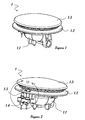
- Figs. 1 and 2 are perspective views of the burner according to the invention
- Fig. 3 is the detailed view of the burner (1) according to the invention showing igniter (1.4) and flame holder (1.5) sections thereof
- Fig. 4 is the front detailed view of the burner (1) according to the invention showing igniter (1.4) and flame holder (1.5) sections thereof
- Fig. 5 is the exploded view of the burner (1) according to the invention
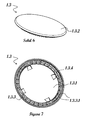
- Fig. 6 is the perspective view showing the upper part of the cap (1.3) in the burner (1) according to the invention
- Fig. 7 is the perspective view showing the lower part of the cap (1.3) in the burner (1) according to the invention
- Figs. 8 and 13 are the top views of the cap (1.3) in the burner (1) according to the invention
- Fig. 1 and 2 are perspective views of the burner according to the invention
- Fig. 3 is the detailed view of the burner (1) according to the invention showing igniter (1.4) and flame holder (1.5) sections thereof
- Fig. 4 is the front detailed view of the burner (1) according to
- FIG. 9 is the top view of the base (1.2) provided in the burner (1) according to the invention
- Fig. 10 is the perspective view of the base (1.2) provided in the burner (1) according to the invention
- Fig. 11 is the detailed view of the base (1.2) provided in the burner (1) according to the invention
- Fig. 12 is the cross-sectional view of the burner (1) according to the invention
- Fig. 14 is the cross-sectional view of the cap (1.3) provided in the burner (1) according to the invention
- Fig. 15 is the detailed view of the cap (1.3) provided in the burner (1) according to the invention.
- the burner (1) consists of a pool (1.1), a base (1.2) and a cap (1.3).
- said cap (1.3) can be made of aluminum via injection moulding method, brass via hot forging method, or of any one of the materials including glass, porcelain, ceramics, which are resistant to heat and thermal shock, as a single piece, alternatively it can be made of brass or aluminum material, and then applied teflon or ceramic coating thereon for providing thermal resistance and for obtaining different colors, said cap comprising a convex upper surface (1.3.2), at least two C-shaped cavities (1.3.4) radially scattered around its center in order for it to be easily mounted on said base (1.2), and a convex lower surface (1.3.1) provided with a port ring (1.3.3) having the ports (1.3.3.1) through which the flame exists.
- the pool (1.1) is mounted on the griddle and is provided thereon with an injector (1.6), a flame holder (1.5) and an igniter (1.4).
- the base (1.2) is positioned on said pool (1.1). This positioning is provided due to the fact that the vertical ridges are mounted on the walls of the pool (1.1), in the lower part of said base (1.2).
- the cap (1.3) is positioned on said base (1.2). As seen in detailed views of the burner (1) given in Figs. 4 and 5 , the igniter (1.4) is positioned close to the port ring (1.3.3).
- first burning is achieved by emitting sparks (1.4.1) to the ports (1.3.3.1) provided on the port ring (1.3.3) at certain intervals, and then burning takes place in all ports of the burner (1) due to flame switch to the consecutive ports.
- the igniter (1.4) emits spark (1.4.1) towards the ports at certain intervals in a horizontal manner, and thus burning is achieved easily.
- the upper surface (1.3.2) of the cap (1.3) according to the invention is designed in convex form.
- thermal efficiency of the burner (1) has been increased by making the burner (1) closer to the cooking pot, e.g. pan, sauce pan, etc., put thereon.
- a port ring (1.3.3) is provided on which the ports (1.3.3.1), through which the flame exits, are provided, as well as at least two C-shaped cavities (1.3.4) radially scattered around its center in order for it to be easily mounted on the base (1.2).
- Said at least two C-shaped cavities (1.3.4) are located in at least two ridges (1.2.3) provided on the base (1.2) seen in Fig. 10 .
- At least two ridges (1.2.3) provided on said base (1.2) and radially scattered around the center thereof are formed such that a certain ridge outer length (1.2.3.1) is widened to a certain ridge inner length (1.2.3.2) towards the burner (1) center, so as to allow it to be engaged in at least two C-shaped cavities (1.3.4) provided on the cap (1.3).
- the cap (1.3) in order for at least two C-shaped cavities (1.3.4) on the cap (1.3) to fit in at least two ridges (1.2.3) radially scattered around the center of the base (1.2), it is designed such that it will be widened to a certain cavity inner length (1.3.4.2) from a certain cavity outer length (1.3.4.1) towards the cap (1.3) center.
- the cap (1.3) can be readily positioned on the base (1.2).
- the skirt portion (1.2.5) is provided with an igniter bearing (1.2.1) and a flame holder bearing (1.2.2).
- Fig. 12 shows the cross-sectional view of the burner (1) when the base (1.2) is mounted on the pool (1.1) and the cap (1.3) according to the invention is mounted on the base (1.2).
- the route of the gas in said burner (1) is tried to be described with vectors.
- the gas coming from gas inlet (1.1.1) passes through the injector (1.6), thereby passing through the circular channel (1.2.4) of the base (1.2) with venturi effect. Having passed through the circular channel (1.2.4), the gas reaches to ports (1.3.3.1) by hitting the lower surface (1.3.1) of the cap (1.3) in the burner (1) according to the invention.
- the lower surface (1.3.1) of the cap (1.3) is also designed in convex form in order to facilitate distribution of the gas to the ports (1.3.3.1) by hitting the lower surface (1.3.1) of the cap (1.3).
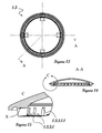
- Fig. 13 is the top view of the cap (1.3) in the burner (1) according to the invention.
- Fig. 14 is A-A cross-sectional view of the cap (1.3) according to the invention. As seen in cross-sectional view, both of the lower surface (1.3.1) and the upper surface (1.3.2) of the cap (1.3) are designed in convex form.
- Fig. 15, on the other hand gives B detail view obtained from the cross-sectional view of the cap (1.3) in Fig. 14 .
- ports' (1.3.3.1) bottom (1.3.3.1.1) provided in the lower surface (1.3.1) of the cap (1.3) according to the invention is designed such that the bottom angle (X) will be inclined downwards at a certain angle.
- This bottom angle (X) may preferably have a value between 2 0 and 8 0 .
- 65-70% thermal efficiency is achieved, which is quite good when it comes to burners.
- the invention is suitable for use in small burners, middle burners, big burners, and turbo burners, all of which have different power (kW) values, provided in any domestic cooker or oven. Moreover, different production methods performed without drifting away the design provided by the present invention and the use of coating techniques and materials with different colors and characteristics do not mean exceeding the scope of the invention.
Landscapes
- Engineering & Computer Science (AREA)
- Chemical & Material Sciences (AREA)
- Combustion & Propulsion (AREA)
- Mechanical Engineering (AREA)
- General Engineering & Computer Science (AREA)
- Gas Burners (AREA)
Applications Claiming Priority (1)
| Application Number | Priority Date | Filing Date | Title |
|---|---|---|---|
| TR201213374 | 2012-11-20 |
Publications (1)
| Publication Number | Publication Date |
|---|---|
| EP2733422A1 true EP2733422A1 (de) | 2014-05-21 |
Family
ID=48143508
Family Applications (1)
| Application Number | Title | Priority Date | Filing Date |
|---|---|---|---|
| EP13164653.1A Withdrawn EP2733422A1 (de) | 2012-11-20 | 2013-04-22 | Brenner für Haushalt-Kochgeräte |
Country Status (1)
| Country | Link |
|---|---|
| EP (1) | EP2733422A1 (de) |
Cited By (4)
| Publication number | Priority date | Publication date | Assignee | Title |
|---|---|---|---|---|
| WO2016145745A1 (zh) * | 2015-03-13 | 2016-09-22 | 广东美的厨房电器制造有限公司 | 燃烧器 |
| CN108006649A (zh) * | 2017-12-29 | 2018-05-08 | 华帝股份有限公司 | 一种带玻璃的复合结构燃烧器 |
| WO2021045697A1 (en) * | 2019-07-10 | 2021-03-11 | Femas Metal San. Ve Tic. A.S. | A burner assembly for gas cooker device and production method thereof |
| WO2025225095A1 (ja) * | 2024-04-26 | 2025-10-30 | リンナイ株式会社 | 加熱調理器用バーナ並びに加熱調理器 |
Citations (7)
| Publication number | Priority date | Publication date | Assignee | Title |
|---|---|---|---|---|
| JPS6011012A (ja) * | 1983-06-30 | 1985-01-21 | Matsushita Electric Works Ltd | ガスバ−ナ |
| US5468145A (en) * | 1994-01-24 | 1995-11-21 | Lincoln Brass Works, Inc. | Sealed gas burner assembly |
| US5924860A (en) * | 1997-08-28 | 1999-07-20 | Harper-Wyman Company | Thickwall gas burner assembly |
| US6146132A (en) * | 1999-08-14 | 2000-11-14 | Harneit; Uwe | Gas burner for outdoor cooking |
| WO2004000020A1 (de) | 2002-06-24 | 2003-12-31 | Bayer Cropscience Aktiengesellschaft | Fungizide wirkstoffkombinationen |
| EP1703203A1 (de) | 2005-02-17 | 2006-09-20 | Electrolux Home Products Corporation N.V. | Gasbrenner |
| TR201110814A2 (tr) * | 2011-10-31 | 2012-08-22 | Turaş Gaz Armatürleri̇ San. Ve Ti̇c. A.Ş. | Gaz yakıcısı. |
-
2013
- 2013-04-22 EP EP13164653.1A patent/EP2733422A1/de not_active Withdrawn
Patent Citations (8)
| Publication number | Priority date | Publication date | Assignee | Title |
|---|---|---|---|---|
| JPS6011012A (ja) * | 1983-06-30 | 1985-01-21 | Matsushita Electric Works Ltd | ガスバ−ナ |
| US5468145A (en) * | 1994-01-24 | 1995-11-21 | Lincoln Brass Works, Inc. | Sealed gas burner assembly |
| US5924860A (en) * | 1997-08-28 | 1999-07-20 | Harper-Wyman Company | Thickwall gas burner assembly |
| US6146132A (en) * | 1999-08-14 | 2000-11-14 | Harneit; Uwe | Gas burner for outdoor cooking |
| WO2004000020A1 (de) | 2002-06-24 | 2003-12-31 | Bayer Cropscience Aktiengesellschaft | Fungizide wirkstoffkombinationen |
| EP1703203A1 (de) | 2005-02-17 | 2006-09-20 | Electrolux Home Products Corporation N.V. | Gasbrenner |
| TR201110814A2 (tr) * | 2011-10-31 | 2012-08-22 | Turaş Gaz Armatürleri̇ San. Ve Ti̇c. A.Ş. | Gaz yakıcısı. |
| EP2587144A2 (de) * | 2011-10-31 | 2013-05-01 | Turas Gaz Armatürleri Sanayi. Ve Ticaret A.S. | Gasbrenner |
Cited By (5)
| Publication number | Priority date | Publication date | Assignee | Title |
|---|---|---|---|---|
| WO2016145745A1 (zh) * | 2015-03-13 | 2016-09-22 | 广东美的厨房电器制造有限公司 | 燃烧器 |
| US10465903B2 (en) | 2015-03-13 | 2019-11-05 | Guangdong Midea Kitchen Appliances Manufacturing Co., Ltd. | Burner |
| CN108006649A (zh) * | 2017-12-29 | 2018-05-08 | 华帝股份有限公司 | 一种带玻璃的复合结构燃烧器 |
| WO2021045697A1 (en) * | 2019-07-10 | 2021-03-11 | Femas Metal San. Ve Tic. A.S. | A burner assembly for gas cooker device and production method thereof |
| WO2025225095A1 (ja) * | 2024-04-26 | 2025-10-30 | リンナイ株式会社 | 加熱調理器用バーナ並びに加熱調理器 |
Similar Documents
| Publication | Publication Date | Title |
|---|---|---|
| US10816215B2 (en) | Diffusion cap burner for gas cooking appliance | |
| US7661954B2 (en) | Gas burner | |
| AU2001262598B2 (en) | Burner with internal separator | |
| US7694671B2 (en) | Flame focusing ring for stovetop gas burner and universal wok support | |
| US20160084504A1 (en) | Integrated cooktop assembly | |
| CN101120209B (zh) | 燃气炉 | |
| CN105723153A (zh) | 燃气燃烧器、燃气灶具以及燃气烹饪器具 | |
| US20230314006A1 (en) | Pan support, gas hob and method for producing a pan support | |
| KR20160064017A (ko) | 가스 조리 기기, 특히, 가스 오븐 | |
| CN106594721B (zh) | 燃烧器和燃气灶具 | |
| EP2587144A2 (de) | Gasbrenner | |
| CN108006642B (zh) | 一种燃气灶具的燃烧器火盖 | |
| US7650882B2 (en) | Pot supports and burner systems including same | |
| EP3165828A1 (de) | Gasbrenner für kochfeld | |
| US20160255995A1 (en) | Stove-top barbecue | |
| JP3790184B2 (ja) | ガラストップコンロ | |
| US20120103320A1 (en) | Set of base and stove burner spreading cap, stove burner spreading cap and stove | |
| ITTO940261A1 (it) | Piano di cottura domestico, con bruciatori di gas ad assetto variabile | |
| KR20070001150U (ko) | 솥 | |
| JP2020153538A (ja) | バーナーキャップ、コンロバーナー、及び加熱調理器 | |
| CN220158109U (zh) | 一种烤网结构及烧烤炉 | |
| CN213656746U (zh) | 火盖和具有该火盖的燃烧器 | |
| CN111853791B (zh) | 灶具火盖 | |
| KR200199932Y1 (ko) | 세라믹 저면판이 설치된 음식물 조리용기 | |
| KR101166531B1 (ko) | 연료 절약형 조리용기 |
Legal Events
| Date | Code | Title | Description |
|---|---|---|---|
| PUAI | Public reference made under article 153(3) epc to a published international application that has entered the european phase |
Free format text: ORIGINAL CODE: 0009012 |
|
| 17P | Request for examination filed |
Effective date: 20130422 |
|
| AK | Designated contracting states |
Kind code of ref document: A1 Designated state(s): AL AT BE BG CH CY CZ DE DK EE ES FI FR GB GR HR HU IE IS IT LI LT LU LV MC MK MT NL NO PL PT RO RS SE SI SK SM TR |
|
| AX | Request for extension of the european patent |
Extension state: BA ME |
|
| R17P | Request for examination filed (corrected) |
Effective date: 20140620 |
|
| RBV | Designated contracting states (corrected) |
Designated state(s): AL AT BE BG CH CY CZ DE DK EE ES FI FR GB GR HR HU IE IS IT LI LT LU LV MC MK MT NL NO PL PT RO RS SE SI SK SM TR |
|
| STAA | Information on the status of an ep patent application or granted ep patent |
Free format text: STATUS: THE APPLICATION IS DEEMED TO BE WITHDRAWN |
|
| 18D | Application deemed to be withdrawn |
Effective date: 20141122 |