EP2735656A1 - Chaîne cinématique d'un véhicule - Google Patents
Chaîne cinématique d'un véhicule Download PDFInfo
- Publication number
- EP2735656A1 EP2735656A1 EP13191525.8A EP13191525A EP2735656A1 EP 2735656 A1 EP2735656 A1 EP 2735656A1 EP 13191525 A EP13191525 A EP 13191525A EP 2735656 A1 EP2735656 A1 EP 2735656A1
- Authority
- EP
- European Patent Office
- Prior art keywords
- pump
- accumulator
- drive train
- hydraulic pump
- line
- Prior art date
- Legal status (The legal status is an assumption and is not a legal conclusion. Google has not performed a legal analysis and makes no representation as to the accuracy of the status listed.)
- Granted
Links
Images


Classifications
-
- F—MECHANICAL ENGINEERING; LIGHTING; HEATING; WEAPONS; BLASTING
- F15—FLUID-PRESSURE ACTUATORS; HYDRAULICS OR PNEUMATICS IN GENERAL
- F15B—SYSTEMS ACTING BY MEANS OF FLUIDS IN GENERAL; FLUID-PRESSURE ACTUATORS, e.g. SERVOMOTORS; DETAILS OF FLUID-PRESSURE SYSTEMS, NOT OTHERWISE PROVIDED FOR
- F15B1/00—Installations or systems with accumulators; Supply reservoir or sump assemblies
- F15B1/02—Installations or systems with accumulators
- F15B1/024—Installations or systems with accumulators used as a supplementary power source, e.g. to store energy in idle periods to balance pump load
-
- B—PERFORMING OPERATIONS; TRANSPORTING
- B60—VEHICLES IN GENERAL
- B60K—ARRANGEMENT OR MOUNTING OF PROPULSION UNITS OR OF TRANSMISSIONS IN VEHICLES; ARRANGEMENT OR MOUNTING OF PLURAL DIVERSE PRIME-MOVERS IN VEHICLES; AUXILIARY DRIVES FOR VEHICLES; INSTRUMENTATION OR DASHBOARDS FOR VEHICLES; ARRANGEMENTS IN CONNECTION WITH COOLING, AIR INTAKE, GAS EXHAUST OR FUEL SUPPLY OF PROPULSION UNITS IN VEHICLES
- B60K6/00—Arrangement or mounting of plural diverse prime-movers for mutual or common propulsion, e.g. hybrid propulsion systems comprising electric motors and internal combustion engines
- B60K6/08—Prime-movers comprising combustion engines and mechanical or fluid energy storing means
- B60K6/12—Prime-movers comprising combustion engines and mechanical or fluid energy storing means by means of a chargeable fluidic accumulator
-
- B—PERFORMING OPERATIONS; TRANSPORTING
- B60—VEHICLES IN GENERAL
- B60K—ARRANGEMENT OR MOUNTING OF PROPULSION UNITS OR OF TRANSMISSIONS IN VEHICLES; ARRANGEMENT OR MOUNTING OF PLURAL DIVERSE PRIME-MOVERS IN VEHICLES; AUXILIARY DRIVES FOR VEHICLES; INSTRUMENTATION OR DASHBOARDS FOR VEHICLES; ARRANGEMENTS IN CONNECTION WITH COOLING, AIR INTAKE, GAS EXHAUST OR FUEL SUPPLY OF PROPULSION UNITS IN VEHICLES
- B60K6/00—Arrangement or mounting of plural diverse prime-movers for mutual or common propulsion, e.g. hybrid propulsion systems comprising electric motors and internal combustion engines
- B60K6/20—Arrangement or mounting of plural diverse prime-movers for mutual or common propulsion, e.g. hybrid propulsion systems comprising electric motors and internal combustion engines the prime-movers consisting of electric motors and internal combustion engines, e.g. HEVs
- B60K6/42—Arrangement or mounting of plural diverse prime-movers for mutual or common propulsion, e.g. hybrid propulsion systems comprising electric motors and internal combustion engines the prime-movers consisting of electric motors and internal combustion engines, e.g. HEVs characterised by the architecture of the hybrid electric vehicle
- B60K6/46—Series type
-
- B—PERFORMING OPERATIONS; TRANSPORTING
- B60—VEHICLES IN GENERAL
- B60W—CONJOINT CONTROL OF VEHICLE SUB-UNITS OF DIFFERENT TYPE OR DIFFERENT FUNCTION; CONTROL SYSTEMS SPECIALLY ADAPTED FOR HYBRID VEHICLES; ROAD VEHICLE DRIVE CONTROL SYSTEMS FOR PURPOSES NOT RELATED TO THE CONTROL OF A PARTICULAR SUB-UNIT
- B60W10/00—Conjoint control of vehicle sub-units of different type or different function
- B60W10/30—Conjoint control of vehicle sub-units of different type or different function including control of auxiliary equipment, e.g. air-conditioning compressors or oil pumps
-
- E—FIXED CONSTRUCTIONS
- E02—HYDRAULIC ENGINEERING; FOUNDATIONS; SOIL SHIFTING
- E02F—DREDGING; SOIL-SHIFTING
- E02F9/00—Component parts of dredgers or soil-shifting machines, not restricted to one of the kinds covered by groups E02F3/00 - E02F7/00
- E02F9/20—Drives; Control devices
- E02F9/2058—Electric or electro-mechanical or mechanical control devices of vehicle sub-units
- E02F9/2062—Control of propulsion units
- E02F9/2066—Control of propulsion units of the type combustion engines
-
- E—FIXED CONSTRUCTIONS
- E02—HYDRAULIC ENGINEERING; FOUNDATIONS; SOIL SHIFTING
- E02F—DREDGING; SOIL-SHIFTING
- E02F9/00—Component parts of dredgers or soil-shifting machines, not restricted to one of the kinds covered by groups E02F3/00 - E02F7/00
- E02F9/20—Drives; Control devices
- E02F9/22—Hydraulic or pneumatic drives
- E02F9/2217—Hydraulic or pneumatic drives with energy recovery arrangements, e.g. using accumulators, flywheels
-
- E—FIXED CONSTRUCTIONS
- E02—HYDRAULIC ENGINEERING; FOUNDATIONS; SOIL SHIFTING
- E02F—DREDGING; SOIL-SHIFTING
- E02F9/00—Component parts of dredgers or soil-shifting machines, not restricted to one of the kinds covered by groups E02F3/00 - E02F7/00
- E02F9/20—Drives; Control devices
- E02F9/22—Hydraulic or pneumatic drives
- E02F9/2278—Hydraulic circuits
- E02F9/2292—Systems with two or more pumps
-
- F—MECHANICAL ENGINEERING; LIGHTING; HEATING; WEAPONS; BLASTING
- F02—COMBUSTION ENGINES; HOT-GAS OR COMBUSTION-PRODUCT ENGINE PLANTS
- F02N—STARTING OF COMBUSTION ENGINES; STARTING AIDS FOR SUCH ENGINES, NOT OTHERWISE PROVIDED FOR
- F02N7/00—Starting apparatus having fluid-driven auxiliary engines or apparatus
-
- F—MECHANICAL ENGINEERING; LIGHTING; HEATING; WEAPONS; BLASTING
- F02—COMBUSTION ENGINES; HOT-GAS OR COMBUSTION-PRODUCT ENGINE PLANTS
- F02N—STARTING OF COMBUSTION ENGINES; STARTING AIDS FOR SUCH ENGINES, NOT OTHERWISE PROVIDED FOR
- F02N11/00—Starting of engines by means of electric motors
- F02N11/08—Circuits specially adapted for starting of engines
- F02N11/0814—Circuits specially adapted for starting of engines comprising means for controlling automatic idle-start-stop
-
- Y—GENERAL TAGGING OF NEW TECHNOLOGICAL DEVELOPMENTS; GENERAL TAGGING OF CROSS-SECTIONAL TECHNOLOGIES SPANNING OVER SEVERAL SECTIONS OF THE IPC; TECHNICAL SUBJECTS COVERED BY FORMER USPC CROSS-REFERENCE ART COLLECTIONS [XRACs] AND DIGESTS
- Y02—TECHNOLOGIES OR APPLICATIONS FOR MITIGATION OR ADAPTATION AGAINST CLIMATE CHANGE
- Y02T—CLIMATE CHANGE MITIGATION TECHNOLOGIES RELATED TO TRANSPORTATION
- Y02T10/00—Road transport of goods or passengers
- Y02T10/60—Other road transportation technologies with climate change mitigation effect
- Y02T10/62—Hybrid vehicles
Definitions
- the invention relates to a drive train of a vehicle, in particular a mobile work machine, with an internal combustion engine and driven by the internal combustion engine traction drive and driven by the engine working hydraulic system, wherein the working hydraulic system comprises at least one driven by the internal combustion engine hydraulic pump which is operable as a pump and motor wherein the hydraulic pump sucks pressure medium from a reservoir in pumping operation with a suction side and delivers it to a delivery line leading to the working hydraulic system, and wherein the hydraulic pump is in engine operation in which the hydraulic pump is designed as a hydraulic starter of a start-stop function for starting the internal combustion engine, on the suction side pressure medium from a pressure fluid accumulator can be supplied, wherein the guided to the working hydraulic system delivery line of the hydraulic pump to the pressure medium storage led dacasleitun g is connected.
- the working hydraulic system comprises at least one driven by the internal combustion engine hydraulic pump which is operable as a pump and motor wherein the hydraulic pump sucks pressure medium from a reservoir in pumping operation with a suction side and
- Mobile self-propelled machines especially industrial trucks, agricultural machinery, forestry machinery and construction equipment, such as excavators, wheeled and telescopic loaders, tractors, combine harvester, forage harvester, sugar beet or potato harvester, have a drive train with an internal combustion engine, a traction drive and a working hydraulic system for the working functions of Working machine drives.
- To supply the working hydraulic system with pressure medium at least one of the internal combustion engine driven hydraulic pump is provided.
- the internal combustion engine is operated at a lower idling speed. Such idling operation takes place during work breaks or during work stoppages.
- electric motor driven starters are usually used with which the start of the parked internal combustion engine, the speed required for self-running of the engine is generated with an electric starter motor, which is connected via a transmission to the crankshaft of the engine ,
- the transmission is usually formed by a pinion on the output shaft of the electric starter motor and a ring gear on the crankshaft of the internal combustion engine and has a high gear ratio, so that a high-speed and small-sized electric starter motor can be used.
- hydrostatic engines are used as hydraulic starter of the engine for a start-stop function, which are drivingly connected to the crankshaft of the engine and operated with pressure fluid from a pressure fluid accumulator during a starting operation of the internal combustion engine.
- a powertrain is known in which, in addition to the hydraulic pump of the working hydraulic system, a further hydraulic motor is provided as a starter of the internal combustion engine for a start-stop function of the internal combustion engine. Since such an additional hydraulic motor is dragged in the drive train during normal operation of the current internal combustion engine, losses occur that reduce the overall efficiency of the working machine.
- Upstream of the charging valve is connected to the delivery line to a pressure medium storage led connecting line connected, in which an electrically operated shut-off valve is arranged.
- the electrically operated shut-off valve is driven to load the accumulator in a flow position and actuated upon reaching a certain accumulator charging pressure, which is monitored by a pressure sensor, back to the blocking position to shut off the accumulator.
- an electrically operated shut-off valve in the connecting line connecting the delivery line with the accumulator causes high construction costs and space requirements.
- charging of the accumulator may lead to inadmissibly high accumulator charging pressures.
- the present invention has for its object to provide a drive train of the type mentioned available, which is improved in terms of construction costs and space requirements for a charging circuit of the accumulator and has an effective protection of the accumulator charging pressure.
- a throttle device in particular a diaphragm or throttle arranged.
- designed as a throttle or orifice throttle device in the guided to the pressure medium accumulator line can be limited in a simple way, the charge flow in the accumulator.
- a charge valve throttling the delivery line for loading the pressure medium reservoir is arranged in the delivery line of the hydraulic pump guided to the working hydraulic system, and the connection line is connected to the delivery line upstream of the charge valve.
- the delivery line can be throttled even in operating conditions in which no consumer of the working hydraulic system is actuated, to allow loading of the accumulator by the funded by the hydraulic pump in pump flow.
- the charging valve is designed according to an embodiment of the invention as a retarder valve, which is actuated in the braking operation of the vehicle in a throttling the delivery line throttle position.
- a retarder valve can be braked by throttling the delivery line of the hydraulic pump in a braking operation of the vehicle via the engine and its drag torque.
- throttling Retarderventil can also be done easily energy recovery and the pressure fluid reservoir are loaded so that the kinetic energy of the vehicle during a braking operation is used to load the accumulator.
- connection of the accumulator with the suction side of the hydraulic pump by means of an electrically actuated control valve is controllable.
- an electrically actuable control valve can easily the Engine operation of the hydraulic pump can be controlled at a starting operation of the parked engine.
- the control valve is preferably arranged in a branch line, which is guided from the connecting line between the check valve and the pressure medium accumulator to a suction line of the hydraulic pump, which is guided from the container to the suction side of the hydraulic pump.
- a blocking in the direction of the container shut-off valve, in particular a blocking towards the container check valve is arranged, can easily in engine operation of the hydraulic pump, a discharge of the pressure medium from the pressure fluid reservoir into the container be avoided and in pump operation of the hydraulic pump suction of pressure medium from the container can be achieved.
- connection line between the check valve and the accumulator is assigned a pressure sensor, the charging process of the accumulator and the connection to the control valve of the unloading operation of the accumulator can be controlled in a simple manner in conjunction with a charging valve controlling electronic control device.
- the hydraulic pump is provided for supplying a hydraulic steering device and the delivery side of the hydraulic pump is assigned a priority valve for the preferred supply of the steering hydraulics, to the output side, the delivery line of the hydraulic system is connected.
- the hydraulic pump can be made possible with such a priority valve in a simple manner, the preferred supply of a steering device, by the connection of the connecting line of the accumulator to the guided from the priority valve to the working hydraulic system delivery line loading the accumulator no influence on the prioritization and priority of the steering device Has.
- the drive train is provided with a driven by the engine feed pump, which serves as a pump and motor is operable, wherein the feed pump sucks in the pump operation with a suction side pressure medium from a container and conveys into a fed to a feed pressure supply line, and wherein the feed pump in engine operation on the suction side pressure medium from the accumulator is supplied.
- a feed pump which can also be operated as a motor with pressure fluid from the pressure fluid accumulator, the torque for starting the internal combustion engine can be increased in a simple manner during a starting process.
- a booster drive can be achieved and an additional torque can be introduced into the drive train, with the running internal combustion engine during an acceleration process or while driving the vehicle while driving stationary at a target speed and in the operation of the working hydraulic system can be supported.
- the hydrostatic booster drive formed by the feed pump can be used to downsize the internal combustion engine.
- connection of the accumulator with the suction side of the feed pump by means of another electrically actuated control valve is controllable.
- the further control valve is arranged in a branch line, which is guided by the connecting line between the check valve and the accumulator to a suction line of the feed pump, which is guided from the container to the suction side of the feed pump.
- a blocking in the direction of the container shut-off valve in particular a blocking towards the container check valve is arranged, can easily in engine operation of the feed pump, a discharge of the pressure medium the accumulator in the container can be avoided and in the pump operation of the feed pump, a suction of pressure medium from the container can be achieved.
- the hydraulic pump of the working hydraulic system and the feed pump to a common intake passage which connects the suction side of the hydraulic pump and the suction side of the feed pump to the container and in which a blocking direction towards the container check valve, in particular one towards the container locking check valve, is arranged, wherein the pressure fluid accumulator is connected by means of a common electrically actuated control valve with the common intake port of the hydraulic pump and the feed pump.
- the common control valve is arranged in a branch line, which is guided by the connecting line between the check valve and the accumulator to the common intake port of the hydraulic pump and the feed pump.
- the operated as a pump and motor feed pump can be formed in this case in addition to the operated in engine operation hydraulic pump of the hydraulic power system as a hydraulic starter for starting the engine.
- the feed pump which can be operated as a motor can be designed as a booster drive for the delivery of torque into the drive train driven by the running internal combustion engine.
- the hydraulic pump of the working hydraulic system can be designed as a fixed displacement pump with a fixed displacement volume or as a variable displacement pump with an adjustable displacement.
- the hydraulic pump of the working hydraulic system is expediently designed as an axial piston machine, preferably as an axial piston machine in a swash plate design, or as a radial piston machine or as a gear machine.
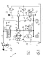
- FIG. 1 is an inventive drive train 1 of a mobile work machine, not shown, for example, a truck or a construction or agricultural machine, shown in a schematic diagram.
- the drive train 1 consists of an internal combustion engine 2, for example a diesel engine, a traction drive 3 of the vehicle driven by the internal combustion engine 2 and a working hydraulic system 4 driven by the internal combustion engine 2.
- an internal combustion engine 2 for example a diesel engine
- a traction drive 3 of the vehicle driven by the internal combustion engine 2 and a working hydraulic system 4 driven by the internal combustion engine 2.
- the traction drive 3 is formed in the illustrated embodiment as a hydrostatic drive, which consists of an adjustable in the delivery volume drive pump 5, which is in drive connection to the drive with an output shaft 6 of the engine 2.
- the drive pump 5 is connected to one or more in the intake volume fixed or adjustable, not shown hydromotors in a closed circuit in connection, which are in a manner not shown in operative connection with the driven wheels of the machine.
- the traction drive 3 may alternatively be formed as an electric traction drive with an electric generator driven by the internal combustion engine 2 and one or more electric traction motors.
- a mechanical travel drive with a mechanical transmission such as a multi-step transmission or a power split transmission or a torque converter transmission, can be provided.
- the working hydraulic system 4 includes working functions of the working machine, for example, in a truck, a working hydraulics for operating a lifting device on a mast, or in a trained example as an excavator construction machine, the working functions of trained by a blade work equipment.
- the working hydraulic system 4 comprises in the illustrated embodiment at least one operated in the open circuit hydraulic pump 7, which is in driving connection with the output shaft 6 of the internal combustion engine 2 for driving.
- the hydraulic pump 7 of the working hydraulic system 4 is in the embodiment of FIG. 1 designed as a constant displacement pump with a constant displacement volume.
- the hydraulic pump 7 is the input side with the suction side by means of a suction line 8 with a container 9 in connection.
- An output side connected to the delivery side of the hydraulic pump 7 in communication line 10 is connected to a control valve means, not shown, by means of which the hydraulic consumers of the working hydraulic system 4, not shown, are controllable.
- the control valve device preferably comprises one or more directional control valves for actuating the consumers.
- a priority valve 12 is further shown, with which the preferred supply of a powered by the hydraulic pump 7 consumer, such as a hydraulic steering device, can be ensured.
- the priority valve 12 is connected on the input side to the delivery side of the hydraulic pump 7 and is connected on the output side to the delivery line 10 routed to the working hydraulic system 4 and to a delivery line 13 routed to the steering device.
- the priority valve 12 is controlled by a spring 14 and the pending in a load pressure line 15 load pressure of the steering device.
- the drive train 1 further comprises a feed pump 20, which is connected to the drive with the output shaft 6 in connection.
- the feed pump 20 is formed as a constant displacement pump with a constant displacement volume, which is operated in the open circuit.
- the feed pump 20 communicates with the suction side via a suction line 21 to the container 9 and conveys into a feed pressure line 22 connected to the feed side, to which the corresponding consumers of a feed circuit 23 are connected, for example an adjusting device for adjusting the displacement volume of the drive pump 5
- a pressure limiting device 24 for example, a pressure relief valve associated with.
- the hydraulic pump 7 of the working hydraulic system 4 is designed as Zwequadrantentriebwerk, which is operable at the same direction of rotation and the same flow direction of the pressure medium as a pump and motor.
- the hydraulic pump 7 sucks pressure medium from the container 9 via the suction line 8 and delivers the pressure medium via the priority valve 12 into the delivery line 10 of the working hydraulic system 4 or the delivery line 13 of the steering device.
- the hydraulic pump 7 is driven on the suction side with pressure medium from a pressure medium reservoir 25.
- the accumulator 25 is connected for charging with pressure medium to the guided to the working hydraulic system 4 conveying line 10 of the hydraulic pump 7 by means of a connecting line 26.
- an electrically actuated charging valve 27 is arranged, which is actuated at a control in a throttling the delivery line 10 throttle position for damming a pressure.
- the charging valve 27 is preferably designed as a retarder valve 28, which in the braking operation of the vehicle in a Throttle position is actuated to decelerate by damming a pressure in the feed line 10 and the drag torque of the engine 2, the vehicle.
- the connecting line 26 is in this case connected upstream of the charging valve 27 and thus between the charging valve 27 and the priority valve 12 to the delivery line 10.
- a self-acting and pressure-dependent in the direction of the pressure medium reservoir 25 opening check valve 30 is arranged, which is preferably designed as in the direction of the accumulator 25 opening check valve 31. Furthermore, the connecting line 26 between the check valve 30 and the accumulator 25, a pressure relief valve 32 to protect the pressure in the accumulator 25 is assigned.
- a throttle device 33 is further arranged to limit the loading volume flow of the accumulator 25, which may be designed as a diaphragm or throttle. As shown, the throttle device 33 can be arranged upstream of the shut-off valve 30 or alternatively downstream of the shut-off valve 30.
- the connecting line 26 between the check valve 30 and the accumulator 25 is further associated with a pressure sensor 34.
- the pressure sensor 34 is used to monitor the boost pressure and thus the state of charge of the accumulator 25.
- the connection of the accumulator 25 with the suction side of the hydraulic pump 7 for the engine operation of the hydraulic pump 7 is controllable by means of an electrically actuated control valve 35.
- the control valve 35 has a blocking position 35a and a flow-through position 35b, wherein the blocking position 35a is preferably designed leak-tight with a blocking in the direction of the hydraulic pump 7 check valve.
- the control valve 35 is arranged in a branch line 36, which is guided by the connecting line 26 between the check valve 30 and the accumulator 25 to the guided to the suction side of the hydraulic pump 7 suction line 8.
- check valve 37 In the suction line 8 of the hydraulic pump 7 a blocking in the direction of the container 9 check valve 37 is arranged, which is preferably designed as a blocking in the direction of the container check valve 38.
- An electronic control device 40 is connected to the input side of the pressure sensor 34 and serves to control the charging valve 27 and the control valve 35th
- FIG. 2 a second embodiment of the invention is shown in which the operable as a pump and motor hydraulic pump 7 is designed to supply the working hydraulic system 4 and the steering device as a variable displacement with an adjustable displacement volume, for example, as axial piston machine in swash plate design.
- the feed pump 20 is the FIG. 2 designed as Zwequadrantentriebwerk, which is operable at the same direction of rotation and the same flow direction of the pressure medium as a pump and motor.
- the feed pump 20 draws with the connected to the suction side suction 21 pressure fluid from the container 9 and delivers into the feed pressure line 22 which is connected to the delivery side of the feed pump.
- the feed pump 20 is formed in addition to the hydraulic pump 7 as a hydraulic starter a start-stop function for starting the engine 2 and / or as a booster drive to support the current internal combustion engine 2, the feed pump. 7 driven on the suction side with pressure medium from the accumulator 25.
- control valve 45 To control the connection of the accumulator 25 with the suction side of the feed pump 20 for the motor operation of the feed pump 20, a further electrically actuated control valve 45 is provided.
- the control valve 45 has a blocking position 45a and a flow position 45b, wherein the blocking position 45a is preferably carried out leak-tight with a blocking in the direction of the feed pump 20 check valve.
- the further control valve 45 is arranged in a branch line 46, which is guided by the connecting line 26 between the check valve 30 and the accumulator 25 to the suction line 21 of the feed pump 20.
- the further control valve 45 can also be actuated by the electronic control device 40.
- a blocking in the direction of the container 9 check valve 47 is further arranged, which is preferably designed as a blocking in the direction of the container 9 check valve 48.
- FIG. 3 a development of a drive train 1 is shown, in which the hydraulic pump 7 and the feed pump 20 are each formed as Zwequadrantentriebwerke, which are operable as a pump and motor.
- the hydraulic pump 7 of the working hydraulic system 4 and the feed pump 20 have a common intake passage 50 connecting the suction side and thus the intake passage 8 of the hydraulic pump 7 and the suction side and thus the intake passage 21 of the charge pump 20 to the reservoir 9.
- a check valve 51 which closes in the direction of the container is arranged, which is preferably designed as a non-return valve 52 blocking the direction of the container.
- a common electrically actuated control valve 55 is provided.
- the control valve 55 has a blocking position 55a and a flow-through position 55b, wherein the blocking position 55a is preferably designed leakproof with a blocking in the direction of the intake passage 50 check valve.
- the control valve 55 is operable by the electronic control device 40.
- the common control valve 55 is arranged in a branch line 56, which is guided by the connecting line 26 between the check valve 30 and the accumulator 25 to the common intake passage 50 of the hydraulic pump 7 and the feed pump 20.
- the control valves 35, 45, 55 of the FIGS. 1 to 3 can be designed as switching valves or as proportional throttling in intermediate positions proportional valves.
- FIGS. 1 to 3 can the pressure fluid reservoir 25 via the throttle device 33 and the check valve 30 are charged in a simple manner upon actuation of a consumer of the working hydraulic system 4 with pressure medium, provided that the load pressure of the consumer exceeds the boost pressure of the pressure medium reservoir 25.
- the charging valve 27 in a throttle position of the accumulator 25 can be charged via the throttle device 33 and the check valve 30 in a simple manner in operating conditions in which the engine has 2 power reserves.
- Particular advantages arise when the charging valve 27 is designed as a retarder valve 28 and is operated in braking position of the vehicle in a throttle position, since the kinetic energy of the decelerating vehicle is used to load the accumulator 25 and thus can be an energy recovery.
- the drive pump 5 operates as a motor which drives the hydraulic pump 7 of the working hydraulic system 4, so that via the driven in the throttle position retarder valve 28 of the accumulator 25 can be charged with pressure medium.
- the hydraulic pump 7 thus promotes a flow for actuation of the consumers of the working hydraulic system 4 for controlled consumers of the working hydraulic system 4 and also serves to supply a flow for loading the accumulator 25.
- the hydraulic pump 7 on the primary side by the supplied from the engine 2 Power to be driven.
- the hydraulic pump 7 is driven to load the accumulator 25 with the recorded during deceleration of the vehicle in a braking operation kinetic energy of the vehicle.
- the hydraulic pump 7 of the working hydraulic system 4 is used in engine operation as a hydraulic starter for the parked engine 2 to achieve a start-stop function. This is at the FIG. 1 at sufficient pressure in the accumulator 25, the control valve 35 is actuated in the flow position 35b.
- the check valve 37 in the intake 8 prevents outflow of the pressure medium from the accumulator 25 in the container 9.
- the Control device 40 is provided in connection speed sensor, which is associated with the internal combustion engine 2 and the output shaft 6, the control valve 35 is actuated in the blocking position 35a to prevent further emptying of the accumulator 25.
- FIG. 3 can by the additional motor operation of the feed pump 20 in the flow position 55b of the control valve 55, wherein the hydraulic pump 7 and the feed pump 20 together form a hydraulic starter for the parked engine 2 to achieve a start-stop function, the torque to start the Increase internal combustion engine 2 in a simple manner.
- FIG. 2 can be increased to start the parked engine 2 in an engine operation of the hydraulic pump 7 by additional actuation of the further control valve 45 in the flow position 45b, the torque for starting the engine 2 by an additional engine operation of the feed pump 2.
- the two control valves 35, 45 possible to operate the feed pump 20 by operating the control valve 45 alone in the flow position 45b alone in engine operation to allow a booster drive by a motor operation of the feed pump 20, in which the feed pump 20 to the current Combustion engine 2 introduces an additional, the internal combustion engine 2 assisting torque in the drive train 1.
- the acceleration of the vehicle by the booster drive and the additional torque of the feed pump 20 can be supported by the accumulator 25 is connected via the control valve 45 at the beginning of the acceleration process of the vehicle with the feed pump 20.
- the duration of the boost process can be limited depending on the state of charge of the accumulator 25, which is detected by the pressure sensor 34. If at the end of the acceleration process of the vehicle in the accumulator 25 still sufficient pressure medium is present, the engine operation of the feed pump 20 can be maintained even at a steady drive of the vehicle with the target speed to use the moment from the booster drive of the feed pump 20.
Landscapes
- Engineering & Computer Science (AREA)
- General Engineering & Computer Science (AREA)
- Mechanical Engineering (AREA)
- Mining & Mineral Resources (AREA)
- Civil Engineering (AREA)
- Structural Engineering (AREA)
- Chemical & Material Sciences (AREA)
- Combustion & Propulsion (AREA)
- Transportation (AREA)
- Physics & Mathematics (AREA)
- Fluid Mechanics (AREA)
- Fluid-Pressure Circuits (AREA)
Applications Claiming Priority (1)
| Application Number | Priority Date | Filing Date | Title |
|---|---|---|---|
| DE102012111295.9A DE102012111295A1 (de) | 2012-11-22 | 2012-11-22 | Antriebsstrang eines Fahrzeugs |
Publications (2)
| Publication Number | Publication Date |
|---|---|
| EP2735656A1 true EP2735656A1 (fr) | 2014-05-28 |
| EP2735656B1 EP2735656B1 (fr) | 2021-12-29 |
Family
ID=49546280
Family Applications (1)
| Application Number | Title | Priority Date | Filing Date |
|---|---|---|---|
| EP13191525.8A Not-in-force EP2735656B1 (fr) | 2012-11-22 | 2013-11-05 | Chaîne cinématique d'un véhicule |
Country Status (4)
| Country | Link |
|---|---|
| US (1) | US9429170B2 (fr) |
| EP (1) | EP2735656B1 (fr) |
| CN (1) | CN103836009B (fr) |
| DE (1) | DE102012111295A1 (fr) |
Cited By (1)
| Publication number | Priority date | Publication date | Assignee | Title |
|---|---|---|---|---|
| WO2015200794A3 (fr) * | 2014-06-26 | 2016-04-14 | Parker-Hannifin Corporation | Système de puissance hydraulique pour démarrer des véhicules |
Families Citing this family (11)
| Publication number | Priority date | Publication date | Assignee | Title |
|---|---|---|---|---|
| DE102012111296A1 (de) * | 2012-11-22 | 2014-05-22 | Linde Hydraulics Gmbh & Co. Kg | Antriebsstrang eines Fahrzeugs, insbesondere einer mobilen Arbeitsmaschine |
| US20150368879A1 (en) * | 2014-06-24 | 2015-12-24 | Caterpillar Inc. | Combined Hydraulic Implement and Propulsion Circuit with Hybrid Energy Capture and Reuse |
| US9567986B2 (en) * | 2014-09-19 | 2017-02-14 | Caterpillar Inc. | Flow control for a hydraulic system |
| US20180003197A1 (en) * | 2015-01-26 | 2018-01-04 | Borgwarner Inc. | Accumulator and method of making and using the same |
| US9937919B2 (en) * | 2016-03-10 | 2018-04-10 | Ford Global Technologies, Llc | System and method for coupled and decoupled engine starting in a hybrid vehicle |
| DE102017118274A1 (de) * | 2017-08-10 | 2019-02-14 | Putzmeister Engineering Gmbh | Großmanipulator und hydraulische Schaltungsanordnung für einen Großmanipulator |
| PL237674B1 (pl) * | 2017-11-14 | 2021-05-17 | Politechnika Poznanska | Układ do oceny szczelności sekcji tłoczących pomp wtryskowych |
| DE102018108415A1 (de) * | 2018-04-10 | 2019-10-10 | Siempelkamp Maschinen- Und Anlagenbau Gmbh | Verfahren zum Betrieb eines hydraulischen Systems |
| US11821442B2 (en) | 2018-10-18 | 2023-11-21 | Volvo Construction Equipment Ab | Hydraulic energy handling system, a hydraulic parallel hybrid driveline and a working machine |
| CN115013210B (zh) * | 2022-06-15 | 2024-02-02 | 尤洛卡(山东)矿业科技有限公司 | 一种防爆柴油机启动控制系统 |
| US20260103873A1 (en) * | 2024-10-10 | 2026-04-16 | Deere & Company | Multifunctional transmission valve with integrated load brake function |
Citations (9)
| Publication number | Priority date | Publication date | Assignee | Title |
|---|---|---|---|---|
| JPS5923064A (ja) * | 1982-07-30 | 1984-02-06 | Nissan Motor Co Ltd | 車両のエンジン始動機構 |
| JP2006037820A (ja) * | 2004-07-26 | 2006-02-09 | Toyota Central Res & Dev Lab Inc | エンジン始動装置 |
| JP2007224737A (ja) * | 2006-02-21 | 2007-09-06 | Toyota Central Res & Dev Lab Inc | エンジン始動装置 |
| DE102009001602A1 (de) * | 2009-03-17 | 2010-09-23 | Zf Friedrichshafen Ag | Vorrichtung für einen Fahrzeugantriebsstrang mit einer Getriebeeinrichtung |
| WO2011140972A1 (fr) * | 2010-05-13 | 2011-11-17 | 济南谨恒节能技术有限公司 | Machine de déplacement à maniement hydraulique du type à économie d'énergie |
| US20120077632A1 (en) * | 2009-06-10 | 2012-03-29 | Czero Holding Company, Llc | Systems and methods for hybridization of a motor vehicle using hydraulic components |
| WO2012125798A1 (fr) | 2011-03-16 | 2012-09-20 | Parker Hannifin Corporation | Système de commande de démarrage utilisant une unique pompe hydraulique |
| DE102011105006A1 (de) | 2011-04-04 | 2012-10-04 | Linde Material Handling Gmbh | Antriebsstrang eines Fahrzeugs |
| JP2013091953A (ja) * | 2011-10-25 | 2013-05-16 | Nobuyuki Sugimura | 建設機械のエンジン始動補助機構 |
-
2012
- 2012-11-22 DE DE102012111295.9A patent/DE102012111295A1/de not_active Withdrawn
-
2013
- 2013-11-05 EP EP13191525.8A patent/EP2735656B1/fr not_active Not-in-force
- 2013-11-18 US US14/082,854 patent/US9429170B2/en not_active Expired - Fee Related
- 2013-11-22 CN CN201310596964.2A patent/CN103836009B/zh not_active Expired - Fee Related
Patent Citations (11)
| Publication number | Priority date | Publication date | Assignee | Title |
|---|---|---|---|---|
| JPS5923064A (ja) * | 1982-07-30 | 1984-02-06 | Nissan Motor Co Ltd | 車両のエンジン始動機構 |
| JP2006037820A (ja) * | 2004-07-26 | 2006-02-09 | Toyota Central Res & Dev Lab Inc | エンジン始動装置 |
| JP2007224737A (ja) * | 2006-02-21 | 2007-09-06 | Toyota Central Res & Dev Lab Inc | エンジン始動装置 |
| DE102009001602A1 (de) * | 2009-03-17 | 2010-09-23 | Zf Friedrichshafen Ag | Vorrichtung für einen Fahrzeugantriebsstrang mit einer Getriebeeinrichtung |
| US20120077632A1 (en) * | 2009-06-10 | 2012-03-29 | Czero Holding Company, Llc | Systems and methods for hybridization of a motor vehicle using hydraulic components |
| WO2011140972A1 (fr) * | 2010-05-13 | 2011-11-17 | 济南谨恒节能技术有限公司 | Machine de déplacement à maniement hydraulique du type à économie d'énergie |
| EP2570381A1 (fr) * | 2010-05-13 | 2013-03-20 | Jinan Jenhang Energy-saving Technology Co., Ltd. | Machine de déplacement à maniement hydraulique du type à économie d'énergie |
| US20130133966A1 (en) * | 2010-05-13 | 2013-05-30 | Jinan Jenhang Energy-Saving Technology Co., Ltd. | Traveling hydraulic handling machine of energy-saving type |
| WO2012125798A1 (fr) | 2011-03-16 | 2012-09-20 | Parker Hannifin Corporation | Système de commande de démarrage utilisant une unique pompe hydraulique |
| DE102011105006A1 (de) | 2011-04-04 | 2012-10-04 | Linde Material Handling Gmbh | Antriebsstrang eines Fahrzeugs |
| JP2013091953A (ja) * | 2011-10-25 | 2013-05-16 | Nobuyuki Sugimura | 建設機械のエンジン始動補助機構 |
Cited By (1)
| Publication number | Priority date | Publication date | Assignee | Title |
|---|---|---|---|---|
| WO2015200794A3 (fr) * | 2014-06-26 | 2016-04-14 | Parker-Hannifin Corporation | Système de puissance hydraulique pour démarrer des véhicules |
Also Published As
| Publication number | Publication date |
|---|---|
| EP2735656B1 (fr) | 2021-12-29 |
| DE102012111295A1 (de) | 2014-05-22 |
| US9429170B2 (en) | 2016-08-30 |
| CN103836009B (zh) | 2017-08-01 |
| CN103836009A (zh) | 2014-06-04 |
| US20140190157A1 (en) | 2014-07-10 |
Similar Documents
| Publication | Publication Date | Title |
|---|---|---|
| EP2735657B1 (fr) | Chaîne cinématique d'un véhicule, notamment d'une machine de travail mobile | |
| EP2735656B1 (fr) | Chaîne cinématique d'un véhicule | |
| EP2840252B1 (fr) | Moteur hydrostatique | |
| DE102011104919A1 (de) | Antriebsstrang eines Fahrzeugs, insbesondere einer mobilen Arbeitsmaschine | |
| DE102011107061A1 (de) | Antriebsstrang eines Fahrzeugs, insbesondere einer mobilen Arbeitsmaschine | |
| DE102012108857B4 (de) | Hydrostatische Startereinrichtung eines Verbrennungsmotors | |
| EP2735726B1 (fr) | Moteur hydrostatique pour le démarrage d'un moteur à combustion | |
| DE102014107118B4 (de) | Hydrostatische Hybridantriebseinrichtung für einen hybriden Antriebsstrang | |
| DE102011105006A1 (de) | Antriebsstrang eines Fahrzeugs | |
| EP3095999B1 (fr) | Systeme d'entrainement hydrostatique | |
| DE102012112381A1 (de) | Antriebsachse eines Fahrzeugs mit einer einen hydraulischen Druckmittelspeicher umfassenden Energierückgewinnungseinrichtung | |
| EP2735727B1 (fr) | Moteur hydrostatique en tant que démarreur hydraulique d'un moteur à combustion | |
| DE102011104921A1 (de) | Antriebsstrang einer mobilen Arbeitsmaschine | |
| DE102014001369B4 (de) | Mobile hydraulische Baumaschine | |
| DE102014109152A1 (de) | Hydrostatisches Antriebssystem einer mobilen Arbeitsmaschine | |
| EP2770192A2 (fr) | Dispositif de clapet anti-retour dans le côté aspiration d'une turbine hydrostatique pouvant fonctionner dans le même sens de rotation en tant que pompe et moteur | |
| EP2962883B1 (fr) | Système d'entraînement hydrostatique | |
| DE102012109376A1 (de) | Schmierölsystem zur Versorgung von motorinternen Schmierstellen eines eine Hydraulikanlage, insbesondere eine Arbeitshydraulik, antreibenden Verbrennungsmotors mit Schmieröl | |
| EP2980005A1 (fr) | Systeme d'entrainement hydrostatique d'une machine de travail mobile, notamment d'un chariot de manutention | |
| DE102014110900A1 (de) | Hydrostatisches Antriebssystem einer mobilen Arbeitsmaschine | |
| DE102015119471A1 (de) | Hydrostatisches Antriebssystem | |
| DE102014107240A1 (de) | Hydrostatische Hybridantriebseinrichtung für einen hybriden Antriebsstrang | |
| DE102014118139A1 (de) | Hydrostatisches Antriebssystem | |
| DE102011107054A1 (de) | Antriebsstrang eines Fahrzeugs |
Legal Events
| Date | Code | Title | Description |
|---|---|---|---|
| PUAI | Public reference made under article 153(3) epc to a published international application that has entered the european phase |
Free format text: ORIGINAL CODE: 0009012 |
|
| 17P | Request for examination filed |
Effective date: 20131105 |
|
| AK | Designated contracting states |
Kind code of ref document: A1 Designated state(s): AL AT BE BG CH CY CZ DE DK EE ES FI FR GB GR HR HU IE IS IT LI LT LU LV MC MK MT NL NO PL PT RO RS SE SI SK SM TR |
|
| AX | Request for extension of the european patent |
Extension state: BA ME |
|
| R17P | Request for examination filed (corrected) |
Effective date: 20141128 |
|
| RBV | Designated contracting states (corrected) |
Designated state(s): AL AT BE BG CH CY CZ DE DK EE ES FI FR GB GR HR HU IE IS IT LI LT LU LV MC MK MT NL NO PL PT RO RS SE SI SK SM TR |
|
| STAA | Information on the status of an ep patent application or granted ep patent |
Free format text: STATUS: EXAMINATION IS IN PROGRESS |
|
| 17Q | First examination report despatched |
Effective date: 20200625 |
|
| GRAP | Despatch of communication of intention to grant a patent |
Free format text: ORIGINAL CODE: EPIDOSNIGR1 |
|
| STAA | Information on the status of an ep patent application or granted ep patent |
Free format text: STATUS: GRANT OF PATENT IS INTENDED |
|
| RIC1 | Information provided on ipc code assigned before grant |
Ipc: B60K 6/12 20060101ALI20210812BHEP Ipc: F15B 1/02 20060101ALI20210812BHEP Ipc: F02N 11/08 20060101ALI20210812BHEP Ipc: F02N 7/00 20060101ALI20210812BHEP Ipc: E02F 9/20 20060101ALI20210812BHEP Ipc: B60W 10/30 20060101ALI20210812BHEP Ipc: B60K 6/46 20071001ALI20210812BHEP Ipc: F02N 7/08 20060101ALI20210812BHEP Ipc: E02F 9/22 20060101AFI20210812BHEP |
|
| INTG | Intention to grant announced |
Effective date: 20210913 |
|
| GRAS | Grant fee paid |
Free format text: ORIGINAL CODE: EPIDOSNIGR3 |
|
| GRAA | (expected) grant |
Free format text: ORIGINAL CODE: 0009210 |
|
| STAA | Information on the status of an ep patent application or granted ep patent |
Free format text: STATUS: THE PATENT HAS BEEN GRANTED |
|
| AK | Designated contracting states |
Kind code of ref document: B1 Designated state(s): AL AT BE BG CH CY CZ DE DK EE ES FI FR GB GR HR HU IE IS IT LI LT LU LV MC MK MT NL NO PL PT RO RS SE SI SK SM TR |
|
| REG | Reference to a national code |
Ref country code: GB Ref legal event code: FG4D Free format text: NOT ENGLISH |
|
| REG | Reference to a national code |
Ref country code: CH Ref legal event code: EP |
|
| REG | Reference to a national code |
Ref country code: AT Ref legal event code: REF Ref document number: 1458752 Country of ref document: AT Kind code of ref document: T Effective date: 20220115 |
|
| REG | Reference to a national code |
Ref country code: IE Ref legal event code: FG4D Free format text: LANGUAGE OF EP DOCUMENT: GERMAN |
|
| REG | Reference to a national code |
Ref country code: DE Ref legal event code: R096 Ref document number: 502013016034 Country of ref document: DE |
|
| REG | Reference to a national code |
Ref country code: LT Ref legal event code: MG9D |
|
| PG25 | Lapsed in a contracting state [announced via postgrant information from national office to epo] |
Ref country code: RS Free format text: LAPSE BECAUSE OF FAILURE TO SUBMIT A TRANSLATION OF THE DESCRIPTION OR TO PAY THE FEE WITHIN THE PRESCRIBED TIME-LIMIT Effective date: 20211229 Ref country code: LT Free format text: LAPSE BECAUSE OF FAILURE TO SUBMIT A TRANSLATION OF THE DESCRIPTION OR TO PAY THE FEE WITHIN THE PRESCRIBED TIME-LIMIT Effective date: 20211229 Ref country code: FI Free format text: LAPSE BECAUSE OF FAILURE TO SUBMIT A TRANSLATION OF THE DESCRIPTION OR TO PAY THE FEE WITHIN THE PRESCRIBED TIME-LIMIT Effective date: 20211229 Ref country code: BG Free format text: LAPSE BECAUSE OF FAILURE TO SUBMIT A TRANSLATION OF THE DESCRIPTION OR TO PAY THE FEE WITHIN THE PRESCRIBED TIME-LIMIT Effective date: 20220329 |
|
| REG | Reference to a national code |
Ref country code: NL Ref legal event code: MP Effective date: 20211229 |
|
| PG25 | Lapsed in a contracting state [announced via postgrant information from national office to epo] |
Ref country code: SE Free format text: LAPSE BECAUSE OF FAILURE TO SUBMIT A TRANSLATION OF THE DESCRIPTION OR TO PAY THE FEE WITHIN THE PRESCRIBED TIME-LIMIT Effective date: 20211229 Ref country code: NO Free format text: LAPSE BECAUSE OF FAILURE TO SUBMIT A TRANSLATION OF THE DESCRIPTION OR TO PAY THE FEE WITHIN THE PRESCRIBED TIME-LIMIT Effective date: 20220329 Ref country code: LV Free format text: LAPSE BECAUSE OF FAILURE TO SUBMIT A TRANSLATION OF THE DESCRIPTION OR TO PAY THE FEE WITHIN THE PRESCRIBED TIME-LIMIT Effective date: 20211229 Ref country code: HR Free format text: LAPSE BECAUSE OF FAILURE TO SUBMIT A TRANSLATION OF THE DESCRIPTION OR TO PAY THE FEE WITHIN THE PRESCRIBED TIME-LIMIT Effective date: 20211229 Ref country code: GR Free format text: LAPSE BECAUSE OF FAILURE TO SUBMIT A TRANSLATION OF THE DESCRIPTION OR TO PAY THE FEE WITHIN THE PRESCRIBED TIME-LIMIT Effective date: 20220330 |
|
| PG25 | Lapsed in a contracting state [announced via postgrant information from national office to epo] |
Ref country code: NL Free format text: LAPSE BECAUSE OF FAILURE TO SUBMIT A TRANSLATION OF THE DESCRIPTION OR TO PAY THE FEE WITHIN THE PRESCRIBED TIME-LIMIT Effective date: 20211229 |
|
| PG25 | Lapsed in a contracting state [announced via postgrant information from national office to epo] |
Ref country code: SM Free format text: LAPSE BECAUSE OF FAILURE TO SUBMIT A TRANSLATION OF THE DESCRIPTION OR TO PAY THE FEE WITHIN THE PRESCRIBED TIME-LIMIT Effective date: 20211229 Ref country code: SK Free format text: LAPSE BECAUSE OF FAILURE TO SUBMIT A TRANSLATION OF THE DESCRIPTION OR TO PAY THE FEE WITHIN THE PRESCRIBED TIME-LIMIT Effective date: 20211229 Ref country code: RO Free format text: LAPSE BECAUSE OF FAILURE TO SUBMIT A TRANSLATION OF THE DESCRIPTION OR TO PAY THE FEE WITHIN THE PRESCRIBED TIME-LIMIT Effective date: 20211229 Ref country code: PT Free format text: LAPSE BECAUSE OF FAILURE TO SUBMIT A TRANSLATION OF THE DESCRIPTION OR TO PAY THE FEE WITHIN THE PRESCRIBED TIME-LIMIT Effective date: 20220429 Ref country code: ES Free format text: LAPSE BECAUSE OF FAILURE TO SUBMIT A TRANSLATION OF THE DESCRIPTION OR TO PAY THE FEE WITHIN THE PRESCRIBED TIME-LIMIT Effective date: 20211229 Ref country code: EE Free format text: LAPSE BECAUSE OF FAILURE TO SUBMIT A TRANSLATION OF THE DESCRIPTION OR TO PAY THE FEE WITHIN THE PRESCRIBED TIME-LIMIT Effective date: 20211229 Ref country code: CZ Free format text: LAPSE BECAUSE OF FAILURE TO SUBMIT A TRANSLATION OF THE DESCRIPTION OR TO PAY THE FEE WITHIN THE PRESCRIBED TIME-LIMIT Effective date: 20211229 |
|
| PG25 | Lapsed in a contracting state [announced via postgrant information from national office to epo] |
Ref country code: PL Free format text: LAPSE BECAUSE OF FAILURE TO SUBMIT A TRANSLATION OF THE DESCRIPTION OR TO PAY THE FEE WITHIN THE PRESCRIBED TIME-LIMIT Effective date: 20211229 |
|
| PG25 | Lapsed in a contracting state [announced via postgrant information from national office to epo] |
Ref country code: IS Free format text: LAPSE BECAUSE OF FAILURE TO SUBMIT A TRANSLATION OF THE DESCRIPTION OR TO PAY THE FEE WITHIN THE PRESCRIBED TIME-LIMIT Effective date: 20220429 |
|
| REG | Reference to a national code |
Ref country code: DE Ref legal event code: R097 Ref document number: 502013016034 Country of ref document: DE |
|
| PG25 | Lapsed in a contracting state [announced via postgrant information from national office to epo] |
Ref country code: DK Free format text: LAPSE BECAUSE OF FAILURE TO SUBMIT A TRANSLATION OF THE DESCRIPTION OR TO PAY THE FEE WITHIN THE PRESCRIBED TIME-LIMIT Effective date: 20211229 Ref country code: AL Free format text: LAPSE BECAUSE OF FAILURE TO SUBMIT A TRANSLATION OF THE DESCRIPTION OR TO PAY THE FEE WITHIN THE PRESCRIBED TIME-LIMIT Effective date: 20211229 |
|
| PLBE | No opposition filed within time limit |
Free format text: ORIGINAL CODE: 0009261 |
|
| STAA | Information on the status of an ep patent application or granted ep patent |
Free format text: STATUS: NO OPPOSITION FILED WITHIN TIME LIMIT |
|
| 26N | No opposition filed |
Effective date: 20220930 |
|
| PG25 | Lapsed in a contracting state [announced via postgrant information from national office to epo] |
Ref country code: SI Free format text: LAPSE BECAUSE OF FAILURE TO SUBMIT A TRANSLATION OF THE DESCRIPTION OR TO PAY THE FEE WITHIN THE PRESCRIBED TIME-LIMIT Effective date: 20211229 |
|
| PG25 | Lapsed in a contracting state [announced via postgrant information from national office to epo] |
Ref country code: IT Free format text: LAPSE BECAUSE OF FAILURE TO SUBMIT A TRANSLATION OF THE DESCRIPTION OR TO PAY THE FEE WITHIN THE PRESCRIBED TIME-LIMIT Effective date: 20211229 |
|
| REG | Reference to a national code |
Ref country code: DE Ref legal event code: R119 Ref document number: 502013016034 Country of ref document: DE |
|
| PG25 | Lapsed in a contracting state [announced via postgrant information from national office to epo] |
Ref country code: MC Free format text: LAPSE BECAUSE OF FAILURE TO SUBMIT A TRANSLATION OF THE DESCRIPTION OR TO PAY THE FEE WITHIN THE PRESCRIBED TIME-LIMIT Effective date: 20211229 |
|
| REG | Reference to a national code |
Ref country code: CH Ref legal event code: PL |
|
| GBPC | Gb: european patent ceased through non-payment of renewal fee |
Effective date: 20221105 |
|
| REG | Reference to a national code |
Ref country code: BE Ref legal event code: MM Effective date: 20221130 |
|
| PG25 | Lapsed in a contracting state [announced via postgrant information from national office to epo] |
Ref country code: LI Free format text: LAPSE BECAUSE OF NON-PAYMENT OF DUE FEES Effective date: 20221130 Ref country code: CH Free format text: LAPSE BECAUSE OF NON-PAYMENT OF DUE FEES Effective date: 20221130 |
|
| PG25 | Lapsed in a contracting state [announced via postgrant information from national office to epo] |
Ref country code: LU Free format text: LAPSE BECAUSE OF NON-PAYMENT OF DUE FEES Effective date: 20221105 |
|
| PG25 | Lapsed in a contracting state [announced via postgrant information from national office to epo] |
Ref country code: IE Free format text: LAPSE BECAUSE OF NON-PAYMENT OF DUE FEES Effective date: 20221105 Ref country code: GB Free format text: LAPSE BECAUSE OF NON-PAYMENT OF DUE FEES Effective date: 20221105 Ref country code: DE Free format text: LAPSE BECAUSE OF NON-PAYMENT OF DUE FEES Effective date: 20230601 |
|
| PG25 | Lapsed in a contracting state [announced via postgrant information from national office to epo] |
Ref country code: FR Free format text: LAPSE BECAUSE OF NON-PAYMENT OF DUE FEES Effective date: 20221130 Ref country code: BE Free format text: LAPSE BECAUSE OF NON-PAYMENT OF DUE FEES Effective date: 20221130 |
|
| REG | Reference to a national code |
Ref country code: AT Ref legal event code: MM01 Ref document number: 1458752 Country of ref document: AT Kind code of ref document: T Effective date: 20221105 |
|
| PG25 | Lapsed in a contracting state [announced via postgrant information from national office to epo] |
Ref country code: AT Free format text: LAPSE BECAUSE OF NON-PAYMENT OF DUE FEES Effective date: 20221105 |
|
| PG25 | Lapsed in a contracting state [announced via postgrant information from national office to epo] |
Ref country code: HU Free format text: LAPSE BECAUSE OF FAILURE TO SUBMIT A TRANSLATION OF THE DESCRIPTION OR TO PAY THE FEE WITHIN THE PRESCRIBED TIME-LIMIT; INVALID AB INITIO Effective date: 20131105 |
|
| PG25 | Lapsed in a contracting state [announced via postgrant information from national office to epo] |
Ref country code: CY Free format text: LAPSE BECAUSE OF FAILURE TO SUBMIT A TRANSLATION OF THE DESCRIPTION OR TO PAY THE FEE WITHIN THE PRESCRIBED TIME-LIMIT Effective date: 20211229 |
|
| PG25 | Lapsed in a contracting state [announced via postgrant information from national office to epo] |
Ref country code: MK Free format text: LAPSE BECAUSE OF FAILURE TO SUBMIT A TRANSLATION OF THE DESCRIPTION OR TO PAY THE FEE WITHIN THE PRESCRIBED TIME-LIMIT Effective date: 20211229 |
|
| PG25 | Lapsed in a contracting state [announced via postgrant information from national office to epo] |
Ref country code: MT Free format text: LAPSE BECAUSE OF FAILURE TO SUBMIT A TRANSLATION OF THE DESCRIPTION OR TO PAY THE FEE WITHIN THE PRESCRIBED TIME-LIMIT Effective date: 20211229 |
|
| PG25 | Lapsed in a contracting state [announced via postgrant information from national office to epo] |
Ref country code: TR Free format text: LAPSE BECAUSE OF FAILURE TO SUBMIT A TRANSLATION OF THE DESCRIPTION OR TO PAY THE FEE WITHIN THE PRESCRIBED TIME-LIMIT Effective date: 20211229 |