EP2740940B1 - Tauchpumpe - Google Patents
Tauchpumpe Download PDFInfo
- Publication number
- EP2740940B1 EP2740940B1 EP12195386.3A EP12195386A EP2740940B1 EP 2740940 B1 EP2740940 B1 EP 2740940B1 EP 12195386 A EP12195386 A EP 12195386A EP 2740940 B1 EP2740940 B1 EP 2740940B1
- Authority
- EP
- European Patent Office
- Prior art keywords
- ring
- pump
- submersible pump
- pump housing
- adjustment means
- Prior art date
- Legal status (The legal status is an assumption and is not a legal conclusion. Google has not performed a legal analysis and makes no representation as to the accuracy of the status listed.)
- Active
Links
Images


Classifications
-
- F—MECHANICAL ENGINEERING; LIGHTING; HEATING; WEAPONS; BLASTING
- F04—POSITIVE - DISPLACEMENT MACHINES FOR LIQUIDS; PUMPS FOR LIQUIDS OR ELASTIC FLUIDS
- F04D—NON-POSITIVE-DISPLACEMENT PUMPS
- F04D7/00—Pumps adapted for handling specific fluids, e.g. by selection of specific materials for pumps or pump parts
- F04D7/02—Pumps adapted for handling specific fluids, e.g. by selection of specific materials for pumps or pump parts of centrifugal type
- F04D7/04—Pumps adapted for handling specific fluids, e.g. by selection of specific materials for pumps or pump parts of centrifugal type the fluids being viscous or non-homogenous
-
- F—MECHANICAL ENGINEERING; LIGHTING; HEATING; WEAPONS; BLASTING
- F04—POSITIVE - DISPLACEMENT MACHINES FOR LIQUIDS; PUMPS FOR LIQUIDS OR ELASTIC FLUIDS
- F04D—NON-POSITIVE-DISPLACEMENT PUMPS
- F04D13/00—Pumping installations or systems
- F04D13/02—Units comprising pumps and their driving means
- F04D13/06—Units comprising pumps and their driving means the pump being electrically driven
- F04D13/08—Units comprising pumps and their driving means the pump being electrically driven for submerged use
-
- F—MECHANICAL ENGINEERING; LIGHTING; HEATING; WEAPONS; BLASTING
- F04—POSITIVE - DISPLACEMENT MACHINES FOR LIQUIDS; PUMPS FOR LIQUIDS OR ELASTIC FLUIDS
- F04D—NON-POSITIVE-DISPLACEMENT PUMPS
- F04D29/00—Details, component parts, or accessories
- F04D29/70—Suction grids; Strainers; Dust separation; Cleaning
- F04D29/708—Suction grids; Strainers; Dust separation; Cleaning specially for liquid pumps
Definitions
- the invention relates to a submersible pump.
- a submersible pump protrudes with its lower area under the surface of the liquid to be pumped out.
- Submersible pumps are often used in the garden to deliver water from water containers, e.g. B. for plant irrigation.
- Another important area is the removal of water that has entered parts of the building, particularly the basement.
- submersible pumps In the case of submersible pumps, a distinction is made between clear water pumps and dirty water pumps according to the size of the maximum solids that can be pumped by the pump with the pumped water, whereby solids in spherical shape and their diameter are assumed to be the size. Submersible pumps with a conveyable maximum solid body size of typically at most 8 mm are considered clear water pumps, whereas submersible pumps with a conveyable maximum solid body size of typically at least 25 mm are referred to as dirty water pumps.
- the maximum size of the solid is limited by passage openings, which are typically open to the side and are located upstream of the pump chamber.
- a flat suction operation is also provided, for which the effective height of the lateral passage openings is reduced to less than 2 mm.
- feet of the submersible pump which define a level, designed according to the type of eccentric and adjustable in height.
- a ring surrounding the lower part of the pump housing is provided, which can be adjusted to different heights above the standing level formed by the underside of the pump housing and thereby lateral passage openings of the Pump housing covered to varying degrees.
- the ring must be sealed against the housing by a ring seal to prevent air from being drawn in above the level of the water surrounding the pump.
- the DE 10 2005 031 420 A1 shows a submersible pump, which has a basket with a bottom and a wall surrounding the pump housing in the lower region of the pump housing.
- the pump housing can be displaced relative to the basket via a connection in the manner of a bayonet guide between an upper position for dirty water operation and a lower position for clear water operation.
- In the upper position water can be drawn in through large openings in the wall of the basket, which are blocked in the lower position of the pump housing.
- In the lower position water is drawn in through channels cut out on the underside of the basket base and a grille opening in the basket base.
- JP 2004 285913 A shows a submersible pump that is suitable for pumping out a construction site.
- the submersible pump has a pump body that is placed on a base.
- the base is provided with openings on one side surface, water being sucked in through the openings in the base body. Large rocks are prevented from entering by adjusting the size of the openings accordingly.
- the present invention has for its object to provide a flexible submersible pump.
- the opening width of the upstream of the pump chamber and the maximum size of solid bodies that can be conveyed by the submersible pump can be changed between a first opening width for dirty water operation and a second opening width for clear water operation with at least one, preferably several intermediate positions, there is advantageously an expanded range of use with only a submersible pump.
- the opening width is changed by means of adjustment means which can be displaced relative to the pump housing between a first position and a second position, the first opening width resulting in the first position of the adjustment means and the second opening width of the passage openings in the second position of the adjustment means.
- the values for the opening widths in the intermediate positions lie between the first opening width and the second opening width.
- the opening widths of the passage openings are customarily related to the diameters of spherical sample solids, which can still be conveyed by the pump in the respective position of the adjusting means.
- the passage openings generally do not have a circular cross section transverse to the flow direction at the passage openings.
- the first opening width is advantageously at least 20 mm, in particular at least 25 mm for the dirty water operation of the submersible pump.
- the second opening width is advantageously at most 8 mm, in particular at most 6 mm for the clear water operation of the submersible pump.
- the values for the opening widths in intermediate positions of the adjustment means lie between the values of the first opening width and the second opening width.
- an operating mode with flat suction can be provided up to water levels of less than 2 mm above the level of the submersible pump.
- the height of the inlet opening into the pump chamber above the level of the submersible pump is also advantageous changed, the first opening width a larger height and the second opening width are assigned a smaller height.
- the standing level is advantageously determined not by the pump housing, but by the adjusting means, and the height of the pump housing with the pump chamber can be adjusted relative to the standing level by adjusting the adjusting means.
- the adjustment means are connected to the pump housing both in their first and in their second position.
- the adjusting means include a ring which is arranged in the lower region of the pump housing and preferably surrounds the pump housing.
- the ring can be closed at the bottom by a base plate equipped with openings, the base plate in particular also being able to serve as protection against the accidental intervention of a user by hand in a rotating pump impeller.
- the base plate can have surface openings through which water can flow.
- the base plate which forms the standing level of the pump, can be held on the ring so that it can rotate about the axis of rotation thereof.
- the ring can be rotated relative to the base plate even when the base plate stands firmly on a base surface in order to change the opening width of the passage openings and / or the residual water level.
- a displacement of the adjustment means between the first and the second position can advantageously comprise a movement sequence which contains both a rotational movement component about an axis of rotation vertical in pump operation and a displacement component parallel to this axis of rotation in each case relative to the pump housing.
- Such a sequence of movements can be provided in the embodiment according to the invention by a threaded connection between the pump housing and the adjusting means which can be rotated relative to the latter.
- the first and / or the second position of the adjusting means can advantageously be predetermined by one or two stop positions determined by the stop.
- the adjustment means can be positioned in one or more intermediate positions between the first and the second position.
- the adjustment means can be fixed in the first and the second position as well as at least one, preferably a plurality of intermediate positions relative to the pump housing, in order to ensure that the respective position is maintained during pump operation.
- a determination can be made by frictional engagement, for which purpose an elastic bracing, in particular in a radial direction with respect to a vertical axis, between the adjusting means and the pump housing is advantageous.
- Such a radial bracing can be provided in a particularly advantageous embodiment by a rubber-elastic friction element inserted into a radial gap between the adjusting means and the pump housing, in particular a rubber-elastic ring in an annular gap.
- the frictional force is dimensioned such that it is sufficient to maintain the selected position in pump operation, but at the same time it can be overcome manually by a hand force of a user.
- non-positive locking can also be carried out using a locking screw.
- the locking screw which can preferably be operated manually without tools, preferably has a screw axis that extends essentially radially with respect to an axis of rotation that is vertical during operation.
- a positive locking of the adjusting means can also be provided in one or more positions relative to the pump housing.
- a fixing element can, for example, releasably cooperate with at least one recess, depression, relief or stop edge on adjusting means and / or pump housing and can be designed, for example, as a pin or screw.
- a depression can also be provided only by flattening on a curved surface, in particular on a convexly curved outer side of the pump housing.
- Other possibilities of frictionally and / or non-positively, releasably fixing the adjusting means relative to the pump housing are known per se to the person skilled in the art.
- Fig. 1 shows an oblique view of a first embodiment of a submersible pump TP1.
- the submersible pump TP1 is made up of several components, the following being shown in the assembly diagram Fig. 2 in particular, a housing upper part GO and a housing lower part GU of the pump housing, a ring DR rotatably held on the pump housing and a base plate GP are distinguished.
- the individual components, in particular the pump housing can be further subdivided, but this is not of further importance for the following explanation of exemplary embodiments of the invention.
- a drive motor is housed in the upper housing part GO, which rotates a pump impeller LR about an axis of rotation RA that is essentially vertically oriented during pump operation.
- the impeller LR projects into a pump chamber LK of the lower housing part GU, from which an output channel AK leads to an output connection AA.
- Upper housing part GO and lower housing part GU are typically firmly connected to one another and are not separated from one another by the user of the submersible pump.
- the connection can typically be made via in Fig. 2 screws not shown with screw axis substantially parallel to the axis of rotation RA.
- an external thread AG Arranged on the outside of the lower housing part GU are a plurality of sections of an external thread AG, which in this example are only designed as sections of one or two helical threads of a helical thread which are spaced apart in the circumferential direction.
- an internal thread IG On the inner surface of the ring DR, an internal thread IG, which is matched to the external thread formed by the sections AG, is formed, which interacts with the external thread AG in such a way that the ring DR meshes with the external thread AG and the internal thread IG on the lower housing part GU held over a threaded connection and is rotatable relative to the lower housing part GU about an axis of rotation DA.
- a rotation of the ring DR about the axis of rotation DA relative to the lower housing part GU also causes a change in the position of the ring DR relative to the lower housing part GU in the typically vertical z-direction during operation.
- the axis R of the in Fig. 2 with the coordinate cross drawn in denotes the radial direction relative to the axis of rotation DA.
- a base plate GP is connected to the ring DR.
- the base plate GP can be made in one piece with the ring DR, but is according to the invention as in Fig. 2 shown an independent component, which can be attached to the bottom of the ring DR.
- plug-in holes GB are formed in the base plate GP, through which locking pins SS, which can also be designed as wires, can be inserted in the direction of the broken lines.
- the locking pins SS interact with recesses SA on the circumference of the ring DR in its lower region and hold the base plate GP on the underside of the ring DR and fix the base plate GP in the axial direction with respect to the axis of rotation DA relative to the ring DR.
- a grid is formed in the middle of the base plate, through which water, in particular in a water source Fig. 5 Operation for flat suction described below can flow.
- the grating is surrounded by an annular surface GG that is recessed in relation to the upper side PP of the base plate.
- Flat free spaces are formed on the underside of the base plate against the standing level of the pump, which allow water to flow from the vicinity of the pump to the grid GI under the base plate GP.
- the recesses SA can form circumferential ring grooves in the lower region of the ring DR, as a result of which the ring DR can be rotated about the axis of rotation DA relative to the base plate GP if the securing elements remain in engagement.
- the ring DR can be rotated about the axis of rotation when the base plate GP stands firmly on a base surface, while the base plate GP, which forms the standing plane of the pump, remains untwisted on the base surface.
- Several recesses OR are made in the ring DR from its lower edge.
- Recesses OP are provided in the base plate GP which, together with the recesses OR, form through openings DO when the base plate GP is held on the ring DR.
- the height of the passage openings DO above the top PP of the base plate GP is in Fig. 1 designated HO.
- the ring DR is positioned in a first position which is deep relative to the lower housing part GU and is fixed in this position for pump operation as a dirty water pump relative to the pump housing.
- it is fixed by means of a clamping screw KS, which is screwed into a threaded bore KB of the ring DR and can be braced against the outer surface of the lower housing part GU.
- preferred surfaces can advantageously be identified on the outer surface of the lower housing part, which predetermine certain preferred rotational positions of the ring DR about its axis of rotation DA, for example as sketched by flattened areas GA of a curved side wall of the lower part GU of the pump housing.
- the ring DR can be fixed in any rotational position about the axis of rotation DA relative to the lower housing part of the pump housing.
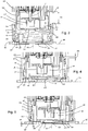
- Fig. 3 shows for the in Fig. 1 shown first position of the adjusting means or at least part of the adjusting means ring DR a section through the lower area of the submersible pump.
- the underside of the base plate GP forms a standing plane SE, which is typically oriented at least approximately horizontally in pump operation.
- water is sucked in through a lower inlet opening EO of the pump chamber and via the in Fig. 1 shown output channel AK to the output port AA of the pump.
- the lower edge UK of the lower housing part is preferably in this first position of the rotating ring above the upper edge of the recesses OR, so that the in Fig.
- the height of the through openings DO denoted by HO is completely available as the clear height HS for the suction of water, including solid bodies carried with it. If the transverse dimension of the through openings DO is smaller than their height HO, this width of the through openings determines the opening width of the through openings and the maximum diameter of conveyable solid bodies.
- the diameter of the inlet opening EO into the pump chamber is at least a little larger than the maximum opening width of the through openings DO, so that larger solids are already held at the through openings DO and cannot block the inlet opening EO within the ring DR.
- the lower edge UK of the lower housing part GU lies in the first position of the adjusting means containing the rotating ring DR above the upper edge of the cutouts OR, so that their opening width is not restricted by the lower housing part.
- An upper edge RO of the ring DR is vertically spaced from a lower edge UO of the upper part of the pump housing by a distance DS which is greater than the height HS of the passage openings.
- the ring DR in the in Fig. 1 and Fig. 2 DB designated movement sequence, which includes a rotation about the axis of rotation DA with simultaneous movement of the ring in the direction parallel to the axis of rotation DA
- the ring DR in the Fig. 4 in to Fig. 3 Analog sectional drawing shown second position of the adjusting means are brought.
- the clear height of the through openings DO is limited by the lower edge UK of the lower housing part to a value HK, which is, for example, a maximum of 8 mm, in particular a maximum of 6 mm.
- the diameter of solids which can be sucked in through the passage opening DO is therefore also limited to these dimensions and the pump works like a clear water pump.
- the pump housing is closer to the standing plane SE in the second position than in the first position and the upper edge RO of the ring DR is spaced apart from the lower edge UG of the upper part GO of the housing by a reduced amount DK.
- a collar KR also projects downward from the underside of the pump chamber, which can be radially spaced from the inlet opening EO in the pump chamber by a small amount with respect to the axis of rotation RA and is formed all around the inlet opening.
- Such a collar molded onto the underside of the pump chamber can lower the level above the standing level SE, up to which water can be drawn off by the pump, so that the pump can also be used for flat suction.
- Such a flat suction position is in Fig. 5 outlined and can by rotating the ring DR about the axis of rotation DA beyond the second position Fig. 4 be adjusted.
- the rotation can be limited, for example, by the upper edge RO of the ring DR abutting a lower edge UO of the upper housing part GO.
- a limitation of the sequence of movements is alternatively or simultaneously also possible by abutment of the lower edge of the lower housing part on the upper side PP on the ring DR held by the base plate GP or by other means known to the person skilled in the art.
- the collar KR around the inlet opening EO essentially stands on the lowered ring surface GG.
- a flow of water through the recesses OR is practically prevented by the bottom edge UK of the bottom part GU or the bottom of the pump chamber on the top PP of the base plate or in particular by the collar KR on the lowered annular surface GG and water flows under the base plate through there over the Floor level SE, free spaces BK to the center of the base plate and through the grid GI into the inlet opening EO of the pump chamber LK.
- a residual water level HF up to which the pump can draw water from the environment in this flat suction position, is with sufficient airtight closure of the previous flow path above the base plate GP by the height of the free spaces BK, otherwise by the height of the collar KR around the inlet opening EO above the Stand level determined.
- the residual water height HF is advantageously not more than 3 mm, in particular not more than 2 mm.
- the ring DR can advantageously be set in another position relative to the pump housing in one or more intermediate positions and z. B. can be fixed by means of the clamping screw KS against unintentional rotation, which results in different opening widths of the passage openings. Due to the fact that a selected position of the rotating ring can be fixed, the size of the flow openings and the residual water level are maintained during pump operation.
- the different opening widths of the passage openings are correlated with the height of the inlet opening EO of the pump chamber above the level SE, so that depending on the position of the ring DR relative to the pump housing, there are also different water levels up to which the pump can draw water from the environment.
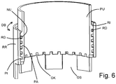
- Fig. 6 shows schematically a lower section PU of a pump housing and a height-adjustable ring RR held thereon by means of a threaded connection, which in turn can be displaced relative to the pump housing by means of a screw rotary movement DB.
- an external thread PA that winds several times around the pump housing is formed on the outer wall of the pump housing PU, and an internal thread PI on the inner wall of the ring RR is only slightly threaded, for example, is only wound once around an axis of rotation DA or is also divided into sections , executed.
- an elastically deformable ring element RD is inserted, which rests under elastic prestress on the inner surface RI of the ring RR and forms a friction element, the static friction forces of which relate to the outer wall of the pump housing and / or the surface RI of the ring RR as a static frictional force, a holding force against unintentional rotation of the ring RR in the threaded connection PA, PI causes relative to the pump housing PU.
- the static friction force can advantageously be overcome by a user force.
- the ring element RD as a friction element can be designed, for example, as a rubber-elastic O-ring.
- the ring element RD as a friction element does not need to perform a sealing function against undesired suction of air through the gap with the threaded connection between the ring RR and the pump housing PU, since in this case the minimum achievable water level in the vicinity of the submersible pump is determined by the lower edge of the pump housing PU is.
- separate recesses OK are provided on the lower edge UG of the pump housing PU, which, in a second position of the ring RR relative to the pump housing PU, has the lower edge UG of the pump housing completely lowered to a level, the opening widths of through openings to a small value corresponding to clear water operation limit the submersible pump.
- intermediate positions of the ring RR are relative to the pump housing PU between the second position and that in FIG Fig. 6 shown first position possible, in particular the ring RR can be adjusted continuously relative to the pump housing PU.
- the ring RR can in turn be closed at the bottom by a base plate.
Landscapes
- Engineering & Computer Science (AREA)
- Mechanical Engineering (AREA)
- General Engineering & Computer Science (AREA)
- Structures Of Non-Positive Displacement Pumps (AREA)
- Glass Compositions (AREA)
- Pharmaceuticals Containing Other Organic And Inorganic Compounds (AREA)
Priority Applications (7)
| Application Number | Priority Date | Filing Date | Title |
|---|---|---|---|
| ES12195386T ES2781777T3 (es) | 2012-12-04 | 2012-12-04 | Bomba sumergible |
| EP12195386.3A EP2740940B1 (de) | 2012-12-04 | 2012-12-04 | Tauchpumpe |
| DK12195386.3T DK2740940T3 (da) | 2012-12-04 | 2012-12-04 | Dykpumpe |
| PL12195386T PL2740940T3 (pl) | 2012-12-04 | 2012-12-04 | Pompa zanurzeniowa |
| PT121953863T PT2740940T (pt) | 2012-12-04 | 2012-12-04 | Bomba submersível |
| AU2013267008A AU2013267008A1 (en) | 2012-12-04 | 2013-12-04 | Immersion pump |
| HRP20200509TT HRP20200509T1 (hr) | 2012-12-04 | 2020-03-27 | Potopna crpka |
Applications Claiming Priority (1)
| Application Number | Priority Date | Filing Date | Title |
|---|---|---|---|
| EP12195386.3A EP2740940B1 (de) | 2012-12-04 | 2012-12-04 | Tauchpumpe |
Publications (2)
| Publication Number | Publication Date |
|---|---|
| EP2740940A1 EP2740940A1 (de) | 2014-06-11 |
| EP2740940B1 true EP2740940B1 (de) | 2020-03-04 |
Family
ID=47263174
Family Applications (1)
| Application Number | Title | Priority Date | Filing Date |
|---|---|---|---|
| EP12195386.3A Active EP2740940B1 (de) | 2012-12-04 | 2012-12-04 | Tauchpumpe |
Country Status (7)
| Country | Link |
|---|---|
| EP (1) | EP2740940B1 (pl) |
| AU (1) | AU2013267008A1 (pl) |
| DK (1) | DK2740940T3 (pl) |
| ES (1) | ES2781777T3 (pl) |
| HR (1) | HRP20200509T1 (pl) |
| PL (1) | PL2740940T3 (pl) |
| PT (1) | PT2740940T (pl) |
Families Citing this family (9)
| Publication number | Priority date | Publication date | Assignee | Title |
|---|---|---|---|---|
| WO2016008510A1 (de) * | 2014-07-15 | 2016-01-21 | Alfred Kärcher Gmbh & Co. Kg | Tauchpumpe |
| EP3332127B1 (en) * | 2015-08-03 | 2020-01-29 | Husqvarna AB | Submersible pump with float switch and float switch cable clip restrictor |
| FR3096093B1 (fr) * | 2019-05-14 | 2023-02-24 | Ams R&D Sas | Dispositif pour l’aspiration de liquide se trouvant sur un sol. |
| EP3981989A1 (en) * | 2020-10-07 | 2022-04-13 | Husqvarna Ab | Mechanism for pump |
| CN112922851B (zh) * | 2021-02-05 | 2022-11-11 | 浙江丰源泵业有限公司 | 潜水泵 |
| CN115788919A (zh) | 2021-09-09 | 2023-03-14 | 创科无线普通合伙 | 潜水泵 |
| CN116557304B (zh) * | 2023-05-22 | 2026-02-06 | 宁波君禾智能科技有限公司 | 一种潜水泵 |
| BE1032704B1 (de) * | 2024-06-18 | 2026-01-28 | Wilo Se | Kreiselpumpe |
| BE1032703B1 (de) * | 2024-06-18 | 2026-01-28 | Wilo Se | Kreiselpumpe |
Family Cites Families (4)
| Publication number | Priority date | Publication date | Assignee | Title |
|---|---|---|---|---|
| DE10044966B4 (de) | 2000-09-11 | 2004-07-15 | Gardena Manufacturing Gmbh | Tauchpumpe |
| JP2004285913A (ja) * | 2003-03-20 | 2004-10-14 | Creator:Kk | 工事現場用の大型水中ポンプ |
| DE102005031420B4 (de) | 2005-07-04 | 2010-07-08 | Al-Ko Kober Ag | Kombinierte Tauch-/Flachabsaug-Rotationspumpe mit konzentrischer Laufradeintrittsöffnung |
| AT11893U1 (de) * | 2010-02-03 | 2011-06-15 | Rosenbauer Int Ag | Tauchpumpe |
-
2012
- 2012-12-04 PT PT121953863T patent/PT2740940T/pt unknown
- 2012-12-04 PL PL12195386T patent/PL2740940T3/pl unknown
- 2012-12-04 DK DK12195386.3T patent/DK2740940T3/da active
- 2012-12-04 ES ES12195386T patent/ES2781777T3/es active Active
- 2012-12-04 EP EP12195386.3A patent/EP2740940B1/de active Active
-
2013
- 2013-12-04 AU AU2013267008A patent/AU2013267008A1/en not_active Abandoned
-
2020
- 2020-03-27 HR HRP20200509TT patent/HRP20200509T1/hr unknown
Non-Patent Citations (1)
| Title |
|---|
| None * |
Also Published As
| Publication number | Publication date |
|---|---|
| PT2740940T (pt) | 2020-04-02 |
| DK2740940T3 (da) | 2020-04-06 |
| ES2781777T3 (es) | 2020-09-07 |
| HRP20200509T1 (hr) | 2020-06-26 |
| EP2740940A1 (de) | 2014-06-11 |
| PL2740940T3 (pl) | 2020-07-13 |
| AU2013267008A1 (en) | 2014-06-19 |
Similar Documents
| Publication | Publication Date | Title |
|---|---|---|
| EP2740940B1 (de) | Tauchpumpe | |
| DE2032938C3 (de) | Dämpfungsvorrichtung für Rotationsbewegungen | |
| DE3718325C2 (de) | Fasspumpe | |
| WO2019048099A1 (de) | Strahlregler | |
| DE2139497A1 (de) | Emulgier- und dispergiervorrichtung | |
| DE1403836B1 (de) | Ventillose Zweiwegezentrifugalpumpe | |
| DE4325837C2 (de) | Sicherheitsverbinder für die Infusionstherapie | |
| DE102016123171A1 (de) | Laufrad und Pumpe verwendend das Laufrad | |
| WO2020182921A9 (de) | Ventilanordnungen für eine membranpumpe | |
| DE69802195T2 (de) | Pumpengehaüse und verfahren zur dessen herstellung | |
| DE20300155U1 (de) | Wasserpumpenmotor | |
| DE202018106483U1 (de) | Eine an Pumpe angebrachte Struktur mit a höhenverstellbarer Basis | |
| DE4224664A1 (de) | Rotordüse, insbesondere für ein mit Reinigungsflüssigkeit arbeitendes Hochdruckreinigungsgerät | |
| DE1609199A1 (de) | Brausekopf | |
| EP0410198A2 (de) | Versenkregner | |
| DE202012007884U1 (de) | Einweg-Ventileinrichtung | |
| DE102014118210B4 (de) | Mehrflutige Strömungsmaschine | |
| DE29718219U1 (de) | Vorrichtung zur Änderung der Auslaßrichtung für Wasserpumpen | |
| EP4001655B1 (de) | Tauchdruckpumpe für flüssigkeit und deren verwendung | |
| DE1632916A1 (de) | Beregner | |
| DE574323C (de) | Fluegelradpumpe mit umlaufender, abdichtender Hilfsfluessigkeit und einem oder mehreren seitlich des Fluegelrades im Pumpengehaeuse angeordneten Leitkanaelen | |
| DE949765C (de) | Fluessigkeitsringgaspumpe | |
| DE202022100208U1 (de) | Pumpe mit flexiblem Laufrad | |
| DE102016116174B3 (de) | Ausgiesser mit geringem durchfluss | |
| EP4421325A1 (de) | Kreiselpumpe, insbesondere bohrlochpumpe |
Legal Events
| Date | Code | Title | Description |
|---|---|---|---|
| PUAI | Public reference made under article 153(3) epc to a published international application that has entered the european phase |
Free format text: ORIGINAL CODE: 0009012 |
|
| 17P | Request for examination filed |
Effective date: 20121204 |
|
| AK | Designated contracting states |
Kind code of ref document: A1 Designated state(s): AL AT BE BG CH CY CZ DE DK EE ES FI FR GB GR HR HU IE IS IT LI LT LU LV MC MK MT NL NO PL PT RO RS SE SI SK SM TR |
|
| AX | Request for extension of the european patent |
Extension state: BA ME |
|
| R17P | Request for examination filed (corrected) |
Effective date: 20141210 |
|
| RBV | Designated contracting states (corrected) |
Designated state(s): AL AT BE BG CH CY CZ DE DK EE ES FI FR GB GR HR HU IE IS IT LI LT LU LV MC MK MT NL NO PL PT RO RS SE SI SK SM TR |
|
| STAA | Information on the status of an ep patent application or granted ep patent |
Free format text: STATUS: EXAMINATION IS IN PROGRESS |
|
| 17Q | First examination report despatched |
Effective date: 20190715 |
|
| GRAP | Despatch of communication of intention to grant a patent |
Free format text: ORIGINAL CODE: EPIDOSNIGR1 |
|
| STAA | Information on the status of an ep patent application or granted ep patent |
Free format text: STATUS: GRANT OF PATENT IS INTENDED |
|
| INTG | Intention to grant announced |
Effective date: 20191111 |
|
| GRAS | Grant fee paid |
Free format text: ORIGINAL CODE: EPIDOSNIGR3 |
|
| GRAA | (expected) grant |
Free format text: ORIGINAL CODE: 0009210 |
|
| STAA | Information on the status of an ep patent application or granted ep patent |
Free format text: STATUS: THE PATENT HAS BEEN GRANTED |
|
| AK | Designated contracting states |
Kind code of ref document: B1 Designated state(s): AL AT BE BG CH CY CZ DE DK EE ES FI FR GB GR HR HU IE IS IT LI LT LU LV MC MK MT NL NO PL PT RO RS SE SI SK SM TR |
|
| REG | Reference to a national code |
Ref country code: GB Ref legal event code: FG4D Free format text: NOT ENGLISH |
|
| REG | Reference to a national code |
Ref country code: CH Ref legal event code: EP |
|
| REG | Reference to a national code |
Ref country code: AT Ref legal event code: REF Ref document number: 1240676 Country of ref document: AT Kind code of ref document: T Effective date: 20200315 |
|
| REG | Reference to a national code |
Ref country code: DE Ref legal event code: R096 Ref document number: 502012015826 Country of ref document: DE Ref country code: RO Ref legal event code: EPE |
|
| REG | Reference to a national code |
Ref country code: HR Ref legal event code: TUEP Ref document number: P20200509T Country of ref document: HR |
|
| REG | Reference to a national code |
Ref country code: FI Ref legal event code: FGE Ref country code: IE Ref legal event code: FG4D Free format text: LANGUAGE OF EP DOCUMENT: GERMAN |
|
| REG | Reference to a national code |
Ref country code: PT Ref legal event code: SC4A Ref document number: 2740940 Country of ref document: PT Date of ref document: 20200402 Kind code of ref document: T Free format text: AVAILABILITY OF NATIONAL TRANSLATION Effective date: 20200324 |
|
| REG | Reference to a national code |
Ref country code: DK Ref legal event code: T3 Effective date: 20200330 |
|
| REG | Reference to a national code |
Ref country code: NL Ref legal event code: FP |
|
| REG | Reference to a national code |
Ref country code: SE Ref legal event code: TRGR |
|
| REG | Reference to a national code |
Ref country code: HR Ref legal event code: T1PR Ref document number: P20200509 Country of ref document: HR |
|
| PG25 | Lapsed in a contracting state [announced via postgrant information from national office to epo] |
Ref country code: NO Free format text: LAPSE BECAUSE OF FAILURE TO SUBMIT A TRANSLATION OF THE DESCRIPTION OR TO PAY THE FEE WITHIN THE PRESCRIBED TIME-LIMIT Effective date: 20200604 Ref country code: RS Free format text: LAPSE BECAUSE OF FAILURE TO SUBMIT A TRANSLATION OF THE DESCRIPTION OR TO PAY THE FEE WITHIN THE PRESCRIBED TIME-LIMIT Effective date: 20200304 |
|
| PG25 | Lapsed in a contracting state [announced via postgrant information from national office to epo] |
Ref country code: GR Free format text: LAPSE BECAUSE OF FAILURE TO SUBMIT A TRANSLATION OF THE DESCRIPTION OR TO PAY THE FEE WITHIN THE PRESCRIBED TIME-LIMIT Effective date: 20200605 Ref country code: BG Free format text: LAPSE BECAUSE OF FAILURE TO SUBMIT A TRANSLATION OF THE DESCRIPTION OR TO PAY THE FEE WITHIN THE PRESCRIBED TIME-LIMIT Effective date: 20200604 Ref country code: LV Free format text: LAPSE BECAUSE OF FAILURE TO SUBMIT A TRANSLATION OF THE DESCRIPTION OR TO PAY THE FEE WITHIN THE PRESCRIBED TIME-LIMIT Effective date: 20200304 |
|
| REG | Reference to a national code |
Ref country code: ES Ref legal event code: FG2A Ref document number: 2781777 Country of ref document: ES Kind code of ref document: T3 Effective date: 20200907 |
|
| REG | Reference to a national code |
Ref country code: LT Ref legal event code: MG4D |
|
| PG25 | Lapsed in a contracting state [announced via postgrant information from national office to epo] |
Ref country code: LT Free format text: LAPSE BECAUSE OF FAILURE TO SUBMIT A TRANSLATION OF THE DESCRIPTION OR TO PAY THE FEE WITHIN THE PRESCRIBED TIME-LIMIT Effective date: 20200304 Ref country code: IS Free format text: LAPSE BECAUSE OF FAILURE TO SUBMIT A TRANSLATION OF THE DESCRIPTION OR TO PAY THE FEE WITHIN THE PRESCRIBED TIME-LIMIT Effective date: 20200704 Ref country code: SM Free format text: LAPSE BECAUSE OF FAILURE TO SUBMIT A TRANSLATION OF THE DESCRIPTION OR TO PAY THE FEE WITHIN THE PRESCRIBED TIME-LIMIT Effective date: 20200304 Ref country code: EE Free format text: LAPSE BECAUSE OF FAILURE TO SUBMIT A TRANSLATION OF THE DESCRIPTION OR TO PAY THE FEE WITHIN THE PRESCRIBED TIME-LIMIT Effective date: 20200304 Ref country code: SK Free format text: LAPSE BECAUSE OF FAILURE TO SUBMIT A TRANSLATION OF THE DESCRIPTION OR TO PAY THE FEE WITHIN THE PRESCRIBED TIME-LIMIT Effective date: 20200304 |
|
| REG | Reference to a national code |
Ref country code: DE Ref legal event code: R097 Ref document number: 502012015826 Country of ref document: DE |
|
| REG | Reference to a national code |
Ref country code: HR Ref legal event code: ODRP Ref document number: P20200509 Country of ref document: HR Payment date: 20201123 Year of fee payment: 9 |
|
| PLBE | No opposition filed within time limit |
Free format text: ORIGINAL CODE: 0009261 |
|
| STAA | Information on the status of an ep patent application or granted ep patent |
Free format text: STATUS: NO OPPOSITION FILED WITHIN TIME LIMIT |
|
| 26N | No opposition filed |
Effective date: 20201207 |
|
| PG25 | Lapsed in a contracting state [announced via postgrant information from national office to epo] |
Ref country code: SI Free format text: LAPSE BECAUSE OF FAILURE TO SUBMIT A TRANSLATION OF THE DESCRIPTION OR TO PAY THE FEE WITHIN THE PRESCRIBED TIME-LIMIT Effective date: 20200304 |
|
| PG25 | Lapsed in a contracting state [announced via postgrant information from national office to epo] |
Ref country code: MC Free format text: LAPSE BECAUSE OF FAILURE TO SUBMIT A TRANSLATION OF THE DESCRIPTION OR TO PAY THE FEE WITHIN THE PRESCRIBED TIME-LIMIT Effective date: 20200304 |
|
| PG25 | Lapsed in a contracting state [announced via postgrant information from national office to epo] |
Ref country code: IE Free format text: LAPSE BECAUSE OF NON-PAYMENT OF DUE FEES Effective date: 20201204 |
|
| REG | Reference to a national code |
Ref country code: HR Ref legal event code: ODRP Ref document number: P20200509 Country of ref document: HR Payment date: 20211129 Year of fee payment: 10 |
|
| PG25 | Lapsed in a contracting state [announced via postgrant information from national office to epo] |
Ref country code: MT Free format text: LAPSE BECAUSE OF FAILURE TO SUBMIT A TRANSLATION OF THE DESCRIPTION OR TO PAY THE FEE WITHIN THE PRESCRIBED TIME-LIMIT Effective date: 20200304 Ref country code: CY Free format text: LAPSE BECAUSE OF FAILURE TO SUBMIT A TRANSLATION OF THE DESCRIPTION OR TO PAY THE FEE WITHIN THE PRESCRIBED TIME-LIMIT Effective date: 20200304 |
|
| PG25 | Lapsed in a contracting state [announced via postgrant information from national office to epo] |
Ref country code: MK Free format text: LAPSE BECAUSE OF FAILURE TO SUBMIT A TRANSLATION OF THE DESCRIPTION OR TO PAY THE FEE WITHIN THE PRESCRIBED TIME-LIMIT Effective date: 20200304 Ref country code: AL Free format text: LAPSE BECAUSE OF FAILURE TO SUBMIT A TRANSLATION OF THE DESCRIPTION OR TO PAY THE FEE WITHIN THE PRESCRIBED TIME-LIMIT Effective date: 20200304 |
|
| REG | Reference to a national code |
Ref country code: HR Ref legal event code: ODRP Ref document number: P20200509 Country of ref document: HR Payment date: 20221124 Year of fee payment: 11 |
|
| PGFP | Annual fee paid to national office [announced via postgrant information from national office to epo] |
Ref country code: SE Payment date: 20221221 Year of fee payment: 11 Ref country code: NL Payment date: 20221220 Year of fee payment: 11 Ref country code: LU Payment date: 20221219 Year of fee payment: 11 Ref country code: GB Payment date: 20221222 Year of fee payment: 11 Ref country code: FR Payment date: 20221219 Year of fee payment: 11 Ref country code: FI Payment date: 20221216 Year of fee payment: 11 Ref country code: DK Payment date: 20221221 Year of fee payment: 11 Ref country code: AT Payment date: 20221216 Year of fee payment: 11 |
|
| PGFP | Annual fee paid to national office [announced via postgrant information from national office to epo] |
Ref country code: BE Payment date: 20221220 Year of fee payment: 11 |
|
| PGFP | Annual fee paid to national office [announced via postgrant information from national office to epo] |
Ref country code: ES Payment date: 20230119 Year of fee payment: 11 Ref country code: CH Payment date: 20230103 Year of fee payment: 11 |
|
| PGFP | Annual fee paid to national office [announced via postgrant information from national office to epo] |
Ref country code: IT Payment date: 20221230 Year of fee payment: 11 Ref country code: DE Payment date: 20221221 Year of fee payment: 11 |
|
| REG | Reference to a national code |
Ref country code: HR Ref legal event code: ODRP Ref document number: P20200509 Country of ref document: HR Payment date: 20231123 Year of fee payment: 12 |
|
| PGFP | Annual fee paid to national office [announced via postgrant information from national office to epo] |
Ref country code: TR Payment date: 20231127 Year of fee payment: 12 Ref country code: RO Payment date: 20231127 Year of fee payment: 12 Ref country code: PT Payment date: 20231120 Year of fee payment: 12 Ref country code: HR Payment date: 20231123 Year of fee payment: 12 Ref country code: CZ Payment date: 20231121 Year of fee payment: 12 |
|
| PGFP | Annual fee paid to national office [announced via postgrant information from national office to epo] |
Ref country code: PL Payment date: 20231123 Year of fee payment: 12 |
|
| REG | Reference to a national code |
Ref country code: DE Ref legal event code: R119 Ref document number: 502012015826 Country of ref document: DE |
|
| REG | Reference to a national code |
Ref country code: DK Ref legal event code: EBP Effective date: 20231231 |
|
| REG | Reference to a national code |
Ref country code: SE Ref legal event code: EUG |
|
| PG25 | Lapsed in a contracting state [announced via postgrant information from national office to epo] |
Ref country code: FI Free format text: LAPSE BECAUSE OF NON-PAYMENT OF DUE FEES Effective date: 20231204 |
|
| REG | Reference to a national code |
Ref country code: CH Ref legal event code: PL |
|
| REG | Reference to a national code |
Ref country code: NL Ref legal event code: MM Effective date: 20240101 |
|
| REG | Reference to a national code |
Ref country code: AT Ref legal event code: MM01 Ref document number: 1240676 Country of ref document: AT Kind code of ref document: T Effective date: 20231204 |
|
| PG25 | Lapsed in a contracting state [announced via postgrant information from national office to epo] |
Ref country code: LU Free format text: LAPSE BECAUSE OF NON-PAYMENT OF DUE FEES Effective date: 20231204 |
|
| GBPC | Gb: european patent ceased through non-payment of renewal fee |
Effective date: 20231204 |
|
| REG | Reference to a national code |
Ref country code: BE Ref legal event code: MM Effective date: 20231231 |
|
| PG25 | Lapsed in a contracting state [announced via postgrant information from national office to epo] |
Ref country code: LU Free format text: LAPSE BECAUSE OF NON-PAYMENT OF DUE FEES Effective date: 20231204 |
|
| PG25 | Lapsed in a contracting state [announced via postgrant information from national office to epo] |
Ref country code: NL Free format text: LAPSE BECAUSE OF NON-PAYMENT OF DUE FEES Effective date: 20240101 |
|
| PG25 | Lapsed in a contracting state [announced via postgrant information from national office to epo] |
Ref country code: NL Free format text: LAPSE BECAUSE OF NON-PAYMENT OF DUE FEES Effective date: 20240101 |
|
| PG25 | Lapsed in a contracting state [announced via postgrant information from national office to epo] |
Ref country code: DE Free format text: LAPSE BECAUSE OF NON-PAYMENT OF DUE FEES Effective date: 20240702 |
|
| PG25 | Lapsed in a contracting state [announced via postgrant information from national office to epo] |
Ref country code: GB Free format text: LAPSE BECAUSE OF NON-PAYMENT OF DUE FEES Effective date: 20231204 |
|
| PG25 | Lapsed in a contracting state [announced via postgrant information from national office to epo] |
Ref country code: BE Free format text: LAPSE BECAUSE OF NON-PAYMENT OF DUE FEES Effective date: 20231231 |
|
| PG25 | Lapsed in a contracting state [announced via postgrant information from national office to epo] |
Ref country code: FR Free format text: LAPSE BECAUSE OF NON-PAYMENT OF DUE FEES Effective date: 20231231 |
|
| PG25 | Lapsed in a contracting state [announced via postgrant information from national office to epo] |
Ref country code: CH Free format text: LAPSE BECAUSE OF NON-PAYMENT OF DUE FEES Effective date: 20231231 |
|
| PG25 | Lapsed in a contracting state [announced via postgrant information from national office to epo] |
Ref country code: AT Free format text: LAPSE BECAUSE OF NON-PAYMENT OF DUE FEES Effective date: 20231204 |
|
| PG25 | Lapsed in a contracting state [announced via postgrant information from national office to epo] |
Ref country code: GB Free format text: LAPSE BECAUSE OF NON-PAYMENT OF DUE FEES Effective date: 20231204 Ref country code: FR Free format text: LAPSE BECAUSE OF NON-PAYMENT OF DUE FEES Effective date: 20231231 Ref country code: DE Free format text: LAPSE BECAUSE OF NON-PAYMENT OF DUE FEES Effective date: 20240702 Ref country code: CH Free format text: LAPSE BECAUSE OF NON-PAYMENT OF DUE FEES Effective date: 20231231 Ref country code: BE Free format text: LAPSE BECAUSE OF NON-PAYMENT OF DUE FEES Effective date: 20231231 Ref country code: AT Free format text: LAPSE BECAUSE OF NON-PAYMENT OF DUE FEES Effective date: 20231204 |
|
| PG25 | Lapsed in a contracting state [announced via postgrant information from national office to epo] |
Ref country code: DK Free format text: LAPSE BECAUSE OF NON-PAYMENT OF DUE FEES Effective date: 20231231 |
|
| REG | Reference to a national code |
Ref country code: ES Ref legal event code: FD2A Effective date: 20250124 |
|
| PG25 | Lapsed in a contracting state [announced via postgrant information from national office to epo] |
Ref country code: DK Free format text: LAPSE BECAUSE OF NON-PAYMENT OF DUE FEES Effective date: 20231231 |
|
| PG25 | Lapsed in a contracting state [announced via postgrant information from national office to epo] |
Ref country code: ES Free format text: LAPSE BECAUSE OF NON-PAYMENT OF DUE FEES Effective date: 20231205 |
|
| REG | Reference to a national code |
Ref country code: HR Ref legal event code: PBON Ref document number: P20200509 Country of ref document: HR Effective date: 20241204 |
|
| PG25 | Lapsed in a contracting state [announced via postgrant information from national office to epo] |
Ref country code: PT Free format text: LAPSE BECAUSE OF NON-PAYMENT OF DUE FEES Effective date: 20250604 |
|
| PG25 | Lapsed in a contracting state [announced via postgrant information from national office to epo] |
Ref country code: RO Free format text: LAPSE BECAUSE OF NON-PAYMENT OF DUE FEES Effective date: 20241204 |
|
| PG25 | Lapsed in a contracting state [announced via postgrant information from national office to epo] |
Ref country code: CZ Free format text: LAPSE BECAUSE OF NON-PAYMENT OF DUE FEES Effective date: 20241204 |
|
| PG25 | Lapsed in a contracting state [announced via postgrant information from national office to epo] |
Ref country code: IT Free format text: LAPSE BECAUSE OF NON-PAYMENT OF DUE FEES Effective date: 20231204 |
|
| PG25 | Lapsed in a contracting state [announced via postgrant information from national office to epo] |
Ref country code: SE Free format text: LAPSE BECAUSE OF NON-PAYMENT OF DUE FEES Effective date: 20231205 |
|
| PG25 | Lapsed in a contracting state [announced via postgrant information from national office to epo] |
Ref country code: HR Free format text: LAPSE BECAUSE OF NON-PAYMENT OF DUE FEES Effective date: 20241204 |