EP2743434B1 - Charnière de portière automobile à construction de plusieurs pièces - Google Patents
Charnière de portière automobile à construction de plusieurs pièces Download PDFInfo
- Publication number
- EP2743434B1 EP2743434B1 EP14159033.1A EP14159033A EP2743434B1 EP 2743434 B1 EP2743434 B1 EP 2743434B1 EP 14159033 A EP14159033 A EP 14159033A EP 2743434 B1 EP2743434 B1 EP 2743434B1
- Authority
- EP
- European Patent Office
- Prior art keywords
- pivot
- door
- angle brackets
- component
- hinge assembly
- Prior art date
- Legal status (The legal status is an assumption and is not a legal conclusion. Google has not performed a legal analysis and makes no representation as to the accuracy of the status listed.)
- Active
Links
Images





Classifications
-
- E—FIXED CONSTRUCTIONS
- E05—LOCKS; KEYS; WINDOW OR DOOR FITTINGS; SAFES
- E05D—HINGES OR SUSPENSION DEVICES FOR DOORS, WINDOWS OR WINGS
- E05D3/00—Hinges with pins
- E05D3/02—Hinges with pins with one pin
-
- E—FIXED CONSTRUCTIONS
- E05—LOCKS; KEYS; WINDOW OR DOOR FITTINGS; SAFES
- E05D—HINGES OR SUSPENSION DEVICES FOR DOORS, WINDOWS OR WINGS
- E05D11/00—Additional features or accessories of hinges
- E05D11/06—Devices for limiting the opening movement of hinges
-
- E—FIXED CONSTRUCTIONS
- E05—LOCKS; KEYS; WINDOW OR DOOR FITTINGS; SAFES
- E05D—HINGES OR SUSPENSION DEVICES FOR DOORS, WINDOWS OR WINGS
- E05D5/00—Construction of single parts, e.g. the parts for attachment
- E05D5/02—Parts for attachment, e.g. flaps
-
- E—FIXED CONSTRUCTIONS
- E05—LOCKS; KEYS; WINDOW OR DOOR FITTINGS; SAFES
- E05D—HINGES OR SUSPENSION DEVICES FOR DOORS, WINDOWS OR WINGS
- E05D5/00—Construction of single parts, e.g. the parts for attachment
- E05D5/02—Parts for attachment, e.g. flaps
- E05D5/0207—Parts for attachment, e.g. flaps for attachment to vehicles
-
- E—FIXED CONSTRUCTIONS
- E05—LOCKS; KEYS; WINDOW OR DOOR FITTINGS; SAFES
- E05D—HINGES OR SUSPENSION DEVICES FOR DOORS, WINDOWS OR WINGS
- E05D5/00—Construction of single parts, e.g. the parts for attachment
- E05D5/02—Parts for attachment, e.g. flaps
- E05D5/06—Bent flaps
- E05D5/062—Bent flaps specially adapted for vehicles
-
- E—FIXED CONSTRUCTIONS
- E05—LOCKS; KEYS; WINDOW OR DOOR FITTINGS; SAFES
- E05D—HINGES OR SUSPENSION DEVICES FOR DOORS, WINDOWS OR WINGS
- E05D5/00—Construction of single parts, e.g. the parts for attachment
- E05D5/10—Pins, sockets or sleeves; Removable pins
-
- E—FIXED CONSTRUCTIONS
- E05—LOCKS; KEYS; WINDOW OR DOOR FITTINGS; SAFES
- E05D—HINGES OR SUSPENSION DEVICES FOR DOORS, WINDOWS OR WINGS
- E05D5/00—Construction of single parts, e.g. the parts for attachment
- E05D5/10—Pins, sockets or sleeves; Removable pins
- E05D5/12—Securing pins in sockets, movably or not
-
- E—FIXED CONSTRUCTIONS
- E05—LOCKS; KEYS; WINDOW OR DOOR FITTINGS; SAFES
- E05D—HINGES OR SUSPENSION DEVICES FOR DOORS, WINDOWS OR WINGS
- E05D5/00—Construction of single parts, e.g. the parts for attachment
- E05D5/10—Pins, sockets or sleeves; Removable pins
- E05D5/12—Securing pins in sockets, movably or not
- E05D5/127—Securing pins in sockets, movably or not by forcing the pin into the socket
-
- E—FIXED CONSTRUCTIONS
- E05—LOCKS; KEYS; WINDOW OR DOOR FITTINGS; SAFES
- E05D—HINGES OR SUSPENSION DEVICES FOR DOORS, WINDOWS OR WINGS
- E05D9/00—Flaps or sleeves specially designed for making from particular material, e.g. hoop-iron, sheet metal, plastics
-
- E—FIXED CONSTRUCTIONS
- E05—LOCKS; KEYS; WINDOW OR DOOR FITTINGS; SAFES
- E05D—HINGES OR SUSPENSION DEVICES FOR DOORS, WINDOWS OR WINGS
- E05D3/00—Hinges with pins
- E05D3/02—Hinges with pins with one pin
- E05D2003/025—Hinges with pins with one pin having three knuckles
-
- E—FIXED CONSTRUCTIONS
- E05—LOCKS; KEYS; WINDOW OR DOOR FITTINGS; SAFES
- E05D—HINGES OR SUSPENSION DEVICES FOR DOORS, WINDOWS OR WINGS
- E05D5/00—Construction of single parts, e.g. the parts for attachment
- E05D5/10—Pins, sockets or sleeves; Removable pins
- E05D2005/102—Pins
-
- E—FIXED CONSTRUCTIONS
- E05—LOCKS; KEYS; WINDOW OR DOOR FITTINGS; SAFES
- E05Y—INDEXING SCHEME ASSOCIATED WITH SUBCLASSES E05D AND E05F, RELATING TO CONSTRUCTION ELEMENTS, ELECTRIC CONTROL, POWER SUPPLY, POWER SIGNAL OR TRANSMISSION, USER INTERFACES, MOUNTING OR COUPLING, DETAILS, ACCESSORIES, AUXILIARY OPERATIONS NOT OTHERWISE PROVIDED FOR, APPLICATION THEREOF
- E05Y2600/00—Mounting or coupling arrangements for elements provided for in this subclass
- E05Y2600/50—Mounting methods; Positioning
- E05Y2600/506—Plastic deformation
-
- E—FIXED CONSTRUCTIONS
- E05—LOCKS; KEYS; WINDOW OR DOOR FITTINGS; SAFES
- E05Y—INDEXING SCHEME ASSOCIATED WITH SUBCLASSES E05D AND E05F, RELATING TO CONSTRUCTION ELEMENTS, ELECTRIC CONTROL, POWER SUPPLY, POWER SIGNAL OR TRANSMISSION, USER INTERFACES, MOUNTING OR COUPLING, DETAILS, ACCESSORIES, AUXILIARY OPERATIONS NOT OTHERWISE PROVIDED FOR, APPLICATION THEREOF
- E05Y2600/00—Mounting or coupling arrangements for elements provided for in this subclass
- E05Y2600/50—Mounting methods; Positioning
- E05Y2600/506—Plastic deformation
- E05Y2600/508—Riveting
-
- E—FIXED CONSTRUCTIONS
- E05—LOCKS; KEYS; WINDOW OR DOOR FITTINGS; SAFES
- E05Y—INDEXING SCHEME ASSOCIATED WITH SUBCLASSES E05D AND E05F, RELATING TO CONSTRUCTION ELEMENTS, ELECTRIC CONTROL, POWER SUPPLY, POWER SIGNAL OR TRANSMISSION, USER INTERFACES, MOUNTING OR COUPLING, DETAILS, ACCESSORIES, AUXILIARY OPERATIONS NOT OTHERWISE PROVIDED FOR, APPLICATION THEREOF
- E05Y2800/00—Details, accessories and auxiliary operations not otherwise provided for
- E05Y2800/20—Combinations of elements
- E05Y2800/205—Combinations of elements forming a unit
-
- E—FIXED CONSTRUCTIONS
- E05—LOCKS; KEYS; WINDOW OR DOOR FITTINGS; SAFES
- E05Y—INDEXING SCHEME ASSOCIATED WITH SUBCLASSES E05D AND E05F, RELATING TO CONSTRUCTION ELEMENTS, ELECTRIC CONTROL, POWER SUPPLY, POWER SIGNAL OR TRANSMISSION, USER INTERFACES, MOUNTING OR COUPLING, DETAILS, ACCESSORIES, AUXILIARY OPERATIONS NOT OTHERWISE PROVIDED FOR, APPLICATION THEREOF
- E05Y2900/00—Application of doors, windows, wings or fittings thereof
- E05Y2900/50—Application of doors, windows, wings or fittings thereof for vehicles
- E05Y2900/53—Type of wing
- E05Y2900/531—Doors
Definitions
- This invention applies to hinges, more particularly to automotive hinges, which facilitate motion of a closure panel relative to a fixed body structure, and simplify the configuration of the constitutive hinge components using a unique multiple piece construction.
- JP S51 373 59 U19 discloses the opening and closing support mechanism of the front door in a large refrigerator.
- JP 2000 192717 A discloses a hinge to be used in the connection, etc. of a car body and door, in particular, a pair of supporting holes arranged coaxially with a pair of outer support walls facing each of two female hinge arms.
- Automotive hinges are generally configured to include a door component that is rigidly attached to a closure panel and a body component that is rigidly attached to a body structure. This structural attachment of the components can be achieved by welding, riveting, bolting or similar mechanical fastening means.
- the simple rotary motion of the door component relative to the body component is normally achieved by a pivot pin and associated bearing surfaces.
- the pivot pin is configured to be rigidly attached to one of the hinge components while the other component freely rotates around the pivot pin via one or more bearing surfaces. It is normal practice to utilize two of these hinge assemblies, vertically offset with coaxially aligned pivot pins, to attach a closure panel to a body structure.
- the body and door components of an automotive hinge are commonly constructed from either steel or aluminum using stamping, forging, casting, roll forming or extruding.
- Each component is generally configured with one or more mounting surfaces and a pair of pivot arms that contain pivot axis holes.
- the pivot arms are structurally connected by some form of bridge or by the mounting surface. It is common practice to create the required pivot bearing surface by assembling bushings into the pivot axis holes of the door component.
- a pivot pin is inserted through the pivot bushings of the door component and structurally attached to the body component through the pivot axis holes using knurling, interference fits, riveting, staking or similar means of material upsetting.
- the body component is structurally attached to a vehicle body structure via its mounting surface using bolting, welding, bonding, riveting or similar fastening means.
- the door component is similarly structurally attached to a vehicle closure panel via its mounting surface using bolting, welding, bonding, riveting or similar fastening means.
- Bolted automotive hinge systems typically utilize a minimum of two fasteners per hinge component. Complex formations are therefore required to provide the necessary pivot axis hole locations, mounting surfaces, structural integrity, fastener locations and clearance offsets in a single piece component. Forgings and casting are well suited to providing these necessarily complex shapes but carry a significant cost penalty in comparison to press formed metal stampings. Metal stamping is generally considered the most cost effective method of creating hinge components but formation shape is somewhat limited. Additionally, complex configurations generally result in large quantities of unused scrap material being produced during the press forming process.
- Fig. 1 illustrates a common prior art embodiment of an automotive door hinge assembly (1) configured from a press formed body component (2), a press formed door component (3), a pivot pin (4) and two pivot bushings (25)(26).
- the body component (2) is configured with a pair of pivot arms (6)(7) and a large mounting surface (8) that is adapted to be structurally attached to a vehicle body structure via mounting holes (9)(10) and two corresponding threaded fasteners. These mounting holes (9)(10) are spaced at an adequate distance to assure sufficient load spreading into the vehicle body structure.
- the pivot arms (6)(7) are configured with a pair of pivot holes (11)(12) adapted to accept and rigidly capture the pivot pin (4) via knurling, interference fits, riveting, staking or similar means of material upsetting.
- the distance from the mounting holes (9)(10) to the pivot holes (11)(12) is dictated by the vehicle's closure panel and body configuration and can be substantial.
- the door component (3) is configured with a pair of pivot arms (13)(14), a structural bridge (21) and a pair of mounting surfaces (15)(16) that are adapted to be structurally attached to a vehicle closure panel via mounting holes (17)(18) and two corresponding threaded fasteners. These mounting holes (17)(18) are spaced at an adequate distance to assure sufficient load spreading into the vehicle closure panel.
- the pivot arms (13)(14) are configured with a pair of pivot holes (19)(20) adapted to accept the pivot bushings (25)(26) that facilitate rotation around the pivot pin (4).
- the distance from the mounting holes (17)(18) to the pivot holes (19)(20) is dictated by the vehicle's closure panel and body configuration and can be substantial.
- Both the body component (2) and door component (3) are press formed from a flat sheet of steel and, due to their complex shapes a significant amount of scrap material is created during the stamping process.
- Fig. 2 illustrates the flat blank layout of both the prior art body component (2a) and the door component (3a) as well as the scrap material (22) shown cross hatched associated with the stamping process. Despite the considerable scrap material (22) generated in this configuration, the press formed manufacturing technique is still more cost effective than either casting or forging.
- a hinge assembly that is constructed utilizing press formed metal stampings but which reduces or eliminates the scrap associated with the complex shapes dictated by a vehicle's closure panel and body configuration.
- a great deal of the material used and scrapped in the press forming of a hinge component is directly attributable to shape complexity dictated by the required distances between the mounting holes and pivot pin support features. It would therefore be a significant improvement over the existing art if the interconnection of these features could be achieved in a more efficient manner.
- the present invention as defined in claim 1 is targeted at reducing the total material utilized in press formed metal stamped hinge components by utilizing the pivot pin as a primary structural component.
- the pivot pin performs two primary functions in that it structurally assembles the two components while facilitating relative rotary motion between them.
- the present invention utilizes the pivot pin for an additional primary function in that it also structurally connects multiple pieces of each individual component.
- a conventionally manufactured single piece press formed door component normally connects its two mounting surfaces and two pivot arms via an integral structural bridge.
- the present invention eliminates the structural bridge and configures each mounting surface and associated pivot arm as an individual separate press formed angle bracket and structurally connects two of these angle brackets together using a uniquely configured pivot pin.
- the present invention utilizes a unique body component configured from two simple press formed angle brackets that are structurally connected via a simple formed feature and the pivot pin.
- the pivot pin can be configured with a central cylindrical pivot surface and two knurled opposing cylindrical ends stepped down in diameter from the central cylindrical pivot surface.
- the two press formed angle brackets of the body component are structurally connected via a simple formed feature on the pivot arms and a single pivot bushing is assembled in the pivot holes via a flanged arrangement.
- the pivot pin is arranged within the pivot bushing so that the central cylindrical pivot surface can freely rotate and the press formed angle brackets of the door component are configured to be structurally connected to the knurled opposing cylindrical ends of the pivot pin via riveting, staking or similar means of material upsetting.
- the automotive hinge assembly comprises a) a door component constructed from first and second press formed door angle brackets, the first and second press formed door angle brackets being separate and spaced apart such that the first and second press formed door angle brackets do not touch each other when assembled, and wherein the first and second press formed door angle brackets are adapted to be mounted to a vehicular closure panel, b) a body component constructed from first and second separate press formed body angle brackets, the body component including a pivot axis aperture configured to accept a pivot bushing and the body component is adapted to be mounted to a vehicular body structure, c) a pivot pin configured to structurally connect the first and second press formed door angle brackets while holding the door component and the body component in structural assembly and facilitating rotary motion between the door component and the body component, the pivot pin being the only structural connection between the first and second press formed door angle brackets, wherein the pivot pin comprises a central cylindrical pivot surface with a central diameter adapted to allow rotation of the pivot bushing thereabout, a first end and
- the pivot pin may further comprise first and second tapered features at stepped interfaces between the central cylindrical pivot surface and each of the first and second ends and the first and second door angle brackets are pressed onto the respective first and second tapered features to compensate for thickness tolerances of the body component angle brackets during the assembly process.
- the first and second ends of the pivot pin each may comprise a diameter that is less than the central diameter of the central pivot surface.
- the first and second ends of the pivot pin comprise knurling and first and second diameters respectively, wherein the first diameter of the first end is greater than the central diameter of the central pivot surface.
- the second diameter of the second end may be less than the central diameter of the central pivot surface.
- the pivot pin may further comprises a fixed head positioned adjacent the first cylindrical end, wherein the fixed head has a head diameter greater than the first diameter of the first cylindrical end.
- the second diameter of the second end may be less than the central diameter of the central pivot surface.
- the first and second ends structurally connect the first and second door angle brackets respectively by material upset.
- the material upset may comprise at least one of riveting and staking.
- the press formed body angle brackets may be structurally connected via a semi-shear feature and a matching alignment hole using press fitting, welding, bonding, riveting or staking.
- a hinge stop formation may be provided in each of the first and second body angle brackets, a hinge stop surface may be provided on each of the first and second door angle brackets, wherein the respective hinge stop formations and hinge stop surfaces may interact to structurally restrain the hinge assembly from rotation at its full open position.
- the first end and the second end of the pivot pin are cylindrical.
- a vehicular door hinging system comprising a vehicular closure panel that defines a door component mounting surface, a door component constructed from first and second door angle brackets mounted to the door component mounting surface, wherein the first door angle bracket is spaced apart from the second door angle bracket; a vehicular body structure that defines a body component mounting surface, a body component mounted on the body component mounting surface, the body component including a pivot axis aperture configured to accept a pivot bushing, a pivot pin that comprises a first end, a second end and a central cylindrical pivot surface positioned between the first end and the second end, wherein the first end of the pivot pin is pressed into a pivot hole of the first door angle bracket and the second end of the pivot pin is pressed into a pivot hole of the second door angle bracket, and wherein the first end and second end of the pivot pin are deformed by material upset to structurally connect the first door angle bracket to the second door angle bracket and define a unitary door component, wherein the central
- the door component and the body component may be mounted to the vehicular closure panel and vehicular body structure respectively via bolting, riveting, welding or bonding.
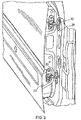
- an automotive hinge assembly (30) is substantially constructed from a door component (40) and a body component (60).
- the door component is configured with a mounting surface (41) and two pivot arms (42).
- Each pivot arm (42) contains a pivot axis hole (43).
- the door component (40) is structurally attached to a vehicle closure panel (27) via its mounting surface (41) using bolting, welding, bonding, riveting or similar fastening means.
- the body component (60) is configured with a mounting surface (61) and a pivot arm (62).
- the pivot arm (62) contains a pivot axis hole (63).
- the body component is structurally attached to a vehicle body structure (28) via its mounting surface (61) using bolting, welding, bonding, riveting or similar fastening means.
- the pivot axis hole (63) of the body component (60) is fitted with a pivot bushing (80) that contains an internal cylindrical bearing surface (81) and two opposing thrust flanges (82).
- a pivot pin (90) is configured with a central cylindrical pivot surface (91) and two knurled opposing cylindrical ends (92) each with a diameter less than the central cylindrical pivot surface diameter.
- the central cylindrical pivot surface (91) is adapted to freely rotate within the internal cylindrical bearing surface (81) of the pivot bushing and the two knurled opposing cylindrical ends (92) are adapted to be inserted and structurally connected to the to the door component (40) pivot axis holes (43) via riveting, staking or similar means of material upsetting. In this way the door component (40) and body component (60) are held in structural assembly but are free to rotate relatively to each other.
- the door component (40) is constructed from two press formed door angle brackets (46)(47) that are both configured with a mounting surface (41) and a pivot arm (42).
- the pivot arms (42) each contain a pivot axis hole (43).
- the pivot pin (40) therefore replaces the structural bridge normally required to create a single, unitary door component significantly reducing the amount of material required and associated cost.
- the body component (60) is constructed from two press formed body angle brackets (66)(67) that are both configured with a mounting surface (61) and a pivot arm (62).
- the pivot arms (62) each contain a pivot axis hole (63).
- the two body angle brackets (66)(67) are configured so that the two pivot arms (62) are arranged surface to surface and aligned via a semi-shear feature (68) fitted within a matching alignment hole (69).
- the semi-shear feature (68) is structurally connected within the alignment hole (69) via press fitting, welding, bonding, riveting, staking or similar means of material upsetting a single unitary body component (60) is created.
- the semi-shear (68) and alignment hole (69) are arranged so that the pivot axis holes (63) are in alignment.
- the pivot axis hole (63) is fitted with a pivot bushing (80) that contains an internal cylindrical bearing surface (81) and two opposing thrust flanges (82). In this way the two press formed body angle brackets (66)(67) create a single, unitary door component significantly reducing the amount of material required and associated cost in comparison to a single piece configuration.
- Fig. 10 illustrates the flat blank layout of both the press formed body angle brackets (66a)(67a) and the press formed door angle brackets (46a)(47a) of the present invention as well as the scrap material (58) associated with the stamping process.
- the present invention offers superior overall material efficiency and lower scrap content than the prior art configuration.
- a pair of hinge stop formations (70) are provided on the pivot arms (62) of the body angle brackets (66)(67) that are adapted to interact with a pair of hinge stop surfaces (50) provided on the pivot arms (42) or the door angle brackets (46)(47).
- the hinge stop surfaces (50) contact the hinge stop formations (70) and prevent further rotation.
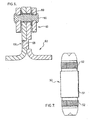
- Fig. 11 illustrates an alternative embodiment of the pivot pin (100) which does not form part of the present invention that incorporates two opposing cylindrical ends (102) that are configured without knurling.
- the pivot pin (100) is configured with tapered steps (105) between the larger diameter of the central cylindrical pivot surface (101) and the smaller diameters of two opposing cylindrical ends (102) that allow compensation for a range of body angle bracket material thickness.
- the steps are configured to be square and without taper so that the door angle brackets (46)(47) are pressed on to the two knurled opposing cylindrical ends (92) to a fixed distance defined by the steps.
- the two opposing thrust flanges (82) of the pivot bushing (80) can be under or over compressed resulting in inadequate structural assembly or poor relative rotational movement.
- the tapered steps (105) of the alternative embodiment allow the door angle brackets (46)(47) to be pressed onto the taper to a range of distances while allowing the riveting, staking or similar means of material upsetting to occur against a resistive base.
- the material interference between the two door angle brackets (46)(47) and the tapered steps (105) creates the structural connection between these components.
- FIG. 12 illustrates an alternative embodiment of the pivot pin (110) of the present invention that is configured with a fixed head (116) to facilitate single sided riveting.
- the pivot pin (110) is configured with a central cylindrical pivot surface (111) and two knurled opposing cylindrical ends (112)(113).
- the knurled cylindrical end (112) adjacent to the fixed head (116) is of a larger diameter than the central cylindrical pivot surface (111) and the knurled cylindrical end (113) at the opposing end of the pivot pin (110) is of a smaller diameter than the central cylindrical pivot surface diameter.
- the fixed head (116) is of a larger diameter than the knurled cylindrical ends (112)(113) and the central cylindrical pivot surface (111).
- Figs. 13 and 14 illustrate an alternative embodiment which does not form part of the present invention in that the pivot pin (190) is configured to facilitate ease of separation of the door component (140) and body component (160). This type of separation and reassembly is required in some vehicle assembly plants and is generally referred to as a lift-off process.
- Both the door component (140) and body component (160) are constructed in the same manner as the main embodiment of the present invention using two press formed door angle brackets (146)(147) and two press formed body angle brackets (166)(167).
- the pivot pin (190) is configured to be structurally connected to the two door angle brackets (146)(147) through a pivot bushing (180) and washer (184) via riveting, staking or similar means of material upsetting.
- the end of the pivot pin (190) opposite the washer and material upset is configured with a tapered feature (195) and threaded end (196) adapted to interface with a mating cylindrical pivot axis hole (163) in the body angle brackets (166).
- a tapered nut (187) is provided that threads onto the threaded end (196) and interfaces with the mating cylindrical pivot axis hole (163) in the body angle bracket (167) achieving correct structural assembly between the door component (140) and body component (160) while the bushing arrangement assures adequate rotational movement.
- a stop rivet (170) is adapted to structurally connected the two body angle brackets (166)(167) while also interacting with a hinge stop surface (150) provided on the door angle brackets (146)(147) so that when the door hinge assembly (130) is rotated to its full open position the hinge stop surfaces (150) contact the hinge stop formations (170) and prevent further rotation.
Landscapes
- Engineering & Computer Science (AREA)
- Mechanical Engineering (AREA)
- Hinges (AREA)
- Hinge Accessories (AREA)
- Body Structure For Vehicles (AREA)
Claims (8)
- Ensemble charnière automobile (30) comprenant :un composant de portière (40) construit à partir de première et seconde équerres de portière (46, 47) séparées formées à la presse, les première et seconde équerres de portière (46, 47) ayant chacune un bras de pivot (42) avec un trou de pivot (43) s'étendant à travers lui, les trous de pivot (43, 43) des première et seconde équerres de portière (46, 47) étant agencés en alignement l'un avec l'autre, le composant de portière (40) est adapté pour être monté sur un panneau de fermeture de véhicule (27) ;un composant de carrosserie (60) construit à partir de première et seconde équerres de carrosserie (66, 67) séparées formées à la presse, les première et seconde équerres de carrosserie (66, 67) ayant chacune un bras de pivot (62) avec une ouverture d'axe de pivot (63) s'étendant à travers lui etconfigurée pour accepter une douille de pivot (80), dans lequel les deux équerres de carrosserie (66)(67) sont configurées de sorte que les deux bras de pivot (62) soient agencés surface contre surface et alignés via un élément de semi-cisaillement (68) ajusté au sein d'un trou d'alignement (69) concordant, les ouvertures d'axe de pivot (63, 63) des première et seconde équerres de carrosserie (66, 67) étant agencées en alignement l'une avec l'autre, le composant de carrosserie (60) est adapté pour être monté sur une structure de carrosserie de véhicule (28) ;ladite douille de pivot (80) qui comprend une surface porteuse cylindrique interne (81) et deux brides d'appui (82) opposées ; etune goupille de pivot (90, 100, 110) pour maintenir les première et seconde équerres de portière (46, 47) et les première et seconde équerres de carrosserie (66, 67) en assemblage, la goupille de pivot s'étendant à travers les trous de pivot (43) et la douille de pivot (80) pour permettre au composant de portière (40) et au composant de carrosserie (60) de tourner l'un vis-à-vis de l'autre ;dans lequel la goupille de pivot (90, 100, 110) comprend :deux extrémités cylindriques opposées moletées en guise de première et seconde extrémités cylindriques (92, 92), les première et seconde équerres de portière (46, 47) étant appuyées sur les première et seconde extrémités cylindriques (92, 92), respectivement, et ;une surface de pivot cylindrique centrale (91, 101) positionnée entre les première et seconde extrémités cylindriques (92, 92), et ayant un diamètre central adapté pour permettre une rotation de la douille de pivot (80) autour d'elle ; etles première et seconde équerres de portière (46, 47) sont espacées et raccordées par la goupille de pivot (90, 100, 110), dans lequel les première et seconde extrémités cylindriques raccordent structurellement les première et seconde équerres de portière (46, 47) respectivement par refoulement de matériau.
- Ensemble charnière automobile selon la revendication 1, dans lequel la goupille de pivot (90, 100, 110) comprend en outre des première et seconde interfaces étagées ayant chacune un élément effilé (105) entre la surface de pivot cylindrique centrale (91, 101) et chacune des première et seconde extrémités cylindriques (92) pour permettre d'appuyer les première et seconde équerres de portière (46, 47) sur les premier et second éléments effilés (105) respectifs pour compenser des tolérances d'épaisseur des équerres de composant de carrosserie pendant le processus d'assemblage.
- Ensemble charnière automobile selon la revendication 2, dans lequel les première et seconde extrémités cylindriques de la goupille de pivot (90, 100, 110) comprennent chacune un diamètre qui est inférieur au diamètre central de la surface de pivot centrale (91, 101).
- Ensemble charnière automobile selon la revendication 1, dans lequel les première et seconde extrémités cylindriques de la goupille de pivot (90, 100, 110) comprennent un moletage et des premier et second diamètres respectivement, dans lequel le premier diamètre de la première extrémité est supérieur au diamètre central de la surface de pivot centrale (91, 101), dans lequel le second diamètre de la seconde extrémité est inférieur au diamètre central de la surface de pivot centrale (91, 101),
dans lequel la goupille de pivot (90, 100, 110) comprend en outre une tête fixe (116) positionnée adjacente à la première extrémité cylindrique, dans lequel la tête fixe (116) a un diamètre de tête supérieur au premier diamètre de la première extrémité cylindrique. - Ensemble charnière automobile selon la revendication 1, dans lequel les équerres de carrosserie (66, 67) formées à la presse sont raccordées structurellement via un élément de semi-cisaillement (68) et un trou d'alignement (69) concordant à l'aide d'un emmanchement à la presse, un soudage, une liaison, un rivetage ou un matage.
- Ensemble charnière automobile selon l'une quelconque des revendications 1 à 5, dans lequel une formation de butée de charnière (70) est prévue dans chacune des première et seconde équerres de carrosserie, une surface de butée de charnière (50) est prévue sur chacune des première et seconde équerres de portière, dans lequel les formations de butée de charnière (70) et les surfaces de butée de charnière (50) respectives interagissent pour empêcher structurellement l'ensemble charnière de tourner à sa position totalement ouverte.
- Système de fixation par charnière de portière de véhicule comprenant :un panneau de fermeture de véhicule (27) qui définit une surface de montage de composant de portière ;une structure de carrosserie de véhicule (28) qui définit une surface de montage de composant de carrosserie ;caractérisé en ce quele système de fixation par charnière de portière de véhicule comprend en outre l'ensemble charnière automobile de l'une quelconque des revendications 1 à 6,le composant de carrosserie (60) de l'ensemble charnière automobile est monté sur la surface de montage de composant de carrosserie, et le composant de portière (40) de l'ensemble charnière automobile est monté sur le panneau de fermeture de véhicule (27).
- Système de fixation par charnière de portière de véhicule selon la revendication 7, dans lequel le composant de portière (40) et le composant de carrosserie (60) sont montés sur le panneau de fermeture de véhicule (27) et la structure de carrosserie de véhicule (28) respectivement via un boulonnage, un rivetage, un soudage ou une liaison.
Priority Applications (1)
| Application Number | Priority Date | Filing Date | Title |
|---|---|---|---|
| EP20171885.5A EP3705671A1 (fr) | 2006-07-10 | 2007-02-12 | Charnière de portière automobile à construction de plusieurs pièces |
Applications Claiming Priority (3)
| Application Number | Priority Date | Filing Date | Title |
|---|---|---|---|
| CA002551642A CA2551642A1 (fr) | 2006-07-10 | 2006-07-10 | Ensemble de charnieres multipieces de portiere de vehicule automobile |
| PCT/CA2007/000199 WO2008006191A1 (fr) | 2006-07-10 | 2007-02-12 | Charnière de portière d'automobile à construction en pièces multiples |
| EP07710614.4A EP2038496B1 (fr) | 2006-07-10 | 2007-02-12 | Charniere de porte d'automobile a construction en pieces multiples |
Related Parent Applications (1)
| Application Number | Title | Priority Date | Filing Date |
|---|---|---|---|
| EP07710614.4A Division EP2038496B1 (fr) | 2006-07-10 | 2007-02-12 | Charniere de porte d'automobile a construction en pieces multiples |
Related Child Applications (2)
| Application Number | Title | Priority Date | Filing Date |
|---|---|---|---|
| EP20171885.5A Division-Into EP3705671A1 (fr) | 2006-07-10 | 2007-02-12 | Charnière de portière automobile à construction de plusieurs pièces |
| EP20171885.5A Division EP3705671A1 (fr) | 2006-07-10 | 2007-02-12 | Charnière de portière automobile à construction de plusieurs pièces |
Publications (3)
| Publication Number | Publication Date |
|---|---|
| EP2743434A2 EP2743434A2 (fr) | 2014-06-18 |
| EP2743434A3 EP2743434A3 (fr) | 2016-05-25 |
| EP2743434B1 true EP2743434B1 (fr) | 2021-08-11 |
Family
ID=38920789
Family Applications (3)
| Application Number | Title | Priority Date | Filing Date |
|---|---|---|---|
| EP20171885.5A Ceased EP3705671A1 (fr) | 2006-07-10 | 2007-02-12 | Charnière de portière automobile à construction de plusieurs pièces |
| EP14159033.1A Active EP2743434B1 (fr) | 2006-07-10 | 2007-02-12 | Charnière de portière automobile à construction de plusieurs pièces |
| EP07710614.4A Active EP2038496B1 (fr) | 2006-07-10 | 2007-02-12 | Charniere de porte d'automobile a construction en pieces multiples |
Family Applications Before (1)
| Application Number | Title | Priority Date | Filing Date |
|---|---|---|---|
| EP20171885.5A Ceased EP3705671A1 (fr) | 2006-07-10 | 2007-02-12 | Charnière de portière automobile à construction de plusieurs pièces |
Family Applications After (1)
| Application Number | Title | Priority Date | Filing Date |
|---|---|---|---|
| EP07710614.4A Active EP2038496B1 (fr) | 2006-07-10 | 2007-02-12 | Charniere de porte d'automobile a construction en pieces multiples |
Country Status (10)
| Country | Link |
|---|---|
| US (4) | US9863175B2 (fr) |
| EP (3) | EP3705671A1 (fr) |
| JP (2) | JP5286260B2 (fr) |
| KR (1) | KR101461679B1 (fr) |
| CN (2) | CN104727675A (fr) |
| AU (1) | AU2007272240B2 (fr) |
| BR (1) | BRPI0702925A2 (fr) |
| CA (2) | CA2551642A1 (fr) |
| ES (2) | ES2895363T3 (fr) |
| WO (1) | WO2008006191A1 (fr) |
Families Citing this family (40)
| Publication number | Priority date | Publication date | Assignee | Title |
|---|---|---|---|---|
| CA2551642A1 (fr) * | 2006-07-10 | 2008-01-10 | Multimatic Inc. | Ensemble de charnieres multipieces de portiere de vehicule automobile |
| DE102006050662B3 (de) * | 2006-10-24 | 2008-01-31 | Automotive Group Ise Innomotive Systems Europe Gmbh | Kraftfahrzeugtürscharnier |
| US20150023387A1 (en) * | 2008-03-31 | 2015-01-22 | Jfe Steel Corporation | Steel plate quality assurance system and equipment thereof |
| US8156611B2 (en) | 2008-08-01 | 2012-04-17 | Ford Global Technologies, Llc | Lift-off door hinge |
| CA2773581C (fr) * | 2009-09-10 | 2014-02-25 | Toyota Shatai Kabushiki Kaisha | Charniere pour porte de vehicule |
| US20130111703A1 (en) * | 2010-05-03 | 2013-05-09 | M&C Corporation | Adjustable pivot deck lid |
| CN101967924A (zh) * | 2010-11-17 | 2011-02-09 | 重庆长安汽车股份有限公司 | 一种汽车前罩铰链 |
| DE102012208024B4 (de) * | 2012-05-14 | 2020-03-19 | Bayerische Motoren Werke Aktiengesellschaft | Scharnierlager, insbesondere für eine Tür oder Klappe eines Kraftfahrzeugs |
| JP6160039B2 (ja) | 2012-08-10 | 2017-07-12 | スズキ株式会社 | ヒンジ装置 |
| JP6330235B2 (ja) * | 2013-07-26 | 2018-05-30 | 三井金属アクト株式会社 | 車両用ドアヒンジ |
| CN105089263A (zh) * | 2014-05-22 | 2015-11-25 | 深圳市特辰科技股份有限公司 | 多孔合页组件及施工平台 |
| US10604991B2 (en) * | 2014-06-26 | 2020-03-31 | Sorrel Quarters, Llc | Overhead door and frame assembly |
| CN105133978A (zh) * | 2015-09-23 | 2015-12-09 | 无锡市中捷减震器有限公司 | 连接车门与车身的铰链 |
| US10184280B2 (en) * | 2016-06-02 | 2019-01-22 | Flex-N-Gate Advanced Product Development, Llc. | Automotive door hinge |
| US10315707B2 (en) * | 2017-07-27 | 2019-06-11 | Cnh Industrial America Llc | Engine hood mounting system |
| JP6656220B2 (ja) * | 2017-12-22 | 2020-03-04 | 本田技研工業株式会社 | ヒンジ機構 |
| JP7106858B2 (ja) * | 2017-12-26 | 2022-07-27 | トヨタ自動車株式会社 | 車両用ドアヒンジ構造 |
| CN108160834A (zh) * | 2018-02-09 | 2018-06-15 | 烽火通信科技股份有限公司 | 高硬度不锈钢铰链的多段铆压方法 |
| JP7047237B2 (ja) * | 2018-03-15 | 2022-04-05 | 三井金属アクト株式会社 | 自動車用ドアヒンジの製造方法及び自動車 |
| WO2019176777A1 (fr) * | 2018-03-15 | 2019-09-19 | 三井金属アクト株式会社 | Appareil de charnière de porte d'automobile |
| JP6957798B2 (ja) * | 2018-03-15 | 2021-11-02 | 三井金属アクト株式会社 | 自動車用ドアヒンジ装置 |
| CN111801479B (zh) * | 2018-03-15 | 2022-07-29 | 三井金属爱科特株式会社 | 汽车用门铰链装置 |
| KR102115335B1 (ko) * | 2018-05-31 | 2020-05-26 | 주식회사다스 | 시트 레일의 록킹 장치 |
| CN109083527B (zh) * | 2018-09-18 | 2021-05-04 | 重庆长安汽车股份有限公司 | 自限位车门铰链及汽车 |
| US20220042362A1 (en) * | 2019-01-18 | 2022-02-10 | Warren Industries Ltd. | Vehicular door hinge with folded sheet metal component |
| US10626646B1 (en) | 2019-05-21 | 2020-04-21 | Ford Global Technologies, Llc | Self-contained door hinge release |
| DE102019115563B3 (de) * | 2019-06-07 | 2020-04-23 | Edscha Engineering Gmbh | Fahrzeugscharnier und Verfahren zur Herstellung einer Scharnierhälfte für ein Fahrzeugscharnier |
| EP3771791B1 (fr) * | 2019-07-29 | 2022-01-19 | C.R.F. Società Consortile per Azioni | Charnière de pièce mobile de véhicule à moteur |
| US20210145213A1 (en) * | 2019-11-20 | 2021-05-20 | The Big Green Egg, Inc. | Universal Bracket Assembly for Grill Apparatuses |
| CN111021861A (zh) * | 2019-12-31 | 2020-04-17 | 银隆新能源股份有限公司 | 侧舱门安装方法 |
| CN113137147A (zh) * | 2020-01-16 | 2021-07-20 | 尼特固有限公司 | 车辆用的车门铰链结构 |
| JP2021113039A (ja) * | 2020-01-16 | 2021-08-05 | 株式会社ニイテック | 車両用ドアヒンジ構造 |
| AT523753B1 (de) * | 2020-05-07 | 2023-06-15 | Blum Gmbh Julius | Möbelbeschlag |
| CN111661174A (zh) * | 2020-06-08 | 2020-09-15 | 东风汽车股份有限公司 | 一种载货汽车车厢铰链减震降噪结构及其装配方法 |
| AT524392A1 (de) * | 2020-11-12 | 2022-05-15 | Blum Gmbh Julius | Möbelbeschlag mit mindestens einem Drehhebel und mindestens einem Lagerstift |
| USD1046596S1 (en) * | 2021-07-02 | 2024-10-15 | SROOC Holdings, LLC | Hinge for a utility vehicle door |
| CN216960402U (zh) * | 2021-11-03 | 2022-07-12 | 华为技术有限公司 | 阻尼销及机柜 |
| WO2025096768A1 (fr) * | 2023-11-02 | 2025-05-08 | Multimatic Patentco Llc | Système de charnière d'alignement de portière |
| CN119705639A (zh) * | 2024-11-29 | 2025-03-28 | 东风汽车集团股份有限公司 | 一种车身前机舱上纵梁结构及其连接结构 |
| CN119426461B (zh) * | 2025-01-13 | 2025-06-17 | 苏州宝昱来智能装备有限公司 | 一种冲压模具快速成型装置 |
Citations (1)
| Publication number | Priority date | Publication date | Assignee | Title |
|---|---|---|---|---|
| US3141662A (en) * | 1957-10-02 | 1964-07-21 | Anderson Co | Motion-transmitting device |
Family Cites Families (47)
| Publication number | Priority date | Publication date | Assignee | Title |
|---|---|---|---|---|
| US1164857A (en) | 1914-07-23 | 1915-12-21 | Stanlly Works | Hinge for vehicle-doors. |
| US1582701A (en) * | 1925-04-16 | 1926-04-27 | Soss Joseph | Hinge |
| US1941348A (en) * | 1931-11-07 | 1933-12-26 | Curtiss Aeroplane & Motor Co | Joint fitting |
| US2200317A (en) * | 1937-08-02 | 1940-05-14 | Atwood Vacuum Machine Co | Hinge |
| US2585836A (en) * | 1946-12-09 | 1952-02-12 | Nat Brass Co | Hinge |
| JPS5834213Y2 (ja) * | 1974-09-11 | 1983-08-01 | ミヤザキ アキオ | オオガタレイゾウコニ オケル フロントドアノ カイヘイシジキコウ |
| JPS5137359A (ja) | 1974-09-25 | 1976-03-29 | Katayama Kogyo Kk | Beroozunoseizohoho |
| JPS5519813Y2 (fr) * | 1975-10-07 | 1980-05-12 | ||
| JPS5249432A (en) | 1975-10-17 | 1977-04-20 | Sanyo Electric Co | Charging device for storage battery |
| JPS571259A (en) | 1980-06-03 | 1982-01-06 | Matsushita Electric Ind Co Ltd | Manufacture of semiconductor device |
| JPS571259U (fr) * | 1980-06-04 | 1982-01-06 | ||
| GB2077348B (en) * | 1980-06-07 | 1984-06-13 | Ihw Eng Ltd | Method of forming a hinge bracket |
| GB2099070B (en) * | 1981-05-14 | 1985-07-03 | Ihw Eng Ltd | Vehicle door hinge |
| SE453846B (sv) * | 1983-09-19 | 1988-03-07 | Scharwaechter Gmbh Co Kg | Dorrgangjern for motorfordon |
| JPS6153976A (ja) * | 1984-08-22 | 1986-03-18 | 日産自動車株式会社 | 車両用ドアヒンジ |
| JPS63156183A (ja) | 1986-12-17 | 1988-06-29 | ダイハツ工業株式会社 | 建付け再現ヒンジ構造およびこれによる建付け再現方法 |
| DE8703236U1 (de) * | 1987-03-03 | 1987-05-27 | Ed. Scharwächter GmbH + Co KG, 42855 Remscheid | Aushängbares Flügelscharnier |
| JPS6471981A (en) | 1987-09-09 | 1989-03-16 | Daihatsu Motor Co Ltd | Door hinge for automobile |
| JPH0171981U (fr) | 1987-11-02 | 1989-05-15 | ||
| EP0382170B1 (fr) * | 1989-02-07 | 1995-01-18 | Ohi Seisakusho Co., Ltd. | Douille déformable plastiquement pour utilisation dans une charnière de véhicule et méthode pour produire de telles douilles |
| JPH0633178Y2 (ja) * | 1989-02-07 | 1994-08-31 | 株式会社大井製作所 | 自動車用ドアヒンジ |
| JPH0735076Y2 (ja) * | 1989-11-10 | 1995-08-09 | 株式会社ニイテック | 自動車用ドアヒンジ |
| JPH0439266A (ja) | 1990-06-01 | 1992-02-10 | Takatori Haitetsuku:Kk | 靴下の折り畳み方法と装置 |
| JPH0747580Y2 (ja) * | 1990-08-01 | 1995-11-01 | 日本発条株式会社 | 摩擦ロック装置 |
| JP2614678B2 (ja) * | 1991-10-23 | 1997-05-28 | 株式会社大井製作所 | ヒンジ装置およびその製造方法 |
| FR2719867B1 (fr) * | 1994-05-16 | 1996-08-02 | Coutier Moulage Gen Ind | Ensemble articulé notamment pour arrêt de porte de véhicule automobile. |
| US5577295A (en) * | 1994-09-27 | 1996-11-26 | Chrysler Corporation | Three diameter hinge pin |
| US5590441A (en) * | 1995-02-27 | 1997-01-07 | General Motors Corporation | Lift-off door hinge |
| US5682646A (en) * | 1996-05-13 | 1997-11-04 | Chrysler Corporation | Threaded removable vehicle door hinge pin |
| DE19724202C1 (de) | 1997-06-09 | 1998-09-03 | Scharwaechter Gmbh Co Kg | Aushängbares Kraftwagentürscharnier |
| JP3411804B2 (ja) | 1997-12-05 | 2003-06-03 | 水島プレス工業株式会社 | 車両用ヒンジ構造 |
| JP2002511545A (ja) * | 1998-04-09 | 2002-04-16 | エー・デー・シャルベヒテル・ゲゼルシャフト・ミット・ベシュレンクテル・ハフツング | ドアヒンジと構造的に組合されるドアストップ |
| DE19835572A1 (de) | 1998-08-06 | 2000-02-10 | Scharwaechter Ed Gmbh | Anschlußeinrichtung zur Verbindung eines Türfeststellers mit einem Kraftwagentürscharnier |
| KR100449969B1 (ko) * | 1998-12-21 | 2004-09-24 | 멀티메틱 인코포레이티드 | 차량용 도어 지지 버튼 |
| ES2201814T3 (es) | 1998-12-21 | 2004-03-16 | Multimatic Inc. | Boton de soporte de puerta de vehiculo. |
| JP3966633B2 (ja) | 1998-12-24 | 2007-08-29 | 理研化機工業株式会社 | ヒンジ及びその製造方法 |
| US6199448B1 (en) * | 1999-11-09 | 2001-03-13 | Trw Inc. | Steering attachment with tapered pin and fastener |
| US6453510B1 (en) * | 2000-09-21 | 2002-09-24 | Mansfield Assemblies Co. | Single link dual-contact point hinge assembly |
| CA2348323C (fr) * | 2001-05-24 | 2006-02-14 | Multimatic Inc. | Charniere de portiere automobile a composant amovible permettant un remontage structural |
| KR100798293B1 (ko) * | 2001-08-02 | 2008-01-28 | 멀티메틱 인코포레이티드 | 피봇이 구조적으로 통합된 자동차 도어힌지 |
| US6718596B2 (en) * | 2002-06-25 | 2004-04-13 | Ford Global Technologies, Llc | Reversible door hinge |
| DE20214356U1 (de) | 2002-09-16 | 2004-02-26 | Ise Innomotive Systems Europe Gmbh | Verbindung zwischen einer Scheibe und einer Stange |
| JP3861827B2 (ja) | 2003-02-25 | 2006-12-27 | 松下電工株式会社 | 蝶番の台座高さ調整スペーサ |
| DE102004012006B3 (de) * | 2004-03-10 | 2005-06-30 | Ise Innomotive Systems Europe Gmbh | Türscharnier für Kraftfahrzeuge |
| CZ14639U1 (cs) * | 2004-05-28 | 2004-08-24 | Edschaábohemiaás@Ár@Áo | Závěsné zařízení dveří automobilu |
| WO2006081417A1 (fr) * | 2005-01-27 | 2006-08-03 | Johnson Controls Technology Company | Installation sans outil d'un dossier de siege pliant |
| CA2551642A1 (fr) * | 2006-07-10 | 2008-01-10 | Multimatic Inc. | Ensemble de charnieres multipieces de portiere de vehicule automobile |
-
2006
- 2006-07-10 CA CA002551642A patent/CA2551642A1/fr not_active Abandoned
-
2007
- 2007-02-12 CN CN201510054885.8A patent/CN104727675A/zh active Pending
- 2007-02-12 CN CNA2007800012098A patent/CN101356333A/zh active Pending
- 2007-02-12 ES ES14159033T patent/ES2895363T3/es active Active
- 2007-02-12 ES ES07710614.4T patent/ES2469618T3/es active Active
- 2007-02-12 KR KR1020087014032A patent/KR101461679B1/ko active Active
- 2007-02-12 BR BRPI0702925-0A patent/BRPI0702925A2/pt active IP Right Grant
- 2007-02-12 WO PCT/CA2007/000199 patent/WO2008006191A1/fr not_active Ceased
- 2007-02-12 EP EP20171885.5A patent/EP3705671A1/fr not_active Ceased
- 2007-02-12 EP EP14159033.1A patent/EP2743434B1/fr active Active
- 2007-02-12 CA CA2623959A patent/CA2623959C/fr active Active
- 2007-02-12 EP EP07710614.4A patent/EP2038496B1/fr active Active
- 2007-02-12 JP JP2009518690A patent/JP5286260B2/ja active Active
- 2007-02-12 AU AU2007272240A patent/AU2007272240B2/en not_active Ceased
- 2007-02-12 US US12/091,384 patent/US9863175B2/en active Active
-
2013
- 2013-01-10 JP JP2013002764A patent/JP5479619B2/ja active Active
-
2017
- 2017-11-29 US US15/825,427 patent/US10100563B2/en active Active
-
2018
- 2018-10-15 US US16/160,458 patent/US20190048635A1/en not_active Abandoned
-
2020
- 2020-06-03 US US16/891,435 patent/US20200362610A1/en not_active Abandoned
Patent Citations (1)
| Publication number | Priority date | Publication date | Assignee | Title |
|---|---|---|---|---|
| US3141662A (en) * | 1957-10-02 | 1964-07-21 | Anderson Co | Motion-transmitting device |
Also Published As
| Publication number | Publication date |
|---|---|
| CN104727675A (zh) | 2015-06-24 |
| EP2038496A1 (fr) | 2009-03-25 |
| US20080295290A1 (en) | 2008-12-04 |
| CA2623959C (fr) | 2013-10-22 |
| US20190048635A1 (en) | 2019-02-14 |
| KR20090060210A (ko) | 2009-06-11 |
| JP5286260B2 (ja) | 2013-09-11 |
| BRPI0702925A2 (pt) | 2011-03-22 |
| AU2007272240B2 (en) | 2013-06-13 |
| CA2551642A1 (fr) | 2008-01-10 |
| AU2007272240A1 (en) | 2008-01-17 |
| US10100563B2 (en) | 2018-10-16 |
| EP2743434A2 (fr) | 2014-06-18 |
| WO2008006191A1 (fr) | 2008-01-17 |
| JP2009542942A (ja) | 2009-12-03 |
| US9863175B2 (en) | 2018-01-09 |
| JP2013144924A (ja) | 2013-07-25 |
| CN101356333A (zh) | 2009-01-28 |
| JP5479619B2 (ja) | 2014-04-23 |
| ES2469618T3 (es) | 2014-06-18 |
| US20200362610A1 (en) | 2020-11-19 |
| KR101461679B1 (ko) | 2014-11-13 |
| EP2038496A4 (fr) | 2012-10-17 |
| CA2623959A1 (fr) | 2008-01-17 |
| ES2895363T3 (es) | 2022-02-21 |
| EP2743434A3 (fr) | 2016-05-25 |
| US20180100337A1 (en) | 2018-04-12 |
| AU2007272240A2 (en) | 2010-04-01 |
| EP2038496B1 (fr) | 2014-04-02 |
| EP3705671A1 (fr) | 2020-09-09 |
Similar Documents
| Publication | Publication Date | Title |
|---|---|---|
| EP2743434B1 (fr) | Charnière de portière automobile à construction de plusieurs pièces | |
| US8156611B2 (en) | Lift-off door hinge | |
| US7536748B2 (en) | Gooseneck hinge assembly for vehicles | |
| US10184280B2 (en) | Automotive door hinge | |
| US5611114A (en) | High strength, dual action hinge | |
| US5452501A (en) | Hinge and check assembly | |
| US6728993B1 (en) | Structure for pivotally supporting check plate of door checker | |
| CN115698456B (zh) | 具有集成式门限位件的汽车提离式铰链 | |
| JPH08193456A (ja) | ドア固定装置と一体構造の自動車ドア用ドア蝶番 | |
| WO2007126342A1 (fr) | Pilier pour suspension d'une porte de véhicule articulée | |
| US8109848B2 (en) | Pivotal connection of a bicycle derailleur | |
| JP3411804B2 (ja) | 車両用ヒンジ構造 | |
| JP2008512586A (ja) | 自動車のドアヒンジ補強具 | |
| CN219953025U (zh) | 一种前机舱盖铰链结构 | |
| KR0155208B1 (ko) | 자동차의 도어힌지 | |
| JPH08128251A (ja) | 自動車用ドアヒンジ | |
| BRPI0702925B1 (pt) | Automatic hinged assembly |
Legal Events
| Date | Code | Title | Description |
|---|---|---|---|
| PUAI | Public reference made under article 153(3) epc to a published international application that has entered the european phase |
Free format text: ORIGINAL CODE: 0009012 |
|
| 17P | Request for examination filed |
Effective date: 20140312 |
|
| AC | Divisional application: reference to earlier application |
Ref document number: 2038496 Country of ref document: EP Kind code of ref document: P |
|
| AK | Designated contracting states |
Kind code of ref document: A2 Designated state(s): AT BE BG CH CY CZ DE DK EE ES FI FR GB GR HU IE IS IT LI LT LU LV MC NL PL PT RO SE SI SK TR |
|
| PUAL | Search report despatched |
Free format text: ORIGINAL CODE: 0009013 |
|
| AK | Designated contracting states |
Kind code of ref document: A3 Designated state(s): AT BE BG CH CY CZ DE DK EE ES FI FR GB GR HU IE IS IT LI LT LU LV MC NL PL PT RO SE SI SK TR |
|
| RIC1 | Information provided on ipc code assigned before grant |
Ipc: E05D 5/10 20060101ALI20160420BHEP Ipc: E05D 3/02 20060101AFI20160420BHEP Ipc: E05D 5/02 20060101ALI20160420BHEP Ipc: E05D 5/12 20060101ALI20160420BHEP Ipc: E05D 11/06 20060101ALI20160420BHEP |
|
| STAA | Information on the status of an ep patent application or granted ep patent |
Free format text: STATUS: REQUEST FOR EXAMINATION WAS MADE |
|
| R17P | Request for examination filed (corrected) |
Effective date: 20161118 |
|
| RBV | Designated contracting states (corrected) |
Designated state(s): AT BE BG CH CY CZ DE DK EE ES FI FR GB GR HU IE IS IT LI LT LU LV MC NL PL PT RO SE SI SK TR |
|
| STAA | Information on the status of an ep patent application or granted ep patent |
Free format text: STATUS: EXAMINATION IS IN PROGRESS |
|
| 17Q | First examination report despatched |
Effective date: 20181022 |
|
| GRAP | Despatch of communication of intention to grant a patent |
Free format text: ORIGINAL CODE: EPIDOSNIGR1 |
|
| STAA | Information on the status of an ep patent application or granted ep patent |
Free format text: STATUS: GRANT OF PATENT IS INTENDED |
|
| INTG | Intention to grant announced |
Effective date: 20210317 |
|
| GRAS | Grant fee paid |
Free format text: ORIGINAL CODE: EPIDOSNIGR3 |
|
| GRAA | (expected) grant |
Free format text: ORIGINAL CODE: 0009210 |
|
| STAA | Information on the status of an ep patent application or granted ep patent |
Free format text: STATUS: THE PATENT HAS BEEN GRANTED |
|
| RIN1 | Information on inventor provided before grant (corrected) |
Inventor name: WORDEN, SCOTT Inventor name: LAD, PRAD Inventor name: BANJONGPANITH, PASITH Inventor name: NG, CHEAN WANG Inventor name: GRUBER, RUDOLF Inventor name: MURRAY, ROBERT JOHN |
|
| AC | Divisional application: reference to earlier application |
Ref document number: 2038496 Country of ref document: EP Kind code of ref document: P |
|
| AK | Designated contracting states |
Kind code of ref document: B1 Designated state(s): AT BE BG CH CY CZ DE DK EE ES FI FR GB GR HU IE IS IT LI LT LU LV MC NL PL PT RO SE SI SK TR |
|
| REG | Reference to a national code |
Ref country code: GB Ref legal event code: FG4D |
|
| REG | Reference to a national code |
Ref country code: CH Ref legal event code: EP |
|
| REG | Reference to a national code |
Ref country code: DE Ref legal event code: R096 Ref document number: 602007061263 Country of ref document: DE |
|
| REG | Reference to a national code |
Ref country code: IE Ref legal event code: FG4D Ref country code: AT Ref legal event code: REF Ref document number: 1419557 Country of ref document: AT Kind code of ref document: T Effective date: 20210915 |
|
| REG | Reference to a national code |
Ref country code: SE Ref legal event code: TRGR |
|
| REG | Reference to a national code |
Ref country code: LT Ref legal event code: MG9D |
|
| REG | Reference to a national code |
Ref country code: NL Ref legal event code: MP Effective date: 20210811 |
|
| REG | Reference to a national code |
Ref country code: AT Ref legal event code: MK05 Ref document number: 1419557 Country of ref document: AT Kind code of ref document: T Effective date: 20210811 |
|
| PG25 | Lapsed in a contracting state [announced via postgrant information from national office to epo] |
Ref country code: PT Free format text: LAPSE BECAUSE OF FAILURE TO SUBMIT A TRANSLATION OF THE DESCRIPTION OR TO PAY THE FEE WITHIN THE PRESCRIBED TIME-LIMIT Effective date: 20211213 Ref country code: FI Free format text: LAPSE BECAUSE OF FAILURE TO SUBMIT A TRANSLATION OF THE DESCRIPTION OR TO PAY THE FEE WITHIN THE PRESCRIBED TIME-LIMIT Effective date: 20210811 Ref country code: AT Free format text: LAPSE BECAUSE OF FAILURE TO SUBMIT A TRANSLATION OF THE DESCRIPTION OR TO PAY THE FEE WITHIN THE PRESCRIBED TIME-LIMIT Effective date: 20210811 Ref country code: BG Free format text: LAPSE BECAUSE OF FAILURE TO SUBMIT A TRANSLATION OF THE DESCRIPTION OR TO PAY THE FEE WITHIN THE PRESCRIBED TIME-LIMIT Effective date: 20211111 Ref country code: LT Free format text: LAPSE BECAUSE OF FAILURE TO SUBMIT A TRANSLATION OF THE DESCRIPTION OR TO PAY THE FEE WITHIN THE PRESCRIBED TIME-LIMIT Effective date: 20210811 |
|
| REG | Reference to a national code |
Ref country code: ES Ref legal event code: FG2A Ref document number: 2895363 Country of ref document: ES Kind code of ref document: T3 Effective date: 20220221 |
|
| PG25 | Lapsed in a contracting state [announced via postgrant information from national office to epo] |
Ref country code: PL Free format text: LAPSE BECAUSE OF FAILURE TO SUBMIT A TRANSLATION OF THE DESCRIPTION OR TO PAY THE FEE WITHIN THE PRESCRIBED TIME-LIMIT Effective date: 20210811 Ref country code: LV Free format text: LAPSE BECAUSE OF FAILURE TO SUBMIT A TRANSLATION OF THE DESCRIPTION OR TO PAY THE FEE WITHIN THE PRESCRIBED TIME-LIMIT Effective date: 20210811 Ref country code: GR Free format text: LAPSE BECAUSE OF FAILURE TO SUBMIT A TRANSLATION OF THE DESCRIPTION OR TO PAY THE FEE WITHIN THE PRESCRIBED TIME-LIMIT Effective date: 20211112 |
|
| PG25 | Lapsed in a contracting state [announced via postgrant information from national office to epo] |
Ref country code: NL Free format text: LAPSE BECAUSE OF FAILURE TO SUBMIT A TRANSLATION OF THE DESCRIPTION OR TO PAY THE FEE WITHIN THE PRESCRIBED TIME-LIMIT Effective date: 20210811 |
|
| PG25 | Lapsed in a contracting state [announced via postgrant information from national office to epo] |
Ref country code: DK Free format text: LAPSE BECAUSE OF FAILURE TO SUBMIT A TRANSLATION OF THE DESCRIPTION OR TO PAY THE FEE WITHIN THE PRESCRIBED TIME-LIMIT Effective date: 20210811 |
|
| REG | Reference to a national code |
Ref country code: DE Ref legal event code: R097 Ref document number: 602007061263 Country of ref document: DE |
|
| PG25 | Lapsed in a contracting state [announced via postgrant information from national office to epo] |
Ref country code: SK Free format text: LAPSE BECAUSE OF FAILURE TO SUBMIT A TRANSLATION OF THE DESCRIPTION OR TO PAY THE FEE WITHIN THE PRESCRIBED TIME-LIMIT Effective date: 20210811 Ref country code: RO Free format text: LAPSE BECAUSE OF FAILURE TO SUBMIT A TRANSLATION OF THE DESCRIPTION OR TO PAY THE FEE WITHIN THE PRESCRIBED TIME-LIMIT Effective date: 20210811 Ref country code: EE Free format text: LAPSE BECAUSE OF FAILURE TO SUBMIT A TRANSLATION OF THE DESCRIPTION OR TO PAY THE FEE WITHIN THE PRESCRIBED TIME-LIMIT Effective date: 20210811 Ref country code: CZ Free format text: LAPSE BECAUSE OF FAILURE TO SUBMIT A TRANSLATION OF THE DESCRIPTION OR TO PAY THE FEE WITHIN THE PRESCRIBED TIME-LIMIT Effective date: 20210811 |
|
| PLBE | No opposition filed within time limit |
Free format text: ORIGINAL CODE: 0009261 |
|
| STAA | Information on the status of an ep patent application or granted ep patent |
Free format text: STATUS: NO OPPOSITION FILED WITHIN TIME LIMIT |
|
| 26N | No opposition filed |
Effective date: 20220512 |
|
| PG25 | Lapsed in a contracting state [announced via postgrant information from national office to epo] |
Ref country code: SI Free format text: LAPSE BECAUSE OF FAILURE TO SUBMIT A TRANSLATION OF THE DESCRIPTION OR TO PAY THE FEE WITHIN THE PRESCRIBED TIME-LIMIT Effective date: 20210811 |
|
| PG25 | Lapsed in a contracting state [announced via postgrant information from national office to epo] |
Ref country code: MC Free format text: LAPSE BECAUSE OF FAILURE TO SUBMIT A TRANSLATION OF THE DESCRIPTION OR TO PAY THE FEE WITHIN THE PRESCRIBED TIME-LIMIT Effective date: 20210811 |
|
| REG | Reference to a national code |
Ref country code: CH Ref legal event code: PL |
|
| REG | Reference to a national code |
Ref country code: BE Ref legal event code: MM Effective date: 20220228 |
|
| PG25 | Lapsed in a contracting state [announced via postgrant information from national office to epo] |
Ref country code: LU Free format text: LAPSE BECAUSE OF NON-PAYMENT OF DUE FEES Effective date: 20220212 |
|
| PG25 | Lapsed in a contracting state [announced via postgrant information from national office to epo] |
Ref country code: LI Free format text: LAPSE BECAUSE OF NON-PAYMENT OF DUE FEES Effective date: 20220228 Ref country code: IE Free format text: LAPSE BECAUSE OF NON-PAYMENT OF DUE FEES Effective date: 20220212 Ref country code: CH Free format text: LAPSE BECAUSE OF NON-PAYMENT OF DUE FEES Effective date: 20220228 |
|
| PG25 | Lapsed in a contracting state [announced via postgrant information from national office to epo] |
Ref country code: BE Free format text: LAPSE BECAUSE OF NON-PAYMENT OF DUE FEES Effective date: 20220228 |
|
| P01 | Opt-out of the competence of the unified patent court (upc) registered |
Effective date: 20230505 |
|
| PG25 | Lapsed in a contracting state [announced via postgrant information from national office to epo] |
Ref country code: HU Free format text: LAPSE BECAUSE OF FAILURE TO SUBMIT A TRANSLATION OF THE DESCRIPTION OR TO PAY THE FEE WITHIN THE PRESCRIBED TIME-LIMIT; INVALID AB INITIO Effective date: 20070212 |
|
| PG25 | Lapsed in a contracting state [announced via postgrant information from national office to epo] |
Ref country code: CY Free format text: LAPSE BECAUSE OF FAILURE TO SUBMIT A TRANSLATION OF THE DESCRIPTION OR TO PAY THE FEE WITHIN THE PRESCRIBED TIME-LIMIT Effective date: 20210811 |
|
| PGFP | Annual fee paid to national office [announced via postgrant information from national office to epo] |
Ref country code: FR Payment date: 20251208 Year of fee payment: 20 |
|
| PGFP | Annual fee paid to national office [announced via postgrant information from national office to epo] |
Ref country code: SE Payment date: 20251210 Year of fee payment: 20 |
|
| PGFP | Annual fee paid to national office [announced via postgrant information from national office to epo] |
Ref country code: GB Payment date: 20260106 Year of fee payment: 20 |
|
| PGFP | Annual fee paid to national office [announced via postgrant information from national office to epo] |
Ref country code: ES Payment date: 20260310 Year of fee payment: 20 |
|
| PGFP | Annual fee paid to national office [announced via postgrant information from national office to epo] |
Ref country code: DE Payment date: 20251216 Year of fee payment: 20 |
|
| PGFP | Annual fee paid to national office [announced via postgrant information from national office to epo] |
Ref country code: IT Payment date: 20260122 Year of fee payment: 20 |
|
| PGFP | Annual fee paid to national office [announced via postgrant information from national office to epo] |
Ref country code: TR Payment date: 20260209 Year of fee payment: 20 |