EP2746483A1 - Dispositif d'amortisseur d'oscillations - Google Patents
Dispositif d'amortisseur d'oscillations Download PDFInfo
- Publication number
- EP2746483A1 EP2746483A1 EP20120008532 EP12008532A EP2746483A1 EP 2746483 A1 EP2746483 A1 EP 2746483A1 EP 20120008532 EP20120008532 EP 20120008532 EP 12008532 A EP12008532 A EP 12008532A EP 2746483 A1 EP2746483 A1 EP 2746483A1
- Authority
- EP
- European Patent Office
- Prior art keywords
- rail
- arrangement
- absorber mass
- wheel
- mass
- Prior art date
- Legal status (The legal status is an assumption and is not a legal conclusion. Google has not performed a legal analysis and makes no representation as to the accuracy of the status listed.)
- Granted
Links
Images



Classifications
-
- F—MECHANICAL ENGINEERING; LIGHTING; HEATING; WEAPONS; BLASTING
- F16—ENGINEERING ELEMENTS AND UNITS; GENERAL MEASURES FOR PRODUCING AND MAINTAINING EFFECTIVE FUNCTIONING OF MACHINES OR INSTALLATIONS; THERMAL INSULATION IN GENERAL
- F16F—SPRINGS; SHOCK-ABSORBERS; MEANS FOR DAMPING VIBRATION
- F16F7/00—Vibration-dampers; Shock-absorbers
- F16F7/10—Vibration-dampers; Shock-absorbers using inertia effect
- F16F7/104—Vibration-dampers; Shock-absorbers using inertia effect the inertia member being resiliently mounted
-
- E—FIXED CONSTRUCTIONS
- E04—BUILDING
- E04H—BUILDINGS OR LIKE STRUCTURES FOR PARTICULAR PURPOSES; SWIMMING OR SPLASH BATHS OR POOLS; MASTS; FENCING; TENTS OR CANOPIES, IN GENERAL
- E04H9/00—Buildings, groups of buildings or shelters adapted to withstand or provide protection against abnormal external influences, e.g. war-like action, earthquake or extreme climate
- E04H9/02—Buildings, groups of buildings or shelters adapted to withstand or provide protection against abnormal external influences, e.g. war-like action, earthquake or extreme climate withstanding earthquake or sinking of ground
- E04H9/021—Bearing, supporting or connecting constructions specially adapted for such buildings
- E04H9/0215—Bearing, supporting or connecting constructions specially adapted for such buildings involving active or passive dynamic mass damping systems
-
- F—MECHANICAL ENGINEERING; LIGHTING; HEATING; WEAPONS; BLASTING
- F03—MACHINES OR ENGINES FOR LIQUIDS; WIND, SPRING, OR WEIGHT MOTORS; PRODUCING MECHANICAL POWER OR A REACTIVE PROPULSIVE THRUST, NOT OTHERWISE PROVIDED FOR
- F03D—WIND MOTORS
- F03D80/00—Details, components or accessories not provided for in groups F03D1/00 - F03D17/00
-
- F—MECHANICAL ENGINEERING; LIGHTING; HEATING; WEAPONS; BLASTING
- F03—MACHINES OR ENGINES FOR LIQUIDS; WIND, SPRING, OR WEIGHT MOTORS; PRODUCING MECHANICAL POWER OR A REACTIVE PROPULSIVE THRUST, NOT OTHERWISE PROVIDED FOR
- F03D—WIND MOTORS
- F03D80/00—Details, components or accessories not provided for in groups F03D1/00 - F03D17/00
- F03D80/70—Bearing or lubricating arrangements
-
- F—MECHANICAL ENGINEERING; LIGHTING; HEATING; WEAPONS; BLASTING
- F16—ENGINEERING ELEMENTS AND UNITS; GENERAL MEASURES FOR PRODUCING AND MAINTAINING EFFECTIVE FUNCTIONING OF MACHINES OR INSTALLATIONS; THERMAL INSULATION IN GENERAL
- F16F—SPRINGS; SHOCK-ABSORBERS; MEANS FOR DAMPING VIBRATION
- F16F7/00—Vibration-dampers; Shock-absorbers
- F16F7/10—Vibration-dampers; Shock-absorbers using inertia effect
-
- F—MECHANICAL ENGINEERING; LIGHTING; HEATING; WEAPONS; BLASTING
- F05—INDEXING SCHEMES RELATING TO ENGINES OR PUMPS IN VARIOUS SUBCLASSES OF CLASSES F01-F04
- F05B—INDEXING SCHEME RELATING TO WIND, SPRING, WEIGHT, INERTIA OR LIKE MOTORS, TO MACHINES OR ENGINES FOR LIQUIDS COVERED BY SUBCLASSES F03B, F03D AND F03G
- F05B2260/00—Function
- F05B2260/96—Preventing, counteracting or reducing vibration or noise
-
- Y—GENERAL TAGGING OF NEW TECHNOLOGICAL DEVELOPMENTS; GENERAL TAGGING OF CROSS-SECTIONAL TECHNOLOGIES SPANNING OVER SEVERAL SECTIONS OF THE IPC; TECHNICAL SUBJECTS COVERED BY FORMER USPC CROSS-REFERENCE ART COLLECTIONS [XRACs] AND DIGESTS
- Y02—TECHNOLOGIES OR APPLICATIONS FOR MITIGATION OR ADAPTATION AGAINST CLIMATE CHANGE
- Y02B—CLIMATE CHANGE MITIGATION TECHNOLOGIES RELATED TO BUILDINGS, e.g. HOUSING, HOUSE APPLIANCES OR RELATED END-USER APPLICATIONS
- Y02B10/00—Integration of renewable energy sources in buildings
- Y02B10/30—Wind power
-
- Y—GENERAL TAGGING OF NEW TECHNOLOGICAL DEVELOPMENTS; GENERAL TAGGING OF CROSS-SECTIONAL TECHNOLOGIES SPANNING OVER SEVERAL SECTIONS OF THE IPC; TECHNICAL SUBJECTS COVERED BY FORMER USPC CROSS-REFERENCE ART COLLECTIONS [XRACs] AND DIGESTS
- Y02—TECHNOLOGIES OR APPLICATIONS FOR MITIGATION OR ADAPTATION AGAINST CLIMATE CHANGE
- Y02E—REDUCTION OF GREENHOUSE GAS [GHG] EMISSIONS, RELATED TO ENERGY GENERATION, TRANSMISSION OR DISTRIBUTION
- Y02E10/00—Energy generation through renewable energy sources
- Y02E10/70—Wind energy
- Y02E10/72—Wind turbines with rotation axis in wind direction
Definitions
- the invention relates to a Schwingungstilgeran Aunt, in particular for tall, slender structures, with a damping mass having a center of gravity and is supported by a wheel-rail assembly to a base, wherein the absorber mass displaceable on the wheel-rail assembly from a central position is and act outside the middle position restoring forces on the absorber mass.
- a “tall, slender building” is to be understood as a building that has a ratio between height and minimum width of at least five.
- the tower of a wind turbine is excited to vibrate, in particular by wind forces, but also by operating forces and wind turbines in the sea additionally by wave forces. At the same time, the tower bends, which in the long run can lead to critical conditions. Relevant are essentially the first two bending modes of the tower including gondola and rotor.
- a measure to increase the damping and thus to reduce the vibrations of the tower is the use of vibration absorbers.
- the individual parameters of the vibration absorber must be matched to each other and the respective tower.
- a pendulum such as a WO 2009/068599 A2
- a wind turbine with a steel tower is shown, in which a pendulum with an absorber mass is suspended.
- Tall, slender structures often have a relatively low natural frequency. This requires a pendulum but a relatively large length.
- a pendulum of great length has space-technical disadvantages, because a corresponding large space must be provided for the oscillatory motion of the pendulum.
- JP 08-200438 A A vibration damper arrangement of the type mentioned is out JP 08-200438 A known.
- an absorber mass provided with rollers, which are supported on a convex curved rail.
- its altitude also changes in the direction of gravity so that restoring forces act on the absorber mass, trying to move the absorber mass back to the lowest point of the rail.
- the invention has for its object to be able to change the natural frequency in such a vibration damper arrangement in a simple manner the task.
- the wheel-rail arrangement may have a curved rail and the wheel-rail arrangement is then designed adjustable in the direction of gravity relative to the center of gravity.
- the base may have a restoring device with a plurality of restoring elements, of which at least one is detachably connectable to the absorber mass.
- the absorber mass is supported by at least two wheels or rollers on the rail.
- Virtual lines each passing through the center of a roll and the point of attachment of the roll to the curved rail, intersect at one point. This point is the suspension point for the virtual pendulum. If you now change the center of gravity of the absorber mass in the direction of gravity, then you change the distance between the center of mass and the suspension of the virtual pendulum and thus the natural frequency.
- the restoring force can be easily changed by commissioning or decommissioning of a restoring element, each restoring element strives to bring the absorber mass in a neutral position and the neutral positions are the same for all restoring elements. Again, no major conversion is required.
- the use or non-use of a return element can be done without the corresponding restoring element has to be completely removed per se.
- the wheel-rail assembly distributed in the direction of gravity multiple mounting positions on the absorber mass and a plurality of mounting positions on the base. You can then move the wheel-rail assembly in the direction of gravity, without having to relocate the absorber mass and the base at the same time.
- the absorber mass can be supported on a suitable support
- the wheel-rail arrangement can be detached from the absorber mass and from the base, and the wheel-rail arrangement can be moved to another position in the direction of gravity and there reconnect to the absorber mass and base.
- fastening positions are assigned to the absorber mass and fastening positions on the base to each other. In this case, virtually no alignment movements of the absorber mass and the base relative to each other are necessary when the wheel-rail assembly has been adjusted.
- the wheel-rail assembly is connected to a carriage which engages around the absorber mass like a frame.
- the absorber mass is therefore included in the car. The car can still be adjusted in the direction of gravity relative to the absorber mass.
- the restoring elements are each designed as a spring arrangement, wherein the spring arrangement in a neutral position has a fastening device which can be fixed optionally on the base or on the absorber mass.
- the neutral position is a position in which an equilibrium of forces prevails when no external forces act on the return element.
- the spring arrangement may comprise two spring elements, one of which is tensioned during a pendulum motion of the absorber mass and one is compressed. If one fixes the fastening device on the absorber mass, then the corresponding restoring element can act on the tiger mass. If you decouple the return element of the absorber mass, for example, by fixing to the base, then it does not affect the absorber mass, but also does not bother, because it is prevented from movement. If one uses such a restoring device, then the rail may also have an infinitely large radius of curvature, so be straight.
- the wheel-rail assembly includes rollers which cooperate with the rail, at least one roller having an eddy current brake assembly.
- the eddy current brake has a magnet arrangement and at least one electrical conductor, wherein the magnet arrangement and the electrical conductor are movable relative to one another by a rotation of the roller.
- the magnet arrangement may, for example, comprise permanent magnets.
- the electrical conductor is designed as a printed circuit board.
- the circuit board may be formed, for example, as a copper plate. In this case, only a small requirement is placed on the exact spatial assignment of the magnet arrangement and the electrical conductor.
- At least one roller is designed as a load-receiving roller and at least one roller as a guide roller, which guides the absorber mass relative to the rail in a direction transverse to the direction of gravity. This reduces the risk that unexpected vibrations or shocks in a direction transverse to the direction of movement of the absorber mass, the assignment between the absorber mass and the rail of the wheel-rail assembly is lost.
- a guide roller allows a lateral guidance friction.
- the load-bearing roller may for example be designed as a heavy duty roller, which can support a few tons of mass on the rail.
- At least one roller can be driven by a motor. You can then the Schwingungstilgeranowski here as an active absorber operate. The motor can drive the absorber mass via the roller so that vibrations are reduced.
- the motor is connected to a controller which is connected to a sensor arrangement.
- the sensor arrangement can detect, for example, vibrations of the structure and report them to the controller, which can then control the motor in such a way that the vibrations are reduced.
- the wheel-rail arrangement allows a relative movement between the absorber mass and the base in a first direction and an additional wheel-rail arrangement is provided, which is a relative movement between the wheel-rail arrangement and the absorber mass allows in a second direction, which includes a predetermined angle greater than 0 ° with the first direction, in particular an angle of 90 °.
- a vibration damper arrangement is realized which has two degrees of freedom, i. it is possible to damp vibrations in two directions perpendicular to the direction of gravity, in general even all vibrations that occur perpendicular to the direction of gravity.
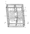
- Fig. 1 shows a first embodiment of a Schwingungstilgeran extract 1 with a base 2, which is designed as a frame and four extending approximately in the direction of gravity stator 3, four longitudinal bars 4, each connecting two stands 3 together, and four cross members 5, which also each two stands together connect, so that the base 2 with the uprights 3, the longitudinal bars 4 and the crossbars 5 forms a cuboid.
- the vibration damper assembly 1 further comprises an absorber mass 6, which may be composed of a plurality of individual mass elements 7, for example.
- an absorber mass 6, which may be composed of a plurality of individual mass elements 7, for example.
- the use of mass elements has the advantage that they can be transported individually and spent in place and assembled there.
- the absorber mass 6 has a center of mass, not shown, which is located for example in the middle of the absorber mass 6 in the direction of gravity.
- the base 2 two curved rails 8 are attached.
- the two rails 8 are parallel to each other and have the same curvature. Its concave side is directed upwards in the direction of gravity.
- the rails 8 are fixed to the uprights 3 of the base 2. However, this attachment is solvable.
- the rails 8 can be fixed to the stand in the direction of gravity in different positions, such as a comparison of Fig. 1 to 3 shows. However, the ends of the rails 8 are always positioned at the same height in the direction of gravity.
- the rails 8 can be fixed at discrete positions on the uprights 3. Each position is defined by a hole 9 in a stand 3. But it is also possible to attach the rails 8 in other ways to the uprights 3, so that virtually a stepless positioning in the direction of gravity is possible.
- the absorber mass 6 is surrounded by a frame-like carriage 10.
- the frame may look like this from a comparison of Fig. 1 to 3 shows, are moved in the direction of gravity along the absorber mass 6 and fixed to the absorber mass 6 at different positions.
- load-bearing rollers 11 are rotatably mounted on the carriage 10 load-bearing rollers 11 are rotatably mounted.
- the load-bearing rollers 11 may also be referred to as "heavy duty rollers".
- the absorber mass 6 can certainly have a mass of several tons.
- the load-bearing rollers 11 must be able to accommodate this load.
- the carriage 10 also has at least one guide roller 12 which guides the carriage 10 transversely to the direction of gravity on a rail 8.
- a corresponding guide roller 12 or even a pair of guide rollers 12 is provided for each rail 8.
- the absorber mass 6 has for attachment of the carriage 10 a plurality of bores 13, which are arranged one above the other in the direction of gravity.
- the carriage 10 can be connected by means of only schematically illustrated pins 14 with the absorber mass 6 by a respective pin 14 is inserted into a corresponding bore 13.
- the absorber mass 6 executes a movement which corresponds to a pendulum motion.
- the natural frequency of such a pendulum depends inter alia on the length of the pendulum
- the natural frequency can be reduced by using, as in Fig. 2 represented, the rails and the carriage 10 in the direction of gravity further up the base 2, more precisely mounted on the uprights 3, the center of mass of the absorber mass 6 but unchanged leaves.
- the pendulum length is shortened, so that increases the natural frequency.
- a rail 8 can of course also use another arrangement in which a concave curved track is provided for the load-bearing rollers 8, for example a plate or the like.
- the in Fig. 1 to 3 shown construction of the vibration damper assembly 1 can be kept relatively narrow in the direction of vibration, ie in the direction of movement of the absorber mass 6.
- the absorber mass 6 is in turn supported by load-bearing rollers 11 on the rails 8. It is relatively flat, so it requires only a small height.
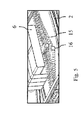
- each return element 15 has a fastening device 16. Furthermore, each return element 15 is arranged between two transverse members 5 of the base 2. Each return element 15 may already have a certain bias.
- the fastening device 16 is arranged at a position in which a force balance prevails without external forces. If the return element 15 is formed for example from two identical springs, then the fastener 16 is located in the center of the base 2 in the direction of movement of the absorber mass 6 between the springs.
- each of the restoring elements 15 can now individually with the absorber mass 6 couple or decouple from this. If the return element is connected to the absorber mass 6, then it counteracts a movement of the absorber mass 6, because the springs of the return element 15 are compressed in one direction and stretched in the other direction.
- the return element 15 can be connected with its fastening means 16 also with the base. In this case, it is also set, so can not perform uncontrolled movements. At the same time, however, it no longer acts on the absorber mass 6.
- These return elements are integrated and preloaded in the base. The additional activation takes place via a connection of the respective restoring element by attaching the fastening device 16 to the absorber mass 6. This has the advantage that for tuning the natural frequency of the vibration on the tower of the wind turbine no parts must be removed or added, the frequency tuning therefore with simple Means can be accomplished.
- a rail 8 with an infinitely large radius of curvature can also be used, that is to say a flat rail 8.
- Fig. 5 For example, four return elements 15 are activated and a return element 15 is deactivated.
- Fig. 6 shows a way to integrate into the load-bearing rollers 11 still a damping function.
- a guide roller 12 it is also possible with a guide roller 12 to integrate a damping function.
- the load-bearing roller 11 is rotatably mounted on a shaft journal 17 of the carriage 10.
- An axle box, which will usually be present, is not shown for reasons of clarity.
- a copper plate 18 On the load-bearing roller 11, a copper plate 18 is fixed, which rotates upon rotation of the load-bearing roller 11 with.
- the copper disc 18 moves relative to the permanent magnets 20, 21.
- the permanent magnets 20, 21 generate a magnetic field that passes through the copper plate 18 approximately perpendicular. But this is not absolutely necessary.
- electrical currents are induced in the copper disk 18. Since the copper disc 18 has an ohmic resistance, the eddy currents generate heat, which is dissipated as power loss to the environment. This power loss is removed from the oscillatory motion, which is thereby damped.
- the load-bearing roller 11 can also be driven by a motor.
- the motor is preferably connected to a controller, which in turn is connected to a sensor, such as a vibration sensor.
- the controller is thus able to respond to measured vibrations of the tower and to drive the motor so that the absorber mass 6 is moved so that the vibrations are damped.
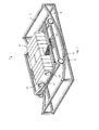
- Fig. 7 shows a further embodiment of a Schwingungstilgeran extract, in the same and functionally identical elements with the same reference numerals as in Fig. 1 to 6 be designated.
- the absorber mass 6 is not supported in this case directly on load-bearing rollers 11 on the rails 8.
- the absorber mass 6 is rather supported via an additional wheel-rail arrangement on the rails 8.
- the additional wheel-rail arrangement has additional rails 22, which extend approximately at right angles to the rails 8.
- the absorber mass 6 is supported by additional rollers 23 on the additional rails 22.
- the additional rails 22 are supported on the carriage 10. This will do that in the Fig. 1 to 5 shown system, each having a degree of freedom, extended to a system with two degrees of freedom.
- different vibration modes can be adjusted by choosing different radii of curvature of the rails 8 and the additional rails 22 and / or by forces of the restoring devices 15, if desired. Again, it is possible to make a change in the center of gravity of the absorber mass 6 to the additional rails 22 and thus also to the rails 8 in the direction of gravity.
Landscapes
- Engineering & Computer Science (AREA)
- General Engineering & Computer Science (AREA)
- Mechanical Engineering (AREA)
- Sustainable Energy (AREA)
- Architecture (AREA)
- Combustion & Propulsion (AREA)
- Chemical & Material Sciences (AREA)
- Life Sciences & Earth Sciences (AREA)
- Sustainable Development (AREA)
- Emergency Management (AREA)
- Environmental & Geological Engineering (AREA)
- Business, Economics & Management (AREA)
- Structural Engineering (AREA)
- Civil Engineering (AREA)
- Vibration Prevention Devices (AREA)
Priority Applications (2)
| Application Number | Priority Date | Filing Date | Title |
|---|---|---|---|
| DK12008532.9T DK2746483T3 (da) | 2012-12-21 | 2012-12-21 | Anordning til dæmpning af svingninger. |
| EP12008532.9A EP2746483B1 (fr) | 2012-12-21 | 2012-12-21 | Dispositif d'amortisseur d'oscillations |
Applications Claiming Priority (1)
| Application Number | Priority Date | Filing Date | Title |
|---|---|---|---|
| EP12008532.9A EP2746483B1 (fr) | 2012-12-21 | 2012-12-21 | Dispositif d'amortisseur d'oscillations |
Publications (2)
| Publication Number | Publication Date |
|---|---|
| EP2746483A1 true EP2746483A1 (fr) | 2014-06-25 |
| EP2746483B1 EP2746483B1 (fr) | 2015-11-18 |
Family
ID=47602742
Family Applications (1)
| Application Number | Title | Priority Date | Filing Date |
|---|---|---|---|
| EP12008532.9A Active EP2746483B1 (fr) | 2012-12-21 | 2012-12-21 | Dispositif d'amortisseur d'oscillations |
Country Status (2)
| Country | Link |
|---|---|
| EP (1) | EP2746483B1 (fr) |
| DK (1) | DK2746483T3 (fr) |
Cited By (20)
| Publication number | Priority date | Publication date | Assignee | Title |
|---|---|---|---|---|
| WO2017036581A1 (fr) | 2015-08-28 | 2017-03-09 | Fm Energie Gmbh & Co.Kg | Amortisseur de vibrations présentant une masse rotative |
| WO2017121633A1 (fr) * | 2016-01-15 | 2017-07-20 | Fm Energie Gmbh & Co.Kg | Amortisseur d'oscillations à frein électromagnetique pour éoliennes |
| CN107630959A (zh) * | 2017-11-21 | 2018-01-26 | 成都大运汽车集团有限公司 | 一种弹簧与滚轮结合的减震装置 |
| CN107701650A (zh) * | 2017-11-21 | 2018-02-16 | 成都大运汽车集团有限公司 | 一种简易带警报功能的避震装置 |
| EP3415786A1 (fr) * | 2017-06-13 | 2018-12-19 | GE Renewable Technologies Wind B.V. | Amortisseurs de masse accordés pour amortir un mouvement d'oscillation d'une structure |
| WO2019154557A1 (fr) | 2018-02-08 | 2019-08-15 | Esm Energie- Und Schwingungstechnik Mitsch Gmbh | Amortisseur de vibrations de torsion à entraînement à courroie |
| WO2019185196A1 (fr) | 2018-03-30 | 2019-10-03 | Esm Energie- Und Schwingungstechnik Mitsch Gmbh | Ressort magnetique linéaire et utilisation dans des amortisseurs de vibrations |
| CN110616819A (zh) * | 2019-09-23 | 2019-12-27 | 广州大学 | 一种新型发电式电磁阻尼调谐质量阻尼器 |
| CN110805529A (zh) * | 2019-09-20 | 2020-02-18 | 株洲时代新材料科技股份有限公司 | 调谐质量阻尼装置 |
| CN110805530A (zh) * | 2019-09-20 | 2020-02-18 | 株洲时代新材料科技股份有限公司 | 调谐质量阻尼装置 |
| DE102018218999A1 (de) * | 2018-11-07 | 2020-05-07 | Maurer Engineering Gmbh | Massedämpfer zur Dämpfung von Schwingungen eines Bauwerks, Bauwerk mit einem solchen Massedämpfer und Verfahren zur Einstellung der natürlichen Frequenz eines Massedämpfers |
| WO2020239248A1 (fr) * | 2019-05-29 | 2020-12-03 | Esm Energie- Und Schwingungstechnik Mitsch Gmbh | Amortisseur d'impulsion pour constructions et installations minces et hautes |
| US10934997B2 (en) | 2016-10-28 | 2021-03-02 | Siemens Gamesa Renewable Energy A/S | Damping wind turbine tower oscillations |
| WO2021237979A1 (fr) * | 2020-05-28 | 2021-12-02 | 北京金风科创风电设备有限公司 | Dispositif intégré d'amortissement, amortisseur, et ensemble générateur éolien |
| CN113775902A (zh) * | 2020-06-10 | 2021-12-10 | 北京金风科创风电设备有限公司 | 阻尼器支撑装置、阻尼系统、塔筒及塔筒的组装方法 |
| EP4290096A1 (fr) * | 2022-06-09 | 2023-12-13 | Wölfel Engineering GmbH & Co. KG. | Dispositif amortisseur de vibrations |
| DE102022207585A1 (de) | 2022-07-25 | 2024-01-25 | Maurer Engineering Gmbh | Bauwerksschwingungsdämpfer |
| CN119123000A (zh) * | 2024-10-29 | 2024-12-13 | 上海大学 | 一种轨道非线性能量汇装置及胞元化组件 |
| US12241519B2 (en) | 2019-09-20 | 2025-03-04 | Zhuzhou Times New Material Technology Co., Ltd | Tuned mass damping device |
| WO2026052602A1 (fr) | 2024-09-04 | 2026-03-12 | Esm Energie- Und Schwingungstechnik Mitsch Gmbh | Ensemble amortisseur à masse accordée pour structures hautes et minces |
Families Citing this family (2)
| Publication number | Priority date | Publication date | Assignee | Title |
|---|---|---|---|---|
| WO2022207146A1 (fr) * | 2021-03-31 | 2022-10-06 | Fm Energie Gmbh & Co.Kg | Amortisseur rotatif à courants de foucault adaptatif en température |
| EP4403792A1 (fr) | 2023-01-17 | 2024-07-24 | Wölfel Engineering GmbH & Co. KG. | Agencement d'amortisseur de vibrations, en particulier pour constructions très minces, et procédé de montage d'un agencement d'amortisseur de vibrations |
Citations (8)
| Publication number | Priority date | Publication date | Assignee | Title |
|---|---|---|---|---|
| JPH08200438A (ja) | 1995-01-19 | 1996-08-06 | Ishikawajima Harima Heavy Ind Co Ltd | 揺れ止め装置 |
| JPH10227331A (ja) * | 1997-02-14 | 1998-08-25 | Fujita Corp | 制振装置 |
| JP2841487B2 (ja) | 1989-06-28 | 1998-12-24 | 石川島播磨重工業株式会社 | 構造物制振装置 |
| JPH1151111A (ja) * | 1997-08-04 | 1999-02-23 | Takenaka Komuten Co Ltd | 制振装置 |
| JP2000002017A (ja) * | 1998-06-16 | 2000-01-07 | Kajima Corp | 付加マス型制震装置の制御装置及びそれを含む制震制御装置並びに制震構造物 |
| JP2008190645A (ja) * | 2007-02-06 | 2008-08-21 | Shimizu Corp | 振動低減機構およびその諸元設定方法 |
| JP2008249122A (ja) * | 2007-03-30 | 2008-10-16 | Kitakyushu Foundation For The Advancement Of Industry Science & Technology | 制振装置 |
| WO2009068599A2 (fr) | 2007-11-28 | 2009-06-04 | Vestas Wind Systems A/S | Procédé pour amortir des oscillations dans une éolienne |
-
2012
- 2012-12-21 DK DK12008532.9T patent/DK2746483T3/da active
- 2012-12-21 EP EP12008532.9A patent/EP2746483B1/fr active Active
Patent Citations (8)
| Publication number | Priority date | Publication date | Assignee | Title |
|---|---|---|---|---|
| JP2841487B2 (ja) | 1989-06-28 | 1998-12-24 | 石川島播磨重工業株式会社 | 構造物制振装置 |
| JPH08200438A (ja) | 1995-01-19 | 1996-08-06 | Ishikawajima Harima Heavy Ind Co Ltd | 揺れ止め装置 |
| JPH10227331A (ja) * | 1997-02-14 | 1998-08-25 | Fujita Corp | 制振装置 |
| JPH1151111A (ja) * | 1997-08-04 | 1999-02-23 | Takenaka Komuten Co Ltd | 制振装置 |
| JP2000002017A (ja) * | 1998-06-16 | 2000-01-07 | Kajima Corp | 付加マス型制震装置の制御装置及びそれを含む制震制御装置並びに制震構造物 |
| JP2008190645A (ja) * | 2007-02-06 | 2008-08-21 | Shimizu Corp | 振動低減機構およびその諸元設定方法 |
| JP2008249122A (ja) * | 2007-03-30 | 2008-10-16 | Kitakyushu Foundation For The Advancement Of Industry Science & Technology | 制振装置 |
| WO2009068599A2 (fr) | 2007-11-28 | 2009-06-04 | Vestas Wind Systems A/S | Procédé pour amortir des oscillations dans une éolienne |
Cited By (37)
| Publication number | Priority date | Publication date | Assignee | Title |
|---|---|---|---|---|
| JP2018529901A (ja) * | 2015-08-28 | 2018-10-11 | エフエム・エネルギー・ゲーエムベーハー・ウント・コンパニー・カーゲー | 回転質量を有する振動吸収器 |
| WO2017036581A1 (fr) | 2015-08-28 | 2017-03-09 | Fm Energie Gmbh & Co.Kg | Amortisseur de vibrations présentant une masse rotative |
| US10711859B2 (en) | 2015-08-28 | 2020-07-14 | Fm Energie Gmbh & Co. Kg | Vibration absorber having a rotating mass |
| EP3341627B1 (fr) * | 2015-08-28 | 2019-09-25 | FM Energie GmbH & Co. KG | Amortisseur de vibrations présentant une masse rotative |
| CN108350969A (zh) * | 2015-08-28 | 2018-07-31 | Fm能源有限责任两合公司 | 带有旋转的质量的振动缓冲器 |
| US10718232B2 (en) | 2016-01-15 | 2020-07-21 | Fm Energie Gmbh & Co. Kg | Vibration absorber having an electromagnetic brake for wind turbines |
| WO2017121633A1 (fr) * | 2016-01-15 | 2017-07-20 | Fm Energie Gmbh & Co.Kg | Amortisseur d'oscillations à frein électromagnetique pour éoliennes |
| US10934997B2 (en) | 2016-10-28 | 2021-03-02 | Siemens Gamesa Renewable Energy A/S | Damping wind turbine tower oscillations |
| US10774893B2 (en) | 2017-06-13 | 2020-09-15 | General Electric Renovables Espana, S.L. | Tuned mass dampers for damping an oscillating movement of a structure |
| EP3415786A1 (fr) * | 2017-06-13 | 2018-12-19 | GE Renewable Technologies Wind B.V. | Amortisseurs de masse accordés pour amortir un mouvement d'oscillation d'une structure |
| CN107701650A (zh) * | 2017-11-21 | 2018-02-16 | 成都大运汽车集团有限公司 | 一种简易带警报功能的避震装置 |
| CN107630959A (zh) * | 2017-11-21 | 2018-01-26 | 成都大运汽车集团有限公司 | 一种弹簧与滚轮结合的减震装置 |
| WO2019154557A1 (fr) | 2018-02-08 | 2019-08-15 | Esm Energie- Und Schwingungstechnik Mitsch Gmbh | Amortisseur de vibrations de torsion à entraînement à courroie |
| CN111954771B (zh) * | 2018-02-08 | 2022-06-10 | Esm能源及振动控制技术米奇有限公司 | 具有带驱动器的旋转减振器 |
| US11255409B2 (en) | 2018-02-08 | 2022-02-22 | Esm Energie-Und Schwingungstechnik Mitsch Gmbh | Rotating vibration absorber comprising a belt drive |
| CN111954771A (zh) * | 2018-02-08 | 2020-11-17 | Esm能源及振动控制技术米奇有限公司 | 具有带驱动器的旋转减振器 |
| WO2019185196A1 (fr) | 2018-03-30 | 2019-10-03 | Esm Energie- Und Schwingungstechnik Mitsch Gmbh | Ressort magnetique linéaire et utilisation dans des amortisseurs de vibrations |
| DE102018218999A1 (de) * | 2018-11-07 | 2020-05-07 | Maurer Engineering Gmbh | Massedämpfer zur Dämpfung von Schwingungen eines Bauwerks, Bauwerk mit einem solchen Massedämpfer und Verfahren zur Einstellung der natürlichen Frequenz eines Massedämpfers |
| WO2020239248A1 (fr) * | 2019-05-29 | 2020-12-03 | Esm Energie- Und Schwingungstechnik Mitsch Gmbh | Amortisseur d'impulsion pour constructions et installations minces et hautes |
| US11781336B2 (en) | 2019-05-29 | 2023-10-10 | Esm Energie—Und Schwingungstechnik Mitsch Gmbh | Impulse damper for tall, narrow structures and installations |
| CN110805530B (zh) * | 2019-09-20 | 2020-12-01 | 株洲时代新材料科技股份有限公司 | 调谐质量阻尼装置 |
| CN110805529A (zh) * | 2019-09-20 | 2020-02-18 | 株洲时代新材料科技股份有限公司 | 调谐质量阻尼装置 |
| US12241519B2 (en) | 2019-09-20 | 2025-03-04 | Zhuzhou Times New Material Technology Co., Ltd | Tuned mass damping device |
| CN110805529B (zh) * | 2019-09-20 | 2020-12-01 | 株洲时代新材料科技股份有限公司 | 调谐质量阻尼装置 |
| CN110805530A (zh) * | 2019-09-20 | 2020-02-18 | 株洲时代新材料科技股份有限公司 | 调谐质量阻尼装置 |
| CN110616819B (zh) * | 2019-09-23 | 2024-05-28 | 广州大学 | 一种新型发电式电磁阻尼调谐质量阻尼器 |
| CN110616819A (zh) * | 2019-09-23 | 2019-12-27 | 广州大学 | 一种新型发电式电磁阻尼调谐质量阻尼器 |
| US11746749B2 (en) | 2020-05-28 | 2023-09-05 | Beijing Goldwind Science & Creation Windpower Equipment Co., Ltd. | Damping integrated device, damper and wind turbine |
| WO2021237979A1 (fr) * | 2020-05-28 | 2021-12-02 | 北京金风科创风电设备有限公司 | Dispositif intégré d'amortissement, amortisseur, et ensemble générateur éolien |
| CN113775902B (zh) * | 2020-06-10 | 2023-08-22 | 北京金风科创风电设备有限公司 | 阻尼器支撑装置、阻尼系统、塔筒及塔筒的组装方法 |
| CN113775902A (zh) * | 2020-06-10 | 2021-12-10 | 北京金风科创风电设备有限公司 | 阻尼器支撑装置、阻尼系统、塔筒及塔筒的组装方法 |
| EP4290096A1 (fr) * | 2022-06-09 | 2023-12-13 | Wölfel Engineering GmbH & Co. KG. | Dispositif amortisseur de vibrations |
| WO2023237536A1 (fr) | 2022-06-09 | 2023-12-14 | Wölfel Engineering Gmbh + Co. Kg | Ensemble amortisseur d'oscillations |
| DE102022207585A1 (de) | 2022-07-25 | 2024-01-25 | Maurer Engineering Gmbh | Bauwerksschwingungsdämpfer |
| WO2024022698A1 (fr) | 2022-07-25 | 2024-02-01 | Maurer Engineering Gmbh | Amortisseur de vibrations structural |
| WO2026052602A1 (fr) | 2024-09-04 | 2026-03-12 | Esm Energie- Und Schwingungstechnik Mitsch Gmbh | Ensemble amortisseur à masse accordée pour structures hautes et minces |
| CN119123000A (zh) * | 2024-10-29 | 2024-12-13 | 上海大学 | 一种轨道非线性能量汇装置及胞元化组件 |
Also Published As
| Publication number | Publication date |
|---|---|
| DK2746483T3 (da) | 2016-01-11 |
| EP2746483B1 (fr) | 2015-11-18 |
Similar Documents
| Publication | Publication Date | Title |
|---|---|---|
| EP2746483B1 (fr) | Dispositif d'amortisseur d'oscillations | |
| EP3665398B1 (fr) | Amortisseur de vibrations equipé d'un dispositif d'amortisseement en rotation | |
| EP3170232B1 (fr) | Infrastructure destinée à augmenter la résistance d'un composant à haute tension vis-à-vis des tremblements de terre | |
| EP2885587B1 (fr) | Construction porteuse pour modules solaire | |
| EP2522850B1 (fr) | Réducteur de vibrations pour tour et tour dotée d'un réducteur de vibrations pour tour | |
| EP3610172A1 (fr) | Amortissement des vibrations d'une tour de centrale éolienne | |
| EP3804121A1 (fr) | Installation solaire ayant un table de modules pivotantes et fixables | |
| DE102019111314B4 (de) | Verbindungsvorrichtung für lautsprecherboxen und anordnung von untereinander hängenden lautsprecherboxen | |
| WO2020126070A1 (fr) | Amortisseur de vibrations d'impulsions pour structures élancées élevées | |
| DE202017105133U1 (de) | Schwenkbare Halte-, Stütz- und/oder Verstelleinrichtung für Solarmodule | |
| DE102022204900B3 (de) | Federnd gelagertes Getriebegehäuse II | |
| EP3698067B1 (fr) | Amortisseur de vibration, en particulier pour une armoire de distribution | |
| EP3825495B1 (fr) | Système d'ossature porteuse et noeuds de raccordement permettant de fixer des modules fonctionnels à une ossature porteuse du système d'ossature porteuse | |
| EP2730709B1 (fr) | Agencement de réduction de vibrations | |
| EP0334241A1 (fr) | Installation de conversion d'énergie éolienne | |
| WO2017162565A1 (fr) | Dispositif pivotant de retenue, de support et/ou de déplacement pour modules solaires | |
| EP2730799B1 (fr) | Agencement de réduction de vibrations pour la réduction des vibrations | |
| EP3575630B1 (fr) | Système d'amortissement de vibrations | |
| EP4290096B1 (fr) | Dispositif amortisseur de vibrations | |
| WO2017005365A1 (fr) | Grue à tour | |
| EP4103329B1 (fr) | Bielle de réaction destinée à intercepter un couple d'entraînement et ensemble rouleaux muni d'une bielle de réaction | |
| DE102022207585A1 (de) | Bauwerksschwingungsdämpfer | |
| EP2999930B1 (fr) | Dispositif de suivi solaire pour modules solaire munis de pseudo-articulations élastiques ou à ressort | |
| EP3922879A1 (fr) | Amortisseur pendulaire | |
| EP2702975A1 (fr) | Disposition d'entraînement pour l'entraînement de perturbation |
Legal Events
| Date | Code | Title | Description |
|---|---|---|---|
| PUAI | Public reference made under article 153(3) epc to a published international application that has entered the european phase |
Free format text: ORIGINAL CODE: 0009012 |
|
| 17P | Request for examination filed |
Effective date: 20121221 |
|
| AK | Designated contracting states |
Kind code of ref document: A1 Designated state(s): AL AT BE BG CH CY CZ DE DK EE ES FI FR GB GR HR HU IE IS IT LI LT LU LV MC MK MT NL NO PL PT RO RS SE SI SK SM TR |
|
| AX | Request for extension of the european patent |
Extension state: BA ME |
|
| R17P | Request for examination filed (corrected) |
Effective date: 20141127 |
|
| RBV | Designated contracting states (corrected) |
Designated state(s): AL AT BE BG CH CY CZ DE DK EE ES FI FR GB GR HR HU IE IS IT LI LT LU LV MC MK MT NL NO PL PT RO RS SE SI SK SM TR |
|
| RIC1 | Information provided on ipc code assigned before grant |
Ipc: E04B 1/98 20060101AFI20150408BHEP Ipc: F16F 7/104 20060101ALI20150408BHEP Ipc: E04H 9/02 20060101ALI20150408BHEP Ipc: F03D 11/00 20060101ALI20150408BHEP |
|
| GRAP | Despatch of communication of intention to grant a patent |
Free format text: ORIGINAL CODE: EPIDOSNIGR1 |
|
| INTG | Intention to grant announced |
Effective date: 20150604 |
|
| GRAS | Grant fee paid |
Free format text: ORIGINAL CODE: EPIDOSNIGR3 |
|
| GRAA | (expected) grant |
Free format text: ORIGINAL CODE: 0009210 |
|
| AK | Designated contracting states |
Kind code of ref document: B1 Designated state(s): AL AT BE BG CH CY CZ DE DK EE ES FI FR GB GR HR HU IE IS IT LI LT LU LV MC MK MT NL NO PL PT RO RS SE SI SK SM TR |
|
| REG | Reference to a national code |
Ref country code: GB Ref legal event code: FG4D Free format text: NOT ENGLISH |
|
| REG | Reference to a national code |
Ref country code: CH Ref legal event code: EP |
|
| REG | Reference to a national code |
Ref country code: AT Ref legal event code: REF Ref document number: 761658 Country of ref document: AT Kind code of ref document: T Effective date: 20151215 |
|
| REG | Reference to a national code |
Ref country code: IE Ref legal event code: FG4D Free format text: LANGUAGE OF EP DOCUMENT: GERMAN |
|
| REG | Reference to a national code |
Ref country code: FR Ref legal event code: PLFP Year of fee payment: 4 |
|
| REG | Reference to a national code |
Ref country code: DE Ref legal event code: R096 Ref document number: 502012005216 Country of ref document: DE |
|
| REG | Reference to a national code |
Ref country code: DK Ref legal event code: T3 Effective date: 20160108 |
|
| REG | Reference to a national code |
Ref country code: NL Ref legal event code: MP Effective date: 20160218 |
|
| REG | Reference to a national code |
Ref country code: LT Ref legal event code: MG4D |
|
| PG25 | Lapsed in a contracting state [announced via postgrant information from national office to epo] |
Ref country code: NL Free format text: LAPSE BECAUSE OF FAILURE TO SUBMIT A TRANSLATION OF THE DESCRIPTION OR TO PAY THE FEE WITHIN THE PRESCRIBED TIME-LIMIT Effective date: 20151118 Ref country code: HR Free format text: LAPSE BECAUSE OF FAILURE TO SUBMIT A TRANSLATION OF THE DESCRIPTION OR TO PAY THE FEE WITHIN THE PRESCRIBED TIME-LIMIT Effective date: 20151118 Ref country code: IT Free format text: LAPSE BECAUSE OF FAILURE TO SUBMIT A TRANSLATION OF THE DESCRIPTION OR TO PAY THE FEE WITHIN THE PRESCRIBED TIME-LIMIT Effective date: 20151118 Ref country code: IS Free format text: LAPSE BECAUSE OF FAILURE TO SUBMIT A TRANSLATION OF THE DESCRIPTION OR TO PAY THE FEE WITHIN THE PRESCRIBED TIME-LIMIT Effective date: 20160318 Ref country code: ES Free format text: LAPSE BECAUSE OF FAILURE TO SUBMIT A TRANSLATION OF THE DESCRIPTION OR TO PAY THE FEE WITHIN THE PRESCRIBED TIME-LIMIT Effective date: 20151118 Ref country code: LT Free format text: LAPSE BECAUSE OF FAILURE TO SUBMIT A TRANSLATION OF THE DESCRIPTION OR TO PAY THE FEE WITHIN THE PRESCRIBED TIME-LIMIT Effective date: 20151118 Ref country code: NO Free format text: LAPSE BECAUSE OF FAILURE TO SUBMIT A TRANSLATION OF THE DESCRIPTION OR TO PAY THE FEE WITHIN THE PRESCRIBED TIME-LIMIT Effective date: 20160218 |
|
| PG25 | Lapsed in a contracting state [announced via postgrant information from national office to epo] |
Ref country code: RS Free format text: LAPSE BECAUSE OF FAILURE TO SUBMIT A TRANSLATION OF THE DESCRIPTION OR TO PAY THE FEE WITHIN THE PRESCRIBED TIME-LIMIT Effective date: 20151118 Ref country code: SE Free format text: LAPSE BECAUSE OF FAILURE TO SUBMIT A TRANSLATION OF THE DESCRIPTION OR TO PAY THE FEE WITHIN THE PRESCRIBED TIME-LIMIT Effective date: 20151118 Ref country code: LV Free format text: LAPSE BECAUSE OF FAILURE TO SUBMIT A TRANSLATION OF THE DESCRIPTION OR TO PAY THE FEE WITHIN THE PRESCRIBED TIME-LIMIT Effective date: 20151118 Ref country code: PL Free format text: LAPSE BECAUSE OF FAILURE TO SUBMIT A TRANSLATION OF THE DESCRIPTION OR TO PAY THE FEE WITHIN THE PRESCRIBED TIME-LIMIT Effective date: 20151118 Ref country code: GR Free format text: LAPSE BECAUSE OF FAILURE TO SUBMIT A TRANSLATION OF THE DESCRIPTION OR TO PAY THE FEE WITHIN THE PRESCRIBED TIME-LIMIT Effective date: 20160219 Ref country code: FI Free format text: LAPSE BECAUSE OF FAILURE TO SUBMIT A TRANSLATION OF THE DESCRIPTION OR TO PAY THE FEE WITHIN THE PRESCRIBED TIME-LIMIT Effective date: 20151118 Ref country code: BE Free format text: LAPSE BECAUSE OF NON-PAYMENT OF DUE FEES Effective date: 20151231 Ref country code: PT Free format text: LAPSE BECAUSE OF FAILURE TO SUBMIT A TRANSLATION OF THE DESCRIPTION OR TO PAY THE FEE WITHIN THE PRESCRIBED TIME-LIMIT Effective date: 20160318 |
|
| PG25 | Lapsed in a contracting state [announced via postgrant information from national office to epo] |
Ref country code: CZ Free format text: LAPSE BECAUSE OF FAILURE TO SUBMIT A TRANSLATION OF THE DESCRIPTION OR TO PAY THE FEE WITHIN THE PRESCRIBED TIME-LIMIT Effective date: 20151118 |
|
| REG | Reference to a national code |
Ref country code: CH Ref legal event code: PL |
|
| REG | Reference to a national code |
Ref country code: DE Ref legal event code: R097 Ref document number: 502012005216 Country of ref document: DE |
|
| PG25 | Lapsed in a contracting state [announced via postgrant information from national office to epo] |
Ref country code: SM Free format text: LAPSE BECAUSE OF FAILURE TO SUBMIT A TRANSLATION OF THE DESCRIPTION OR TO PAY THE FEE WITHIN THE PRESCRIBED TIME-LIMIT Effective date: 20151118 Ref country code: SK Free format text: LAPSE BECAUSE OF FAILURE TO SUBMIT A TRANSLATION OF THE DESCRIPTION OR TO PAY THE FEE WITHIN THE PRESCRIBED TIME-LIMIT Effective date: 20151118 Ref country code: EE Free format text: LAPSE BECAUSE OF FAILURE TO SUBMIT A TRANSLATION OF THE DESCRIPTION OR TO PAY THE FEE WITHIN THE PRESCRIBED TIME-LIMIT Effective date: 20151118 Ref country code: RO Free format text: LAPSE BECAUSE OF FAILURE TO SUBMIT A TRANSLATION OF THE DESCRIPTION OR TO PAY THE FEE WITHIN THE PRESCRIBED TIME-LIMIT Effective date: 20151118 |
|
| REG | Reference to a national code |
Ref country code: IE Ref legal event code: MM4A |
|
| PLBE | No opposition filed within time limit |
Free format text: ORIGINAL CODE: 0009261 |
|
| STAA | Information on the status of an ep patent application or granted ep patent |
Free format text: STATUS: NO OPPOSITION FILED WITHIN TIME LIMIT |
|
| PG25 | Lapsed in a contracting state [announced via postgrant information from national office to epo] |
Ref country code: MC Free format text: LAPSE BECAUSE OF FAILURE TO SUBMIT A TRANSLATION OF THE DESCRIPTION OR TO PAY THE FEE WITHIN THE PRESCRIBED TIME-LIMIT Effective date: 20151118 |
|
| 26N | No opposition filed |
Effective date: 20160819 |
|
| PG25 | Lapsed in a contracting state [announced via postgrant information from national office to epo] |
Ref country code: IE Free format text: LAPSE BECAUSE OF NON-PAYMENT OF DUE FEES Effective date: 20151221 Ref country code: CH Free format text: LAPSE BECAUSE OF NON-PAYMENT OF DUE FEES Effective date: 20151231 Ref country code: LI Free format text: LAPSE BECAUSE OF NON-PAYMENT OF DUE FEES Effective date: 20151231 |
|
| PG25 | Lapsed in a contracting state [announced via postgrant information from national office to epo] |
Ref country code: SI Free format text: LAPSE BECAUSE OF FAILURE TO SUBMIT A TRANSLATION OF THE DESCRIPTION OR TO PAY THE FEE WITHIN THE PRESCRIBED TIME-LIMIT Effective date: 20151118 |
|
| REG | Reference to a national code |
Ref country code: FR Ref legal event code: PLFP Year of fee payment: 5 |
|
| PG25 | Lapsed in a contracting state [announced via postgrant information from national office to epo] |
Ref country code: HU Free format text: LAPSE BECAUSE OF FAILURE TO SUBMIT A TRANSLATION OF THE DESCRIPTION OR TO PAY THE FEE WITHIN THE PRESCRIBED TIME-LIMIT; INVALID AB INITIO Effective date: 20121221 Ref country code: BG Free format text: LAPSE BECAUSE OF FAILURE TO SUBMIT A TRANSLATION OF THE DESCRIPTION OR TO PAY THE FEE WITHIN THE PRESCRIBED TIME-LIMIT Effective date: 20151118 |
|
| PG25 | Lapsed in a contracting state [announced via postgrant information from national office to epo] |
Ref country code: CY Free format text: LAPSE BECAUSE OF FAILURE TO SUBMIT A TRANSLATION OF THE DESCRIPTION OR TO PAY THE FEE WITHIN THE PRESCRIBED TIME-LIMIT Effective date: 20151118 |
|
| PG25 | Lapsed in a contracting state [announced via postgrant information from national office to epo] |
Ref country code: MT Free format text: LAPSE BECAUSE OF FAILURE TO SUBMIT A TRANSLATION OF THE DESCRIPTION OR TO PAY THE FEE WITHIN THE PRESCRIBED TIME-LIMIT Effective date: 20151118 |
|
| PG25 | Lapsed in a contracting state [announced via postgrant information from national office to epo] |
Ref country code: LU Free format text: LAPSE BECAUSE OF NON-PAYMENT OF DUE FEES Effective date: 20151221 |
|
| REG | Reference to a national code |
Ref country code: FR Ref legal event code: PLFP Year of fee payment: 6 |
|
| PG25 | Lapsed in a contracting state [announced via postgrant information from national office to epo] |
Ref country code: MK Free format text: LAPSE BECAUSE OF FAILURE TO SUBMIT A TRANSLATION OF THE DESCRIPTION OR TO PAY THE FEE WITHIN THE PRESCRIBED TIME-LIMIT Effective date: 20151118 |
|
| PG25 | Lapsed in a contracting state [announced via postgrant information from national office to epo] |
Ref country code: AL Free format text: LAPSE BECAUSE OF FAILURE TO SUBMIT A TRANSLATION OF THE DESCRIPTION OR TO PAY THE FEE WITHIN THE PRESCRIBED TIME-LIMIT Effective date: 20151118 Ref country code: TR Free format text: LAPSE BECAUSE OF FAILURE TO SUBMIT A TRANSLATION OF THE DESCRIPTION OR TO PAY THE FEE WITHIN THE PRESCRIBED TIME-LIMIT Effective date: 20151118 |
|
| REG | Reference to a national code |
Ref country code: AT Ref legal event code: MM01 Ref document number: 761658 Country of ref document: AT Kind code of ref document: T Effective date: 20171221 |
|
| PG25 | Lapsed in a contracting state [announced via postgrant information from national office to epo] |
Ref country code: AT Free format text: LAPSE BECAUSE OF NON-PAYMENT OF DUE FEES Effective date: 20171221 |
|
| P01 | Opt-out of the competence of the unified patent court (upc) registered |
Effective date: 20230524 |
|
| REG | Reference to a national code |
Ref country code: DE Ref legal event code: R082 Ref document number: 502012005216 Country of ref document: DE Representative=s name: KEIL & SCHAAFHAUSEN PATENTANWAELTE PARTGMBB, DE |
|
| PGFP | Annual fee paid to national office [announced via postgrant information from national office to epo] |
Ref country code: GB Payment date: 20251218 Year of fee payment: 14 |
|
| PGFP | Annual fee paid to national office [announced via postgrant information from national office to epo] |
Ref country code: DK Payment date: 20251217 Year of fee payment: 14 |
|
| PGFP | Annual fee paid to national office [announced via postgrant information from national office to epo] |
Ref country code: FR Payment date: 20251218 Year of fee payment: 14 |
|
| PGFP | Annual fee paid to national office [announced via postgrant information from national office to epo] |
Ref country code: DE Payment date: 20251218 Year of fee payment: 14 |