EP3632056B1 - Intitialisation d'un bus local - Google Patents
Intitialisation d'un bus local Download PDFInfo
- Publication number
- EP3632056B1 EP3632056B1 EP18726115.1A EP18726115A EP3632056B1 EP 3632056 B1 EP3632056 B1 EP 3632056B1 EP 18726115 A EP18726115 A EP 18726115A EP 3632056 B1 EP3632056 B1 EP 3632056B1
- Authority
- EP
- European Patent Office
- Prior art keywords
- data
- bus
- data bus
- counter value
- communication
- Prior art date
- Legal status (The legal status is an assumption and is not a legal conclusion. Google has not performed a legal analysis and makes no representation as to the accuracy of the status listed.)
- Active
Links
Images


Classifications
-
- H—ELECTRICITY
- H04—ELECTRIC COMMUNICATION TECHNIQUE
- H04L—TRANSMISSION OF DIGITAL INFORMATION, e.g. TELEGRAPHIC COMMUNICATION
- H04L12/00—Data switching networks
- H04L12/28—Data switching networks characterised by path configuration, e.g. LAN [Local Area Networks] or WAN [Wide Area Networks]
- H04L12/42—Loop networks
- H04L12/423—Loop networks with centralised control, e.g. polling
-
- H—ELECTRICITY
- H04—ELECTRIC COMMUNICATION TECHNIQUE
- H04L—TRANSMISSION OF DIGITAL INFORMATION, e.g. TELEGRAPHIC COMMUNICATION
- H04L12/00—Data switching networks
- H04L12/28—Data switching networks characterised by path configuration, e.g. LAN [Local Area Networks] or WAN [Wide Area Networks]
- H04L12/40—Bus networks
- H04L12/403—Bus networks with centralised control, e.g. polling
-
- H—ELECTRICITY
- H04—ELECTRIC COMMUNICATION TECHNIQUE
- H04L—TRANSMISSION OF DIGITAL INFORMATION, e.g. TELEGRAPHIC COMMUNICATION
- H04L12/00—Data switching networks
- H04L12/28—Data switching networks characterised by path configuration, e.g. LAN [Local Area Networks] or WAN [Wide Area Networks]
- H04L12/40—Bus networks
- H04L12/40006—Architecture of a communication node
- H04L12/40019—Details regarding a bus master
-
- H—ELECTRICITY
- H04—ELECTRIC COMMUNICATION TECHNIQUE
- H04L—TRANSMISSION OF DIGITAL INFORMATION, e.g. TELEGRAPHIC COMMUNICATION
- H04L12/00—Data switching networks
- H04L12/28—Data switching networks characterised by path configuration, e.g. LAN [Local Area Networks] or WAN [Wide Area Networks]
- H04L12/40—Bus networks
- H04L2012/4026—Bus for use in automation systems
Definitions
- the invention generally relates to the initialization of a local bus, in particular the information query in a local bus by means of relative addressing.
- Automation systems are used in particular to control industrial systems, buildings and means of transport.
- sensors and actuators are usually required to control an automation system. These monitor and control the process carried out by the system.
- the different sensors and actuators of an automation system are often also referred to as automation devices.
- These automation devices can either be connected directly to a controller of the automation system, or can initially be connected to input and output modules, which are often also referred to as I / O modules. These can then in turn be connected directly to the controller.
- the automation devices can either be integrated directly into the I / O modules or can be connected to them via cables or wirelessly.
- An automation system is usually controlled with the help of one or more programmable logic controllers, PLCs.
- the PLCs can be arranged hierarchically or decentrally in an automation system.
- the PLCs have different performance classes so that they can take on different controls and regulations depending on the computing and storage capacity.
- a PLC has inputs, outputs, a Operating system (firmware) and an interface via which a user program can be loaded.
- the user program defines how the outputs are to be switched depending on the inputs.
- the inputs and outputs can be connected to the automation devices and / or the I / O modules and the process carried out by the automation system can be monitored or controlled using the logic stored in the user program.
- the process is monitored by the sensors and the process is controlled by the actuators.
- the controller can also be referred to as a central controller or central unit and takes over the control of at least one automation device or I / O module connected to the controller.
- the direct connection of the automation devices with the at least one controller or the I / O modules with the at least one controller is in the form of parallel wiring, i.e. a line is laid from each automation device or each I / O module to the higher-level controller, very expensive.
- parallel wiring i.e. a line is laid from each automation device or each I / O module to the higher-level controller.
- bus systems are mostly used in automation technology today, with which the automation devices or the I / O modules can be connected to the controller.
- individual groups of automation devices or I / O modules are often first connected to one another using a specialized local bus to form a local bus system and then at least one Participants of this local bus are connected to the bus system that is connected to the controller.
- the local bus system can differ from the bus system that is used to establish the connection with the controller.
- the participant of a group of local bus participants connected to the bus system of the control is often also referred to as the local bus master.
- this local bus master can contain additional logics, circuits or functionalities that are necessary for connection to the bus system of the controller.
- the local bus master itself can also contain a PLC. This participant can also have logic and circuits for implementation between the two bus systems.
- the local bus master can therefore also be designed as a gateway or bus converter and ensures that the data present in the format of one bus system are converted into the format of the local bus system and vice versa. In most cases, but not necessarily, the local bus master specializes in connecting the local bus to the higher-level bus.
- the local buses used are mostly tailored to the specific application requirements of the automation devices or I / O modules or take their special hardware design into account.
- the groups of automation devices or I / O modules of the local bus system mostly form a subgroup of the automation system for performing a special task in the process carried out by the automation system.
- the data exchanged on the buses for the process are also often referred to as local bus data or process data, because this data contains information for regulating or controlling the process carried out by the automation system. These data can include, among other things, measurement data, control data, status data and / or other information. Depending on the bus protocol used, this data can be preceded by other data ( header) or appended ( tail). These other data can contain information relating to the data or information relating to internal communication on the local bus.
- the local bus users connected to a local bus can also be referred to as data bus users because they exchange data on the local bus.
- a data bus subscriber can serve to control or monitor a process, in particular by outputting control signals, for example to actuators, and / or by receiving measurement signals, for example from sensors.
- the data bus subscriber sets the control signals and / or measurement signals in process data for the local bus or vice versa.
- the data bus participants can also be referred to as local bus participants.
- a ring bus is a specialized form of the local bus, such as from U.S. 5,472,347 A known.
- the data bus subscribers for example the automation devices or I / O modules, are each connected to their directly adjacent data bus subscribers and data is passed on in sequence from one data bus subscriber to the other.
- the data transmitted on the local bus can also be referred to as local bus data.
- the data are therefore not sent to all data bus users at the same time, but one after the other, with a data bus user receiving data from its upstream data bus user and forwards data to its downstream data bus user.
- the data bus subscriber can process the received data between receiving the data and forwarding it.
- the ring bus thus has a down stream and an up stream of data.
- the data in a ring bus are usually transmitted in the form of data packets that pass through all data bus participants.
- data packets are provided with an address corresponding to the data bus subscriber, so that the data bus subscriber who has the corresponding address is informed that the data packet is directed to this data bus subscriber.
- the data bus subscribers in ring buses are often addressed according to their physical order in the ring bus, for example in DE 195 45 566 A1 described.
- this makes the self-administration of the ring bus very inflexible and static, especially when new data bus users are added to the ring bus or old ones are replaced.
- the object of the present invention is therefore to provide methods and devices with which flexible addressing is possible even when data bus users are exchanged or when the local bus is initialized, and with which information about the corresponding data bus users is also possible in a simple manner can be collected.
- the method according to the invention for communication with data bus users connected to a local bus, in particular a ring bus, with a local bus master comprises sending a first data packet from the local bus master to all data bus users in order to count communication-ready data bus users in a sequence, the first data packet having a first counter value, which is changed in the sequence by each of the communication-ready data bus participants.
- the first counter value can be a binary value, for example. In other words, the number of data bus users already ready for communication is determined with a first individual data packet. In this communication phase, the data bus participants do not need to be addressed.
- the first data packet for counting can for example be sent in a cycle frame on the local bus.
- a cycle frame can be defined, for example, as a recurring (cyclical), preferably equidistant, time interval in which data can be transmitted on the local bus.
- the cycle frame has, for example, at least one start identifier (SOC) and a time range for the transmission of data.
- SOC start identifier
- Several start identifiers (SOC) of successive cycle frames are advantageously at an equidistant time interval from one another.
- the specified time range is intended for the transmission of the data packets.
- the start identifier (SOC) and the data packets are transmitted via the local bus and pass through all data bus participants.
- the start identifier (SOC) is separate, that is to say can be transmitted as an independent symbol or is advantageously contained in a start data packet (SOC packet).
- one or more data packets are transmitted within the time range of the cycle frame.
- idle data are used in a cycle frame (Idle data) inserted, in particular adjacent to at least one data packet.
- the transmission of the data packets and / or the idle data advantageously brings about an uninterrupted signal on the local bus.
- the signal enables the data bus participants to synchronize themselves with it in terms of time.
- the cycle frame advantageously also has a trailer.
- the trailer has a variable length and follows the time range for data transmission, preferably up to the following start identifier (SOC) of the next cycle frame.
- SOC start identifier
- the trailer advantageously has idle data.
- Each data bus subscriber that is already ready for communication can change the first counter value contained in the data packet upon receipt of the individual data packet, for example increment or decrement it before the data packet or the part of the data packet containing the counter value is sent on to the next data bus subscriber.
- Data bus participants that are not yet ready for communication only pass the data packet through without changing the first counter value.
- a data bus subscriber can be ready for communication if it is clock-synchronized with the local bus and can receive data packets and forward them and is able to carry out processing with the data packets. If the local bus is a ring bus, the data packet is returned to the local bus master from the last data bus participant, regardless of whether it is already ready for communication or not.
- the ring bus can also be closed by a bridge unit that sends the data packets that are received in the downward direction back in the upward direction. This happens either again through all data bus participants so that they can carry out processing again, or past all data bus participants via a bypass connection.
- the local bus master uses the first counter value to know how many data bus users on the local bus are already ready for communication. To query information, the local bus master then generates a number of second data packets. The number of second data packets corresponds to the number of communication-ready data bus users indicated by the first counter value. If the first counter value has indicated, for example, that there are N data bus users ready for communication, then N second data packets are also generated and sent on the local bus, where N is a natural integer.
- the number of second data packets sent by the local bus master to the local bus is intended for a communication-ready data bus subscriber and is assigned to this on the basis of the respective relative position of the communication-ready data bus subscriber within the sequence.
- the communication-ready data bus users have changed the first counter value of the first data packet in a specific order.
- the number of second data packets are preferably sent on the local bus in an order that corresponds to the order in which the first counter value was changed. These second data packets can then be used to address the respective data bus subscribers without their address being known.
- the relative position of the communication-ready data bus subscribers in the local bus is determined and this relative position is then used to address the communication-ready data bus subscribers or to assign and send second data packets to them.
- the relative position of the data bus participants which does not depend on the physical position of the data bus participant but on its readiness for communication, flexible communication and information collection is possible.
- Each data packet of the number of second data packets is assigned to exactly one data bus subscriber who uses this second data packet to forward information to the local bus master.
- the local bus master accordingly addresses the data bus subscribers one after the other in this phase of communication, specifically in the order in which the data bus subscribers changed the first counter value of the first data packet.
- the data packets transmitted on the local bus described here can also be referred to as telegrams.
- the data packets can also be referred to as communication data packets, which are used in particular for programming and / or for controlling and / or for monitoring and / or for identifying at least one data bus participant.
- the data bus subscribers are used to control or monitor a process, in particular by outputting control signals, for example to actuators, and / or by receiving measurement signals, for example from sensors.
- the data bus participant sets the Control signals and / or measurement signals in data for the local bus or vice versa.
- the individual data packet used for the first count is of the same type as the number of second data packets that are generated by the local bus system and sent on the local bus according to the number of the first counter value.
- each data packet of the number of second data packets has a second counter value for assigning the data packet, the second counter value differing in each of the second data packets, ie having a different start value.
- This second counter value is used for the relative addressing of the data bus participants. If a data bus participant recognizes that a second counter value of a data packet used for relative addressing corresponds to a specific reference value, then this data bus participant recognizes that the data packet carrying this second counter value is intended for the data bus participant. In the case of relative addressing, each data bus participant changes the second counter value of each of the number of second data packets. The change can be an incrementing or decrementing of the second counter value.
- the local bus master can be adapted to adapt the second counter value in accordance with the number of data bus users counted, that is to say the first counter value, in such a way that every second counter value differs.
- every second counter value is adapted in such a way that the change in the second counter value by the data bus subscribers causes the second counter value to reach a reference value for only one communication-ready data bus subscriber.
- the reference value can, for example, be the same reference value in all data bus subscribers, so that the second counter value differs accordingly from each data packet. If the second counter value of a data packet reaches the reference value on a communication-ready data bus participant, then this data bus participant knows that the data packet is intended for this data bus participant.
- each data bus subscriber can be designed to carry out a comparison between the second counter value in each data packet from the number of second data packets and a reference value.
- the second Counter value can be represented by a binary representation.
- the data packet sent first of the number of second data packets can have a second counter value which corresponds to the highest binary representation of the possible value range for the second counter value. In other words, the data packet sent first from the number of second data packets has only ones in the second counter value.
- the range of values can depend on the maximum number of data bus participants that can be connected to the local bus.
- the first data bus subscriber increments the second counter value of the data packet sent first from the number of second data packets, then the latter experiences a zero crossing, ie the binary representation has only zeros.
- the reference value can also be a zero crossing of a number of significant last bits. If the reference value of the first data bus participant is zero, the first data bus participant recognizes in the example mentioned here that the data packet is directed to the first data bus participant, ie is assigned to it.
- the second data packet sent to the local bus from the number of second data packets can be intended for the second data bus subscriber, that is to say addressed to the latter. In this data packet, the local bus master can set the second counter value to a value that can be incremented by two data bus users before it crosses zero.
- the second data packet sent out of the number of second data packets can therefore be incremented by the first data bus subscriber and is incremented by the latter to the highest binary representation, ie to a value that has only ones.
- the first data bus participant knows that the data packet is not intended for the first data bus participant and sends it on on the local bus to the next communication-ready data bus participant. This once again increments the second counter value, which has already been incremented once.
- a zero crossing is experienced, so that the second communication-ready data bus subscriber knows that this data packet is intended for the second data bus subscriber.
- the local bus master can assign all data packets of the number of second data packets via the second counter value and its reaching of a reference value to the respective communication-ready data bus subscribers or address or direct them to the respective data bus subscribers. It is clear to the person skilled in the art that even if the incrementing is described here and a zero crossing is assumed as the reference value, this is also the case can be accomplished via a decrement and a one pass. In other words, the second counter value of the data packet sent first is set to zero. If this is decremented, the counter value jumps to only ones. The data packet sent second from the number of data packets then contains a one etc. as the start value for the second counter value correspond to.
- the counter value can preferably be set up to accept a reference value only exactly once, so that the data packets are assigned unambiguously. For example, a comparison with the reference value and then the incrementing / decrementing can also take place first.
- a data bus participant detects that a data packet is directed to the data bus participant because the second counter value in this data packet has reached a reference value that corresponds to a reference value stored in the data bus participant, the data bus participant can write information stored in the data bus participant into a field of the data packet, which is directed to the data bus participant. For example, the data bus participant can write its address in the field. In this way, the local bus master can collect information about the data bus participants.
- this includes comparing the first counter value and the second counter value of at least one data packet from the number of data packets on the local bus master after passing through the local bus, i.e. after the at least one data packet has been processed by each communication-ready data bus participant. If no further data bus subscribers have become ready for communication between the first counting and the return of the data packets to the local bus master, there is a defined relationship between the first counter value and the second counter value. For example, the second counter value of the first data packet from the number of second data packets is equal to the first counter value minus one and the second counter value of the last data packet from the number of second data packets is equal to the reference value, for example equal to zero.
- the second counter value of each data packet from the number of second data packets is then changed exactly once by each data bus subscriber in accordance with the number of data bus subscribers, that is to say the number indicated by the first counter value. If new data bus subscribers have become ready for communication during the first count with the aid of the first counter value and the sending of the number of second data packets, the local bus master cannot recognize a fixed relationship between the first and the second counter value. In this case, the local bus master again sends a single first data packet with a first counter value to the data bus subscribers, so in this case the local bus master again counts the data bus subscribers that are ready for communication.
- the new counter value can be compared with the old counter value. If these match, it can be determined that there was an error in the transmission, or that a data bus participant, although it has signaled readiness for communication, by processing the first data packet with the first counter value, but this is not able to count the number of second data packets to process. If the new first counter value deviates from the old counter value, at least one further data bus subscriber has become ready for communication. In this case, the local bus master sends the number of second data packets again, the number being adapted to the new first counter value and the second counter values of the number of second data packets also being adapted to the new first counter value. This process is repeated until the comparison shows that no further data bus subscribers have meanwhile become ready for communication.
- the local bus master sends out individual first data packets with a first counter value at certain time intervals in order to check the number of data bus users connected to the local bus.
- the local bus master after receiving the number of second data packets, the local bus master again sends a data packet with a first counter value to check whether no further data bus users have become ready for communication in the meantime. Ie the Local bus master verifies the data received in the number of second data packets.
- the above-mentioned object is also achieved by a local bus master of a local bus, in particular a ring bus, with data bus users.
- the local bus master has a means for sending a first data packet to all data bus users, the first data packet being used to count the communication-ready data bus users in a sequence.
- the first data packet can have a first counter value which is changed in the sequence by each communication-ready data bus subscriber. After receiving the first data packet, the local bus master can then use the first counter value of the data packet to determine how many data bus users are already ready for communication.
- the local bus master has a means for sending a number of second data packets, the number of which is based on the first counter value.
- Each of the second data packets is assigned to the communication-ready data bus subscribers in the sequence based on the respective relative position, it being possible for the assignment to take place on the basis of a second counter value.
- the means for transmitting can be a transmitter circuit or a transceiver circuit.
- the circuits can be implemented in an application-specific integrated circuit ( ASIC) or in a field-programmable (logic) gate arrangement ( FPGA).
- the above-mentioned object is also achieved by a method for communication with a local bus master of a local bus, in particular a ring bus, with communication-ready data bus users.
- the method includes receiving a first data packet from a local bus master at a communication-ready data bus subscriber, the first data packet having a first counter value, changing the first counter value in the data packet by the communication-ready data bus subscriber, receiving a number of second data packets, each of the second data packets having one has second counter value.
- the method includes writing information stored in the communication-ready data bus subscriber, for example an address, into a field of a data packet from the number of second data packets that is assigned to the communication-ready data bus subscriber.
- the data bus subscriber can recognize that it has received a data packet from the number of second Data packets is assigned when the data bus subscriber changes the second counter value of the data packet and this then reaches a reference value.
- the second counter value of the number of second data packets is different in each data packet, so that the reference value is only reached exactly once if all communication-ready data bus users change the second counter value of a data packet from the number of second data packets.
- the above-mentioned object is also achieved by a communication-ready data bus subscriber of a local bus, in particular a ring bus, with a local bus master.
- the communication-ready data bus subscriber has a means for receiving a first data packet from a local bus master, the first data packet having a first counter value, a means for changing the first counter value in the first data packet, a means for receiving a number of second data packets, and a means for writing information stored in the communication-ready data bus subscriber, for example an address, into a field of a data packet from the number of second data packets which is assigned to the communication-ready data bus subscriber.
- a local bus system consisting of a local bus master and at least one data bus participant.
- the local bus master has a means for sending a first data packet to all data bus users, the first data packet being used to count the communication-ready data bus users in a sequence.
- the first data packet can have a first counter value which is changed in the sequence by each communication-ready data bus subscriber.
- the local bus master can furthermore have a means for receiving the first data packet with the first counter value changed by each communication-ready data bus subscriber. After receiving the first data packet, the local bus master can then use the first counter value of the data packet to determine how many data bus users are already ready for communication.
- the local bus master has a means for sending a number of second data packets, the number of which is based on the first counter value. Each of the second data packets is assigned based on the respective relative position of the communication-ready data bus subscribers in the sequence, the assignment being made on the basis of the second counter value. The assignment can be accomplished by giving every second data packet a different start value for the second counter value.
- the communication-ready data bus subscriber has a means for receiving the individual first data packet from a local bus master, the first data packet having the first counter value, a means for changing the first counter value in the first data packet, a means for receiving the number of second data packets and a means for writing information stored in the communication-ready data bus subscriber, for example an address, into a field of a data packet from the number of second data packets which is assigned to the communication-ready data bus subscriber.
- the local bus master can have a means for receiving the second data packets changed by the communication-ready data bus subscribers and can read out the data written into the second data packets by the communication-ready data bus subscribers.
- the above object is also achieved by a computer readable medium containing code that causes a computer to carry out one of the methods described herein.
- the code can be stored in the local bus master and / or in the data bus participant.
- the code is stored in a firmware memory of the local bus master or in a memory accessible by the data bus subscribers.
- FIG. 1 shows a schematic block diagram of an automation system. It will be understood by a person skilled in the art that the automation system shown is only an example and all the elements, modules, components, participants and units belonging to the automation system can be configured differently but can still fulfill the basic functionalities described here.
- the automation system shown has a higher-level controller 1, which can be implemented, for example, with a programmable logic controller, PLC.
- PLC programmable logic controller
- Such a PLC 1 basically serves to control and regulate the process carried out by the automation system.
- PLCs 1 in automation systems also take on more extensive functions, such as visualization, alarming and recording of all data relating to the process, and as such the PLC 1 functions as a man-machine interface.
- There are PLCs 1 in different performance classes that have different resources (computing capacity, storage capacity, number and type of inputs and outputs, and interfaces) that enable the PLC 1 to control and regulate the process of the automation system.
- a PLC 1 mostly has a modular structure and consists of individual components, each of which fulfills a different task.
- a PLC 1 usually consists of a central computing module (with one or more main processors and memory modules) and several modules with inputs and outputs. Such modular PLC 1 can easily be expanded by adding assemblies. It depends on the complexity of the process and the complexity of the structure of the automation system which assemblies must be integrated in the PLC 1. In today's automation systems, the PLC 1 is mostly no longer an independent system, but the PLC 1 is connected to the Internet or intranet via appropriate interfaces - not shown here. This means that the PLC 1 is part of a network via which or from which the PLC 1 can receive information, instructions, programming, etc.
- the PLC 1 can receive information about the materials supplied to the process via a connection to a computer located on the intranet or the Internet, so that the process can be optimally controlled by knowing their number or nature, for example. It is also conceivable that the PLC 1 is controlled by a user through access from the intranet or Internet. For example, a user can access the PLC 1 with the aid of a computer, also called a master computer, and check, change or correct its user programming. Accordingly, access to the PLC 1 is possible from one or more remote control rooms or control centers.
- the master computers can optionally have visualization devices for displaying process sequences.
- the PLC 1 is connected to automation devices. In order to keep the wiring effort low, bus systems are used for these connections.
- the PLC 1 is connected to a local bus master 3 of a subordinate local bus system by means of a superordinate bus 2, which in the embodiment shown here can be a field bus.
- a local bus master 3 of a local bus be connected to the higher-level bus 2, as in the exemplary embodiment shown here, but also any other participants - not shown here - that are designed for communication with the PLC 1.
- the higher-level bus 2 is connected to the local bus master 3 in the exemplary embodiment shown here.
- the local bus master 3 has a first interface 4 which is designed in such a way that it can be connected to the higher-level bus 2.
- the interface 4 can have a receptacle in the form of a socket, for example, and the higher-level bus 2 can have a plug that can be received by the socket.
- the plug and the socket can be, for example, a modular plug and a modular socket, i.e. each wire of the higher-level bus 2 is electrically or optically connected to a connection in the modular socket.
- an interface 4 is also familiar with other possibilities of how an interface 4 is to be designed so that the local bus master 3 can be connected electrically or optically to the higher-level bus 2.
- Those skilled in the art are familiar with screw, twist, click or plug connections with the help of which an electrical or optical connection can be established. In most cases, a male connector is received by a female counterpart. This receptacle mostly not only establishes the electrical or optical connection, but also ensures that the two parts are mechanically coupled and can only be detached from one another again with the application of a certain force.
- the higher-level bus 2 is permanently wired to the interface 4.
- the local bus master 3 in the exemplary embodiment shown here has a further second interface in order to connect the local bus master 3 to the local bus.
- On data bus subscribers 7a, 7b, ..., 7n are connected to or form the local bus.
- the local bus is advantageously designed in such a way that a data packet sent by the local bus master 3 is transmitted back to the local bus master 3 by all of the data bus users 7a, 7b,..., 7n connected to the local bus.
- a data bus subscriber 7a, 7b, ..., 7n always receives only part of the data packet from its upstream data bus subscriber 7a, 7b, ..., 7n.
- the local bus is advantageously designed in an annular structure. Such local buses can also be referred to as ring bus 6.
- the local bus can alternatively also be in the form of a strand or a star or a combination or mixed form of the aforementioned.
- the data packets are sent and received via the second interface of the local bus master 3.
- the second interface is divided into a first part 5a and a second part 5b.
- the first part 5a of the second interface establishes the downward connection in the ring bus 6 and the second part 5b of the second interface establishes the upward connection in the ring bus 6.
- the ring bus 6, whose data transmission direction is indicated by arrows in the in Figure 1
- the exemplary embodiment shown has, in the exemplary embodiment shown here, the data bus subscribers 7a, 7b, ..., 7n.
- these data bus users 7a, 7b, ..., 7n each have an interface 8 in order to receive data from an upstream or preceding data bus user 7a, 7b, ..., 7n.
- this receives data from the upstream local bus master 3 via the interface 8.
- the data bus subscribers 7a, 7b to forward subsequent data bus subscribers 7a, 7b, ..., 7n.
- data bus subscriber 7a it sends data to the downstream data bus subscriber 7b via interface 9.
- Interfaces 8 and 9 serve to propagate data in the downward direction of ring bus 6, ie away from local bus master 3. Further
- the data bus subscribers 7a, 7b the data bus subscribers 7a, 7b,.
- interface 10 is designed to receive data from the downstream or subsequent data bus participant 7b and interface 11 is designed to forward data to the upstream or preceding data bus participant, here the local bus master 3. It can therefore also be said that interfaces 9 and 11 are transmitter interfaces, whereas interfaces 8 and 10 are receiver interfaces.
- connections between the interfaces and the PLC 1 or the data bus subscribers 7a, 7b, ..., 7n are implemented using cables or printed circuit boards and / or for direct or indirect contacting using electrical contacts.
- Another alternative is that the individual connections are established wirelessly, and the interfaces provide the necessary conversions to the radio standards used.
- the local bus master 3 is thus arranged in a decentralized manner from the data bus subscribers 7a, 7b, ..., 7n
- the data bus participants 7a, 7b, ..., 7n and the local bus master 3 - which also represents a data bus participant of the ring bus 6 - can also be connected directly to one another.
- contacts of one data bus subscriber can access corresponding receptacles or receptacle contacts of a directly adjacent data bus subscriber in order to establish an electrical connection between the data bus subscribers so that data can be sent in the downward and upward direction.
- the data bus subscribers 7a, 7b,..., 7n can have receptacles on the side facing away from the master and contacts on the side facing the master. If the data bus subscribers 7a, 7b, ..., 7n are then lined up accordingly, the contacts of one data bus subscriber 7a, 7b, ..., 7n each engage in the receptacles of the other data bus subscriber 7a, 7b, ..., 7n and an electrical connection can be created.
- the local bus master 3 then has corresponding contacts on the side that reach into the receptacles of the first data bus subscriber 7a so to generate an electrical connection between the interfaces 5a and 8 or the interfaces 5b and 11.
- the person skilled in the art is also familiar with other possibilities, such as pressure contacts, knife and fork contacts, as to how two data bus subscribers 7a, 7b,.
- the data bus subscribers 7a, 7b, ..., 7n and the local bus master 3 can also have mechanical receptacles or mechanical fastening means with which the individual data bus subscribers 7a, 7b, ..., 7n and the local bus master 3 can be connected to one another.
- a data bus subscriber 7a, 7b,..., 7n can have a projection on one side and an undercut on the other side. If the data bus subscribers 7a, 7b, ..., 7n are then lined up, a projection engages in an undercut of the other data bus subscribers 7a, 7b, ..., 7n, so that a mechanical coupling is created.
- the data bus subscribers 7a, 7b, ..., 7n can also be arranged on a common receptacle, for example a top hat rail.
- the data bus subscribers 7a, 7b, ..., 7n can have corresponding fastening means for fastening on the top-hat rail.
- the data bus subscribers 7a, 7b, ..., 7n can also have, for example, detachably connectable fastening means with which the data bus subscribers 7a, 7b, ..., 7n can be fastened either to the top-hat rail or to another receptacle.
- the detachably connectable fastening means can be exchangeable and a corresponding fastening means for the desired receptacle can be connected to the data bus subscribers 7a, 7b, ..., 7n so that they can be fastened to the desired receptacle.
- the data bus subscribers 7a, 7b, ..., 7n in the in Figure 1 also has a processing unit 12, which consists, for example, of a processing component and a logic unit.
- the processing unit 12 can also be referred to as the overall circuit of the data bus subscriber.
- the processing unit 12 receives data via the inputs 8 and 10 and outputs data to the outputs 9 and 11.
- the processing unit 12 can receive or output data from the inputs / and outputs 13 and 14.
- the processing unit 12 has access to a memory 12 'of the data bus subscriber 7a, 7b, ..., 7n in which, for example, data, process data, or instruction lists are stored.
- the processing unit 12 can be designed to process received data and output data.
- Data to be processed can be received either from an upstream data bus subscriber or from inputs 13 of the data bus subscriber 7a, 7b,..., 7n.
- the inputs 13 of the data bus subscriber 7a, 7b,..., 7n can be connected to sensors 15 which send measurement data, status data, etc., for example.
- Processed data can be output either to a downstream data bus subscriber or at outputs 14 of the data bus subscriber 7a, 7b, ..., 7n.
- the data bus subscribers 7a, 7b For the sake of simplicity, the data bus subscribers 7a, 7b,.
- the person skilled in the art is aware, however, that the data bus subscribers 7a, 7b,..., 7n can have a large number of inputs and outputs 13 and 14 and can be connected to a large number of different sensors 15 and actuators 16.
- the feature characterizing the sensors 15 is that the sensors 15 record data or signals and send them to the data bus subscribers 7a, 7b, ..., 7n, whereas actuators 16 data or signals from the data bus subscribers 7a, 7b, ..., 7n receive and take an action based on this data or signals.
- the interfaces 8, 9, 10 and 11 can be integrated in a module unit and the data bus subscribers 7a, 7b, ..., 7n can be plugged onto this module unit.
- the modular units can also be referred to as basic elements of the ring bus 6.
- the ring bus infrastructure is created by the modular units and the data bus subscribers 7a, 7b, ..., 7n are interchangeable, so that the ring bus 6 can be set up with any data bus subscribers 7a, 7b, ..., 7n.
- With the help of the module units it is also ensured that even if a data bus subscriber 7a, 7b, ..., 7n is removed, the communication between the remaining data bus subscribers 7a, 7b, ..., 7n is not interrupted because communication via the existing modular units happens.
- the data bus subscribers 7a, 7b Even if the data bus subscribers 7a, 7b,.
- the ring bus 6 shown in the exemplary embodiment shown here is based on cycle frame communication.
- Each data packet is sent from the local bus master 3 in the downward direction to the first data bus subscriber 7a of the ring bus 6. This receives a first part of the data packet via the interface 8. Such a part of the data packet is also referred to below as a piece or unit.
- the data bus subscriber 7a then processes the part and then forwards the part to the next data bus subscriber 7b via interface 9, preferably at the same time the first data bus subscriber 7a receives a second part of the data packet, etc.
- the size of the parts of the data packet i.e.
- the denomination of the data packet depends on the capacity of the data bus subscribers 7a, 7b, ..., 7n, for example a fixed number of bits, for example 8 bits of the data packet, can be present at the data bus subscriber 7a, 7b, ..., 7n for processing at the same time.
- the data packet accordingly passes through the data bus subscribers 7a, 7b, ..., 7n in units, pieces or parts, for example in parts or symbols of 8 bits.
- the part of the data packet which has been processed by the last data bus participant, in the exemplary embodiment shown here, data bus participant 7n then runs through the ring bus 6 in the upward direction, so that the parts are sent upwards again from the last data bus participant 7n in the direction of the local bus master 3 by all the data bus participants 7a, 7b, ..., 7n.
- the last data bus participant 7n either has a switchable bridge that connects the interface 9 to the interface 10 or a switchable bridge - not shown here - is connected to the last data bus participant 7n, which takes over the function of the parts of the data packet from the interface 9 to lead to the interface 10.
- the interface 10 of the data bus subscriber 7n can also be connected directly to the interface 5b of the local bus master 3 with the aid of a bypass line - not shown here.
- the units of the data packet or the data packets can be looped back to the local bus master 3 by the individual data bus subscribers 7a, 7b, ..., 7n, as in the exemplary embodiment shown here, without further processing taking place.
- the units of the data packet are processed again in the upward direction so that the data packet can be processed twice, once in the downward direction to the last data bus subscriber 7n and once in the upward direction to the local bus master 3 be done by signal refreshment and / or phase shift.
- the local bus 6 must be initialized. That is, the local bus master 3 must learn which data bus subscribers 7a, 7b, ..., 7n are available and can query information from them . If the local bus 6 is designed so that the data bus subscribers 7a, 7b, ..., 7n can also be changed during operation, which is referred to as hot swap, then the local bus master 3 must also be capable of the to recognize new data bus participants and to query this information.
- the local bus master 3 uses a first data packet and a number of second data packets for this initial initialization or for the intermediate initialization.
- the first data pallet is sent to the local bus 6 without being addressed and passes through all data bus participants 7a, 7b, ..., 7n.
- the number of second data packets is then sent on the local bus 6 and also passes through all data bus users 7a, 7b, ..., 7n.
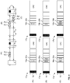
- the first data packet and the number of second data packets are of the same type. A corresponding one
- the data packet 17 shown as an example consists of a general header part - which can also be called a header -, an information part - which can also be called payload - and a checksum part - which can also be called a checksum.
- the header contains a field 18 which contains a unique bit pattern ENUM which occurs only once and which can also be referred to as a code word or identifier.
- the number and configuration of unique bit patterns or code words depend on the coding used on the local bus 6. Alternatively or additionally, however, special bit patterns or code words can also be defined in the bus protocol used. It is only important that the data bus subscribers 7a, 7b,. In the exemplary embodiment shown here, the data bus subscribers 7a, 7b, ..., 7n know that when a field 18 with a bit pattern ENUM is received, it is a data packet 17 for initialization or intermediate initialization.
- the header can also contain further information that can be used to control or check the data packet 17 and the data contained therein.
- the person skilled in the art is familiar with a large number of fields that can be contained in the header.
- the information part of the data packet 17 has several fields that can be used for initialization and intermediate initialization.
- the data packet 17 has a first counter value 23 and a second counter value 19.
- the first counter value 23 is used to count the data bus subscribers 7a, 7b,..., 7n on the local bus 6.
- the first counter value becomes 23 of each Data bus subscriber 7a, 7b, ..., 7n that is ready for communication, ie changed by each data bus subscriber 7a, 7b, ..., 7n that can process the data packet 17, for example.
- This change can consist in an incrementing or decrementing of the value of the first counter value 23.
- the data packet 17 also has a second counter value 19, which is used to assign the data packet 17 to the communication-ready data bus subscribers 7a, b,..., 7n, as follows with regard to the Figures 3 to 7 is explained in more detail.
- the data packet has a field 20 which can be used by the data bus users 7a, 7b,..., 7n in order to communicate their stored address to the local bus master 3.
- the data packet 17 also has a field 21 with which the local bus master 3 can assign a new address to the data bus users 7a, 7b, ..., 7n.
- the data packet 17 can also have a further field 22 which can carry control information for the respective data bus subscribers 7a, 7b,..., 7n.
- the data packet 17 is divided into symbols of 8 bits each.
- the data packet 17 is also received and processed in this denomination by the data bus subscribers 7a, 7b, ..., 7n. Ie first of all the local bus master 3 sends the symbol or field ENUM 18 to the first data bus participant 7a, after a predetermined time, the local bus master 3 sends another symbol of the header of the data packet 17 to the data bus participant 7a, which in turn sends the symbol or field at the same time ENUM 18 to the data bus subscriber 7b.
- Figure 3 shows an example of the initialization of the local bus 6.
- only data bus subscribers 7a and 7n are ready for communication.
- data bus subscriber 7b is present on local bus 6, it is not yet ready for communication, which is represented by the fact that data bus subscriber 7b only passes through the downward and upward data stream.
- the local bus master 3 sends a first data packet 17 symbol by symbol to the communication-ready data bus subscriber 7a. This is indicated by the first data packet 17 at position (A) of the local bus 6. That is to say, the data bus subscriber 7a first receives the field 18 of the first data packet 17 with the one-to-one bit pattern and is aware that an initialization is now taking place.
- the field 23 When the field 23 is then received at the data bus subscriber 7a, the latter can carry out processing with it, namely change the value of this field 23.
- the field 23 has a binary value and the data bus subscriber 7a increments the binary value.
- the value of the first counter value 23 was set to 0000 by the local bus master 3 and the data bus subscriber 7a has this value incremented by one to 0001 was sent by local bus master 3. In the exemplary embodiment shown here, this is shown below with the identification of the data packet as data packet 17 '.
- the data bus subscriber 7a itself also sends the data packet 17 'symbol-by-symbol to the next data bus subscriber 7b.
- the data bus subscriber 7b Since the data bus subscriber 7b is not yet ready for communication, it forwards the symbols of the data packet 17 'directly to the next data bus subscriber, in the exemplary embodiment shown here, to the data bus subscriber 7n. This is indicated by the data packet 17 ′ at position (B) of the local bus 6.
- the data packet 17 ' was therefore not processed by the data bus subscriber 7b that is not yet ready for communication, ie the value of the first counter value corresponds to the value to which the data bus subscriber 7a has incremented it, namely 0001.
- the data bus subscriber 7n then receives the data packet 17' and initially recognizes this Unique bit pattern 18.
- the first counter value 23 is incremented to 0010 because the data bus subscriber 7n is already ready for communication.
- the data bus subscriber 7n forwards the data packet 17 ′′ changed in this way back to the local bus master 3. This is indicated by the data packet 17 ′′ at position (C) of the local bus 6.
- the local bus master 3 can then read out the first counter value 23 from the data packet 17 ′′ and can thereby find out how many data bus users 7a, 7n that are ready for communication are present on the local bus 6. This is because only the data bus users 7a, 7n that are ready to communicate change the counter value 23, however, the data bus subscribers 7b that are not ready for communication do not change this.
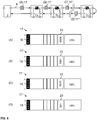
- the local bus master 3 then generates data packets 17 in the number of communication-ready data bus users 7a, 7n indicated by the first counter value 23; this is shown in FIG Figure 4 shown.
- the local bus master 3 generates two second data packets 17a and 17b corresponding to the first counter value 23.
- Each data packet 17a, 17b has a second counter value 19a, 19b. With the aid of this second counter value 19a, 19b, the two data packets 17a, 17b are assigned to the communication-ready data bus users 7a and 7n.
- the local bus master 3 sets the second counter value 19a of the data packet 17a to the highest binary representation that the second counter value 19a can assume, in the exemplary embodiment shown here to 1111 17a is set to a reduced value, here to 1110.
- the data packets 17a, 17b are then sent from the local bus master 3 to the first data bus subscriber 7a. This is indicated by the data packets 17a and 17b at position (A) of the local bus 6.
- the first data bus subscriber 7a receives the two data packets 17a and 17b symbol by symbol.
- the data bus subscriber 7a increments the second counter value 19a and 19b of the two data packets 17a and 17b.
- the data bus subscriber 7a determines that there is a zero crossing, i.e. the second counter value 19a, 19b of a data packet jumps to zero when incrementing, the data bus subscriber 7a recognizes that the corresponding data packet 17a, 17b in which the second counter value 19a, 19b jumps to zero is directed to the data bus subscriber 7a.
- the data packet 17a sent first is on the data bus subscriber 7a directed.
- the second counter value 19a experiences a zero crossing when the second counter value 19a is increased by the data bus subscriber 7a.
- the data bus subscriber 7a knows that the following symbols which pass through the data bus subscriber 7a are intended for this data bus subscriber 7a.
- the second counter value 19a precedes the other fields in the information part of the data packet 17a, so that when a zero crossing of the second counter value 19a is detected, the data bus subscriber 7a can process the following symbols.
- the data bus subscriber 7a is designed to write its address in the field 20a of the data packet 17a directed to the data bus subscriber 7a.
- the address of the data bus subscriber 7a is # 42.
- the person skilled in the art is aware that the data bus subscriber 7a can also be designed to write other information into the data packet 17a and that the address information is only used here as an example.
- the data bus subscriber 7a determines the end of the data packet 17a by receiving the symbol with the one-to-one bit pattern 18b of the second data packet 17b sent.
- the data bus subscriber 7a also increases the second counter value 19b of this data packet 17b.
- the value of the second counter value 19b was adjusted by the local bus master 3 in such a way that the value of the second counter value 19b of the data packet 17b was reduced by one compared to the value of the second counter value 19a of the data packet 17a, a zero crossing is not yet recognized, but the value of the second counter value 19b of data packet 17b is only set from 1110 to 1111.
- the data bus subscriber 7a forwards the data packets 17a 'and 17b' symbol by symbol to the next data bus subscriber 7b. However, since this is still not ready for communication, the data packets 17a ', 17b' are forwarded unchanged to the next data bus subscriber 7n. This is indicated by the data packets 17a 'and 17b' at position (B) of the local bus 6.
- the data bus subscriber 7n also receives the data packets 17a 'and 17b' symbol by symbol and this data bus subscriber 7n is also adapted to increase the value of the second counter value 19a, 19b. This has the result that the value of the second counter value 19a of the data packet 17a 'is set from 0000 to 0001 and the value of the second counter value 19b of the data packet 17b' experiences a zero crossing.
- the data bus participant 7n recognizes in this case that the data packet 17b 'is directed to the data bus participant 7n and knows that the The following symbols are directed to the data bus subscriber 7n.
- the data bus subscriber 7n inserts its address into the field 20b of the data packet 17b ', the address of the data bus subscriber 7n being # 88.
- the person skilled in the art is aware that information other than the address information can also be written into the data packet 17b '.
- the data bus subscriber 7n forwards the symbols of the data packets 17a "and 17n" to the local bus master 3. This is indicated by the data packets 17a ′′ and 17b ′′ at position (C) of the local bus 6.
- the local bus master 3 receives the data packets 17a "and 17b" with the fields 20a and 20b and thus gains knowledge that the data bus subscriber 7a has the address # 42 and the data bus subscriber 7n the address # 88. If the data bus users 7a, 7n are adapted to write other information in the data packets 17a, 17b, the local bus master 3 accordingly gains knowledge of this information.
- the local bus master 3 can verify that the initialization was successful when the value of the second counter value 19b of the last data packet 17b ′′ is equal to zero, provided that no further processing of the data packets takes place in the upward direction.
- Figures 5a and 5b show the same situation as Figure 4 , namely the routing of two data packets 17a and 17b through the local bus 6, whereby each communication-ready data bus subscriber 7a, 7b, ..., 7n with a detected zero crossing of the value of the second counter value 19a, 19b its address in the following field 20a, 20b of the respective data packets 17a, 17b writes.
- the data bus subscriber 7b has become ready for communication.
- the data bus subscriber 7b does not simply pass the data packets 17a 'and 17b' through, but processes them. From the local bus master 3 to the data bus subscriber 7a, the situation corresponds to Figure 4 . This is indicated by the data packets 17a and 17b at position (A) of the local bus 6.
- the data bus subscriber 7a receives the data packets 17a, 17b, increases the values of the respective second counter values 19a, 19b and recognizes in the data packet 17a a zero crossing of the value of the second counter value 19a of this data packet 17a and writes its address # 42 in the field 20a of the data packet 17a.
- the data bus subscriber 7a also increases the value of the second Counter value 19b of the data packet 17b by a value from 1110 to 1111 and forwards the data packets 17a ', 17b' to the next data bus subscriber 7b. This is indicated by the data packets 17a 'and 17b' at position (B) of the local bus 6.
- the data bus subscriber 7b is now ready for communication and carries out the same processing operations as the data bus subscribers 7a and 7n.
- the data bus subscriber 7b increases the value of the second counter values 19a, 19b of the respective data packets 17a ', 17b' accordingly and detects a zero crossing at the value of the second counter value 19b of the data packet 17b '.
- the data bus subscriber 7b writes its address # 56 in the field 20b of the data packet 17b '.
- the data packets 17a 'and 17b' are passed from the data bus subscriber 7b to the next data bus subscriber 7n. This is indicated by the data packets 17a ′′ and 17b ′′ at position (C) of the local bus 6.
- the data bus subscriber 7n does not recognize a zero crossing in any of the data packets 17a ", 17b” because the data packet 17b "directed to this data bus subscriber 7n has already been used by the second data bus subscriber 7b to communicate its address.
- the data bus subscriber 7n increases accordingly the value of the second counter values 19a, 19b of the respective data packets 17a ", 17b” but does not communicate its address.
- the data bus subscriber 7n forwards the data packets 17a ′′′, 17b to the local bus master 3. This is done with the data packets 17a and 17b ′′′ Position (D) of the local bus 6.
- the local bus master 3 recognizes that the value of the second counter value 19b of the last data packet 17b ′′′ deviates from zero Data bus subscribers 7a, 7b, ..., 7n match.
- the local bus master 3 recognizes the difference between the value of the two iten counter value 19b of the last data packet 17b ′′′ compared to the value of the first counter value 23 used to count the communication-ready data bus subscribers 7a, 7b, ..., 7n, how many communication-ready data bus subscribers 7a, 7b, ..., 7n have been added.
- the local bus master 3 can use this information to send a corresponding number of data packets again. However, after recognizing that one or more new data bus subscribers 7b have become ready for communication, the local bus master 3 can wait for a predetermined time before another single first data packet 17 is used to count the data bus subscribers 7a, 7b, ... that are now ready for communication on the local bus 6. , 7n is sent, this is in Figure 6 shown.
- Figure 6 shows the renewed counting of the communication-ready data bus subscribers 7a, 7b, ..., 7n present on the local bus 6.
- the local bus master 3 sends a single first data packet 17 symbol by symbol to the communication-ready data bus subscriber 7a. This is indicated by the data packet 17 at position (A) of the local bus 6.
- the data bus subscriber 7a first receives the field 18 of the data packet with the one-to-one bit pattern and is aware that an initialization is now taking place.
- the field 23 is then received at the data bus subscriber 7a, the latter can carry out processing with it, namely change the value of this field 23.
- the field 23 has a binary value and the data bus subscriber 7a increments the binary value.
- the value of the first counter value 23 was set to 0000 by the local bus master 3 and the data bus subscriber 7a has this value incremented by one to 0001 Local bus master 3 was sent, this is shown in the embodiment shown here in the further with the identification of the data packet as data packet 17 '.
- the data bus subscriber 7a itself also sends the data packet 17 'symbol-by-symbol to the next data bus subscriber 7b.
- the data bus subscriber 7b receives the data packet 17 'and increments the value of the first counter value 23. That is, after passing through the data bus subscriber 7b, the data packet differs from the data packet 17' that was sent by the data bus subscriber 7a.
- this is shown further with the identification of the data packet as data packet 17 ′′.
- the data bus subscriber 7b itself also sends the data packet 17 ′′ on to the next data bus subscriber 7n symbol by symbol.
- the data bus subscriber 7n receives the data packet 17 ′′ and increments the value of the first counter value 23. That is, after passing through the data bus subscriber 7n, the data packet differs from the data packet 17 ′′ that was sent by the data bus subscriber 7b. In the exemplary embodiment shown here, this is shown below with the identification of the data packet as data packet 17 '.
- the data bus subscriber 7n itself also sends the data packet 17 ′′′ symbol by symbol to the local bus master 3.
- the local bus master 3 then knows how many communication-ready data bus subscribers 7a, 7b, ..., 7n the local bus 6 has.
- a number of second data packets 17a, 17b, 17c are then generated again by the local bus master 3.
- the values of the second counter values 19a, 19b, 19c of the respective data packets 17a, 17b, 17c are each adapted to assign the data packets 17a, 17b, 17c to the respective data bus users 7a, 7b, ..., 7n in sequence. It's in the Figures 7a and 7b shown.
- the local bus master 3 adjusts the value of the second counter value 19a, 19b, 19c of the respective data packets 17a, 17b, 17c so that they differ by one value and the first data packet 17a has the highest value of the second counter value 19a.
- the data packets 17a, 17b, 17c are sent symbol by symbol on the local bus 6. This is indicated by the data packets 17a, 17b, 17c at position (A) of the local bus 6.
- the data bus subscriber 7a receives the data packets 17a, 17b, 17c and increases the value of the second counter value 19a, 19b, 19c of the respective data packets 17a, 17b, 17c.
- the data bus subscriber 7a detects a zero crossing when the second counter value 19a is increased and detects that this data packet 17a is directed to the data bus subscriber 7a.
- the data bus subscriber 7a accordingly writes its address # 42 in the following field 20a of the data packet 17a.
- the data packets 17a ', 17b', 17c ' are forwarded from the data bus user 7a to the data bus user 7b. This is indicated by the data packets 17a ', 17b', 17c 'at position (B) of the local bus 6.
- This data bus subscriber 7b also increases the values of the second counter values 19a, 19b, 19c of the respective data packets 17a ', 17b', 17c 'and determines a zero crossing of the value of the second counter value 19b in the data packet 17b'.
- the data bus subscriber 7b recognizes that the data packet 17b 'is directed to the data bus subscriber 7b.
- the data bus subscriber 7b accordingly writes its address # 56 in the following field 20b of the data packet 17b '.
- the data packets 17a ′′, 17b ′′, 17c ′′ are forwarded from the data bus subscriber 7b to the data bus subscriber 7n.
- This data bus subscriber 7n also increases the values of the second counter values 19a, 19b, 19c of the respective data packets 17a ", 17b", 17c "and determines a zero crossing of the value of the second counter value 19c in the data packet 17c".
- the data bus subscriber 7n recognizes that the data packet 17c ′′ is sent to the data bus subscriber 7n is directed.
- the data bus subscriber 7n writes its address # 88 accordingly in the following field 20c of the data packet 17c ".
- the data packets 17a ′′′, 17b ′′′, 17c ′′′ are returned from the data bus subscriber 7n to the local bus master 3. This is done with the data packets 17a ′′′, 17b ′′′ , 17c ′′′ at position (D) of the local bus 6 indicated.
- the local bus master 3 After receiving the data packets 17a ′′′, 17b ′′′, 17c ′′′, the local bus master 3 knows the addresses of the data bus users 7a, 7b, ..., 7n, namely # 42, # 56, # 88. The local bus master 3 can also verify whether new data bus subscribers have meanwhile become ready for communication, for example by determining whether the value of the second counter value 19c of the last data packet 17c ′′′ is equal to zero or deviates. In the event that the value of the second counter value 19c of the last data packet 17c corresponds to zero, the address information in the data packets is valid. Otherwise it is counted again and the process begins again.
- the local bus master 3 can be adapted to send at least one first data packet 17 again to again to count all data bus participants 17a, 17b, 17c and to verify that the number of communication-ready data bus participants 7a, 7b, ..., 7n has not changed.
- the person skilled in the art is aware that other data can also be exchanged with the local bus master 3 in the manner shown.
- the person skilled in the art is also aware that the described methods can be used by the local bus master 3 during an initialization of the local bus 6 in order to collect information about the communication-ready data bus users 7a, 7b, ..., 7n even if the addresses of these data bus users 7a, 7b, ..., 7n are not known but the second counter value 19 can be used for the relative addressing of the data packets.
Landscapes
- Engineering & Computer Science (AREA)
- Computer Networks & Wireless Communication (AREA)
- Signal Processing (AREA)
- Small-Scale Networks (AREA)
Claims (15)
- Un procédé de communication avec des participants de bus de données (7a, 7b, ..., 7n) reliés à un bus local (6), en particulier à un bus en anneau, comprenant un maître de bus local (3), le procédé comprenant :l'envoi d'un premier paquet de données (17) par le maître de bus local (3) à tous les participants de bus de données (7a, 7b, ..., 7n) pour compter des participants de bus de données prêts à communiquer (7a, 7b, ..., 7n) en une séquence, le premier paquet de données (17) comportant une première valeur de compteur (23) qui est modifiée par chacun des participants de bus de données prêts à communiquer (7a, 7b, ..., 7n) dans la séquence ;l'envoi d'un nombre de seconds paquets de données (17a, 17b, 17c) par le maître de bus local (3) à tous les participants de bus de données (7a, 7b, ..., 7n), le nombre de seconds paquets de données (17a, 17b, 17c) étant basé sur la première valeur de compteur (23), et chacun des seconds paquets de données (17a, 17b, 17c) étant affecté à un des participants de bus de données prêts à communiquer (7a, 7b, ..., 7n) sur la base de la position relative respective des participants de bus de données prêts à communiquer (7a, 7b, ..., 7n) à l'intérieur de la séquence, et le premier paquet de données (17) et le nombre de seconds paquets de données (17a, 17b, 17c) étant du même type.
- Le procédé selon la revendication 1, dans lequel chacun des seconds paquets de données (17a, 17b, 17c) comporte une seconde valeur de compteur (19) pour l'affectation, la seconde valeur de compteur (19) étant modifiée par chacun des participants de bus de données prêts à communiquer (7a, 7b, ..., 7n) dans la séquence ; et
des valeurs de départ de la seconde valeur de compteur (19) se différencient en particulier pour chacun des seconds paquets de données (17a, 17b, 17c). - Le procédé selon une des revendications précédentes, comprenant en outre :
le traitement de chaque second paquet de données (17a, 17b, 17c) par l'intermédiaire de chacun des participants de bus de données prêts à communiquer (7a, 7b, ..., 7n), les seconds paquets de données (17a, 17b, 17c) étant traités les uns après les autres. - Le procédé selon la revendication 3, dans lequel le traitement comprend en outre :
la modification de la seconde valeur de compteur (19) dans chacun des seconds paquets de données (17a, 17b, 17c) par l'intermédiaire de chacun des participants de bus de données prêts à communiquer (7a, 7b, ..., 7n). - Le procédé selon la revendication 4, comprenant en outre :
la comparaison de la seconde valeur de compteur (19) dans chacun des seconds paquets de données (17a, 17b, 17c) avec une valeur de référence par l'intermédiaire de chacun des participants de bus de données prêts à communiquer (7a, 7b, ..., 7n). - Le procédé selon la revendication 5, comprenant en outre :
l'écriture d'une information mémorisée dans un participant de bus de données (7a, 7b, ..., 7n) dans un champ (20) d'un des seconds paquets de données (17a, 17b, 17c) lorsqu'une seconde valeur de compteur courante (19) du second paquet de données courant (17a, 17b, 17c) correspond à la valeur de référence. - Le procédé selon une des revendications précédentes, dans lequel la première valeur de compteur (23) et/ou la seconde valeur de compteur (19) sont une valeur binaire.
- Le procédé selon une des revendications précédentes, comprenant en outre :
la comparaison de la première valeur de compteur (23) et/ou de la seconde valeur de compteur (19) d'au moins un des seconds paquets de données (17a, 17b, 17c) avec une valeur attendue, après que le au moins un des seconds paquets de données (17a, 17b, 17c) a été traité par l'intermédiaire de chacun des participants de bus de données prêts à communiquer (7a, 7b, ..., 7n). - Le procédé selon la revendication 8, dans lequel la valeur attendue est basée sur la première valeur de compteur (23) du premier paquet de données (17) après que le premier paquet de données (17) a été traité par l'intermédiaire de chacun des participants de bus de données prêts à communiquer (7a, 7b, ..., 7n).
- Le procédé selon une des revendications 8 ou 9, comprenant en outre :
l'envoi à nouveau d'un premier paquet de données (17) vers tous les participants de bus de données (7a, 7b, ..., 7n) lorsque la comparaison révèle un écart. - Le procédé selon la revendication 10, comprenant en outre :
l'envoi à nouveau d'un nombre de seconds paquets de données (17a, 17b, 17c), le nombre étant basé sur la première valeur de compteur (23) du premier paquet de données à nouveau émis (17) après que le premier paquet de données à nouveau émis (17) a été traité par l'intermédiaire de chacun des participants de bus de données prêts à communiquer (7a, 7b, ..., 7n). - Un maître de bus local (3) d'un bus local (6), en particulier d'un bus en anneau, comprenant des participants de bus de données (7a, 7b, ..., 7n), le maître de bus local (3) comprenant :un moyen pour envoyer un premier paquet de données (17) à tous les participants de bus de données (7a, 7b, ..., 7n) pour compter des participants de bus de données prêts à communiquer (7a, 7b, ..., 7n) dans une séquence, le premier paquet de données (17) comportant une première valeur de compteur (23), pour une modification de cette première valeur de compteur (23) par l'intermédiaire de chaque participant de bus de données prêts à communiquer (7a, 7b, ..., 7n) dans la séquence ;un moyen pour recevoir le premier paquet de données (17) avec la première valeur de compteur (23) modifiée par l'intermédiaire de chaque participant de bus de données prêts à communiquer (7a, 7b, ..., 7n) ; etun moyen pour envoyer un nombre de seconds paquets de données (17a, 17b, 17c), le nombre étant basé sur la première valeur de compteur (23) du premier paquet de données reçu (17), et chacun des seconds paquets de données (17a, 17b, 17c) étant affecté à un des participants de bus de données prêts à communiquer (7a, 7b, ..., 7n) sur la base de la position relative des participants de bus de données prêts à communiquer (7a, 7b, ..., 7n) dans la séquence, et le premier paquet de données (17) et le nombre de seconds paquets de données (17a, 17b, 17c) étant du même type.
- Un système de bus local comprenant :
un bus local (6), en particulier un bus en anneau, comprenant un maître de bus local (3) selon la revendication 12, et comprenant des participants de bus de données (7a, 7b, ..., 7n). - Un procédé de communication comprenant un maître de bus local (3) d'un bus local (6), en particulier d'un bus en anneau, comprenant des participants de bus de données prêts à communiquer (7a, 7b, ..., 7n), le procédé comprenant :la réception, au niveau d'un participant de bus de données prêts à communiquer (7a, 7b, ..., 7n), d'un premier paquet de données (17) provenant d'un maître de bus local (3) selon la revendication 12, le premier paquet de données (17) comportant une première valeur de compteur (23) ;la modification de la première valeur de compteur (23) dans le premier paquet de données (17) par l'intermédiaire du participant de bus de données prêts à communiquer (7a, 7b, ..., 7n) ;la réception d'un nombre de seconds paquets de données (17a, 17b, 17c) ; etl'écriture d'une information mémorisée dans le participant de bus de données prêts à communiquer (7a, 7b, ..., 7n) dans un champ (20) d'un des seconds paquets de données (17a, 17b, 17c) lorsque le second paquet de données (17a, 17b, 17c) est affecté au participant de bus de données prêts à communiquer (7a, 7b, ..., 7n), et le premier paquet de données (17) et le nombre de seconds paquets de données (17a, 17b, 17c) étant du même type.
- Un participant de bus de données prêts à communiquer (7a, 7b, ..., 7n) d'un bus local (6), en particulier d'un bus en anneau, comprenant un maître de bus local (3), le participant de bus de données prêts à communiquer (7a, 7b, ..., 7n) comprenant :un moyen pour recevoir le premier paquet de données (17) issu du maître de bus local (3) selon la revendication 12, le premier paquet de données (17) comportant une première valeur de compteur (23) ;un moyen pour modifier la première valeur de compteur (23) dans le premier paquet de données (17) ;un moyen pour recevoir un nombre de seconds paquets de données (17a, 17b, 17c) ; etun moyen pour écrire une information, mémorisée dans le participant de bus de données prêts à communiquer (7a, 7b, ..., 7n), dans un champ (20) d'un des deux paquets de données (17a, 17b, 17c) lorsque le second paquet de données (17a, 17b, 17c) est affecté au participant de bus de données prêts à communiquer (7a, 7b, ..., 7n), et le premier paquet de données (17) et le nombre de seconds paquets de données (17a, 17b, 17c) étant du même type.
Applications Claiming Priority (2)
| Application Number | Priority Date | Filing Date | Title |
|---|---|---|---|
| DE102017208823.0A DE102017208823A1 (de) | 2017-05-24 | 2017-05-24 | Initialisierung eines Lokalbusses |
| PCT/EP2018/062925 WO2018215290A1 (fr) | 2017-05-24 | 2018-05-17 | Initialisation d'un bus local |
Publications (2)
| Publication Number | Publication Date |
|---|---|
| EP3632056A1 EP3632056A1 (fr) | 2020-04-08 |
| EP3632056B1 true EP3632056B1 (fr) | 2021-12-08 |
Family
ID=62217968
Family Applications (1)
| Application Number | Title | Priority Date | Filing Date |
|---|---|---|---|
| EP18726115.1A Active EP3632056B1 (fr) | 2017-05-24 | 2018-05-17 | Intitialisation d'un bus local |
Country Status (5)
| Country | Link |
|---|---|
| US (1) | US10985941B2 (fr) |
| EP (1) | EP3632056B1 (fr) |
| CN (1) | CN110679119B (fr) |
| DE (1) | DE102017208823A1 (fr) |
| WO (1) | WO2018215290A1 (fr) |
Families Citing this family (2)
| Publication number | Priority date | Publication date | Assignee | Title |
|---|---|---|---|---|
| DE102017208830B4 (de) * | 2017-05-24 | 2026-02-26 | Wago Verwaltungsgesellschaft Mbh | Bestimmung von Datenbusteilnehmern eines Lokalbusses |
| DE102018001574B4 (de) * | 2018-02-28 | 2019-09-05 | WAGO Verwaltungsgesellschaft mit beschränkter Haftung | Master-Slave Bussystem und Verfahren zum Betrieb eines Bussystems |
Family Cites Families (15)
| Publication number | Priority date | Publication date | Assignee | Title |
|---|---|---|---|---|
| US5472347A (en) | 1993-09-17 | 1995-12-05 | Allen-Bradley Company, Inc. | System for interconnecting I/O modules for data communications over a common backplane |
| US5619501A (en) * | 1994-04-22 | 1997-04-08 | Thomson Consumer Electronics, Inc. | Conditional access filter as for a packet video signal inverse transport system |
| DE19545566C2 (de) * | 1995-12-07 | 1998-04-09 | Mannesmann Vdo Ag | Verfahren und Anordnung zur Übertragung von Daten zwischen Teilnehmern eines Bussystems, insbesondere für Kraftfahrzeuge |
| US6369855B1 (en) * | 1996-11-01 | 2002-04-09 | Texas Instruments Incorporated | Audio and video decoder circuit and system |
| DE19847951A1 (de) * | 1998-10-09 | 2000-04-20 | Francotyp Postalia Gmbh | Anordnung und Verfahren zur Speicherung von Daten über eine Benutzung eines Endgerätes |
| DE10047923C2 (de) * | 2000-09-27 | 2003-04-10 | Siemens Ag | Verfahren zur Erzeugung einer Verbindungs-Redundanz für ein serielles Kommunikationssystem mit einer Mastereinheit und einer Mehrzahl von Slaveeinheiten, die untereinander als Aneinanderreihung von Punkt-zu-Punkt-Verbindungen in Linientopologie verbunden sind, sowie korrespondierendes serielles Kommunikationssystem |
| DE10260177B4 (de) * | 2002-12-20 | 2009-01-22 | Daimler Ag | Verfahren und Vorrichtung zur Datenerfassung |
| US8031682B2 (en) * | 2004-12-07 | 2011-10-04 | Electronics And Telecommunications Research Institute | Apparatus and method for aggregating and switching traffic in subscriber network |
| US8054314B2 (en) * | 2005-05-27 | 2011-11-08 | Ati Technologies, Inc. | Applying non-homogeneous properties to multiple video processing units (VPUs) |
| DE102011083476A1 (de) * | 2011-09-27 | 2013-03-28 | Robert Bosch Gmbh | Kommunikationsanordnung mit logischer Mehrkanal-Kommunikation über eine physikalische Übertragungsstrecke zur seriellen Interchip-Datenübertragung |
| US9934179B2 (en) * | 2015-02-17 | 2018-04-03 | Mediatek Inc. | Wafer-level package with at least one input/output port connected to at least one management bus |
| DE102015113491A1 (de) * | 2015-08-14 | 2017-02-16 | Ebm-Papst Mulfingen Gmbh & Co. Kg | Dynamikadressierung |
| DE102017002781A1 (de) * | 2016-05-02 | 2017-11-02 | Sew-Eurodrive Gmbh & Co Kg | Verfahren zur Notabschaltung eines Bussystems und Bussystem |
| CN105761474B (zh) * | 2016-05-12 | 2019-05-14 | 苏州联视泰电子信息技术有限公司 | 一种基于以太网的拖曳线列阵声纳系统信号环路传输方法 |
| US11334511B2 (en) * | 2019-10-17 | 2022-05-17 | Intel Corporation | System, apparatus and method for peer-to-peer communication on a multi-drop interconnect |
-
2017
- 2017-05-24 DE DE102017208823.0A patent/DE102017208823A1/de active Pending
-
2018
- 2018-05-17 WO PCT/EP2018/062925 patent/WO2018215290A1/fr not_active Ceased
- 2018-05-17 EP EP18726115.1A patent/EP3632056B1/fr active Active
- 2018-05-17 CN CN201880034547.XA patent/CN110679119B/zh active Active
-
2019
- 2019-11-25 US US16/694,465 patent/US10985941B2/en active Active
Also Published As
| Publication number | Publication date |
|---|---|
| CN110679119A (zh) | 2020-01-10 |
| US20200092131A1 (en) | 2020-03-19 |
| EP3632056A1 (fr) | 2020-04-08 |
| DE102017208823A1 (de) | 2018-11-29 |
| CN110679119B (zh) | 2022-03-04 |
| US10985941B2 (en) | 2021-04-20 |
| WO2018215290A1 (fr) | 2018-11-29 |
Similar Documents
| Publication | Publication Date | Title |
|---|---|---|
| EP4191954B1 (fr) | Unité modulaire permettant de connecter un abonné de bus de données | |
| EP3632040B1 (fr) | Traitement de données de processus | |
| EP1657608A1 (fr) | Procédé et appareil pour actionner d'un réseau | |
| DE102017208824B4 (de) | Busumsetzer | |
| EP3632056B1 (fr) | Intitialisation d'un bus local | |
| EP3632054B1 (fr) | Determination de noeuds d'un bus de données local | |
| EP3632016B1 (fr) | Valeurs de vérification par redondance cycliques intégrées | |
| EP3632049B1 (fr) | Émission de signal d'état | |
| EP3632053B1 (fr) | Traitement de données de processus | |
| EP3632055B1 (fr) | Transmission de données sur un bus local | |
| EP3631630B1 (fr) | Traitement distribué de données de processus | |
| EP3632051B1 (fr) | Initialisation d'abonnés de bus de données | |
| DE102017012250B4 (de) | Übertragen von Daten auf einem Lokalbus | |
| EP3632066B1 (fr) | Préchargement d'instructions | |
| DE10222147A1 (de) | Verfahren zur Übertragung von Datentelegrammen und Automatisierungskomponente |
Legal Events
| Date | Code | Title | Description |
|---|---|---|---|
| STAA | Information on the status of an ep patent application or granted ep patent |
Free format text: STATUS: UNKNOWN |
|
| STAA | Information on the status of an ep patent application or granted ep patent |
Free format text: STATUS: THE INTERNATIONAL PUBLICATION HAS BEEN MADE |
|
| PUAI | Public reference made under article 153(3) epc to a published international application that has entered the european phase |
Free format text: ORIGINAL CODE: 0009012 |
|
| STAA | Information on the status of an ep patent application or granted ep patent |
Free format text: STATUS: REQUEST FOR EXAMINATION WAS MADE |
|
| 17P | Request for examination filed |
Effective date: 20191112 |
|
| AK | Designated contracting states |
Kind code of ref document: A1 Designated state(s): AL AT BE BG CH CY CZ DE DK EE ES FI FR GB GR HR HU IE IS IT LI LT LU LV MC MK MT NL NO PL PT RO RS SE SI SK SM TR |
|
| AX | Request for extension of the european patent |
Extension state: BA ME |
|
| DAV | Request for validation of the european patent (deleted) | ||
| DAX | Request for extension of the european patent (deleted) | ||
| REG | Reference to a national code |
Ref country code: DE Ref legal event code: R079 Ref document number: 502018008133 Country of ref document: DE Free format text: PREVIOUS MAIN CLASS: H04L0012423000 Ipc: H04L0012403000 |
|
| STAA | Information on the status of an ep patent application or granted ep patent |
Free format text: STATUS: EXAMINATION IS IN PROGRESS |
|
| RIC1 | Information provided on ipc code assigned before grant |
Ipc: H04L 12/403 20060101AFI20210311BHEP Ipc: H04L 12/423 20060101ALI20210311BHEP Ipc: H04L 12/40 20060101ALI20210311BHEP |
|
| 17Q | First examination report despatched |
Effective date: 20210331 |
|
| GRAP | Despatch of communication of intention to grant a patent |
Free format text: ORIGINAL CODE: EPIDOSNIGR1 |
|
| STAA | Information on the status of an ep patent application or granted ep patent |
Free format text: STATUS: GRANT OF PATENT IS INTENDED |
|
| INTG | Intention to grant announced |
Effective date: 20210701 |
|
| GRAS | Grant fee paid |
Free format text: ORIGINAL CODE: EPIDOSNIGR3 |
|
| GRAA | (expected) grant |
Free format text: ORIGINAL CODE: 0009210 |
|
| STAA | Information on the status of an ep patent application or granted ep patent |
Free format text: STATUS: THE PATENT HAS BEEN GRANTED |
|
| AK | Designated contracting states |
Kind code of ref document: B1 Designated state(s): AL AT BE BG CH CY CZ DE DK EE ES FI FR GB GR HR HU IE IS IT LI LT LU LV MC MK MT NL NO PL PT RO RS SE SI SK SM TR |
|
| REG | Reference to a national code |
Ref country code: GB Ref legal event code: FG4D Free format text: NOT ENGLISH |
|
| REG | Reference to a national code |
Ref country code: AT Ref legal event code: REF Ref document number: 1454586 Country of ref document: AT Kind code of ref document: T Effective date: 20211215 Ref country code: CH Ref legal event code: EP |
|
| REG | Reference to a national code |
Ref country code: DE Ref legal event code: R096 Ref document number: 502018008133 Country of ref document: DE |
|
| REG | Reference to a national code |
Ref country code: IE Ref legal event code: FG4D Free format text: LANGUAGE OF EP DOCUMENT: GERMAN |
|
| REG | Reference to a national code |
Ref country code: LT Ref legal event code: MG9D |
|
| REG | Reference to a national code |
Ref country code: NL Ref legal event code: MP Effective date: 20211208 |
|
| PG25 | Lapsed in a contracting state [announced via postgrant information from national office to epo] |
Ref country code: RS Free format text: LAPSE BECAUSE OF FAILURE TO SUBMIT A TRANSLATION OF THE DESCRIPTION OR TO PAY THE FEE WITHIN THE PRESCRIBED TIME-LIMIT Effective date: 20211208 Ref country code: LT Free format text: LAPSE BECAUSE OF FAILURE TO SUBMIT A TRANSLATION OF THE DESCRIPTION OR TO PAY THE FEE WITHIN THE PRESCRIBED TIME-LIMIT Effective date: 20211208 Ref country code: FI Free format text: LAPSE BECAUSE OF FAILURE TO SUBMIT A TRANSLATION OF THE DESCRIPTION OR TO PAY THE FEE WITHIN THE PRESCRIBED TIME-LIMIT Effective date: 20211208 Ref country code: BG Free format text: LAPSE BECAUSE OF FAILURE TO SUBMIT A TRANSLATION OF THE DESCRIPTION OR TO PAY THE FEE WITHIN THE PRESCRIBED TIME-LIMIT Effective date: 20220308 |
|
| PG25 | Lapsed in a contracting state [announced via postgrant information from national office to epo] |
Ref country code: SE Free format text: LAPSE BECAUSE OF FAILURE TO SUBMIT A TRANSLATION OF THE DESCRIPTION OR TO PAY THE FEE WITHIN THE PRESCRIBED TIME-LIMIT Effective date: 20211208 Ref country code: NO Free format text: LAPSE BECAUSE OF FAILURE TO SUBMIT A TRANSLATION OF THE DESCRIPTION OR TO PAY THE FEE WITHIN THE PRESCRIBED TIME-LIMIT Effective date: 20220308 Ref country code: LV Free format text: LAPSE BECAUSE OF FAILURE TO SUBMIT A TRANSLATION OF THE DESCRIPTION OR TO PAY THE FEE WITHIN THE PRESCRIBED TIME-LIMIT Effective date: 20211208 Ref country code: HR Free format text: LAPSE BECAUSE OF FAILURE TO SUBMIT A TRANSLATION OF THE DESCRIPTION OR TO PAY THE FEE WITHIN THE PRESCRIBED TIME-LIMIT Effective date: 20211208 Ref country code: GR Free format text: LAPSE BECAUSE OF FAILURE TO SUBMIT A TRANSLATION OF THE DESCRIPTION OR TO PAY THE FEE WITHIN THE PRESCRIBED TIME-LIMIT Effective date: 20220309 Ref country code: ES Free format text: LAPSE BECAUSE OF FAILURE TO SUBMIT A TRANSLATION OF THE DESCRIPTION OR TO PAY THE FEE WITHIN THE PRESCRIBED TIME-LIMIT Effective date: 20211208 |
|
| PG25 | Lapsed in a contracting state [announced via postgrant information from national office to epo] |
Ref country code: NL Free format text: LAPSE BECAUSE OF FAILURE TO SUBMIT A TRANSLATION OF THE DESCRIPTION OR TO PAY THE FEE WITHIN THE PRESCRIBED TIME-LIMIT Effective date: 20211208 |
|
| PG25 | Lapsed in a contracting state [announced via postgrant information from national office to epo] |
Ref country code: SM Free format text: LAPSE BECAUSE OF FAILURE TO SUBMIT A TRANSLATION OF THE DESCRIPTION OR TO PAY THE FEE WITHIN THE PRESCRIBED TIME-LIMIT Effective date: 20211208 Ref country code: SK Free format text: LAPSE BECAUSE OF FAILURE TO SUBMIT A TRANSLATION OF THE DESCRIPTION OR TO PAY THE FEE WITHIN THE PRESCRIBED TIME-LIMIT Effective date: 20211208 Ref country code: RO Free format text: LAPSE BECAUSE OF FAILURE TO SUBMIT A TRANSLATION OF THE DESCRIPTION OR TO PAY THE FEE WITHIN THE PRESCRIBED TIME-LIMIT Effective date: 20211208 Ref country code: PT Free format text: LAPSE BECAUSE OF FAILURE TO SUBMIT A TRANSLATION OF THE DESCRIPTION OR TO PAY THE FEE WITHIN THE PRESCRIBED TIME-LIMIT Effective date: 20220408 Ref country code: EE Free format text: LAPSE BECAUSE OF FAILURE TO SUBMIT A TRANSLATION OF THE DESCRIPTION OR TO PAY THE FEE WITHIN THE PRESCRIBED TIME-LIMIT Effective date: 20211208 Ref country code: CZ Free format text: LAPSE BECAUSE OF FAILURE TO SUBMIT A TRANSLATION OF THE DESCRIPTION OR TO PAY THE FEE WITHIN THE PRESCRIBED TIME-LIMIT Effective date: 20211208 |
|
| PG25 | Lapsed in a contracting state [announced via postgrant information from national office to epo] |
Ref country code: PL Free format text: LAPSE BECAUSE OF FAILURE TO SUBMIT A TRANSLATION OF THE DESCRIPTION OR TO PAY THE FEE WITHIN THE PRESCRIBED TIME-LIMIT Effective date: 20211208 |
|
| REG | Reference to a national code |
Ref country code: DE Ref legal event code: R097 Ref document number: 502018008133 Country of ref document: DE |
|
| PG25 | Lapsed in a contracting state [announced via postgrant information from national office to epo] |
Ref country code: IS Free format text: LAPSE BECAUSE OF FAILURE TO SUBMIT A TRANSLATION OF THE DESCRIPTION OR TO PAY THE FEE WITHIN THE PRESCRIBED TIME-LIMIT Effective date: 20220408 |
|
| PLBE | No opposition filed within time limit |
Free format text: ORIGINAL CODE: 0009261 |
|
| STAA | Information on the status of an ep patent application or granted ep patent |
Free format text: STATUS: NO OPPOSITION FILED WITHIN TIME LIMIT |
|
| PG25 | Lapsed in a contracting state [announced via postgrant information from national office to epo] |
Ref country code: DK Free format text: LAPSE BECAUSE OF FAILURE TO SUBMIT A TRANSLATION OF THE DESCRIPTION OR TO PAY THE FEE WITHIN THE PRESCRIBED TIME-LIMIT Effective date: 20211208 Ref country code: AL Free format text: LAPSE BECAUSE OF FAILURE TO SUBMIT A TRANSLATION OF THE DESCRIPTION OR TO PAY THE FEE WITHIN THE PRESCRIBED TIME-LIMIT Effective date: 20211208 |
|
| 26N | No opposition filed |
Effective date: 20220909 |
|
| PG25 | Lapsed in a contracting state [announced via postgrant information from national office to epo] |
Ref country code: SI Free format text: LAPSE BECAUSE OF FAILURE TO SUBMIT A TRANSLATION OF THE DESCRIPTION OR TO PAY THE FEE WITHIN THE PRESCRIBED TIME-LIMIT Effective date: 20211208 |
|
| REG | Reference to a national code |
Ref country code: BE Ref legal event code: MM Effective date: 20220531 |
|
| PG25 | Lapsed in a contracting state [announced via postgrant information from national office to epo] |
Ref country code: MC Free format text: LAPSE BECAUSE OF FAILURE TO SUBMIT A TRANSLATION OF THE DESCRIPTION OR TO PAY THE FEE WITHIN THE PRESCRIBED TIME-LIMIT Effective date: 20211208 Ref country code: LU Free format text: LAPSE BECAUSE OF NON-PAYMENT OF DUE FEES Effective date: 20220517 |
|
| PG25 | Lapsed in a contracting state [announced via postgrant information from national office to epo] |
Ref country code: IE Free format text: LAPSE BECAUSE OF NON-PAYMENT OF DUE FEES Effective date: 20220517 |
|
| PG25 | Lapsed in a contracting state [announced via postgrant information from national office to epo] |
Ref country code: BE Free format text: LAPSE BECAUSE OF NON-PAYMENT OF DUE FEES Effective date: 20220531 |
|
| P01 | Opt-out of the competence of the unified patent court (upc) registered |
Effective date: 20230601 |
|
| PG25 | Lapsed in a contracting state [announced via postgrant information from national office to epo] |
Ref country code: MK Free format text: LAPSE BECAUSE OF FAILURE TO SUBMIT A TRANSLATION OF THE DESCRIPTION OR TO PAY THE FEE WITHIN THE PRESCRIBED TIME-LIMIT Effective date: 20211208 Ref country code: CY Free format text: LAPSE BECAUSE OF FAILURE TO SUBMIT A TRANSLATION OF THE DESCRIPTION OR TO PAY THE FEE WITHIN THE PRESCRIBED TIME-LIMIT Effective date: 20211208 |
|
| PG25 | Lapsed in a contracting state [announced via postgrant information from national office to epo] |
Ref country code: HU Free format text: LAPSE BECAUSE OF FAILURE TO SUBMIT A TRANSLATION OF THE DESCRIPTION OR TO PAY THE FEE WITHIN THE PRESCRIBED TIME-LIMIT; INVALID AB INITIO Effective date: 20180517 |
|
| PGFP | Annual fee paid to national office [announced via postgrant information from national office to epo] |
Ref country code: GB Payment date: 20240521 Year of fee payment: 7 |
|
| PGFP | Annual fee paid to national office [announced via postgrant information from national office to epo] |
Ref country code: CH Payment date: 20240602 Year of fee payment: 7 |
|
| PGFP | Annual fee paid to national office [announced via postgrant information from national office to epo] |
Ref country code: AT Payment date: 20240521 Year of fee payment: 7 |
|
| PGFP | Annual fee paid to national office [announced via postgrant information from national office to epo] |
Ref country code: FR Payment date: 20240527 Year of fee payment: 7 |
|
| PG25 | Lapsed in a contracting state [announced via postgrant information from national office to epo] |
Ref country code: MT Free format text: LAPSE BECAUSE OF FAILURE TO SUBMIT A TRANSLATION OF THE DESCRIPTION OR TO PAY THE FEE WITHIN THE PRESCRIBED TIME-LIMIT Effective date: 20211208 |
|
| PGFP | Annual fee paid to national office [announced via postgrant information from national office to epo] |
Ref country code: IT Payment date: 20240524 Year of fee payment: 7 |
|
| PGFP | Annual fee paid to national office [announced via postgrant information from national office to epo] |
Ref country code: DE Payment date: 20250528 Year of fee payment: 8 |
|
| PG25 | Lapsed in a contracting state [announced via postgrant information from national office to epo] |
Ref country code: TR Free format text: LAPSE BECAUSE OF FAILURE TO SUBMIT A TRANSLATION OF THE DESCRIPTION OR TO PAY THE FEE WITHIN THE PRESCRIBED TIME-LIMIT Effective date: 20211208 |
|
| REG | Reference to a national code |
Ref country code: CH Ref legal event code: H13 Free format text: ST27 STATUS EVENT CODE: U-0-0-H10-H13 (AS PROVIDED BY THE NATIONAL OFFICE) Effective date: 20251223 |
|
| PG25 | Lapsed in a contracting state [announced via postgrant information from national office to epo] |
Ref country code: AT Free format text: LAPSE BECAUSE OF NON-PAYMENT OF DUE FEES Effective date: 20250517 |
|
| REG | Reference to a national code |
Ref country code: AT Ref legal event code: MM01 Ref document number: 1454586 Country of ref document: AT Kind code of ref document: T Effective date: 20250517 |
|
| PG25 | Lapsed in a contracting state [announced via postgrant information from national office to epo] |
Ref country code: CH Free format text: LAPSE BECAUSE OF NON-PAYMENT OF DUE FEES Effective date: 20250531 |
|
| GBPC | Gb: european patent ceased through non-payment of renewal fee |
Effective date: 20250517 |
|
| PG25 | Lapsed in a contracting state [announced via postgrant information from national office to epo] |
Ref country code: GB Free format text: LAPSE BECAUSE OF NON-PAYMENT OF DUE FEES Effective date: 20250517 |
|
| PG25 | Lapsed in a contracting state [announced via postgrant information from national office to epo] |
Ref country code: IT Free format text: LAPSE BECAUSE OF NON-PAYMENT OF DUE FEES Effective date: 20250517 |
|
| PG25 | Lapsed in a contracting state [announced via postgrant information from national office to epo] |
Ref country code: FR Free format text: LAPSE BECAUSE OF NON-PAYMENT OF DUE FEES Effective date: 20250531 |