EP2747111B2 - Commutateur radio - Google Patents
Commutateur radio Download PDFInfo
- Publication number
- EP2747111B2 EP2747111B2 EP13197975.9A EP13197975A EP2747111B2 EP 2747111 B2 EP2747111 B2 EP 2747111B2 EP 13197975 A EP13197975 A EP 13197975A EP 2747111 B2 EP2747111 B2 EP 2747111B2
- Authority
- EP
- European Patent Office
- Prior art keywords
- force transmission
- spring tongue
- transmission element
- housing
- actuating element
- Prior art date
- Legal status (The legal status is an assumption and is not a legal conclusion. Google has not performed a legal analysis and makes no representation as to the accuracy of the status listed.)
- Active
Links
Images






Classifications
-
- H—ELECTRICITY
- H01—ELECTRIC ELEMENTS
- H01H—ELECTRIC SWITCHES; RELAYS; SELECTORS; EMERGENCY PROTECTIVE DEVICES
- H01H13/00—Switches having rectilinearly-movable operating part or parts adapted for pushing or pulling in one direction only, e.g. push-button switch
- H01H13/02—Details
- H01H13/12—Movable parts; Contacts mounted thereon
- H01H13/14—Operating parts, e.g. push-button
- H01H13/18—Operating parts, e.g. push-button adapted for actuation at a limit or other predetermined position in the path of a body, the relative movement of switch and body being primarily for a purpose other than the actuation of the switch, e.g. door switch, limit switch, floor-levelling switch of a lift
- H01H13/186—Operating parts, e.g. push-button adapted for actuation at a limit or other predetermined position in the path of a body, the relative movement of switch and body being primarily for a purpose other than the actuation of the switch, e.g. door switch, limit switch, floor-levelling switch of a lift wherein the pushbutton is rectilinearly actuated by a lever pivoting on the housing of the switch
-
- H—ELECTRICITY
- H01—ELECTRIC ELEMENTS
- H01Q—ANTENNAS, i.e. RADIO AERIALS
- H01Q1/00—Details of, or arrangements associated with, antennas
- H01Q1/12—Supports; Mounting means
- H01Q1/22—Supports; Mounting means by structural association with other equipment or articles
-
- H—ELECTRICITY
- H02—GENERATION; CONVERSION OR DISTRIBUTION OF ELECTRIC POWER
- H02K—DYNAMO-ELECTRIC MACHINES
- H02K35/00—Generators with reciprocating, oscillating or vibrating coil system, magnet, armature or other part of the magnetic circuit
- H02K35/06—Generators with reciprocating, oscillating or vibrating coil system, magnet, armature or other part of the magnetic circuit with moving flux distributors, and both coil systems and magnets stationary
-
- H—ELECTRICITY
- H01—ELECTRIC ELEMENTS
- H01H—ELECTRIC SWITCHES; RELAYS; SELECTORS; EMERGENCY PROTECTIVE DEVICES
- H01H2239/00—Miscellaneous
- H01H2239/076—Key stroke generating power
Definitions
- the invention relates to a radio switch with a housing in which a voltage generator with an elastically deformable spring tongue and a transmitter assembly are arranged, wherein the transmitter assembly can be acted upon by the voltage generator with electrical energy to generate a radio signal, and with an actuating element that can be moved relative to the spring tongue and is Activation of the voltage generator is coupled to the spring tongue, wherein the actuating element is mounted on the housing such that it can be moved in rotation or translation and is coupled to the spring tongue via at least one force transmission element.
- Such wireless switches are also referred to as wireless sensors. They have a housing in which a voltage generator and a transmitter assembly are arranged.
- the tension generator includes a spring tongue that allows it to be activated.
- An actuating element can be moved relative to the spring tongue. If the actuating element is moved mechanically, the spring tongue is increasingly deformed. When a predetermined degree of deformation is reached, the spring tongue suddenly activates the voltage generator, which then generates electrical energy, which it makes available to the transmitter assembly.
- the transmitter assembly then emits a radio signal.
- the radio signal is encoded and can be decoded by a corresponding receiver assembly.
- the movement of an object can be monitored with the aid of such radio switches or radio sensors, in that the actuating element makes contact with the object to be monitored. If the object to be monitored changes its location, the actuating element can be moved and a radio signal can be transmitted.
- furniture, containers, drawers, doors, windows, flaps, protective grilles, covers, facade elements, ropes, belts, luggage racks, bearing blocks and movable machine elements can be reliably monitored using such wireless switches and wireless sensors.
- Wireless switches of the type mentioned are self-sufficient in terms of energy, which means that they do not require an external energy source to operate, rather the wireless switches gain the energy required for operation from the actuation process in which the voltage generator is put into operation.
- the actuating element is coupled to the elastically deformable spring tongue of the tension generator, with the aid of which the tension generator can be activated.
- the voltage generator is designed as an electrodynamic generator and includes an induction coil, a soft iron rocker and the elastically deformable spring tongue acting as an energy store.
- a permanent magnet passes through the induction coil along its longitudinal axis.
- the soft-iron rocker can be pivoted relative to the induction coil together with the spring tongue, which is often fastened to it in the manner of a drawbar.
- the soft iron seesaw has two stable end positions in which it is attracted by the permanent magnet. If the spring tongue is elastically deformed due to a movement of the actuating element, the soft-iron rocker suddenly changes to its second end position when a predetermined degree of deformation of the spring tongue is reached, with the spring tongue being relaxed. This causes a momentary change in the magnetic flux through the induction coil, which in turn leads to the induction of a voltage pulse. The voltage pulse is fed to the transmitter assembly, which then generates a radio signal that is emitted via a radio antenna of the transmitter assembly.
- Such wireless switches or wireless sensors are often attached to an object to be monitored and are easily recognizable due to their size. In some cases, this affects the aesthetics of the object, for example the drawer of a high-quality piece of furniture.
- the elastically deformable spring tongue in particular is generally subject to a not inconsiderable mechanical load, so that known wireless switches and wireless sensors are prone to failure in many cases.
- a radio switch of the type mentioned is known in which a permanent magnet is held on a leaf spring which can be made to oscillate with the aid of a toggle switch.
- the toggle switch is mounted such that it can tilt or pivot about a pivot axis and, on its rear side, which faces away from a user interface, carries a tilting arm aligned perpendicularly to the pivot axis.
- An additional magnet is arranged at the free end of the tilting arm.
- the rocker arm performs a pivoting movement around the pivot axis and the additional magnet arranged at the free end of the rocker arm pulls the spring tongue together with the permanent magnet attached to it in the direction of a coil and then releases the spring tongue again so that they come together is excited to oscillate with the permanent magnet. Under the effect of the permanent magnet oscillating back and forth, an electrical voltage is induced in the coil.
- a radio switch in which a magnetic circuit has a fixed part and a movable part.
- a coil is held on the stationary part and the movable part carries a permanent magnet and can be pivoted back and forth between two end positions about a pivot axis.
- the movable part has a spring plate, which can be subjected to a force by an actuating device, so that the movable part executes an abrupt pivoting movement together with the permanent magnet, and an electrical voltage is thereby induced in the coil.
- a radio switch in which a permanent magnet can be moved relative to a coil by means of a leaf spring.
- the leaf spring can be used as an alternative to a helical spring, which can be subjected to an actuating force by means of a force introduction element collinear to its longitudinal axis.
- the object of the present invention is to further develop a wireless switch of the type mentioned at the outset in such a way that it has a more compact design and is less susceptible to interference.
- the actuating element is mounted on the housing of the wireless switch, and it can perform a rotational or translational movement.
- the actuating element is coupled to the spring tongue via at least one force transmission element in such a way that, when the actuating element moves, the force transmission element exerts an activation force on the spring tongue that is aligned perpendicularly to the spring tongue.
- the activation force thus acts as a normal force on the spring tongue.
- the wireless switch according to the invention has a very compact configuration due to the rotational or translational mounting of the actuating element on the housing.
- the radio switch according to the invention is particularly suitable as a built-in installation that can be installed, for example, in a window or door frame or a drawer slide and is not readily recognizable from the outside.
- the actuating element can in particular be designed in the form of a switching finger which can be moved from a first end position into a second end position counter to the action of a spring-elastic restoring force.
- the shift finger can, for example, perform a pivoting or sliding movement, advantageously being positioned on one side of the housing.
- the spring tongue extends in one plane (hereinafter referred to as "spring plane") in the unloaded state and the at least one force transmission element is mounted in the housing so that it can be displaced along an axis perpendicular to the spring plane.
- spring plane one plane
- the force transmission element can be displaced perpendicularly to the spring plane.
- the interaction of the actuating element with the at least one force transmission element preferably takes place via at least one control link.
- a movement of the actuating element can be transmitted to the force element via the control link.
- At least one control link is arranged on the actuating element, on which a force transmission element rests in a sliding manner.
- the control link can be designed, for example, in the form of a control cam, along which a force transmission element slides when the actuating element moves, the force transmission element performing a movement relative to the spring tongue and thereby applying an activation force aligned perpendicularly to the spring tongue to the spring tongue.
- the at least one control link is advantageously designed in the form of a ramp or an edge.
- the control link is favorably connected to the actuating element in one piece.
- the at least one force transmission element can be moved in the direction of the spring tongue against the action of an elastic restoring force.
- a compression spring is preferably arranged in alignment with the force transmission element. By moving the actuating element, the force transmission element can be displaced in the direction of the compression spring, so that the compression spring is compressed. If the actuating element releases the force-transmitting element again, the compression spring pushes the force-transmitting element back into its initial position.
- the elastically deformable spring tongue of the tension generator advantageously has two flat sides facing away from one another.
- a force transmission element rests on one side of the spring tongue and a compression spring rests on the other side of the spring tongue.
- a section of the spring tongue is thus positioned between the force transmission element and the compression spring.
- the at least one force transmission element has a crowned contact surface which can be placed against the spring tongue.
- the contact surface is thus designed in the manner of a spherical segment. The provision of the convex contact surface ensures that the spring tongue from Force transmission element can only be subjected to normal forces, but not to transverse forces.
- the at least one force transmission element is spherical.
- the spherical configuration not only has the advantage that the force transmission element can only transmit activation forces perpendicular to the spring tongue to the spring tongue, but also has the advantage that the force transmission element is only subject to low frictional forces and cannot tilt.
- the at least one force transmission element is guided in a linearly displaceable manner in a guide member. This makes the movement of the at least one force transmission element particularly smooth and the risk of the force transmission element jamming can be kept particularly low.
- At least one guide member is advantageously designed as a guide shaft in which at least one force transmission element is guided in a linearly displaceable manner.
- the housing forms at least one guide shaft.
- the guide shaft is aligned perpendicular to the unloaded spring tongue.
- the at least one guide shaft can be configured, for example, as a bore or opening that extends through the housing.
- the circumference of the bore or opening on the shell side is essentially, preferably completely, closed all around.
- the guide shaft can be divided by the spring tongue into two shaft areas, each of which is arranged on one side of the spring tongue and each of which advantageously accommodates a force transmission element.
- a force transmission element is positioned in one shaft area and a restoring spring that acts on the force transmission element with an elastic restoring force is positioned in the other shaft area.
- the wireless switch according to the invention has a single force transmission element, the force transmission element having a recess into which the spring tongue dips.
- the recess of the force transmission element can be designed, for example, in the form of an annular groove surrounding the force transmission element in the circumferential direction or in the form of a slot-shaped depression arranged on an outside of the force transmission element.
- At least one force-transmitting element is favorably held non-rotatably and linearly movable in the housing.
- at least one force transmission element can have a polygonal profile, in particular a square profile, which is held non-rotatably in a guide shaft designed to complement the polygonal profile and is held so that it can move linearly along the guide shaft.
- At least one force transmission element is held in the housing such that it can be rotated and linearly moved about a longitudinal axis of the force transmission element.
- At least one force transmission element can be designed, for example, in the manner of a bolt or pin.
- the wireless switch has two force transmission elements which alternately apply activation forces directed in opposite directions to the spring tongue.
- the spring tongue can be increasingly elastically deformed by a movement of the actuating element, whereby it suddenly relaxes when a predetermined degree of deformation is reached and the soft-iron seesaw of the voltage generator coupled to it suddenly moves from a first end position to a second end position, so that an electrical voltage is induced in the induction coil. If the actuating element is moved in a first direction, one of the two force-transmitting elements can exert a first normal force on the spring tongue, so that it is increasingly deformed in a first direction in order to relax suddenly when a predetermined degree of deformation is reached.
- the spring tongue can be acted upon by the second force transmission element with a second normal force which is in the opposite direction to the first normal force and can thus be deformed in the opposite direction until it suddenly changes again when a predetermined degree of deformation is reached relaxed.
- the two power transmission elements are conveniently designed identically as balls.
- the actuating element advantageously has two control links, on each of which a force-transmitting element can be placed in a sliding manner.
- the two control links can each be designed in the form of a ramp or an edge, for example.
- the two control links are offset from one another in the direction of movement of the actuating element.
- the force-transmitting elements can slide along the control link assigned to them. It is favorable here if, when the actuating element is moved, a first control link is initially moved so far away from the first force transmission element assigned to it that it releases the first force transmission element and this can move freely, and then the second control link is attached to its assigned one second force transmission element can be applied so that it is moved by the second control link in the direction of the spring tongue when the movement of the actuating element continues. The spring tongue can then deform freely without being hindered in its deformation by the first force transmission element.
- the offset arrangement of the two control links in the direction of movement of the actuating element thus ensures in a structurally simple manner that the spring tongue is only acted upon by one of the two force transmission elements with an activation force when the actuating element moves, whereas the other force transmission element does not impair the deformation of the spring tongue .
- the actuating element can preferably be moved back and forth between two end positions, wherein when the actuating element moves from one end position to the other end position, one of the two force transmission elements can be acted upon by one of the two control links with a force in the direction of the spring tongue and the other force transmission element by the other control backdrop is releasable. As already mentioned, allows this advantageously a free deformability of the spring tongue depending on the direction of movement of the actuating element.
- a particularly compact configuration of the wireless switch according to the invention is achieved in a preferred embodiment in that the housing has two housing halves which define between them a parting plane aligned parallel or coplanar to the unloaded spring tongue, and in that the actuating element rotates about a rotary axis aligned parallel or perpendicular to the parting plane. or pivot axis or is movably mounted on the housing along a sliding axis aligned parallel to the parting plane.
- the actuating element can be pivoted from a pivoted-in position, in which it rests against an outside of the housing, about a pivot axis aligned perpendicular to the parting plane, into a pivoted-out position, in which it protrudes obliquely or vertically from the housing.
- the wireless switch can be designed, for example, in the manner of a slide switch, a toggle switch or a rotary switch.
- the actuating element preferably has two side cheeks which are connected to one another via a web, the side cheeks each having a control slot on their mutually facing sides and, via the control slots, one perpendicular to the direction of movement of the actuating element aligned force can be transmitted to at least one force transmission element.
- the two side walls are advantageously arranged on the outsides of the housing of the wireless switch that face away from one another.
- the housing can have recesses or guides on the outside, in each of which a side cheek is arranged.
- a web connecting the side panels to one another can pass through the housing.
- the web can also be positioned on an outside of the housing.
- the actuating element preferably acts with its control links on the at least one force transmission element alternately on its end faces remote from the broad sides of the spring tongue.
- the actuating element is designed as a pivoted lever mounted pivotably on the housing.
- the pivoting lever preferably has a U-shaped cross section.
- the pivoted lever can be pivoted about a pivot axis aligned perpendicularly to the unloaded spring tongue.
- the pivot axis of the pivot lever is advantageously aligned perpendicular to the parting plane of the two housing halves.
- a particularly compact design is achieved in an advantageous embodiment of the invention in that one of the two housing halves accommodates the voltage generator and the other housing half accommodates the transmitter assembly. wherein the voltage generator and the transmitter assembly are arranged side by side.
- Such a configuration has the advantage, among other things, that it can be installed in a simple manner.
- the voltage generator can be inserted into a first housing half and the transmitter assembly can be inserted into a second housing half, and in a subsequent assembly step the two housing halves can be joined together, with electrically conductive contact elements being able to produce an electrically conductive connection between the voltage generator and the transmitter assembly.
- the actuating element is designed as a U-shaped sliding part which is slidably mounted on one side of the housing.
- the housing can have guide elements, for example guide grooves, which each accommodate a guide section of the U-shaped sliding part.
- the actuating element is designed as a rotating body that is freely rotatably mounted on the housing.
- the rotary body can be designed, for example, as a double wheel, which has a first wheel disk and a second wheel disk, which are connected to one another via a web.
- the two wheel discs can each be positioned on one side of the housing, and a control link can be arranged on the inner sides of the wheel discs facing one another, via which a rotary movement of the double wheel can be transferred into an axial movement of a power transmission element aligned parallel to the web.
- the actuating element is designed as a swivel bracket, which has a first bracket part running along at least one outer side of the housing and a second bracket part, which is aligned parallel to the parting plane and reaches through the housing at least partially, with the second bracket part supporting the pivot axis of the Defined swivel bracket and carries a power transmission element in a bent bracket part section.
- the first bracket part protrudes from the housing and can pivot. The pivoting movement results in the angled bracket section of the second bracket part raising or lowering the force transmission element held on it, so that when the pivoting bracket pivots, an activating force perpendicular to the spring tongue can be exerted on the spring tongue.
- the force-transmitting element arranged on the angled part-section of the bracket is favorably held in a displaceable manner in a guide shaft aligned perpendicular to the pivot axis, so that the force-transmitting element can only perform a linear movement perpendicular to the pivot axis.
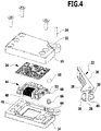
- FIG. 1 is a schematic representation of a first embodiment of a wireless switch according to the invention, which is given the reference numeral 10 overall. It comprises a cuboid housing 12 with a first housing half 14 and a second housing half 16, which can be joined together to form a parting plane 18.
- An actuating element configured as a double-armed pivoted lever 22 is held on the housing 12 so as to be pivotable about a pivot axis 20 aligned perpendicularly to the parting plane 18 .
- the pivoted lever 22 assumes a pivoted-out position and in figure 2 the pivoted lever 22 is shown in a pivoted-in position. In the pivoted-in position, the pivoted lever 22 rests against a longitudinal side 24 of the housing 12 .
- the pivoting lever 22 has a U-shaped cross section. It comprises two side walls 26, 28 which are connected to one another in one piece via a web 30. The two side walls 26, 28 are each arranged in a lateral recess 32 of the housing 12 and are connected to one another via a pivot pin 34.
- the pivot pin 34 extends through the two housing halves 14 and 16 and defines the pivot axis 20 of the pivot lever 22.
- a first lever arm 36 of the swivel lever 22 extends along the longitudinal side 24 of the housing 12, and a second lever arm 38 extends essentially perpendicularly to the first lever arm 36 and is positioned in the area of the lateral recesses 32.
- the two side walls 26, 28 are rigidly connected to one another in the region of the second lever arm 38 via a cross member 40.
- the pivoted lever 22 is resiliently biased into its pivoted-out position with the aid of a restoring spring, which is designed as a torsion spring 42 in the exemplary embodiment shown. Under the action of the torsion spring 42, the pivoting lever 22 can be pivoted from its pivoted-out position into its pivoted-in position.
- a restoring spring which is designed as a torsion spring 42 in the exemplary embodiment shown.
- the radio switch 10 is designed to be energy self-sufficient, so it does not require an external energy source. Instead, the wireless switch 10 has a voltage generator 44 for generating energy, which is accommodated in a recess 46 in the first housing half 14 and includes an induction coil 48 and a soft-iron rocker 50 on which an elastically deformable spring tongue 52 is fixed on one side. A permanent magnet passes through the induction coil 48 and is fixed in place in the first housing half 14 .
- the soft-iron rocker 50 has, in the usual way, two stable end positions in which it is attracted by the permanent magnet.
- a sudden pivoting movement of the soft iron rocker 50 relative to the induction coil 48 can be achieved by deforming the spring tongue 52 .
- the spring tongue 52 can increasingly move out of a spring level in which it is in the unloaded state, as in figure 4 shown, extends and which is aligned parallel or coplanar to the parting plane 18, are deformed.
- the spring tongue 52 reaches a predetermined degree of deformation, the soft-iron rocker 50 changes abruptly from its original end position to the other end position due to the acting spring force, and the spring tongue 52 relaxes.
- the abrupt movement of the soft-iron rocker 50 results in an electrical voltage being induced in the induction coil 48 .
- the wireless switch 10 has a transmitter assembly 54, which is accommodated in a recess, not shown in the drawing, in the second housing half 16 and which is positioned laterally next to the voltage generator 44.
- the transmitter assembly 54 is electrically connected to the induction coil 48 via electrical contact springs which are known per se and are therefore not shown in the drawing to achieve a better overview. This makes it possible to provide electrical energy to transmitter assembly 54 by activating voltage generator 44 using spring tongue 52. If electrical energy is made available to transmitter assembly 54, it generates a coded radio signal that is emitted via a radio antenna of transmitter assembly 54.
- a deformation of the spring tongue 52 is achieved by moving the pivoting lever 22 .
- the pivoting lever 22 has a control link 58 on the inner side 56 of the side wall 28 facing the side wall 26 .
- the control link 58 interacts with a force transmission element 60, which is spherical in the illustrated embodiment and is held in a guide shaft 62 of the second housing half 16 in the longitudinal direction of the guide shaft 62, i.e. parallel to the pivot axis 20 of the pivot lever 22.
- the first housing half 14 Aligned to the guide shaft 62, the first housing half 14 has a spring shaft 64 in which a compression spring 66 is positioned.
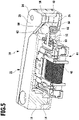
- a free spring end 68 of the spring tongue 52 is arranged between the force transmission element 60 and the compression spring 66 . This is made out in particular figure 5 clear.
- the control link 58 embodied in the manner of a ramp is positioned on the inside 56 of the side cheek 28 in such a way that it is at a distance from the force transmission element 60 when the pivoted lever 22 is in the pivoted-in position. If the pivoted lever 22 is moved into its pivoted-out position, the control link 58 approaches the spherical force transmission element 60 so far that it slides along the control link 58 and in the axial direction to the compression spring 66 is postponed. As a result, the spring tongue 52 is subjected to an activation force acting perpendicularly on it, so that it undergoes an increasing elastic deformation during a further pivoting movement of the pivot lever 22 .
- the soft-iron rocker 50 suddenly performs a rocking motion and the spring tongue 52 relaxes, with a voltage pulse being induced in the induction coil 48 .
- the control link 58 releases the spherical force transmission element, which is then pushed by the compression spring 66 in the direction of the side wall 28, so that the force applied to the spring tongue 52 is eliminated.
- the spring tongue 52 then resumes its original shape, in which the compression spring 66 now assumes the function of the force transmission element in the opposite direction and also induces a tension pulse in this end position of the spring tongue 52 .
- the spring tongue 52 thus performs a mirror-symmetrical interplay during the back and forth movement of the pivoted lever 22, with a radio signal being emitted in each of the two end positions.
- the radio switch 10 is particularly suitable for monitoring the movement of an object.
- the pivoted lever 22 can contact the object to be monitored in its pivoted-in position. If the object to be monitored is removed from the pivoting lever 22, the pivoting lever 22 performs a pivoting movement under the action of the torsion spring 42, and this in turn has the result that an electrical voltage is generated by means of the spring tongue 52 and the voltage generator 44, so that a coded radio signal can be emitted by the transmitter assembly 54 .
- the radio switch 10 has a very long service life and is characterized by a very compact design. It is particularly suitable as a built-in installation that can be integrated into a window or door frame, for example, to monitor a window or door. In the same way, the radio switch 10 can also be used to monitor other objects be used, for example, to monitor containers, drawers, flaps, strips, protective grilles, covers, facade elements, cables, belts, bearing blocks and machine elements.
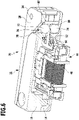
- FIG 6 a second embodiment of a wireless switch according to the invention is shown, which is assigned the reference number 70 overall.
- the radio switch 70 like the radio switches 90, 110, 120, 130, 140, 170 and 210 explained below, is configured largely identically to the one described above with reference to FIG Figures 1 to 5 explained radio switch 10.
- the same reference numbers are used as in FIGS Figures 1 to 5 and with regard to these components, to avoid repetition, reference is made to the above explanations.
- the radio switch 10 differs from the in figure 6 Illustrated wireless switch 70 in that it has a first force transmission element 72 and a second force transmission element 74, which are each spherical and are arranged in a guide shaft 76 extending through the housing 12 parallel to the pivot axis 20.
- the spring end 68 of the spring tongue 52 dips laterally into the guide shaft 76 so that the latter is divided by the spring tongue 52 into a first shaft area 78 and a second shaft area 80 .
- a force transmission element 72 or 74 is arranged in each of the two shaft areas 78, 80 .
- a further difference between the radio switch 10 and the radio switch 70 is that in the radio switch 70 a control link is arranged both on the inside of the side panel 28 and on the inside of the side panel 26 .
- the second control link is positioned offset in the pivoting direction of the pivoting lever 22 to the first control link 82 on the inside of the side panel 26 .
- the force transmission elements 72 and 74 can be displaced in mutually opposite directions along the guide shaft 76 via the control links will.
- the second control link (not shown in the drawing) assigned to the second force-transmission element 74 first releases the second force-transmission element 74, so that it can move freely in the second shaft area 80, and with a further pivoting movement meets the first control link 82 on the first force transmission element 72, so that this is pushed in the direction of the spring tongue 52 and thereby the spring tongue 52 bends.
- the bending process of the spring tongue 52 is in no way impaired by the second force transmission element 74 .
- the spring tongue 52 reaches a predetermined degree of deformation when the pivoted lever 22 is pivoted out under the action of the first force transmission element 72, it suddenly relaxes and a voltage pulse is induced in the induction coil 48 in the manner already explained above, under the effect of which the transmitter assembly 54 generates a coded radio signal is emitted.
- the first control link 82 first releases the first force-transmitting element 72 and then the second control link strikes the second force-transmitting element 74, so that this moves in the direction is moved onto the spring tongue 52 and thereby the spring tongue 52 bends until a predetermined degree of deformation is reached.
- a voltage pulse is generated, which causes the transmitter assembly 54 to emit a coded radio signal.
- a back and forth movement of the pivoted lever 22 thus results in the radio switch 70 in that two radio signals are emitted one after the other.
- FIG 7 is shown schematically in the form of a perspective partial representation of an embodiment of a wireless switch, the total with the Reference number 90 is occupied.
- the round pins each have convex contact surfaces 96 facing one another, which rest on one side of the spring tongue 52 in each case.
- the two force transmission elements 92, 94 each interact with a control link 102 or 104, which is arranged on the insides of the side cheeks 26 and 28 of the pivoted lever 22 of the radio switch 90.
- the two control links 102, 104 are offset from each other in the direction of movement of the pivoted lever 22, so that one of the two force transmission elements 92, 94 is freely movable when the other force transmission element slides along the associated control link.
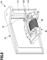
- FIG 8 an embodiment of a wireless switch is shown schematically, which is assigned the reference numeral 110 overall. It differs from the radio switch 90 explained above in that, instead of cylindrical force transmission elements, two force transmission elements 112, 114 are used, each of which is in the form of a square. In contrast to the power transmission elements 92, 94 of the radio switch 90, the power transmission elements 112, 114 of the radio switch 110 are guided in a square guide shaft of the housing 12 so that they cannot rotate.
- the force transmission elements 112, 114 also have convex contact surfaces 116 facing one another, with which they can be placed against the spring tongue 52.
- the convex contact surfaces 116 ensure that only normal forces can be exerted on the spring tongue 52 by the force transmission elements 112 , 114 during a pivoting movement of the pivoted lever 22 .
- FIG 9 an embodiment of a wireless switch is shown schematically, which is assigned the reference numeral 120 overall.
- the wireless switch 120 uses only a single force transmission element 122, which is arranged between the two side walls 26, 28 of the pivoted lever 22 and which has a recess in the form of an external annular groove at the level of the spring tongue 52 124 has.
- the free spring end 68 of the spring tongue 52 dips into the annular groove 124 .
- the power transmission element 122 of the radio switch 120 is also slidably mounted in a guide shaft of the housing 12 and can be moved back and forth in the guide shaft with the aid of control links 126, 128 arranged on the insides of the side walls 26, 28 when the pivoted lever 22 moves a back and forth continuous pivoting movement.
- FIG 10 1 is a schematic representation of an embodiment of a wireless switch, which is assigned the reference number 130 overall.
- the radio switch 130 is largely identical in design to the radio switch 120, with only a single force transmission element 132 being used. While the force transmission element 122 of the radio switch 120 is cylindrical and can be rotated about the longitudinal axis of the shaft in the associated guide shaft, the force transmission element 132 of the radio switch 130 is designed in the manner of a square and is held non-rotatably in the associated guide shaft of the housing 12 .
- the force transmission element 132 has on its side facing the spring tongue 52 a slot-shaped recess 134 into which the free spring end 68 of the spring tongue 52 dips.
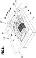
- the pivoted lever 22 which is mounted on the housing 12 so that it can pivot about a pivot axis 20 perpendicular to the parting plane 18 and can therefore be moved in the parting plane 18.
- Pivoting bracket 142 is designed as a self-contained wire bracket and comprises a first bracket part 144 running along three outer sides of housing 12 and a second bracket part 146 reaching through housing 12.
- First bracket part 144 is U-shaped and integral with second bracket part 146 tied together.
- the second bracket part 146 defines a pivot axis 152 of the pivot bracket 142 with its end sections 148 and 150 facing the first bracket part 144, which are aligned with one another.
- the pivot axis 152 is aligned parallel to the parting plane 18 of the two housing halves 14, 16 of the housing 12.
- the second bracket part 146 has an offset bracket part section 154, which defines a central section 156 running parallel to the end sections 148, 150.
- a force transmission element 158 is slidably held on the central section 156 and has a slot-shaped recess 160 on its side facing away from the central section 156 .
- the free spring end 68 of the spring tongue 52 dips into the slot-shaped recess 160 of the force transmission element 158 .
- a restoring spring 162 is arranged laterally next to the force-transmitting element 148 and acts on the middle section 156 with a spring force, thereby predetermining a specific pivoting position for the pivoting bracket 142 . From this pivoting position, which in figure 11 is shown, the swivel bar can be swiveled against the action of the return spring 162 .
- the end region of the force transmission element 158 facing away from the middle section 156 enters a guide shaft 164 of the first housing half 14 and is held in the guide shaft 164 so that it cannot rotate.
- pivot bar 142 is pivoted about pivot axis 152 counter to the action of return spring 162, force transmission element 158 executes a movement perpendicular to parting plane 18 and spring tongue 52 is increasingly deformed in a corresponding manner, as has already been explained in detail above that it suddenly relaxes when a predetermined degree of deformation is reached and a coded radio signal can be emitted by the radio switch 140 .
- the radio switches 10, 70, 90, 110, 120, 130 and 140 explained above are designed as pivoting or toggle switches, in that they each have an actuating element which can be pivoted about a pivot axis.
- An embodiment of a radio switch according to the invention is shown schematically, which is given the overall reference number 170 and which forms a slide switch.
- the radio switch 170 has a cuboid housing 172 with two housing halves 174, 176 which define a parting plane 178 between them.
- the housing 172 of the wireless switch 170 also accommodates a voltage generator 44 with a spring tongue 52 and a transmitter assembly 54, wherein the spring tongue 52 can be acted upon by two identically designed, spherical force transmission elements with an activation force aligned perpendicularly to the spring tongue 52 is.
- a voltage generator 44 with a spring tongue 52 and a transmitter assembly 54
- the spring tongue 52 can be acted upon by two identically designed, spherical force transmission elements with an activation force aligned perpendicularly to the spring tongue 52 is.
- the two spherical power transmission elements of the wireless switch 170 are arranged in a guide shaft 180 that extends through the housing 172 .
- the guide shaft 180 is in figure 14 recognizable.
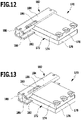
- the wireless switch 170 has a sliding part 182 which is U-shaped in cross section and includes two side walls 184, 186 which are connected to one another in one piece via a web 188.
- the sliding part 182 can be linearly displaced along a guide section 190 of the housing 172 .
- the guide portion 190 faces each other
- a guide groove 192 or 194 is provided on each of the outer sides of the housing facing away from it, into which the free ends of the side walls 184, 186, which are bent inward, dip.
- the side panels 184, 186 each have an elongated hole 196, 198.
- the elongated holes 196, 198 are offset from one another in the longitudinal direction of the sliding part 182 and their edges each form a control link for a force transmission element arranged in the guide shaft 180.
- the width of the elongated holes 196, 198 is selected to be smaller than the diameter of the spherical force transmission elements, so that they can only dip into the elongated holes 196, 198 with a spherical cap 200, provided that the respective elongated hole 196, 198 is in a position aligned with the guide shaft 180.
- the sliding part 182 can be positioned between an in figure 12 shown first switching position and in figure 13 shown second switching position to be shifted back and forth.
- the elongated hole 196 in the first side cheek 184 is offset from the guide shaft 180, so that the spherical force-transmitting element associated with this elongated hole 196 is pressed by the first side cheek 184 in the direction of the spring tongue 52, which under the action of the force acting perpendicularly on it activating force of the force transmission element is deformed so much that it abruptly relaxes after the predetermined degree of deformation is exceeded and an electrical voltage is thereby induced by the voltage generator 44 in the manner already explained above and a coded radio signal is emitted by the transmitter assembly 54.
- the slot 198 of the second side wall 186 is aligned with the guide shaft 180, so that the spherical force transmission element assigned to the slot 198 can move with its spherical cap into the slot 198 and thus does not impair the deformation of the spring tongue 52 in any way .
- a displacement of the sliding part 192 along the guide section 190 parallel to the parting plane 178 of the two housing halves 174, 176 thus leads to a forced movement of one of the two force transmission elements perpendicular to the parting plane 178, so that the spring tongue 52 can be subjected to an activation force acting perpendicularly on it.
- the sliding part 182 is automatically returned to the in figure 12 shown first switching position biased and can be moved against the action of the return spring 202 in the second switching position.
- the radio switch 170 thus forms a push button switch.
- FIG 16 an embodiment of a wireless switch according to the invention is shown, which is assigned the reference number 210 overall. This is largely identical in design to that described above with reference to FIG Figures 1 to 10 illustrated embodiments.
- the wireless switch 210 differs from these in that, instead of a pivoting lever, an actuating element in the form of a double wheel 202 is used, which is mounted on the housing 12 so that it can rotate freely about an axis of rotation 204 .
- the double wheel 202 has two side cheeks in the form of a first wheel disk 206 and a second wheel disk 208 which are rigidly connected to one another via a web 210 aligned collinearly with the axis of rotation 204 .
- the two wheel discs 206, 208 are in a corresponding manner as the side cheeks 26, 28 of the pivoting lever explained above 22 are each arranged in a lateral recess 32 of the housing 12 .
- the housing 12 of the wireless switch 210 is penetrated in a manner corresponding to the housing 12 by a guide shaft in which a first force transmission element and a second force transmission element are arranged.
- the spring tongue of the wireless switch 210 can be deformed by means of the two force transmission elements to generate a wireless signal in the manner already explained above.
- the two wheel discs 206, 208 are crenellated on their circumferences as a tooth-gap outline.
- the two wheel discs 206, 208 each have four teeth 212, 214, 216, 218 protruding radially outwards, with the two wheel discs 206, 208 being rotated by half a tooth pitch in relation to one another.
- the flanks of the teeth 212, 214, 216 and 218 each act as a control link which interacts with the spherical force transmission elements.
- the force transmission elements of wireless switch 210 When double wheel 202 rotates, the force transmission elements of wireless switch 210 perform an oscillating movement, with one of the two force transmission elements being displaced in the direction of the spring tongue, while the other force transmission element can enter a gap between two teeth on the other wheel disk.
- the radio switch 210 thus forms an endlessly rotatable rotary switch.
- the double wheel 202 can be actuated, for example, with the aid of a toothed rack, a ring gear or a belt drive, as well as with helical and bevel gears and also with worm gears, which allow torque to be transmitted between crossing wheel axles. Provision can be made for the double wheel 202 to be connected in a torque-proof manner to a hollow shaft which has a wrench flat.
Landscapes
- Engineering & Computer Science (AREA)
- Power Engineering (AREA)
- Mechanisms For Operating Contacts (AREA)
- Input Circuits Of Receivers And Coupling Of Receivers And Audio Equipment (AREA)
- Burglar Alarm Systems (AREA)
Claims (15)
- Commutateur radio comprenant un boîtier (12), dans lequel sont agencés un générateur de tension (44) pourvu d'une languette flexible (52) déformable élastiquement et un module émetteur (54), dans lequel le module émetteur (54) peut être soumis par le générateur de tension (44) à l'effet d'une énergie électrique pour la génération d'un signal radio, et comprenant un élément d'actionnement (22 ; 142 ; 182 ; 202) qui peut être déplacé par rapport à la languette flexible et qui est accouplé à la languette flexible (52) pour l'activation du générateur de tension (44), dans lequel l'élément d'actionnement (22 ; 142 ; 182 ; 202) est monté sur le boîtier (12 ; 172) de manière à pouvoir se déplacer en rotation ou en translation et est accouplé à la languette flexible (52) par l'intermédiaire d'au moins un élément de transmission de force (60 ; 72, 74 ; 92, 94 ; 112, 114 ; 122 ; 132 ; 158), et dans lequel la languette flexible (52), lors d'un déplacement de l'élément d'actionnement (22 ; 142 ; 182 ; 202), peut être soumis à l'effet d'une force d'activation orientée perpendiculairement à la languette flexible (52) par un élément de transmission de force (60 ; 72, 74 ; 92, 94 ; 112, 114 ; 122 ; 132 ; 158) par l'intermédiaire d'une surface de contact, caractérisé en ce que l'élément ou les éléments de transmission de force (60 ; 72, 74) sont sphériques.
- Commutateur radio selon la revendication 1, caractérisé en ce que la languette flexible (52), dans l'état non sollicité, s'étend dans un plan de ressort et en ce que l'élément ou les éléments de transmission de force (60 ; 72, 74 ; 92, 94 ; 112, 114 ; 122 ; 132 ; 158) sont montés dans le boîtier (12 ; 172) de manière à pouvoir coulisser le long d'un axe orienté perpendiculairement au plan de ressort.
- Commutateur radio selon la revendication 1 ou 2, caractérisé en ce que l'élément d'actionnement (22 ; 142 ; 182 ; 202) est accouplé à l'élément ou aux éléments de transmission de force (60 ; 72, 74 ; 92, 94 ; 112, 114 ; 122 ; 132 ; 158) par l'intermédiaire d'au moins une coulisse de commande (58 ; 82 ; 102, 104 ; 126, 128 ; 196, 198).
- Commutateur radio selon l'une quelconque des revendications précédentes, caractérisé en ce que l'élément ou les éléments de transmission de force (60 ; 158) peuvent être déplacés en direction de la languette flexible (52) à l'encontre de l'action d'une force de rappel élastique.
- Commutateur radio selon la revendication 4, caractérisé en ce que la languette flexible (52) présente deux faces plates opposées l'une à l'autre, dans lequel un élément de transmission de force (60) s'applique contre une face et un ressort de compression (66) s'applique contre l'autre face.
- Commutateur radio selon l'une quelconque des revendications précédentes, caractérisé en ce que l'élément ou les éléments de transmission de force (60 ; 72, 74 ; 92, 94 ; 112, 114 ; 122 ; 132 ; 158) sont guidés de manière à pouvoir coulisser linéairement dans un organe de guidage.
- Commutateur radio selon la revendication 6, caractérisé en ce qu'au moins un organe de guidage est réalisé sous la forme d'un puits de guidage (62 ; 76 ; 180), dans lequel au moins un élément de transmission de force (60 ; 72, 74 ; 92, 94 ; 112, 114 ; 122 ; 132 ; 158) est guidé de manière à pouvoir coulisser linéairement.
- Commutateur radio selon la revendication 7, caractérisé en ce que le boîtier (12 ; 172) forme au moins un puits de guidage (62 ; 76 ; 180).
- Commutateur radio selon l'une quelconque des revendications précédentes, caractérisé en ce que le commutateur radio (70 ; 90 ; 110 ; 170 ; 210) présente deux éléments de transmission de force (72, 74 ; 92, 94 ; 112, 114), qui soumettent la languette flexible (52) en alternance à l'effet de forces d'activation dirigées les unes à l'encontre des autres.
- Commutateur radio selon la revendication 9, caractérisé en ce que l'élément d'actionnement (22 ; 182) comprend deux coulisses de commande (102, 104 ; 126, 128 ; 196, 198) contre lesquelles respectivement un élément de transmission de force (72, 74 ; 92, 94 ; 112, 114) peut s'appliquer en glissant.
- Commutateur radio selon la revendication 10, caractérisé en ce que les deux coulisses de commande (102, 104 ; 126, 128) sont décalées l'une de l'autre dans la direction de déplacement de l'élément d'actionnement (22 ; 182).
- Commutateur radio selon la revendication 10 ou 11, caractérisé en ce que l'élément d'actionnement (22 ; 182) peut être déplacé en va-et-vient entre deux positions d'extrémité, dans lequel lors d'un déplacement de l'élément d'actionnement (22 ; 182) d'une position d'extrémité dans l'autre position d'extrémité, respectivement un des deux éléments de transmission de force (72, 74 ; 92, 94 ; 112, 114) peut être soumis à l'effet d'une force en direction de la languette élastique (52) par une des deux coulisses de commande (102, 104 ; 126, 128 ; 196, 198) et l'autre élément de transmission de force (72, 74 ; 92, 94 ; 112, 114) peut être libéré par l'autre coulisse de commande (102, 104 ; 126, 128 ; 196, 198).
- Commutateur radio selon l'une quelconque des revendications précédentes, caractérisé en ce que le boîtier (12 ; 172) comprend deux moitiés de boîtier (14, 16 ; 174, 176), qui définissent entre elles un plan de séparation (18 ; 178) orienté de manière parallèle ou coplanaire par rapport à la languette flexible (52) non sollicitée, et en ce que l'élément d'actionnement (22 ; 142 ; 182 ; 202) est monté sur le boîtier (12 ; 172) de manière à pouvoir se déplacer autour d'un axe de rotation ou de pivotement orienté parallèlement ou perpendiculairement au plan de séparation (18 ; 178) ou le long d'un axe de coulissement orienté parallèlement au plan de séparation (18 ; 178).
- Commutateur radio selon la revendication 13, caractérisé en ce que l'élément d'actionnement (22 ; 182 ; 202) présente deux joues latérales (26, 28 ; 184, 186 ; 206, 208), qui sont reliées l'une à l'autre par un élément jointif (30 ; 188 ; 210), dans lequel les joues latérales (26, 28 ; 184, 186 ; 206, 208) présentent sur leurs faces tournées les unes vers les autres respectivement une coulisse de commande (102, 104 ; 126, 128), dans lequel une force orientée perpendiculairement à la direction de déplacement de l'élément d'actionnement (22 ; 182 ; 202) peut être transmise sur au moins un élément de transmission de force (72, 74 ; 92, 94 ; 112, 114 ; 122 ; 132 ; 158) par l'intermédiaire des coulisses de commande (102, 104 ; 126, 128).
- Commutateur radio selon la revendication 14, caractérisé en ce que l'élément d'actionnement est réalisé sous la forme d'un levier pivotant (22) monté pivotant sur le boîtier.
Applications Claiming Priority (1)
| Application Number | Priority Date | Filing Date | Title |
|---|---|---|---|
| DE102012112897.9A DE102012112897A1 (de) | 2012-12-21 | 2012-12-21 | Funkschalter |
Publications (3)
| Publication Number | Publication Date |
|---|---|
| EP2747111A1 EP2747111A1 (fr) | 2014-06-25 |
| EP2747111B1 EP2747111B1 (fr) | 2018-09-19 |
| EP2747111B2 true EP2747111B2 (fr) | 2022-06-15 |
Family
ID=49880434
Family Applications (1)
| Application Number | Title | Priority Date | Filing Date |
|---|---|---|---|
| EP13197975.9A Active EP2747111B2 (fr) | 2012-12-21 | 2013-12-18 | Commutateur radio |
Country Status (3)
| Country | Link |
|---|---|
| EP (1) | EP2747111B2 (fr) |
| DE (1) | DE102012112897A1 (fr) |
| ES (1) | ES2701079T5 (fr) |
Families Citing this family (7)
| Publication number | Priority date | Publication date | Assignee | Title |
|---|---|---|---|---|
| DE102014209192A1 (de) | 2014-05-15 | 2015-11-19 | Zf Friedrichshafen Ag | Schaltvorrichtung für einen Funktaster, Funktaster und Verfahren zum Erzeugen eines Schaltsignals eines Funktasters |
| JP6558048B2 (ja) * | 2015-04-24 | 2019-08-14 | ミツミ電機株式会社 | 発電スイッチ |
| CN104883025B (zh) * | 2015-06-12 | 2019-08-20 | 武汉领普科技有限公司 | 自复位发电装置及开关 |
| DE202016101805U1 (de) | 2016-04-06 | 2016-04-26 | Engeltech Gmbh | Auslösevorrichtung eines Funkschalters |
| CN112187096A (zh) * | 2017-04-01 | 2021-01-05 | 广东易百珑智能科技有限公司 | 可变更按键数目的无源回弹式开关 |
| CN111049352B (zh) * | 2018-07-11 | 2023-03-14 | 广东易百珑智能科技有限公司 | 循环分解装置和循环发电装置及循环分解方法 |
| CN111817527A (zh) * | 2020-07-29 | 2020-10-23 | 广东易百珑智能科技有限公司 | 拨动式发电装置及其方法和电子设备 |
Citations (4)
| Publication number | Priority date | Publication date | Assignee | Title |
|---|---|---|---|---|
| DE3729357A1 (de) † | 1987-09-02 | 1989-03-16 | Sasse Eugen Bauelemente | Schalter |
| DE9013310U1 (de) † | 1990-09-20 | 1990-11-29 | Burgess GmbH, 2900 Oldenburg | Elektrischer Schalter, insbesondere Kleinstschalter, mit einem Betätigungshebel |
| DE10325880A1 (de) † | 2002-06-07 | 2004-01-08 | Exedy Corp., Neyagawa | Dämfperscheibenanordnung |
| DE102010003152A1 (de) † | 2010-03-23 | 2011-09-29 | Zf Friedrichshafen Ag | Funkschalter |
Family Cites Families (7)
| Publication number | Priority date | Publication date | Assignee | Title |
|---|---|---|---|---|
| US3809837A (en) * | 1971-09-30 | 1974-05-07 | Matsushita Electric Works Ltd | Microswitch with readily removable leaf spring actuating means |
| CH552888A (de) * | 1972-04-11 | 1974-08-15 | Siegrist W Sibalco & Co | Schalter mit mindestens einem schutzrohrkontakt und einem permanentmagnet. |
| DE3210033A1 (de) * | 1982-03-19 | 1983-09-22 | Eckerfeld, Erika, 5628 Heiligenhaus | Mikroschalter |
| DE3614006A1 (de) * | 1986-04-25 | 1987-10-29 | Heidelberger Druckmasch Ag | Druckmaschine, insbesondere bogenoffsetdruckmaschine |
| GB9505045D0 (en) * | 1995-03-13 | 1995-05-03 | Ashley & Rock Ltd | Electric switch |
| FR2893780A1 (fr) * | 2005-11-22 | 2007-05-25 | Schneider Electric Ind Sas | Dispositif autonome de generation d'energie electrique |
| EP2550725B1 (fr) * | 2010-03-23 | 2014-12-24 | ZF Friedrichshafen AG | Generateur a induction |
-
2012
- 2012-12-21 DE DE102012112897.9A patent/DE102012112897A1/de not_active Withdrawn
-
2013
- 2013-12-18 ES ES13197975T patent/ES2701079T5/es active Active
- 2013-12-18 EP EP13197975.9A patent/EP2747111B2/fr active Active
Patent Citations (4)
| Publication number | Priority date | Publication date | Assignee | Title |
|---|---|---|---|---|
| DE3729357A1 (de) † | 1987-09-02 | 1989-03-16 | Sasse Eugen Bauelemente | Schalter |
| DE9013310U1 (de) † | 1990-09-20 | 1990-11-29 | Burgess GmbH, 2900 Oldenburg | Elektrischer Schalter, insbesondere Kleinstschalter, mit einem Betätigungshebel |
| DE10325880A1 (de) † | 2002-06-07 | 2004-01-08 | Exedy Corp., Neyagawa | Dämfperscheibenanordnung |
| DE102010003152A1 (de) † | 2010-03-23 | 2011-09-29 | Zf Friedrichshafen Ag | Funkschalter |
Also Published As
| Publication number | Publication date |
|---|---|
| DE102012112897A1 (de) | 2014-07-10 |
| ES2701079T5 (es) | 2022-08-19 |
| EP2747111A1 (fr) | 2014-06-25 |
| EP2747111B1 (fr) | 2018-09-19 |
| ES2701079T3 (es) | 2019-02-20 |
Similar Documents
| Publication | Publication Date | Title |
|---|---|---|
| EP2747111B2 (fr) | Commutateur radio | |
| EP2308347B1 (fr) | Poussoir pour un élément de meuble mobile | |
| EP2841667B1 (fr) | Entrainement pour porte pivotante | |
| EP2755804B1 (fr) | Machine outil motorisée | |
| AT510017B1 (de) | Ausstossvorrichtung für ein bewegbares möbelteil | |
| EP3336292B1 (fr) | Procédé d'actionnement d'une serrure de porte et serrure de porte | |
| EP1817983A1 (fr) | Dispositif pour influencer le mouvement des parties de meuble l'une par rapport à l'autre et une glissière pour tiroirs, ainsi qu'un procédé de fabrication d'un tel dispositif | |
| DE19500944A1 (de) | Antrieb für einen Flügel einer Tür, Fenster oder dergleichen | |
| EP2933414A1 (fr) | Entraînement de porte | |
| DE3011706A1 (de) | Wellen-endschalter | |
| EP1416832B1 (fr) | Entrainement de meuble destine a deplacer des elements d'un meuble les uns par rapport aux autres | |
| EP3095942B1 (fr) | Dispositif d'entraînement de porte pivotante | |
| EP1853136B1 (fr) | Meuble reglable servant de siege | |
| DE3610772C1 (de) | Kleines Haushaltsgeraet,das mittels eines Einphasensynchronmotors angetrieben ist | |
| DE945770C (de) | Verfahren zur Herstellung elektrischer Schalter, die aus einzelnen Schalterelementenmit den inneren Schalterteilen zu einer Einheit zusammengebaut sind | |
| EP2159358B1 (fr) | Verrou pour un composant destiné à la fermeture d'une ouverture | |
| DE102004001511B4 (de) | Vorrichtung zum Arretieren einer Lenksäule eines Kraftfahrzeuges | |
| DE102009058678B4 (de) | Verstellvorrichtung zum Verstellen, insbesondere zum translatorischen Verschieben, wenigstens eines Möbelteils | |
| EP0943762A2 (fr) | Dispositif de verrouillage / deverrouillage avec une codage mécanique et électrique | |
| EP4112856B1 (fr) | Serrure dotée d'un verrou pouvant tourner à l'aide d'un élément d'actionnement | |
| DE102022208524B4 (de) | Feststelleinrichtung sowie Türantrieb | |
| DE4143158A1 (de) | Vorrichtung zur begrenzung des wischwinkels einer scheibenwischanlage | |
| EP4650553A1 (fr) | Ferrure de fenêtre ou de porte | |
| DE3905247C2 (de) | Feststellvorrichtung für einen schwenkbaren Flügel einer Tür, mit einem Schließmittel | |
| DE102009020141A1 (de) | Vorrichtung zur gegenseitigen Verriegelung zweier Schalter, insbesondere Leistungsschalter |
Legal Events
| Date | Code | Title | Description |
|---|---|---|---|
| PUAI | Public reference made under article 153(3) epc to a published international application that has entered the european phase |
Free format text: ORIGINAL CODE: 0009012 |
|
| 17P | Request for examination filed |
Effective date: 20131218 |
|
| AK | Designated contracting states |
Kind code of ref document: A1 Designated state(s): AL AT BE BG CH CY CZ DE DK EE ES FI FR GB GR HR HU IE IS IT LI LT LU LV MC MK MT NL NO PL PT RO RS SE SI SK SM TR |
|
| AX | Request for extension of the european patent |
Extension state: BA ME |
|
| R17P | Request for examination filed (corrected) |
Effective date: 20141218 |
|
| RBV | Designated contracting states (corrected) |
Designated state(s): AL AT BE BG CH CY CZ DE DK EE ES FI FR GB GR HR HU IE IS IT LI LT LU LV MC MK MT NL NO PL PT RO RS SE SI SK SM TR |
|
| RAP1 | Party data changed (applicant data changed or rights of an application transferred) |
Owner name: ELTAKO GMBH |
|
| GRAP | Despatch of communication of intention to grant a patent |
Free format text: ORIGINAL CODE: EPIDOSNIGR1 |
|
| STAA | Information on the status of an ep patent application or granted ep patent |
Free format text: STATUS: GRANT OF PATENT IS INTENDED |
|
| INTG | Intention to grant announced |
Effective date: 20180416 |
|
| GRAS | Grant fee paid |
Free format text: ORIGINAL CODE: EPIDOSNIGR3 |
|
| GRAA | (expected) grant |
Free format text: ORIGINAL CODE: 0009210 |
|
| STAA | Information on the status of an ep patent application or granted ep patent |
Free format text: STATUS: THE PATENT HAS BEEN GRANTED |
|
| AK | Designated contracting states |
Kind code of ref document: B1 Designated state(s): AL AT BE BG CH CY CZ DE DK EE ES FI FR GB GR HR HU IE IS IT LI LT LU LV MC MK MT NL NO PL PT RO RS SE SI SK SM TR |
|
| REG | Reference to a national code |
Ref country code: GB Ref legal event code: FG4D Free format text: NOT ENGLISH |
|
| REG | Reference to a national code |
Ref country code: CH Ref legal event code: EP Ref country code: CH Ref legal event code: NV Representative=s name: ISLER AND PEDRAZZINI AG, CH |
|
| REG | Reference to a national code |
Ref country code: AT Ref legal event code: REF Ref document number: 1044194 Country of ref document: AT Kind code of ref document: T Effective date: 20181015 |
|
| REG | Reference to a national code |
Ref country code: IE Ref legal event code: FG4D Free format text: LANGUAGE OF EP DOCUMENT: GERMAN |
|
| REG | Reference to a national code |
Ref country code: DE Ref legal event code: R096 Ref document number: 502013011107 Country of ref document: DE |
|
| REG | Reference to a national code |
Ref country code: NL Ref legal event code: MP Effective date: 20180919 |
|
| REG | Reference to a national code |
Ref country code: SE Ref legal event code: TRGR |
|
| PG25 | Lapsed in a contracting state [announced via postgrant information from national office to epo] |
Ref country code: LT Free format text: LAPSE BECAUSE OF FAILURE TO SUBMIT A TRANSLATION OF THE DESCRIPTION OR TO PAY THE FEE WITHIN THE PRESCRIBED TIME-LIMIT Effective date: 20180919 Ref country code: RS Free format text: LAPSE BECAUSE OF FAILURE TO SUBMIT A TRANSLATION OF THE DESCRIPTION OR TO PAY THE FEE WITHIN THE PRESCRIBED TIME-LIMIT Effective date: 20180919 Ref country code: GR Free format text: LAPSE BECAUSE OF FAILURE TO SUBMIT A TRANSLATION OF THE DESCRIPTION OR TO PAY THE FEE WITHIN THE PRESCRIBED TIME-LIMIT Effective date: 20181220 Ref country code: FI Free format text: LAPSE BECAUSE OF FAILURE TO SUBMIT A TRANSLATION OF THE DESCRIPTION OR TO PAY THE FEE WITHIN THE PRESCRIBED TIME-LIMIT Effective date: 20180919 Ref country code: NO Free format text: LAPSE BECAUSE OF FAILURE TO SUBMIT A TRANSLATION OF THE DESCRIPTION OR TO PAY THE FEE WITHIN THE PRESCRIBED TIME-LIMIT Effective date: 20181219 Ref country code: BG Free format text: LAPSE BECAUSE OF FAILURE TO SUBMIT A TRANSLATION OF THE DESCRIPTION OR TO PAY THE FEE WITHIN THE PRESCRIBED TIME-LIMIT Effective date: 20181219 |
|
| REG | Reference to a national code |
Ref country code: LT Ref legal event code: MG4D |
|
| REG | Reference to a national code |
Ref country code: ES Ref legal event code: FG2A Ref document number: 2701079 Country of ref document: ES Kind code of ref document: T3 Effective date: 20190220 |
|
| PG25 | Lapsed in a contracting state [announced via postgrant information from national office to epo] |
Ref country code: LV Free format text: LAPSE BECAUSE OF FAILURE TO SUBMIT A TRANSLATION OF THE DESCRIPTION OR TO PAY THE FEE WITHIN THE PRESCRIBED TIME-LIMIT Effective date: 20180919 Ref country code: HR Free format text: LAPSE BECAUSE OF FAILURE TO SUBMIT A TRANSLATION OF THE DESCRIPTION OR TO PAY THE FEE WITHIN THE PRESCRIBED TIME-LIMIT Effective date: 20180919 Ref country code: AL Free format text: LAPSE BECAUSE OF FAILURE TO SUBMIT A TRANSLATION OF THE DESCRIPTION OR TO PAY THE FEE WITHIN THE PRESCRIBED TIME-LIMIT Effective date: 20180919 |
|
| PG25 | Lapsed in a contracting state [announced via postgrant information from national office to epo] |
Ref country code: CZ Free format text: LAPSE BECAUSE OF FAILURE TO SUBMIT A TRANSLATION OF THE DESCRIPTION OR TO PAY THE FEE WITHIN THE PRESCRIBED TIME-LIMIT Effective date: 20180919 Ref country code: RO Free format text: LAPSE BECAUSE OF FAILURE TO SUBMIT A TRANSLATION OF THE DESCRIPTION OR TO PAY THE FEE WITHIN THE PRESCRIBED TIME-LIMIT Effective date: 20180919 Ref country code: NL Free format text: LAPSE BECAUSE OF FAILURE TO SUBMIT A TRANSLATION OF THE DESCRIPTION OR TO PAY THE FEE WITHIN THE PRESCRIBED TIME-LIMIT Effective date: 20180919 Ref country code: IS Free format text: LAPSE BECAUSE OF FAILURE TO SUBMIT A TRANSLATION OF THE DESCRIPTION OR TO PAY THE FEE WITHIN THE PRESCRIBED TIME-LIMIT Effective date: 20190119 Ref country code: EE Free format text: LAPSE BECAUSE OF FAILURE TO SUBMIT A TRANSLATION OF THE DESCRIPTION OR TO PAY THE FEE WITHIN THE PRESCRIBED TIME-LIMIT Effective date: 20180919 Ref country code: PL Free format text: LAPSE BECAUSE OF FAILURE TO SUBMIT A TRANSLATION OF THE DESCRIPTION OR TO PAY THE FEE WITHIN THE PRESCRIBED TIME-LIMIT Effective date: 20180919 |
|
| PG25 | Lapsed in a contracting state [announced via postgrant information from national office to epo] |
Ref country code: SK Free format text: LAPSE BECAUSE OF FAILURE TO SUBMIT A TRANSLATION OF THE DESCRIPTION OR TO PAY THE FEE WITHIN THE PRESCRIBED TIME-LIMIT Effective date: 20180919 Ref country code: SM Free format text: LAPSE BECAUSE OF FAILURE TO SUBMIT A TRANSLATION OF THE DESCRIPTION OR TO PAY THE FEE WITHIN THE PRESCRIBED TIME-LIMIT Effective date: 20180919 Ref country code: PT Free format text: LAPSE BECAUSE OF FAILURE TO SUBMIT A TRANSLATION OF THE DESCRIPTION OR TO PAY THE FEE WITHIN THE PRESCRIBED TIME-LIMIT Effective date: 20190119 |
|
| REG | Reference to a national code |
Ref country code: DE Ref legal event code: R026 Ref document number: 502013011107 Country of ref document: DE |
|
| PLBI | Opposition filed |
Free format text: ORIGINAL CODE: 0009260 |
|
| PLAX | Notice of opposition and request to file observation + time limit sent |
Free format text: ORIGINAL CODE: EPIDOSNOBS2 |
|
| 26 | Opposition filed |
Opponent name: ZF FRIEDRICHSHAFEN AG Effective date: 20190619 |
|
| PG25 | Lapsed in a contracting state [announced via postgrant information from national office to epo] |
Ref country code: DK Free format text: LAPSE BECAUSE OF FAILURE TO SUBMIT A TRANSLATION OF THE DESCRIPTION OR TO PAY THE FEE WITHIN THE PRESCRIBED TIME-LIMIT Effective date: 20180919 |
|
| GBPC | Gb: european patent ceased through non-payment of renewal fee |
Effective date: 20181219 |
|
| PG25 | Lapsed in a contracting state [announced via postgrant information from national office to epo] |
Ref country code: MC Free format text: LAPSE BECAUSE OF FAILURE TO SUBMIT A TRANSLATION OF THE DESCRIPTION OR TO PAY THE FEE WITHIN THE PRESCRIBED TIME-LIMIT Effective date: 20180919 Ref country code: LU Free format text: LAPSE BECAUSE OF NON-PAYMENT OF DUE FEES Effective date: 20181218 |
|
| REG | Reference to a national code |
Ref country code: IE Ref legal event code: MM4A |
|
| REG | Reference to a national code |
Ref country code: BE Ref legal event code: MM Effective date: 20181231 |
|
| PG25 | Lapsed in a contracting state [announced via postgrant information from national office to epo] |
Ref country code: FR Free format text: LAPSE BECAUSE OF NON-PAYMENT OF DUE FEES Effective date: 20181231 Ref country code: IE Free format text: LAPSE BECAUSE OF NON-PAYMENT OF DUE FEES Effective date: 20181218 Ref country code: SI Free format text: LAPSE BECAUSE OF FAILURE TO SUBMIT A TRANSLATION OF THE DESCRIPTION OR TO PAY THE FEE WITHIN THE PRESCRIBED TIME-LIMIT Effective date: 20180919 |
|
| PLBB | Reply of patent proprietor to notice(s) of opposition received |
Free format text: ORIGINAL CODE: EPIDOSNOBS3 |
|
| PG25 | Lapsed in a contracting state [announced via postgrant information from national office to epo] |
Ref country code: BE Free format text: LAPSE BECAUSE OF NON-PAYMENT OF DUE FEES Effective date: 20181231 |
|
| PG25 | Lapsed in a contracting state [announced via postgrant information from national office to epo] |
Ref country code: GB Free format text: LAPSE BECAUSE OF NON-PAYMENT OF DUE FEES Effective date: 20181219 |
|
| PG25 | Lapsed in a contracting state [announced via postgrant information from national office to epo] |
Ref country code: MT Free format text: LAPSE BECAUSE OF FAILURE TO SUBMIT A TRANSLATION OF THE DESCRIPTION OR TO PAY THE FEE WITHIN THE PRESCRIBED TIME-LIMIT Effective date: 20180919 |
|
| PG25 | Lapsed in a contracting state [announced via postgrant information from national office to epo] |
Ref country code: TR Free format text: LAPSE BECAUSE OF FAILURE TO SUBMIT A TRANSLATION OF THE DESCRIPTION OR TO PAY THE FEE WITHIN THE PRESCRIBED TIME-LIMIT Effective date: 20180919 |
|
| PG25 | Lapsed in a contracting state [announced via postgrant information from national office to epo] |
Ref country code: MK Free format text: LAPSE BECAUSE OF NON-PAYMENT OF DUE FEES Effective date: 20180919 Ref country code: CY Free format text: LAPSE BECAUSE OF FAILURE TO SUBMIT A TRANSLATION OF THE DESCRIPTION OR TO PAY THE FEE WITHIN THE PRESCRIBED TIME-LIMIT Effective date: 20180919 Ref country code: HU Free format text: LAPSE BECAUSE OF FAILURE TO SUBMIT A TRANSLATION OF THE DESCRIPTION OR TO PAY THE FEE WITHIN THE PRESCRIBED TIME-LIMIT; INVALID AB INITIO Effective date: 20131218 |
|
| PUAH | Patent maintained in amended form |
Free format text: ORIGINAL CODE: 0009272 |
|
| STAA | Information on the status of an ep patent application or granted ep patent |
Free format text: STATUS: PATENT MAINTAINED AS AMENDED |
|
| 27A | Patent maintained in amended form |
Effective date: 20220615 |
|
| AK | Designated contracting states |
Kind code of ref document: B2 Designated state(s): AL AT BE BG CH CY CZ DE DK EE ES FI FR GB GR HR HU IE IS IT LI LT LU LV MC MK MT NL NO PL PT RO RS SE SI SK SM TR |
|
| REG | Reference to a national code |
Ref country code: DE Ref legal event code: R102 Ref document number: 502013011107 Country of ref document: DE |
|
| REG | Reference to a national code |
Ref country code: ES Ref legal event code: DC2A Ref document number: 2701079 Country of ref document: ES Kind code of ref document: T5 Effective date: 20220819 |
|
| REG | Reference to a national code |
Ref country code: SE Ref legal event code: RPEO |
|
| REG | Reference to a national code |
Ref country code: CH Ref legal event code: U11 Free format text: ST27 STATUS EVENT CODE: U-0-0-U10-U11 (AS PROVIDED BY THE NATIONAL OFFICE) Effective date: 20260101 |
|
| PGFP | Annual fee paid to national office [announced via postgrant information from national office to epo] |
Ref country code: AT Payment date: 20251126 Year of fee payment: 13 |
|
| PGFP | Annual fee paid to national office [announced via postgrant information from national office to epo] |
Ref country code: IT Payment date: 20251121 Year of fee payment: 13 |
|
| PGFP | Annual fee paid to national office [announced via postgrant information from national office to epo] |
Ref country code: SE Payment date: 20251001 Year of fee payment: 13 |
|
| PGFP | Annual fee paid to national office [announced via postgrant information from national office to epo] |
Ref country code: ES Payment date: 20260113 Year of fee payment: 13 |
|
| PGFP | Annual fee paid to national office [announced via postgrant information from national office to epo] |
Ref country code: DE Payment date: 20251217 Year of fee payment: 13 |
|
| PGFP | Annual fee paid to national office [announced via postgrant information from national office to epo] |
Ref country code: CH Payment date: 20260101 Year of fee payment: 13 |