EP2754864A1 - Motorbelüftungsvorrichtung - Google Patents
Motorbelüftungsvorrichtung Download PDFInfo
- Publication number
- EP2754864A1 EP2754864A1 EP11871939.2A EP11871939A EP2754864A1 EP 2754864 A1 EP2754864 A1 EP 2754864A1 EP 11871939 A EP11871939 A EP 11871939A EP 2754864 A1 EP2754864 A1 EP 2754864A1
- Authority
- EP
- European Patent Office
- Prior art keywords
- oil
- passage
- recirculation passage
- engine
- ventilation apparatus
- Prior art date
- Legal status (The legal status is an assumption and is not a legal conclusion. Google has not performed a legal analysis and makes no representation as to the accuracy of the status listed.)
- Granted
Links
Images


Classifications
-
- F—MECHANICAL ENGINEERING; LIGHTING; HEATING; WEAPONS; BLASTING
- F01—MACHINES OR ENGINES IN GENERAL; ENGINE PLANTS IN GENERAL; STEAM ENGINES
- F01M—LUBRICATING OF MACHINES OR ENGINES IN GENERAL; LUBRICATING INTERNAL COMBUSTION ENGINES; CRANKCASE VENTILATING
- F01M13/00—Crankcase ventilating or breathing
-
- F—MECHANICAL ENGINEERING; LIGHTING; HEATING; WEAPONS; BLASTING
- F01—MACHINES OR ENGINES IN GENERAL; ENGINE PLANTS IN GENERAL; STEAM ENGINES
- F01M—LUBRICATING OF MACHINES OR ENGINES IN GENERAL; LUBRICATING INTERNAL COMBUSTION ENGINES; CRANKCASE VENTILATING
- F01M13/00—Crankcase ventilating or breathing
- F01M13/04—Crankcase ventilating or breathing having means for purifying air before leaving crankcase, e.g. removing oil
-
- F—MECHANICAL ENGINEERING; LIGHTING; HEATING; WEAPONS; BLASTING
- F01—MACHINES OR ENGINES IN GENERAL; ENGINE PLANTS IN GENERAL; STEAM ENGINES
- F01M—LUBRICATING OF MACHINES OR ENGINES IN GENERAL; LUBRICATING INTERNAL COMBUSTION ENGINES; CRANKCASE VENTILATING
- F01M13/00—Crankcase ventilating or breathing
- F01M13/04—Crankcase ventilating or breathing having means for purifying air before leaving crankcase, e.g. removing oil
- F01M13/0416—Crankcase ventilating or breathing having means for purifying air before leaving crankcase, e.g. removing oil arranged in valve-covers
-
- F—MECHANICAL ENGINEERING; LIGHTING; HEATING; WEAPONS; BLASTING
- F01—MACHINES OR ENGINES IN GENERAL; ENGINE PLANTS IN GENERAL; STEAM ENGINES
- F01M—LUBRICATING OF MACHINES OR ENGINES IN GENERAL; LUBRICATING INTERNAL COMBUSTION ENGINES; CRANKCASE VENTILATING
- F01M11/00—Component parts, details or accessories, not provided for in, or of interest apart from, groups F01M1/00 - F01M9/00
- F01M11/02—Arrangements of lubricant conduits
- F01M2011/023—Arrangements of lubricant conduits between oil sump and cylinder head
-
- F—MECHANICAL ENGINEERING; LIGHTING; HEATING; WEAPONS; BLASTING
- F01—MACHINES OR ENGINES IN GENERAL; ENGINE PLANTS IN GENERAL; STEAM ENGINES
- F01M—LUBRICATING OF MACHINES OR ENGINES IN GENERAL; LUBRICATING INTERNAL COMBUSTION ENGINES; CRANKCASE VENTILATING
- F01M13/00—Crankcase ventilating or breathing
- F01M13/04—Crankcase ventilating or breathing having means for purifying air before leaving crankcase, e.g. removing oil
- F01M2013/0488—Crankcase ventilating or breathing having means for purifying air before leaving crankcase, e.g. removing oil with oil trap in the return conduit to the crankcase
Definitions
- the present invention relates to a ventilation apparatus for an engine having a recirculation passage for recirculating blow-by gas from a crank case to an intake passage of the engine.
- Patent Document 1 Conventionally, one such ventilation apparatus for an engine is described in, for example, Patent Document 1.
- conventional ventilation apparatuses for an engine including the apparatus described in Patent Document 1, ensure ventilation in a crank case by drawing and recirculating blow-by gas from the interior of the crank case, into which the blow-by gas has leaked via the clearance between a piston and a cylinder, to the intake passage through a recirculation passage.
- a recirculation passage has an opening at the end corresponding to the crank case and an opening at the end corresponding to the intake passage but does not include any other opening communicating with the exterior such that the blow-by gas cannot leak from the recirculation passage.
- Blow-by gas contains oil mist, which adheres to the inner wall of the intake passage if recirculated to the intake passage together with the blow-by gas.
- the technique described in Patent Document 1 has an oil retaining groove (2), which is formed in the recirculation passage. Blow-by gas thus passes through oil retained in the oil retaining groove (2) such that oil mist is removed from the blow-by gas (see Fig. 1 of Patent Document 1).
- Patent Document 1 Japanese Laid-Open Patent Publication No. 5-39709
- the present invention provides a ventilation apparatus for an engine having a recirculation passage for recirculating blow-by gas from the interior of a crank case to an intake passage of an engine.
- the apparatus includes an oil return passage for returning oil to an oil pan and a common portion, which is formed in the oil return passage and serves as a common internal space for the oil return passage and the recirculation passage.
- the common portion is a space in which oil falls under its own weight.
- a portion of the oil return passage including the common portion preferably extends in a vertical direction.
- the oil return passage is preferably a passage for returning oil from a cam chamber formed in a cylinder head to the oil pan.
- the oil is discharged into the cam chamber of the cylinder head and returned to the oil pan through the oil return passage.
- This increases the amount of the oil flowing in the common portion.
- the oil mist moving in the recirculation passage hits the oil droplets falling in the common portion in a favorable manner. This promotes adsorption of the oil mist contained in the blow-by gas by the oil droplets.
- the common portion is preferably arranged outside the cylinder head and the cylinder block.
- Negative pressure is applied from the intake passage into the recirculation passage. Accordingly, if the volume of the common portion is insufficient, the oil sent from the oil return passage may be drawn into the intake passage through the common portion and the recirculation passage. If the common portion is formed inside the cylinder head or the cylinder block, the limited space in the cylinder head or the cylinder block cannot ensure a sufficient volume of the common portion.
- the oil return passage preferably includes a communicating portion that allows communication between the interior of a chain case and the recirculation passage.
- the common portion is preferably a portion of the recirculation passage extending from a portion at which the recirculation passage is connected to the communicating portion to an end of the recirculation passage at the side of the oil pan.
- This configuration increases the length of the common portion in the flow direction of the blow-by gas. This increases the frequency with which the oil mist strikes the oil droplets falling in the common portion. As a result, adsorption of the oil mist contained in the blow-by gas by the oil droplets is promoted.
- FIG. 1 A ventilation apparatus for an engine according to a first embodiment of the present invention will now be described with reference to Fig. 1 .
- Fig. 1 schematically shows the configuration of an engine 1, which employs the ventilation apparatus for an engine of according to the first embodiment.
- the engine 1 is an inline four-cylinder gasoline engine
- Fig. 1 does not show reciprocating pistons or cylinders accommodating the pistons.
- Fig. 1 is focused mainly on a blow-by gas passage and an oil passage for illustrative purposes and omits unnecessary illustration of internal components of the engine 1.
- the engine 1 includes a cylinder block 2, in which cylinders are formed, and a cylinder head 3, which is arranged on top of the cylinder block 2.
- the cylinder head 3 receives a valve drive system including intake valves, exhaust valves, and camshafts with cams for driving the intake and exhaust valves.
- An oil pan 5 for retaining oil is arranged below a lower end portion of the crank case 4.
- a chain case 6 is attached to a side surface of the cylinder block 2. The chain case 6 receives a chain for transmitting rotation of the crankshaft to the respective camshafts.
- a cam chamber 32 is formed in the cylinder head 3 to accommodate the aforementioned cams.
- the cam chamber 32 temporarily retains oil after the oil is used to lubricate components of the engine 1.
- An oil return passage 7, which returns the oil from the cam chamber 32 into the oil pan 5, is formed in the cylinder head 3 and the cylinder block 2.
- the oil return passage 7 extends vertically.
- the recirculation passage 8 is connected to a portion of the oil return passage 7 and crosses the oil return passage 7 to form a cross.
- a portion at which the oil return passage 7 and the recirculation passage 8 cross each other (hereinafter, a common portion 9) provides a common internal space for the oil return passage 7 and the recirculation passage 8.
- the space formed in the common portion 9 is the space in which the oil moving in the oil return passage 7 falls under its own weight.
- the ventilation apparatus for an engine of the first embodiment which has been described, has the advantages (1) and (2), as will be described below.
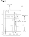
- a ventilation apparatus for an engine according to a second embodiment of the present invention will hereafter be described with reference to Fig. 2 .
- Fig. 2 schematically shows the configuration of an engine 101 employing the ventilation apparatus for an engine of the second embodiment.
- the second embodiment is different from the first embodiment in that an oil return passage 107 does not return oil from a cam chamber into an oil pan 105.
- the second embodiment has a communicating portion 171 allowing communication between the interior of a chain case 106 and a recirculation passage 108.
- components of the second embodiment that are like or the same as corresponding components of the first embodiment are given reference numerals determined by adding 100 to corresponding reference numerals. Description of these components is omitted herein.
- the recirculation passage 108 which is a component of the ventilation apparatus, extends in a cylinder block 102 and a cylinder head 103.
- the recirculation passage 108 extends in a vertical direction.
- the communicating portion 171 is formed in the cylinder block 102 and allows communication between the interior of the chain case 106 and the recirculation passage 108.
- the cross-sectional area of the communicating portion 171 is smaller than the cross-sectional area of the recirculation passage 108.
- An oil jet mechanism for supplying oil to a chain is located in the chain case 106. After being supplied to the chain by the oil jet mechanism, the oil is splashed by the chain and then introduced into an opening of the communicating portion 171.
- the oil return passage 107 includes the communicating portion 171 and the portion of the recirculation passage 108 extending from the portion at which the recirculation passage 108 is connected to the communicating portion 171 to the end of the recirculation passage 108 at the side of the oil pan 105.
- the portion of the recirculation passage 108 from the portion at which the recirculation passage 108 is connected to the communicating portion 171 to the end of the recirculation passage 108 at the side of the oil pan 105 is a common portion 109. That is, the oil return passage 107 is formed by the communicating portion 171 and the common portion 109.
- the space formed in the common portion 109 is the space in which the oil in the oil return passage 107 falls under its own weight.
- the blow-by gas When rising in the recirculation passage 108 toward the intake passage, the blow-by gas strikes oil droplets each falling under their own weight in the common portion 109, which is located in the recirculation passage 108 (the portion extending from the end of the recirculation passage 108 at the side of the oil pan 105 to the communicating portion 171).
- the oil mist contained in the blow-by gas is thus adsorbed by the oil droplets.
- the intermolecular force acting to maintain each oil droplet is greater than the pressure caused by the striking oil mist. As a result, such striking does not cause bubbling.
- the ventilation apparatus for an engine of the second embodiment which has been described, has the advantages (3), (4), and (5), as will be described below, in addition to the advantage (1) of the first embodiment.
- the ventilation apparatus for an engine according to the present invention is not restricted to the configurations of the illustrated embodiments but may be embodied in any suitable modified forms including, for example, the forms described below.
- the common portion 9 is formed inside the cylinder block 2 (see Fig. 1 ). However, since negative pressure is applied from the intake passage into the recirculation passage 8, the oil sent from the oil return passage 7 is likely to be drawn into the intake passage through the common portion 9 and the recirculation passage 8 unless the volume of the common portion 9 is sufficiently large. If the common portion 9 is formed inside the cylinder block 2, the limited space in the cylinder block 2 possibly does not allow the common portion 9 to have a sufficient volume. In this case, as illustrated in Fig. 3 , a common portion 209 may be arranged outside a cylinder head 203 and a cylinder block 202.
- an upstream pipe 281 and a downstream pipe 282, which configure a recirculation passage 208, are arranged outside the cylinder block 202 and the cylinder head 203.
- a case 291 which has a cross-sectional area greater than the cross-sectional area of each of the pipes 281, 282, is arranged between and connected to the upstream pipe 281 and the downstream pipe 282.
- An upstream pipe 271 and a downstream pipe 272, which configure an oil return passage 207, are formed outside the cylinder block 202 and the cylinder head 203.
- the case 291 is arranged between and connected to the upstream pipe 271 and the downstream pipe 272.
- the cross-sectional area of the case 291 is greater than the cross-sectional area of each of the upstream and downstream pipes 271 and 272.
- the interior of the case 291 is a common portion 209, which is the space in which oil falls under its own weight. This configuration allows appropriate setting of the volume of the common portion 209 such that the aforementioned oil drawing is reliably avoided.
- the common portion 109 is the portion of the recirculation passage 108 extending from the portion at which the recirculation passage 108 is connected to the communicating portion 171 to the end of the recirculation passage 108 at the side of the oil pan 105.
- the present invention is not restricted to this configuration.
- the oil return passage and the recirculation passage may cross each other to form a cross as in the first embodiment and its modification.
- the angle at which the oil return passage and the recirculation passage cross each other is not restricted to 90 degrees but may be changed to any other suitable value as needed.
- the cross-sectional area of the communicating portion 171 is smaller than the cross-sectional area of the recirculation passage 108.
- Such sizing is desirable for maintaining the interior of the communicating portion 171 in a state sealed by oil and thus making it unlikely that blow-by gas leaks into the interior of the chain case 106 through the communicating portion 171.
- the cross-sectional area of the communicating portion may be greater than or equal to the cross-sectional area of the recirculation passage.
- the oil return passage returns oil to the oil pan after the oil has been used to lubricate components of the engine.
- the oil may be returned before being used to lubricate the components of the engine.
Landscapes
- Engineering & Computer Science (AREA)
- Mechanical Engineering (AREA)
- General Engineering & Computer Science (AREA)
- Lubrication Details And Ventilation Of Internal Combustion Engines (AREA)
- Lubrication Of Internal Combustion Engines (AREA)
Applications Claiming Priority (1)
| Application Number | Priority Date | Filing Date | Title |
|---|---|---|---|
| PCT/JP2011/070242 WO2013035154A1 (ja) | 2011-09-06 | 2011-09-06 | エンジンの換気装置 |
Publications (3)
| Publication Number | Publication Date |
|---|---|
| EP2754864A1 true EP2754864A1 (de) | 2014-07-16 |
| EP2754864A4 EP2754864A4 (de) | 2015-02-18 |
| EP2754864B1 EP2754864B1 (de) | 2017-04-05 |
Family
ID=47831641
Family Applications (1)
| Application Number | Title | Priority Date | Filing Date |
|---|---|---|---|
| EP11871939.2A Not-in-force EP2754864B1 (de) | 2011-09-06 | 2011-09-06 | Motorbelüftungsvorrichtung |
Country Status (5)
| Country | Link |
|---|---|
| US (1) | US9085998B2 (de) |
| EP (1) | EP2754864B1 (de) |
| JP (1) | JP5787115B2 (de) |
| CN (1) | CN103782000B (de) |
| WO (1) | WO2013035154A1 (de) |
Cited By (2)
| Publication number | Priority date | Publication date | Assignee | Title |
|---|---|---|---|---|
| EP2788596B1 (de) * | 2011-12-09 | 2019-05-01 | Volkswagen Aktiengesellschaft | Brennkraftmaschine und verfahren zum betrieb einer brennkraftmaschine |
| DE102015217372B4 (de) * | 2014-09-12 | 2020-02-20 | Suzuki Motor Corporation | Ölabscheidestruktur für verbrennungsmotoren |
Families Citing this family (5)
| Publication number | Priority date | Publication date | Assignee | Title |
|---|---|---|---|---|
| JP6329802B2 (ja) * | 2014-03-31 | 2018-05-23 | ダイハツ工業株式会社 | 内燃機関 |
| JP6331923B2 (ja) * | 2014-09-24 | 2018-05-30 | スズキ株式会社 | 内燃機関のオイル分離構造 |
| CN104389691A (zh) * | 2014-10-15 | 2015-03-04 | 力帆实业(集团)股份有限公司 | 发动机曲轴箱体油气分离结构 |
| CN106382142B (zh) * | 2016-10-21 | 2019-04-30 | 东风商用车有限公司 | 一种发动机局部机油防乳化系统及其使用方法 |
| DE102019200978B4 (de) * | 2019-01-25 | 2020-11-12 | Vitesco Technologies GmbH | Verfahren und Vorrichtung zur Überprüfung der Funktionsfähigkeit eines Kurbelgehäuseentlüftungssystems eines Verbrennungsmotors |
Family Cites Families (21)
| Publication number | Priority date | Publication date | Assignee | Title |
|---|---|---|---|---|
| JPS57172109U (de) * | 1981-04-27 | 1982-10-29 | ||
| JPS58143109A (ja) * | 1982-02-18 | 1983-08-25 | Yamaha Motor Co Ltd | 車輛用オ−バヘツドカム形エンジンの通路構造 |
| JPS5996469A (ja) | 1982-11-24 | 1984-06-02 | Honda Motor Co Ltd | 内燃機関のブロ−バイガス取出装置 |
| JPS6249607A (ja) | 1985-08-29 | 1987-03-04 | Tohoku Metal Ind Ltd | 巻線装置 |
| JPS6249607U (de) * | 1985-09-13 | 1987-03-27 | ||
| JPH0676533B2 (ja) | 1986-11-20 | 1994-09-28 | 三菱化成株式会社 | 油中水型水溶性共重合体エマルジヨンおよびその製造方法 |
| JPS6390035U (de) * | 1986-12-02 | 1988-06-11 | ||
| US4769050A (en) | 1987-05-20 | 1988-09-06 | Arvin Industries, Inc. | Liquid separator assembly |
| JPH0240908U (de) * | 1988-09-09 | 1990-03-20 | ||
| JPH0539709A (ja) | 1991-08-02 | 1993-02-19 | Kubota Corp | エンジンのブリーザ装置 |
| JP3741159B2 (ja) * | 1995-08-11 | 2006-02-01 | 三菱自動車工業株式会社 | 内燃機関の潤滑油戻し通路 |
| US6167849B1 (en) * | 1998-06-24 | 2001-01-02 | Robert L. Wilson | Crankcase breather oil collector for motorcycles |
| JP3640348B2 (ja) * | 2001-05-17 | 2005-04-20 | 本田技研工業株式会社 | シリンダヘッド構造 |
| DE10203274A1 (de) * | 2002-01-29 | 2003-08-07 | Bosch Gmbh Robert | Ölabscheidevorrichtung |
| KR100551288B1 (ko) * | 2003-11-04 | 2006-02-10 | 현대자동차주식회사 | 블로바이 가스 및 오일 드레인 통로가 형성된 크랭크 케이스 |
| JP4581829B2 (ja) * | 2005-05-10 | 2010-11-17 | トヨタ自動車株式会社 | オイルセパレータ及びブローバイガス還元装置 |
| US7383829B2 (en) * | 2006-02-09 | 2008-06-10 | Toyota Motor Engineering & Manufacturing North America, Inc. | Oil drain device for an engine oil separator |
| JP4162020B2 (ja) * | 2006-07-18 | 2008-10-08 | トヨタ自動車株式会社 | ブローバイガス還元装置のオイル回収構造 |
| JP2008121478A (ja) | 2006-11-10 | 2008-05-29 | Mahle Filter Systems Japan Corp | 内燃機関のブローバイ流路構造 |
| EP2143898A1 (de) * | 2008-07-09 | 2010-01-13 | Ford Global Technologies, LLC | Anordnung mit Zylinderkopf und Zylinderblock |
| JP5282774B2 (ja) * | 2010-10-21 | 2013-09-04 | トヨタ自動車株式会社 | Pcvバルブの取付構造 |
-
2011
- 2011-09-06 CN CN201180073247.0A patent/CN103782000B/zh not_active Expired - Fee Related
- 2011-09-06 WO PCT/JP2011/070242 patent/WO2013035154A1/ja not_active Ceased
- 2011-09-06 EP EP11871939.2A patent/EP2754864B1/de not_active Not-in-force
- 2011-09-06 JP JP2013532341A patent/JP5787115B2/ja not_active Expired - Fee Related
- 2011-09-06 US US14/342,687 patent/US9085998B2/en not_active Expired - Fee Related
Cited By (2)
| Publication number | Priority date | Publication date | Assignee | Title |
|---|---|---|---|---|
| EP2788596B1 (de) * | 2011-12-09 | 2019-05-01 | Volkswagen Aktiengesellschaft | Brennkraftmaschine und verfahren zum betrieb einer brennkraftmaschine |
| DE102015217372B4 (de) * | 2014-09-12 | 2020-02-20 | Suzuki Motor Corporation | Ölabscheidestruktur für verbrennungsmotoren |
Also Published As
| Publication number | Publication date |
|---|---|
| WO2013035154A1 (ja) | 2013-03-14 |
| JPWO2013035154A1 (ja) | 2015-03-23 |
| CN103782000A (zh) | 2014-05-07 |
| CN103782000B (zh) | 2017-05-17 |
| US20140202438A1 (en) | 2014-07-24 |
| EP2754864A4 (de) | 2015-02-18 |
| JP5787115B2 (ja) | 2015-09-30 |
| EP2754864B1 (de) | 2017-04-05 |
| US9085998B2 (en) | 2015-07-21 |
Similar Documents
| Publication | Publication Date | Title |
|---|---|---|
| US9085998B2 (en) | Engine ventilation apparatus | |
| US10533470B2 (en) | Oil separation device for internal combustion engine | |
| US8408190B2 (en) | Air-oil separator for extracting oil from engine blowby gas | |
| CN102076933B (zh) | 内燃发动机油箱装置 | |
| US10221732B2 (en) | Lubrication system for internal combustion engine | |
| WO2023286453A1 (ja) | ガスエンジンシステム | |
| JP2010121537A (ja) | Pcvバルブユニットの取り付け構造 | |
| CN204060856U (zh) | 曲轴箱强制通风系统 | |
| US10107159B2 (en) | Internal combustion engine | |
| JP5906758B2 (ja) | ブローバイガス処理装置のオイルセパレータ | |
| US9057295B2 (en) | Positive crankcase ventilation system | |
| US6725850B2 (en) | Gas-liquid separation device in a vibrator engine | |
| US8905010B2 (en) | Positive crankcase ventilation system for a two-cylinder engine | |
| JP2007064155A (ja) | オイルミスト処理装置 | |
| JP2007009746A (ja) | オイルミスト処理装置 | |
| JP2010163895A (ja) | 内燃機関の吸気制御装置 | |
| US20200018199A1 (en) | Oil supply device | |
| JP2007309214A (ja) | 内燃機関 | |
| US9347345B2 (en) | Internal combustion engines and oil containment systems thereof | |
| JP4549871B2 (ja) | ドライサンプ式潤滑装置を備える内燃機関 | |
| JP2019100313A (ja) | 車両用オイル供給装置 | |
| JP2009013813A (ja) | 内燃機関の潤滑装置 | |
| JP2009250077A (ja) | エンジンの排気ガス再循環装置 | |
| KR101534719B1 (ko) | 차량 엔진의 실린더 헤드 커버 | |
| CN104895644A (zh) | 交通机械内部分流装置 |
Legal Events
| Date | Code | Title | Description |
|---|---|---|---|
| PUAI | Public reference made under article 153(3) epc to a published international application that has entered the european phase |
Free format text: ORIGINAL CODE: 0009012 |
|
| 17P | Request for examination filed |
Effective date: 20140312 |
|
| AK | Designated contracting states |
Kind code of ref document: A1 Designated state(s): AL AT BE BG CH CY CZ DE DK EE ES FI FR GB GR HR HU IE IS IT LI LT LU LV MC MK MT NL NO PL PT RO RS SE SI SK SM TR |
|
| DAX | Request for extension of the european patent (deleted) | ||
| A4 | Supplementary search report drawn up and despatched |
Effective date: 20150119 |
|
| RIC1 | Information provided on ipc code assigned before grant |
Ipc: F01M 13/04 20060101AFI20150113BHEP Ipc: F01M 1/06 20060101ALI20150113BHEP |
|
| 17Q | First examination report despatched |
Effective date: 20160302 |
|
| GRAP | Despatch of communication of intention to grant a patent |
Free format text: ORIGINAL CODE: EPIDOSNIGR1 |
|
| STAA | Information on the status of an ep patent application or granted ep patent |
Free format text: STATUS: GRANT OF PATENT IS INTENDED |
|
| INTG | Intention to grant announced |
Effective date: 20170112 |
|
| GRAS | Grant fee paid |
Free format text: ORIGINAL CODE: EPIDOSNIGR3 |
|
| GRAA | (expected) grant |
Free format text: ORIGINAL CODE: 0009210 |
|
| STAA | Information on the status of an ep patent application or granted ep patent |
Free format text: STATUS: THE PATENT HAS BEEN GRANTED |
|
| AK | Designated contracting states |
Kind code of ref document: B1 Designated state(s): AL AT BE BG CH CY CZ DE DK EE ES FI FR GB GR HR HU IE IS IT LI LT LU LV MC MK MT NL NO PL PT RO RS SE SI SK SM TR |
|
| REG | Reference to a national code |
Ref country code: GB Ref legal event code: FG4D |
|
| REG | Reference to a national code |
Ref country code: CH Ref legal event code: EP |
|
| REG | Reference to a national code |
Ref country code: AT Ref legal event code: REF Ref document number: 882053 Country of ref document: AT Kind code of ref document: T Effective date: 20170415 |
|
| REG | Reference to a national code |
Ref country code: IE Ref legal event code: FG4D |
|
| REG | Reference to a national code |
Ref country code: DE Ref legal event code: R096 Ref document number: 602011036786 Country of ref document: DE |
|
| REG | Reference to a national code |
Ref country code: DE Ref legal event code: R084 Ref document number: 602011036786 Country of ref document: DE |
|
| REG | Reference to a national code |
Ref country code: NL Ref legal event code: MP Effective date: 20170405 |
|
| REG | Reference to a national code |
Ref country code: LT Ref legal event code: MG4D |
|
| REG | Reference to a national code |
Ref country code: AT Ref legal event code: MK05 Ref document number: 882053 Country of ref document: AT Kind code of ref document: T Effective date: 20170405 |
|
| PG25 | Lapsed in a contracting state [announced via postgrant information from national office to epo] |
Ref country code: NL Free format text: LAPSE BECAUSE OF FAILURE TO SUBMIT A TRANSLATION OF THE DESCRIPTION OR TO PAY THE FEE WITHIN THE PRESCRIBED TIME-LIMIT Effective date: 20170405 |
|
| PG25 | Lapsed in a contracting state [announced via postgrant information from national office to epo] |
Ref country code: FI Free format text: LAPSE BECAUSE OF FAILURE TO SUBMIT A TRANSLATION OF THE DESCRIPTION OR TO PAY THE FEE WITHIN THE PRESCRIBED TIME-LIMIT Effective date: 20170405 Ref country code: NO Free format text: LAPSE BECAUSE OF FAILURE TO SUBMIT A TRANSLATION OF THE DESCRIPTION OR TO PAY THE FEE WITHIN THE PRESCRIBED TIME-LIMIT Effective date: 20170705 Ref country code: GR Free format text: LAPSE BECAUSE OF FAILURE TO SUBMIT A TRANSLATION OF THE DESCRIPTION OR TO PAY THE FEE WITHIN THE PRESCRIBED TIME-LIMIT Effective date: 20170706 Ref country code: HR Free format text: LAPSE BECAUSE OF FAILURE TO SUBMIT A TRANSLATION OF THE DESCRIPTION OR TO PAY THE FEE WITHIN THE PRESCRIBED TIME-LIMIT Effective date: 20170405 Ref country code: ES Free format text: LAPSE BECAUSE OF FAILURE TO SUBMIT A TRANSLATION OF THE DESCRIPTION OR TO PAY THE FEE WITHIN THE PRESCRIBED TIME-LIMIT Effective date: 20170405 Ref country code: LT Free format text: LAPSE BECAUSE OF FAILURE TO SUBMIT A TRANSLATION OF THE DESCRIPTION OR TO PAY THE FEE WITHIN THE PRESCRIBED TIME-LIMIT Effective date: 20170405 Ref country code: AT Free format text: LAPSE BECAUSE OF FAILURE TO SUBMIT A TRANSLATION OF THE DESCRIPTION OR TO PAY THE FEE WITHIN THE PRESCRIBED TIME-LIMIT Effective date: 20170405 |
|
| PG25 | Lapsed in a contracting state [announced via postgrant information from national office to epo] |
Ref country code: LV Free format text: LAPSE BECAUSE OF FAILURE TO SUBMIT A TRANSLATION OF THE DESCRIPTION OR TO PAY THE FEE WITHIN THE PRESCRIBED TIME-LIMIT Effective date: 20170405 Ref country code: SE Free format text: LAPSE BECAUSE OF FAILURE TO SUBMIT A TRANSLATION OF THE DESCRIPTION OR TO PAY THE FEE WITHIN THE PRESCRIBED TIME-LIMIT Effective date: 20170405 Ref country code: IS Free format text: LAPSE BECAUSE OF FAILURE TO SUBMIT A TRANSLATION OF THE DESCRIPTION OR TO PAY THE FEE WITHIN THE PRESCRIBED TIME-LIMIT Effective date: 20170805 Ref country code: BG Free format text: LAPSE BECAUSE OF FAILURE TO SUBMIT A TRANSLATION OF THE DESCRIPTION OR TO PAY THE FEE WITHIN THE PRESCRIBED TIME-LIMIT Effective date: 20170705 Ref country code: PL Free format text: LAPSE BECAUSE OF FAILURE TO SUBMIT A TRANSLATION OF THE DESCRIPTION OR TO PAY THE FEE WITHIN THE PRESCRIBED TIME-LIMIT Effective date: 20170405 Ref country code: RS Free format text: LAPSE BECAUSE OF FAILURE TO SUBMIT A TRANSLATION OF THE DESCRIPTION OR TO PAY THE FEE WITHIN THE PRESCRIBED TIME-LIMIT Effective date: 20170405 |
|
| REG | Reference to a national code |
Ref country code: DE Ref legal event code: R097 Ref document number: 602011036786 Country of ref document: DE |
|
| PG25 | Lapsed in a contracting state [announced via postgrant information from national office to epo] |
Ref country code: EE Free format text: LAPSE BECAUSE OF FAILURE TO SUBMIT A TRANSLATION OF THE DESCRIPTION OR TO PAY THE FEE WITHIN THE PRESCRIBED TIME-LIMIT Effective date: 20170405 Ref country code: RO Free format text: LAPSE BECAUSE OF FAILURE TO SUBMIT A TRANSLATION OF THE DESCRIPTION OR TO PAY THE FEE WITHIN THE PRESCRIBED TIME-LIMIT Effective date: 20170405 Ref country code: DK Free format text: LAPSE BECAUSE OF FAILURE TO SUBMIT A TRANSLATION OF THE DESCRIPTION OR TO PAY THE FEE WITHIN THE PRESCRIBED TIME-LIMIT Effective date: 20170405 Ref country code: SK Free format text: LAPSE BECAUSE OF FAILURE TO SUBMIT A TRANSLATION OF THE DESCRIPTION OR TO PAY THE FEE WITHIN THE PRESCRIBED TIME-LIMIT Effective date: 20170405 Ref country code: CZ Free format text: LAPSE BECAUSE OF FAILURE TO SUBMIT A TRANSLATION OF THE DESCRIPTION OR TO PAY THE FEE WITHIN THE PRESCRIBED TIME-LIMIT Effective date: 20170405 |
|
| PLBE | No opposition filed within time limit |
Free format text: ORIGINAL CODE: 0009261 |
|
| STAA | Information on the status of an ep patent application or granted ep patent |
Free format text: STATUS: NO OPPOSITION FILED WITHIN TIME LIMIT |
|
| PG25 | Lapsed in a contracting state [announced via postgrant information from national office to epo] |
Ref country code: SM Free format text: LAPSE BECAUSE OF FAILURE TO SUBMIT A TRANSLATION OF THE DESCRIPTION OR TO PAY THE FEE WITHIN THE PRESCRIBED TIME-LIMIT Effective date: 20170405 Ref country code: IT Free format text: LAPSE BECAUSE OF FAILURE TO SUBMIT A TRANSLATION OF THE DESCRIPTION OR TO PAY THE FEE WITHIN THE PRESCRIBED TIME-LIMIT Effective date: 20170405 |
|
| 26N | No opposition filed |
Effective date: 20180108 |
|
| REG | Reference to a national code |
Ref country code: CH Ref legal event code: PL |
|
| GBPC | Gb: european patent ceased through non-payment of renewal fee |
Effective date: 20170906 |
|
| PG25 | Lapsed in a contracting state [announced via postgrant information from national office to epo] |
Ref country code: MC Free format text: LAPSE BECAUSE OF FAILURE TO SUBMIT A TRANSLATION OF THE DESCRIPTION OR TO PAY THE FEE WITHIN THE PRESCRIBED TIME-LIMIT Effective date: 20170405 Ref country code: SI Free format text: LAPSE BECAUSE OF FAILURE TO SUBMIT A TRANSLATION OF THE DESCRIPTION OR TO PAY THE FEE WITHIN THE PRESCRIBED TIME-LIMIT Effective date: 20170405 |
|
| REG | Reference to a national code |
Ref country code: IE Ref legal event code: MM4A |
|
| REG | Reference to a national code |
Ref country code: BE Ref legal event code: MM Effective date: 20170930 |
|
| PG25 | Lapsed in a contracting state [announced via postgrant information from national office to epo] |
Ref country code: LU Free format text: LAPSE BECAUSE OF NON-PAYMENT OF DUE FEES Effective date: 20170906 |
|
| REG | Reference to a national code |
Ref country code: FR Ref legal event code: ST Effective date: 20180531 |
|
| PG25 | Lapsed in a contracting state [announced via postgrant information from national office to epo] |
Ref country code: GB Free format text: LAPSE BECAUSE OF NON-PAYMENT OF DUE FEES Effective date: 20170906 Ref country code: LI Free format text: LAPSE BECAUSE OF NON-PAYMENT OF DUE FEES Effective date: 20170930 Ref country code: IE Free format text: LAPSE BECAUSE OF NON-PAYMENT OF DUE FEES Effective date: 20170906 Ref country code: CH Free format text: LAPSE BECAUSE OF NON-PAYMENT OF DUE FEES Effective date: 20170930 |
|
| PG25 | Lapsed in a contracting state [announced via postgrant information from national office to epo] |
Ref country code: BE Free format text: LAPSE BECAUSE OF NON-PAYMENT OF DUE FEES Effective date: 20170930 Ref country code: FR Free format text: LAPSE BECAUSE OF NON-PAYMENT OF DUE FEES Effective date: 20171002 |
|
| PG25 | Lapsed in a contracting state [announced via postgrant information from national office to epo] |
Ref country code: MT Free format text: LAPSE BECAUSE OF NON-PAYMENT OF DUE FEES Effective date: 20170906 |
|
| PG25 | Lapsed in a contracting state [announced via postgrant information from national office to epo] |
Ref country code: HU Free format text: LAPSE BECAUSE OF FAILURE TO SUBMIT A TRANSLATION OF THE DESCRIPTION OR TO PAY THE FEE WITHIN THE PRESCRIBED TIME-LIMIT; INVALID AB INITIO Effective date: 20110906 |
|
| PG25 | Lapsed in a contracting state [announced via postgrant information from national office to epo] |
Ref country code: CY Free format text: LAPSE BECAUSE OF NON-PAYMENT OF DUE FEES Effective date: 20170405 |
|
| PG25 | Lapsed in a contracting state [announced via postgrant information from national office to epo] |
Ref country code: MK Free format text: LAPSE BECAUSE OF FAILURE TO SUBMIT A TRANSLATION OF THE DESCRIPTION OR TO PAY THE FEE WITHIN THE PRESCRIBED TIME-LIMIT Effective date: 20170405 |
|
| PG25 | Lapsed in a contracting state [announced via postgrant information from national office to epo] |
Ref country code: TR Free format text: LAPSE BECAUSE OF FAILURE TO SUBMIT A TRANSLATION OF THE DESCRIPTION OR TO PAY THE FEE WITHIN THE PRESCRIBED TIME-LIMIT Effective date: 20170405 |
|
| PG25 | Lapsed in a contracting state [announced via postgrant information from national office to epo] |
Ref country code: PT Free format text: LAPSE BECAUSE OF FAILURE TO SUBMIT A TRANSLATION OF THE DESCRIPTION OR TO PAY THE FEE WITHIN THE PRESCRIBED TIME-LIMIT Effective date: 20170405 |
|
| PG25 | Lapsed in a contracting state [announced via postgrant information from national office to epo] |
Ref country code: AL Free format text: LAPSE BECAUSE OF FAILURE TO SUBMIT A TRANSLATION OF THE DESCRIPTION OR TO PAY THE FEE WITHIN THE PRESCRIBED TIME-LIMIT Effective date: 20170405 |
|
| PGFP | Annual fee paid to national office [announced via postgrant information from national office to epo] |
Ref country code: DE Payment date: 20210727 Year of fee payment: 11 |
|
| REG | Reference to a national code |
Ref country code: DE Ref legal event code: R119 Ref document number: 602011036786 Country of ref document: DE |
|
| PG25 | Lapsed in a contracting state [announced via postgrant information from national office to epo] |
Ref country code: DE Free format text: LAPSE BECAUSE OF NON-PAYMENT OF DUE FEES Effective date: 20230401 |