EP2756875A1 - Luftreiniger zur Entfernung von Luftverunreinigern aus einem Luftstrom - Google Patents
Luftreiniger zur Entfernung von Luftverunreinigern aus einem Luftstrom Download PDFInfo
- Publication number
- EP2756875A1 EP2756875A1 EP14164577.0A EP14164577A EP2756875A1 EP 2756875 A1 EP2756875 A1 EP 2756875A1 EP 14164577 A EP14164577 A EP 14164577A EP 2756875 A1 EP2756875 A1 EP 2756875A1
- Authority
- EP
- European Patent Office
- Prior art keywords
- filter
- elements
- spiral
- filter elements
- air cleaner
- Prior art date
- Legal status (The legal status is an assumption and is not a legal conclusion. Google has not performed a legal analysis and makes no representation as to the accuracy of the status listed.)
- Granted
Links
Images




Classifications
-
- B—PERFORMING OPERATIONS; TRANSPORTING
- B01—PHYSICAL OR CHEMICAL PROCESSES OR APPARATUS IN GENERAL
- B01D—SEPARATION
- B01D46/00—Filters or filtering processes specially modified for separating dispersed particles from gases or vapours
- B01D46/24—Particle separators, e.g. dust precipitators, using rigid hollow filter bodies
-
- A—HUMAN NECESSITIES
- A63—SPORTS; GAMES; AMUSEMENTS
- A63F—CARD, BOARD, OR ROULETTE GAMES; INDOOR GAMES USING SMALL MOVING PLAYING BODIES; VIDEO GAMES; GAMES NOT OTHERWISE PROVIDED FOR
- A63F13/00—Video games, i.e. games using an electronically generated display having two or more dimensions
- A63F13/25—Output arrangements for video game devices
-
- A—HUMAN NECESSITIES
- A61—MEDICAL OR VETERINARY SCIENCE; HYGIENE
- A61L—METHODS OR APPARATUS FOR STERILISING MATERIALS OR OBJECTS IN GENERAL; DISINFECTION, STERILISATION OR DEODORISATION OF AIR; CHEMICAL ASPECTS OF BANDAGES, DRESSINGS, ABSORBENT PADS OR SURGICAL ARTICLES; MATERIALS FOR BANDAGES, DRESSINGS, ABSORBENT PADS OR SURGICAL ARTICLES
- A61L9/00—Disinfection, sterilisation or deodorisation of air
- A61L9/01—Deodorant compositions
- A61L9/014—Deodorant compositions containing sorbent material, e.g. activated carbon
-
- A—HUMAN NECESSITIES
- A63—SPORTS; GAMES; AMUSEMENTS
- A63F—CARD, BOARD, OR ROULETTE GAMES; INDOOR GAMES USING SMALL MOVING PLAYING BODIES; VIDEO GAMES; GAMES NOT OTHERWISE PROVIDED FOR
- A63F13/00—Video games, i.e. games using an electronically generated display having two or more dimensions
- A63F13/80—Special adaptations for executing a specific game genre or game mode
-
- A—HUMAN NECESSITIES
- A63—SPORTS; GAMES; AMUSEMENTS
- A63F—CARD, BOARD, OR ROULETTE GAMES; INDOOR GAMES USING SMALL MOVING PLAYING BODIES; VIDEO GAMES; GAMES NOT OTHERWISE PROVIDED FOR
- A63F3/00—Board games; Raffle games
- A63F3/06—Lottos or bingo games; Systems, apparatus or devices for checking such games
-
- A—HUMAN NECESSITIES
- A63—SPORTS; GAMES; AMUSEMENTS
- A63F—CARD, BOARD, OR ROULETTE GAMES; INDOOR GAMES USING SMALL MOVING PLAYING BODIES; VIDEO GAMES; GAMES NOT OTHERWISE PROVIDED FOR
- A63F5/00—Roulette games
-
- A—HUMAN NECESSITIES
- A63—SPORTS; GAMES; AMUSEMENTS
- A63F—CARD, BOARD, OR ROULETTE GAMES; INDOOR GAMES USING SMALL MOVING PLAYING BODIES; VIDEO GAMES; GAMES NOT OTHERWISE PROVIDED FOR
- A63F9/00—Games not otherwise provided for
- A63F9/24—Games using electronic circuits not otherwise provided for
-
- B—PERFORMING OPERATIONS; TRANSPORTING
- B01—PHYSICAL OR CHEMICAL PROCESSES OR APPARATUS IN GENERAL
- B01D—SEPARATION
- B01D45/00—Separating dispersed particles from gases or vapours by gravity, inertia, or centrifugal forces
- B01D45/04—Separating dispersed particles from gases or vapours by gravity, inertia, or centrifugal forces by utilising inertia
- B01D45/08—Separating dispersed particles from gases or vapours by gravity, inertia, or centrifugal forces by utilising inertia by impingement against baffle separators
- B01D45/10—Separating dispersed particles from gases or vapours by gravity, inertia, or centrifugal forces by utilising inertia by impingement against baffle separators which are wetted
-
- B—PERFORMING OPERATIONS; TRANSPORTING
- B01—PHYSICAL OR CHEMICAL PROCESSES OR APPARATUS IN GENERAL
- B01D—SEPARATION
- B01D46/00—Filters or filtering processes specially modified for separating dispersed particles from gases or vapours
- B01D46/0002—Casings; Housings; Frame constructions
-
- B—PERFORMING OPERATIONS; TRANSPORTING
- B01—PHYSICAL OR CHEMICAL PROCESSES OR APPARATUS IN GENERAL
- B01D—SEPARATION
- B01D47/00—Separating dispersed particles from gases, air or vapours by liquid as separating agent
- B01D47/02—Separating dispersed particles from gases, air or vapours by liquid as separating agent by passing the gas or air or vapour over or through a liquid bath
- B01D47/028—Separating dispersed particles from gases, air or vapours by liquid as separating agent by passing the gas or air or vapour over or through a liquid bath by directing the gas through a wetted wire mesh or a perforated plate
-
- B—PERFORMING OPERATIONS; TRANSPORTING
- B01—PHYSICAL OR CHEMICAL PROCESSES OR APPARATUS IN GENERAL
- B01D—SEPARATION
- B01D2279/00—Filters adapted for separating dispersed particles from gases or vapours specially modified for specific uses
- B01D2279/50—Filters adapted for separating dispersed particles from gases or vapours specially modified for specific uses for air conditioning
Definitions
- the present invention relates to an air cleaner for removing air pollutants from an air stream, for instance such as the cleaning exhaust/intake gas of an amusement machine, said air cleaner comprising a filter device including at least one filter layer held by a filter holder in said airflow substantially perpendicular to a main flow direction thereof and including a plurality of preferably stick-shaped filter elements neighboring each other.
- An air cleaner of the above mentioned type is known from WO 2007/028176 A1 disclosing a filter device for removing air polluting materials from machine exhaust.
- This known device is provided with a plurality of filter sticks which are held at the opposite ends in a filter housing and arranged in a plurality of layers one above the other with a lateral offset.
- the said filter sticks are made of a porous material such as plastic foam which is wetted with a fluid such as silicone oil.
- Such wet filters are very effective in removing air polluting materials including ultrafine particles and gaseous pollutants such as unpleasant odors which are chemically absorbed and neutralized by coming into contact with the fluid.
- the array of the filter sticks is enclosed in a filter housing forming a tube-like channel in the cross-section of which the filter sticks are placed.
- This tube-like channel is intended to direct the flow of polluted air through the filter stick array and to prevent the airflow from getting out of the way of the filter sticks.
- filter stick arrangement is disadvantageous in certain aspects, for example it has shown that there is no uniform filter load on all sticks, in particular the filter load onto the inner sticks is different from the filter load onto the outer sticks.
- filter stick arrangement is sensible to airflow velocity.
- EP 1 345 669 Another filter device having wet filter sticks for cleaning the exhaust air of office machines is known from EP 1 345 669 which suggests to hold the filter sticks in upright position at their opposite ends so that the fluid for wetting the elements is caused to flow downward along the filter sticks by gravity.
- the said fluid which is oil is stored in a compartment above the filter sticks, wherein an oil pad may be provided in said compartment.
- EP 0 515 759 A1 discloses an air filter device provided with a cylindrical housing having its front and back faces covered with grilles so that the air to be cleaned can flow through said housing in which the filter body which may comprise carbon pellets is provided.
- the said filter housing is arranged at the back side of the motor of a ventilator directing airflow onto the open front face of said filter housing.
- the present invention aims to improve the aforementioned filter devices and to avoid disadvantages thereof. It is an objective of the present invention to provide an improved air cleaner for removing air pollutants from airflow such as the intake/exhaust air with high efficiency and having a small-sized filter device to allow accommodation thereof in for instance a small interior.
- the filter device has no closed surrounding along the circumference of the filter layers, but provides for an open side along at least a portion of the periphery of the filter layer. At least one circumferential side section of the filter layer parallel to or tangential to the longitudinal axis of an outermost filter element is formed as an open side free of flow control elements surrounding the filter layer.
- the present invention avoids such flow-control-elements for guiding the air stream through the filter layer and/or preventing the airflow from diverging away from the filter layer, wherein in particular the filter layer, at its open side, is dispensed with flow-control-elements such as flow guiding surfaces, flow channel walls, fences or housing walls surrounding the filter layer.
- flow-control-elements such as flow guiding surfaces, flow channel walls, fences or housing walls surrounding the filter layer.
- the filter device shows a very compact, small-sized structure that allows the air cleaner to be received in small spaces such as the interior of amusement machine cabinets.
- the filter elements can be supported to have at least one free end.
- the filter elements are held in said airflow by a filter holder in a cantilevered fashion with at least one end of the filter elements extending free and unsupported. The absence of any support element at the respective end section of the filter elements avoids any disturbances and allows the end sections to catch air pollutants efficiently.
- the said filter holder is attached to a middle section of the filter elements which thus have two free ends.
- a centred support of the filter elements with a single holding element does not only minimize the holding device's cross-section obstructing the airflow, but also reduces the unsupported length of the filter elements which is approximately only half the length of the entire filter elements.
- the holding device may be attached to an end section of the filter elements so that the said filter elements have only one free, unsupported end.
- This classic type of cantilevered support facilitates mounting and replacing the filter layers, in particular when there are a plurality of filter layers one of above the other.
- the holding device includes a substantially bar- or beam-shaped holding element to which all filter elements of a filter layer are rigidly connected.
- the said holding element preferably extends across the width of the filter layer, wherein the holding element's longitudinal axis may extend substantially perpendicular to the longitudinal axis of the filter elements.
- the holding element may extend diagonally across the filter elements so that a longitudinal axis of the holding element is angled to the longitudinal axis of the filter elements at an angle of about 30° to 90°, preferably 30° to 60°.
- the filter elements may be supported at both ends by a pair of holding elements.
- an increased strength against breaking of the filter elements is achieved.
- the end sections of the filter elements are rigidly connected to respective holding elements so that the respective opposite sides of the filter layer are closed by the said holding elements. Nevertheless, the remaining sections of the circumference of the filter layer, that is the circumferential sides parallel to the longitudinal axis of the filter elements, are open with no holding elements or fences or housing walls surrounding the filter layer.
- the holding element may have bore-like recesses corresponding in cross-sectional shape to the filter elements.
- the said at least one holding element which is preferably bar- or beam-shaped includes a support surface into which the filter elements are embedded with a support section, wherein preferably the support sections of the filter elements are embedded only partly in said support surface so that another part of the circumferential side of the filter element protrudes from said support surface. Due to the unembedded portion (i.e.
- a sector of 1 ⁇ 2 ⁇ to 3/2 ⁇ of the circumference of the supported section of the filter elements may be embedded in the support surface of the holding element.
- a sector of 1 ⁇ of the circumference is embedded to allow easy removal of both the filter elements and the holding element from a mould.
- the said holding element may be formed from a material different from the filter elements material, wherein the support surface of the holding element may have contours adapted to the shape of the circumferential side of the filter elements to be embedded so that the filter elements nestle against said contours.
- the support surface of the holding element may have a groove-shaped depression being cylindrically contoured. In order to connect the filter elements to the holding element, they may be glued into the said embedding contours.
- the holding elements may be formed integrally with the filter elements in one part from the same material, wherein preferably a sintering process may be used.
- the filter elements and the holding element may be molded, possibly in a foam molding process.
- the above mentioned cantilevered support structure is preferred since it facilitates removal of the mould halves from the molded filter elements and holding element.
- the one-piece structure comprising the holding element and the filter elements may have a shape without undercuts and counterdrafts in the direction of the longitudinal axis of the filter elements and/or a direction perpendicular thereto.
- the said one-piece structure comprising the filter elements and the holding element may be shaped such that there is a parting plane preferably extending perpendicular to the longitudinal axis of the filter elements.
- all filter elements of a filter layer are formed in one piece with the holding element(s) for holding the filter layer, wherein even the filter elements of more than one filter layer may be formed in one piece with the holding element thereof.
- the filter device is a wet filter device including a suitable fluid for wetting the structural material of the filter elements.
- the filter elements may be designed as storage medium for a chemically and/or physically active fluid, which adsorbs or absorbs air-polluting materials.
- fluids such as oils, emulsions or liquids may be used depending on and adjusted to the type of pollutants which are present in the air to be cleaned.
- antibacterial, antiviral, antimycotic or fungicidal agents may be added to the wetting fluid.
- the base material of the filter element which is wetted may comprise different, preferably porous materials such as plastic foams, organic, inorganic or natural fibres such as cellulose or polyester, wherein it is a preferred embodiment to use filter elements made from PU foam wetted with silicone oil.
- the filter device is given a modular structure consisting of basic components which can be attached to each other in varying numbers and/or varying orientations.
- the holding device for holding the filter elements is designed such that it can be connected with a holding device having the identical shape.
- the holding device is provided with hermaphrodite connecting means for connecting at least two filter holders to each other to create at least two filter layers one above the other. Consequently, a stack of filter layers can be created just by connecting the desired number of holding devices each holding a filter layer including a plurality of filter elements.
- the filter elements are positioned offset to the aforementioned hermaphrodite connecting means in a way that - when two filter holders are connected to each other - the filter elements in a first filter layer overlap the spacings between the filter elements in a second layer when viewed in the direction of the airflow.
- the aforementioned holding element of the holding device is provided with the said hermaphrodite connecting means on a back side opposite to the support surface where the filter elements are embedded. Consequently, two beam-shaped holding elements can be connected to each other with their back sides facing each other.
- the filter elements basically may have different geometries and shapes, wherein it is preferred to have stick-shaped filter elements with a length to diameter ratio of more than 5, in particular more than 10, that means the stick-shaped filter elements may have a length at least five times the diameter of the filter element.
- the cross-sectional shape also may vary and may be adapted to operating conditions.
- the filter elements may have a triangle or a polygonal cross-section, wherein in particular a rectangular or oblong cross-section may be provided.
- the filter elements advantageously have a rounded cross-section, for example a circular, oval or elliptical cross-section to achieve a smooth flow around the filter elements to enhance the absorption of pollutants.
- the filter elements are substantially straight rods which are arranged substantially parallel to each other in a filter layer. If the filter device contains a plurality of filter layers, the filter rods in different layers may be arranged parallel to each other with the filter rods in different layers being offset to each other such that the filter rods in a first layer overlap the spacings between the filter rods in a second layer when viewed in the direction of airflow.
- the filter elements of at least one filter layer may be formed by at least one curved, snake-shaped and/or preferably spiral filter rod having sections parallel to and spaced apart from each other.
- the snake-like filter rod may meander or correspond to a Greek key pattern having substantially straight legs parallel to each other and neighboring each other.
- the snake-like filter rod has a spiral shape, for example the shape of a logarithmic spiral or the shape of a linear spiral. Filter layers including such spiral filter rods provide for a large effective filter surface in comparison to a small surface of the holding device, wherein the large effective filter surface can be achieved despite a rather compact structure and small circumference of the filter layer.
- such a spiral-shaped filter rod is supported in a cantilevered fashion as mentioned before, wherein advantageously the inner end of the spiral filter rod is attached to a holding element of the holding device.
- a plurality of spiral filter rods may be combined with each other, wherein it is preferred to have a first spiral filter rod rotationally offset relative to a second spiral filter rod.
- the rotational offset of the plurality of spiral filter rods is chosen such that a first spiral filter rod overlaps the spacings between the legs of a second spiral filter rod when viewed in the direction of the spiral axis, wherein preferably the said plurality of spiral filter rods have a common spiral axis.
- the said plurality of spiral filter rods can be connected with their inner ends to a common holding element preferably having a cylindrical-shape and extending substantially parallel to the spiral axis.
- two spiral filter rods may be arranged in one common plane or, in the alternative, in two substantially parallel planes spaced apart from each other.
- the later arrangement in parallel planes spaced from each other is preferred in terms of a better interlace pattern or overlap which helps to avoid that the airflow passes the filter layers without contacting the filter elements.
- the air passing through a gap between two filter elements of the first layer straight forwardly flows against a filter element of the second filter layer.
- the spiral filter elements may have shapes identical to each other.
- At least two spiral filter elements may have shapes complementary to each other such that a first spiral filter element exactly fits in the spacing between the legs of the second spiral filter element.
- Such complementary shape allows cutting the filter elements out of a common preferably plate-shaped blank.
- the filter layer(s) of the filter device may be mounted to a basic support structure directly by means of the aforementioned holding elements.
- the filter layer may be mounted to ventilating means for urging the airflow through the filter device, wherein for example the holding element may be attached to the driving unit for driving the ventilator blades or a driving unit support.
- the filter layer of the filter device are inserted in a mounting frame
- said mounting frame including an insertion recess fully overlapping the projected area of the filter layer when viewed in the direction of the airflow, thus enabling insertion and removal of the filter layer into/from the mounting frame in the direction of the airflow.
- such mounting structure significantly facilitates mounting, demounting and replacement of the filter layer, since it is not necessary to thread the filter elements separately into holding recesses as it is the case in the prior art where the filter elements are to be inserted in a direction perpendicular to the airflow and/or parallel to the longitudinal direction of the filter sticks. This is advantageous in particular when the filter elements are supported in a cantilevered fashion so they have free, unsupported ends.
- the insertion recess of the said mounting may have a window opening shape basically corresponding to the shape or circumference of the filter layer to be inserted.
- the insertion recess is defined by a cylindrical through hole through the mounting frame, wherein the inner circumference of the through hole basically corresponds to the outer circumference of the filter layer such that the filter layer is hold in said insertion recess by means of a press fit.
- the insertion recess does not necessarily hold each side or the entire circumference of the filter layer, but may hold the filter at opposite sides only.
- the filter layer consists of an array of parallel, substantially straight filter sticks, it is preferred to have the press fit to the insertion recess at the ends of the said stick-shaped elements, whereas the other two sides of the filter layer parallel to the longitudinal axis of the filter sticks may have some spacing to the surrounding insertion recess. Press fitting the ends of the filter sticks into the insertion recess and/or the holding elements provided at these ends of the filter sticks into the insertion recess, uses the filter sticks as compression bars or columns which are subjected to buckling strain only.
- the air cleaner is preferably provided inside the cabinet of a for instance gambling or amusement machine so that the air is filtered inside the housing of the machine.
- Amusement machines such as coin operated gambling machines are usually operated in casinos or gambling halls where the air is often polluted due to smoking, human transpiration or the smell of food. Another issue are the exhaust gases created by the amusement machines which are usually provided with electronic controllers and displays producing hot exhaust air often polluted with dust or other particles. Therefore, it would be desirable to clean the air in the rooms where such amusement machines are used, wherein it would be desirable to have the intake air of the machines cleaned to avoid harm to the sensitive components of the amusement machines and, on the other hand, to clean the exhaust gases of such amusement machines to achieve a better air condition in the room where the machines are operated to improve the sense of comfort of the players using the amusement machines.
- the air cleaner cleans both the intake air and the exhaust air of the amusement machine, thereby improving the quality of the air in the respective room of the casino or gambling hall and thus improving the sense of comfort of the visitors, and on the other hand, protects the electronic components of the amusement machine against the position of pollution particles present in the intake air.
- the air cleaner is preferably used in an amusement machine, there are further options for using the air cleaner.
- the air cleaner can be used for other office machines such as laser printers, for household appliances such as vacuum cleaners.
- FIG 1 shows a filter device 1 comprising a plurality of filter elements 5 which are formed by straight filter rods 13 in this embodiment.
- the said filter elements 6 are arranged in a first filter layer 4a and a second filter layer 4b one above the other, wherein the filter elements 6 basically extend parallel to each other.
- the filter elements in different layers are preferably offset relative to each other so that the filter elements 6 in a first layer 4a overlap with spacings between the filter elements 6 in the second layer 4b.
- both filter layers 4a and 4b may have the same partition between the filter elements, wherein the offset perpendicular to the longitudinal axis of the filter elements corresponds to half the distance between two neighboring filter elements, cf. figures 6 and 7 .
- the spacings between neighboring filter elements 6 in one layer 4 has a width preferably and approximately corresponding to the diameter of a filter element 6, cf. figure 7 . Consequently, if the two layers 4a and 4b would be positioned in one common plane, the filter elements 6 would touch each other and form a closed panel.
- the diameters and/or the partition between the filter elements may vary and thus other geometrical structures are possible.
- the distance between the filter elements 6 in the different filter layers 4a and 4b also may be in the range of the diameter of the filter rods, wherein it is an advantageous embodiment that the distance between the upper side of the first layer to the lower side of the upper layer, when measured in the direction of airflow, is slightly smaller than the diameter of the filter elements.
- different filter elements may have different diameters, it is preferred to have the same diameter for all filter elements.
- the filter elements can have a cylindrical shape with circular cross-section.
- the filter elements 6 of a filter layer 4a are held in position by a filter holder 5 comprising at least one holding element 9 which is preferably bar- or beam-shaped as shown in the figures. More particularly, a holding element 9 may be used which has a support surface 10 into which the filter elements 6 are embedded with the circumferential sides of their support section 6d.
- the support surface 10 of the holding element 9 may have contours adapted to the circumferential contour of the filter elements 6.
- the said support surface may have groove-shaped depressions in which the support sections 6d of the filter elements 6 are nestled or embedded so that there is a two-dimensional contact between the filter elements 6 and the holding element 9.
- the said depressions in the support surface 10 of the holding element 9 may be formed as cylindrical support grooves 18.
- the filter elements 6 are embedded in the support surface 10 of the holding element 9 only in part so that a partial sector of the circumferential surface of the filter elements 6 is embedded in the holding element 6, whereas the remaining sector of the circumferential surface of the filter elements is not embedded and/or may protrude above the said support surface 10.
- the filter elements 6 are embedded in the holding element 9 with half of their diameters. In other words, a sector of 1/2 ⁇ is embedded, cf. figure 3 .
- the back surface of the holding element 9 opposite to the embedded filter elements 6 forms a substantially flat mounting surface 11 which allows two holding elements 9 to be connected with each other back side to back side as it is shown in figures 5-7 .
- a modular filter device 6 is created, wherein multiple filter layer 4 can be positioned one above the other in an easy way.
- the holding element 9 may be provided with hermaphrodite connecting means 12 which allow identically shaped holding elements 9 to be connected with each other.
- the said hermaphrodite connecting means 12 include a connecting pin 32 and a connecting hole 33 positioned at opposite sides of the said support surface 10, wherein the connecting pin 32 and connecting hole 33 are spaced the same distance from the centre of the holding element 9 so that the holding elements 9 can be mounted atop of each other in a congruent fashion.
- the filter elements 6 are offset with respect to the centre of the holding element 9 and/or the centre between the connecting means 12, wherein the offset is perpendicular to the longitudinal axis of the filter elements 6.
- the said offset is such that the filter elements 6 of one layer 4a overlaps with the spacings 17 between the filter elements 6 of the other filter layer 4b, when the two holding elements 9 are connected to each other as shown in figure 6 .
- the latter may be made of an elastic material and/or may have a slight bending as shown in figure 4 so that it is made subject to elastic deformation when connected to another holding element 9.
- the holding elements 9 may be provided with through holes 34 into which connection pins or screws or other engagement means may be inserted as it is shown in figure 7 .
- the said through holes 34 are positioned such that the through holes 34 in different holding elements 9 are aligned with each other when the said different holding elements 9 are put on to each other back side to back side in a congruent fashion.
- two holding elements may be attached to the opposite end sections 6a and 6b of the filter elements 6 so that both ends of the filter elements 6 are supported and held in position.
- the filter elements 6 are supported in a cantilevered fashion so that the filter elements 6 have free, unsupported ends 6a and 6b.
- a single holding element 9 may be attached to the middle section 6c of the filter elements 6 so that the said filter elements 6 have two unsupported free ends 6a and 6b.
- Such a cantilevered support of the filter elements 6 does not only reduce the size of the filter holder 5 and thus increases the effective filter surface of the filter elements 6, but also facilitates the production of filter element 6 and the holding element 9 in a molding process.
- such support structure as shown in figure 9 facilitates the demolding step and removing the mould halves from the filter elements 6 and the holding element 9 even when the filter elements 6 and the holding element 9 are formed integrally with each other in one piece.
- a one-piece structure comprising the holding element 9 and the filter element 6 may have a shape without undercuts and counterdrafts in the direction of the longitudinal axis of the filter elements so that there is a parting plane perpendicular to the longitudinal axis of the filter sticks.
- the molding halves 29 and 30 used for molding/sintering the filter elements 6 and the holding element 9 in one piece may be removed by moving the said halves 29 and 30 away from each other in a direction substantially parallel to the longitudinal axis 25 of the filter elements 6.
- the holding element 9 may be made of the same material as the filter sticks which further facilitates the molding process. However, even if the said integral one-piece structure is provided, the holding element 9 and the filter element 6 may be made of different materials, for example by means of a two-component molding process. This allows the holding element 9 to be made of a more rigid material and/or a strengthened material.
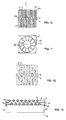
- Figures 10-13 show an embodiment where a plurality of straight filter rods 13 are supported by a common holding bar at a middle section 6c similar to the embodiment of figure 9 . Contrary to the embodiment of figure 9 , the filter elements 6 are embedded in the support surface 10 of two holding elements 9 which are connected to each other back side to back side as explained with reference to figure 7 . As can be seen from figure 13 , two layers 4a and 4b of filter elements 6 are held by two holding elements 9 lying on to each other with their back sides.
- a ventilating means 2 comprising a ventilating wheel 19 which is rotatable about a ventilator axis 20 and includes a plurality of ventilator blades 15 connected to said ventilator axis 20.
- the ventilating means 20 includes a driving unit 16 which typically may comprise an electric motor received within a housing 21 which is supported by a driving unit holder.
- the filter device 1 is positioned in front of the ventilating means 2 with the filter layers 4 being substantially perpendicular to the ventilator axis 20 and/or perpendicular to the main direction of airflow created by the ventilator blades 15.
- the filter device 1 is positioned in front of the ventilating wheel 19, however, alternatively or in addition it also could be positioned at the back side of the driving unit 16 opposite to the ventilating wheel 19 as it is shown in figure 18 .
- the filter device 1 may substitute any protective grating that may be necessary as protection against undesired touching or contacting ventilator blades 15 in particular in a rotating state.
- the filter holder 9, more particularly the holding elements 9 thereof are used to mount the filter device 1 to the ventilating means 2 and/or the holder for this ventilating means 2.
- the connection between the holding element 9 and the ventilating means 2 or the mounting structure thereof may vary.
- lateral clamping devices 22 hold the holding elements 9 together onto a front face of the ventilating means 2, wherein the clamping device 22 may include fastening clamps 23 which engage with a locking contour of the ventilating means 2.
- the fastening clamps 23 have locking hooks at their tips which are in locking engagement with lateral protrusions of the ventilating means 2.
- the said fastening clamps 23 may be deflected elastically so as to disengage from the ventilating means 2.
- the holding element 9 may be adapted to be attached to a protective grating that may be necessary as protection against undesired touching or contacting ventilator blades 15 in particular in a rotating state.
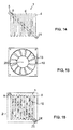
- the bar-shaped holding element 9 does not necessarily extend across the filter layer 4 in a direction perpendicular to the longitudinal axis of the filter elements 9, but may extend diagonally. As shown in figure 14 , the holding element 9 may extend at an angle of about 30° to 60° to the longitudinal axis of the filter elements 6, wherein the holding element 9 extends from a corner of the filter layer 4 to an opposite corner thereof, cf. figure 14 .
- connection of the holding element 9 to the ventilating means 2 does not necessarily include any clamping device 22, but may include a fastening device such as a screw or bolt connection.
- the ends of the holding element 9 extending beyond the circumference of the filter layer 4 may include through holes 24 through which screws or bolts may be connected to the ventilating means 2 or a holder thereof.
- the filter layer 4 of the filter device 1 does not have to be mounted directly by means of the aforementioned holding element 9.
- a mounting frame 26 may be used, which may have a closed ring shape as shown in figure 22 , but also may have an open configuration for example by just having two or three of the four legs 31 of the mounting frame 26 of figure 22 .
- the said mounting frame 26 is provided for indirect mounting the filter layer 4 to any suitable support structure as, for example, the aforementioned drive unit of a ventilator.
- the mounting frame 26 includes an insertion recess 27 which fully overlaps the projected area 28 of the filter layer 4 when viewed in the direction of the airflow 3 and/or perpendicular to the plane defined by the filter layer 4. This enables the filter layer 4 to be inserted and removed into/from the mounting frame 26 in the direction of the airflow 3 and/or perpendicular to the plane defined by the filter layer 4.
- the size and/or the dimensions of the insertion recess 27 is adapted to the size and/or dimensions and/or shape of the filter layer 4 such that the filter layer 4 is held in the insertion recess 27 in a press fitting manner.
- the width of the insertion recess 27 corresponds to the length of the filter layer 4 in the direction of the longitudinal axis of the straight filter sticks. Consequently, the filter sticks may be used as pressure columns providing the necessary friction at the end phases of the filter sticks to ensure fixture of the filter layer 4 in the mounting frame 26.
- the insertion recess In the crosswise direction, that means perpendicular to the longitudinal axis 25 of the filter sticks, the insertion recess may be formed wider than the filter layer 4 so there is no pressure onto the filter sticks perpendicular to the longitudinal axis thereof.
- the filter device 1 includes filter elements 6 which are formed by spiral filter rods 13 and which are supported by a common holding element 9. More particularly, the inner ends 6a of the spiral-shaped filter elements 6 are rigidly connected to a rod-shaped holding element 9.
- the spiral-shaped filter rods are offset relative to each other, wherein there is a rotational offset as well as an axial offset, cf. figure 17 .
- the two spiral-shaped filter rods have basically identical shapes and are rotationally offset relative to each other by approximately 180° so that a first spiral filter rod overlaps the spacings between the legs of the second spiral filter rod when viewed in the direction of the spiral axis or the main direction of the airflow 3. Additionally, there is an axial offset in the direction of the said airflow 3.
- the inner ends 6a of the spiral-shaped filter elements 6 are attached to opposite sides of the circumference of the holding element 9 at different axial positions, cf. figure 17 .
- Such a central holding element 9 supporting the filter elements 6 in a cantilevered fashion maximizes the effective filter surface and minimizes the obstruction thereof by the filter holder 5.
- An advantageous way of mounting the filter device 1 of figure 17 to a ventilating means 2 is shown in figure 18 .
- the central holding element may be used to mount the filter device 1 to the back side of a driving unit 16 of the ventilating means 2, wherein the holding element 9 may be connected to a holder for the said driving unit 16.
- the spiral-shaped filter arrangement may be mounted by means of a mounting frame similar to that shown in figure 22 .
- the mounting frame may be formed circular or may comprise circular sections or segments and may include an insertion recess which fully overlaps the projected area of the filter layer 4 of the filter in figure 22 when viewed in the direction of the airflow and/or perpendicular to the plane defined by the filter layer 4.
- support elements may be provided between the filter layers 4a, 4b for supporting respectively stiffening the filter arrangement to achieve an improved rigidity.
- the support elements may be constructed as separate spacer respectively distance pieces or may be constructed as single piece together with one or more of the filter rods, whereby the support element(s) may protrude substantially perpendicular from the filter rod (i.e. in direction of the main air flow).
- Figures 19 and 20 show another embodiment of spiral-shaped filter elements 6, wherein two spiral-shaped filter rods are shaped complementary to each other.
- the spiral filter rod 6 of figure 20 exactly fits into the spacing 17 between the legs of the other spiral filter rod. In other words, if the two spiral filter rods are positioned in the same plane, a completely closed, void-free panel is defined.
- This complementary shape of the filter elements allows easy manufacturing thereof, for example by cutting such as laser cutting a plate-shaped blank.
- the spiral filter rods of figures 19 and 20 basically may be mounted as it is shown in figures 17 and 18 .
- figure 21 shows two filter elements 6 having a shape of a logarithmic spiral.
- the filter rods forming the filter elements 6 are connected, with their inner ends 6a, to a common core section made of the same material as the filter rods so the spiral filter rods including the core section may be formed integrally in one piece from the same material.
- the said core section therefore may form the holding element 9 to hold the filter elements 6 in the airflow 3 of the ventilating means 2 as described for figure 18 .
- the holding element 9 may comprise preferably bar- or beam-shaped sections 9a extending preferably diametral as shown in figure 21 for supporting respectively stiffening the filter arrangement to achieve an improved rigidity.
- the bar- or beam-shaped sections 9a may comprise a support surface 10 into which at least sections of the filter element 6 are embedded with the circumferential sides of their support section 6d.
Landscapes
- Chemical & Material Sciences (AREA)
- Chemical Kinetics & Catalysis (AREA)
- Engineering & Computer Science (AREA)
- Multimedia (AREA)
- Health & Medical Sciences (AREA)
- General Health & Medical Sciences (AREA)
- Life Sciences & Earth Sciences (AREA)
- Animal Behavior & Ethology (AREA)
- Epidemiology (AREA)
- Public Health (AREA)
- Veterinary Medicine (AREA)
- Materials Engineering (AREA)
- Filtering Of Dispersed Particles In Gases (AREA)
- Respiratory Apparatuses And Protective Means (AREA)
- Pinball Game Machines (AREA)
- Separating Particles In Gases By Inertia (AREA)
Priority Applications (5)
| Application Number | Priority Date | Filing Date | Title |
|---|---|---|---|
| PL14164577.0T PL2756875T3 (pl) | 2009-11-12 | 2009-11-12 | Urządzenie oczyszczające powietrze do usuwania zanieczyszczeń powietrza ze strumienia powietrza |
| EP14164577.0A EP2756875B1 (de) | 2009-11-12 | 2009-11-12 | Luftreiniger zur Entfernung von Luftverunreinigern aus einem Luftstrom |
| PT141645770T PT2756875T (pt) | 2009-11-12 | 2009-11-12 | Purificador de ar para remover poluentes do ar de uma corrente de ar |
| ES14164577.0T ES2582381T3 (es) | 2009-11-12 | 2009-11-12 | Filtro de aire para la eliminación de contaminantes del aire de una corriente de aire |
| HRP20160838TT HRP20160838T1 (hr) | 2009-11-12 | 2016-07-12 | Pročistač zraka za uklanjanje onečišćujućih tvari iz struje zraka |
Applications Claiming Priority (2)
| Application Number | Priority Date | Filing Date | Title |
|---|---|---|---|
| EP14164577.0A EP2756875B1 (de) | 2009-11-12 | 2009-11-12 | Luftreiniger zur Entfernung von Luftverunreinigern aus einem Luftstrom |
| EP09175857.3A EP2327466B1 (de) | 2009-11-12 | 2009-11-12 | Luftreiniger zur Entfernung von Luftverunreinigungen aus einem Luftstrom |
Related Parent Applications (2)
| Application Number | Title | Priority Date | Filing Date |
|---|---|---|---|
| EP09175857.3A Division-Into EP2327466B1 (de) | 2009-11-12 | 2009-11-12 | Luftreiniger zur Entfernung von Luftverunreinigungen aus einem Luftstrom |
| EP09175857.3A Division EP2327466B1 (de) | 2009-11-12 | 2009-11-12 | Luftreiniger zur Entfernung von Luftverunreinigungen aus einem Luftstrom |
Publications (2)
| Publication Number | Publication Date |
|---|---|
| EP2756875A1 true EP2756875A1 (de) | 2014-07-23 |
| EP2756875B1 EP2756875B1 (de) | 2016-04-13 |
Family
ID=41828701
Family Applications (3)
| Application Number | Title | Priority Date | Filing Date |
|---|---|---|---|
| EP13002982.0A Not-in-force EP2638943B1 (de) | 2009-11-12 | 2009-11-12 | Luftreiniger zur entfernung von luftschadstoffen aus einem luftstrom |
| EP14164577.0A Active EP2756875B1 (de) | 2009-11-12 | 2009-11-12 | Luftreiniger zur Entfernung von Luftverunreinigern aus einem Luftstrom |
| EP09175857.3A Active EP2327466B1 (de) | 2009-11-12 | 2009-11-12 | Luftreiniger zur Entfernung von Luftverunreinigungen aus einem Luftstrom |
Family Applications Before (1)
| Application Number | Title | Priority Date | Filing Date |
|---|---|---|---|
| EP13002982.0A Not-in-force EP2638943B1 (de) | 2009-11-12 | 2009-11-12 | Luftreiniger zur entfernung von luftschadstoffen aus einem luftstrom |
Family Applications After (1)
| Application Number | Title | Priority Date | Filing Date |
|---|---|---|---|
| EP09175857.3A Active EP2327466B1 (de) | 2009-11-12 | 2009-11-12 | Luftreiniger zur Entfernung von Luftverunreinigungen aus einem Luftstrom |
Country Status (21)
| Country | Link |
|---|---|
| US (2) | US8696780B2 (de) |
| EP (3) | EP2638943B1 (de) |
| JP (1) | JP5754744B2 (de) |
| KR (1) | KR101708963B1 (de) |
| CN (2) | CN102711950B (de) |
| AU (1) | AU2010318289B2 (de) |
| BR (1) | BR112012011199A2 (de) |
| CA (1) | CA2780797C (de) |
| CY (1) | CY1117314T1 (de) |
| DK (1) | DK2327466T3 (de) |
| ES (3) | ES2519046T3 (de) |
| HR (2) | HRP20140769T1 (de) |
| MX (1) | MX2012005541A (de) |
| PL (2) | PL2327466T3 (de) |
| PT (2) | PT2327466E (de) |
| RU (2) | RU2556112C2 (de) |
| SI (1) | SI2327466T1 (de) |
| SM (1) | SMT201400137B (de) |
| UA (1) | UA109533C2 (de) |
| WO (1) | WO2011057761A2 (de) |
| ZA (1) | ZA201203292B (de) |
Families Citing this family (17)
| Publication number | Priority date | Publication date | Assignee | Title |
|---|---|---|---|---|
| EP1922129B1 (de) * | 2005-09-09 | 2012-08-29 | Dexwet Usa Llc | Filtermodul |
| DE102005048841B3 (de) * | 2005-10-12 | 2007-07-05 | Daimlerchrysler Ag | Luftfilter für eine Belüftungsanlage eines Kraftfahrzeugs |
| PL2327466T3 (pl) * | 2009-11-12 | 2014-11-28 | Novomatic Ag | Urządzenie oczyszczające powietrze do usuwania zanieczyszczeń powietrza ze strumienia powietrza |
| EP2524131A4 (de) * | 2010-01-14 | 2014-05-21 | Husqvarna Ab | Lufteinlasssystem für einen verbrennungsmotor |
| DE202010007120U1 (de) * | 2010-05-21 | 2011-09-07 | Novomatic Ag | Kühlluftreiniger eines Elektronikgeräts |
| US8936662B2 (en) | 2012-10-02 | 2015-01-20 | Integrated Global Services, Inc. | Apparatus and methods for large particle ash separation from flue gas using screens having semi-elliptical cylinder surfaces |
| US20150128807A1 (en) * | 2013-11-13 | 2015-05-14 | Dexwet International AG | Synthetic Injected Hydrophilic Filter System |
| US9180389B2 (en) * | 2013-11-26 | 2015-11-10 | Shenzhen China Star Optoelectronics Technology Co., Ltd | Filter |
| US9320999B2 (en) * | 2014-05-07 | 2016-04-26 | Ned Abell | Method and device for removing airborne pollutants |
| US11890568B2 (en) | 2014-12-18 | 2024-02-06 | Koninklijke Philips N.V. | Air purifier filter system, an air purifier and a method for controlling an air purifier |
| CN105080246B (zh) * | 2015-09-11 | 2016-09-21 | 乐山市红斯玛环保应急装备有限公司 | 一种气体栅格洗涤混合器及方法 |
| CN110614003A (zh) * | 2016-06-15 | 2019-12-27 | 高境 | 去除气溶胶中细颗粒物的方法和系统 |
| CN106693554A (zh) * | 2017-01-23 | 2017-05-24 | 王宇轩 | 一种基于丝线过滤的空气净化器 |
| WO2019208275A1 (ja) * | 2018-04-26 | 2019-10-31 | 東レ株式会社 | 分離膜モジュール |
| CN110975470B (zh) * | 2019-12-19 | 2021-09-10 | 安徽工业大学 | 一种用于高温烟气净化的湿式除尘器 |
| US12157082B2 (en) * | 2021-02-01 | 2024-12-03 | Jin Min Choi | Removable filter system |
| WO2023245140A2 (en) * | 2022-06-17 | 2023-12-21 | Perumala Holdings, LLC | Systems and methods for the preparation of vaccines utilizing predictably inactivated pathogens |
Citations (5)
| Publication number | Priority date | Publication date | Assignee | Title |
|---|---|---|---|---|
| US195656A (en) * | 1877-09-25 | Improvement in draft apparatus for stove-pipes and chimneys | ||
| GB1179883A (en) * | 1967-05-02 | 1970-02-04 | British Aircraft Corp Ltd Form | Improvements relating to apparatus for Removing Liquid Particles from a Gas Stream |
| EP0515759A1 (de) | 1991-05-29 | 1992-12-02 | Jean-Paul Atdjian | Filter zur Reinigung von Luft |
| EP1345669A1 (de) | 2000-05-12 | 2003-09-24 | PDH International Incorporated | Vorrichtung und verfahren für die nassfiltration von maschinenabgasen |
| WO2007028176A1 (de) | 2005-09-09 | 2007-03-15 | Dexwet Usa Llc | Filtermodul |
Family Cites Families (56)
| Publication number | Priority date | Publication date | Assignee | Title |
|---|---|---|---|---|
| GB191028984A (en) * | 1910-12-13 | 1911-12-13 | Allison Hall Lennox | Improvements in Apparatus for Washing Smoke. |
| GB191128984A (en) | 1911-05-02 | 1912-07-25 | Emile De Pianelli De L Valette | An Improved Automatic Apparatus Showing a Series of Luminous Pictures. |
| FR629231A (fr) * | 1927-02-17 | 1927-11-07 | Soc Fr Constr Babcock & Wilcox | Dispositif pour le dépoussiérage des fluides |
| US2286480A (en) * | 1940-07-01 | 1942-06-16 | Morrill N Farr | Air purifier or conditioner |
| GB823542A (en) * | 1956-01-13 | 1959-11-11 | Maurice Wyatt Flood Page | Improvements relating to methods and apparatus for extracting dust and like fragments of burnt or partially burnt solid material from combustion gases |
| CH489259A (de) * | 1968-06-08 | 1970-04-30 | Dietzsch Gmbh Hans Joachim | Verfahren zur Herstellung von kapillaren Austauschern |
| FR2236537B1 (de) * | 1973-07-11 | 1977-12-23 | Rhone Poulenc Ind | |
| JPS5127161A (ja) * | 1974-08-31 | 1976-03-06 | Hisashi Araki | Mizuoryoshitakukiseijosochi |
| US4052315A (en) * | 1974-10-21 | 1977-10-04 | Illinois Tool Works Inc. | One-piece molded filter |
| US4268278A (en) * | 1978-05-16 | 1981-05-19 | Monsanto Company | Inorganic anisotropic hollow fibers |
| US4277263A (en) * | 1979-03-26 | 1981-07-07 | Willard Bergeron | Air and rock particle separator with spiral deflectors |
| FR2471208A1 (fr) * | 1979-12-17 | 1981-06-19 | Commissariat Energie Atomique | Procede et dispositif pour la separation isotopique par diffusion gazeuse |
| GB2154466A (en) * | 1984-01-17 | 1985-09-11 | Fung Chin Pang | Scrubbing gas stream |
| JPS6161607A (ja) * | 1984-09-04 | 1986-03-29 | Ishikawajima Harima Heavy Ind Co Ltd | 除塵用スクリ−ンフイルタの製造方法及び装置 |
| JPS63264111A (ja) * | 1987-04-20 | 1988-11-01 | Arai Tekkosho:Kk | 濾過ないし分離用版状素子 |
| DE3852937T2 (de) * | 1987-12-01 | 1995-09-07 | Asahi Glass Co Ltd | Abgasfilter. |
| FR2639248B1 (fr) * | 1988-11-21 | 1990-12-28 | Lyonnaise Eaux | Carter pour modules de filtration a faisceaux de fibres |
| RU2022620C1 (ru) * | 1989-05-24 | 1994-11-15 | Научно-исследовательский и проектно-конструкторский институт по оборудованию для кондиционирования воздуха и вентиляции | Устройство для очистки воздуха от пыли |
| JPH044011A (ja) * | 1990-04-19 | 1992-01-08 | Mitsui Petrochem Ind Ltd | フィルター |
| US5182019A (en) * | 1990-08-17 | 1993-01-26 | Zenon Environmental Inc. | Cartridge of hybrid frameless arrays of hollow fiber membranes and module containing an assembly of cartridges |
| US5104535A (en) * | 1990-08-17 | 1992-04-14 | Zenon Environmental, Inc. | Frameless array of hollow fiber membranes and module containing a stack of arrays |
| US5264171A (en) * | 1991-12-31 | 1993-11-23 | Hoechst Celanese Corporation | Method of making spiral-wound hollow fiber membrane fabric cartridges and modules having flow-directing baffles |
| NL9200117A (nl) * | 1992-01-22 | 1993-08-16 | Du Pont Nederland | Stelsel en connectoren voor het onderling elektrisch verbinden van componentplaten. |
| US5366625A (en) * | 1992-03-04 | 1994-11-22 | Pedersen Steven K | Cartridge of hybrid unitary wafers of hollow fiber membranes and module containing a stack of post-potted cartridges |
| AU4279493A (en) * | 1992-05-18 | 1993-12-13 | Minntech Corporation | Hollow fiber filter cartridge and method of manufacture |
| JPH06226014A (ja) * | 1993-02-04 | 1994-08-16 | Michiko Arai | 非円版型ワイヤスリットエレメント |
| JPH06261216A (ja) * | 1993-03-04 | 1994-09-16 | Murata Mach Ltd | 画像処理装置 |
| JPH0768136A (ja) * | 1993-09-02 | 1995-03-14 | Tsuchiya Mfg Co Ltd | 中空糸膜型分離モジュ−ル及びその製造方法 |
| FR2712825B1 (fr) * | 1993-11-23 | 1996-02-23 | Jouan | Procédé de traitement par centrifugation d'un liquide conditionné dans des poches à parois souples, reliées à au moins un filtre. |
| EP0693795B1 (de) * | 1994-07-22 | 1999-03-17 | Berg Electronics Manufacturing B.V. | Selektiv metallisierter Verbinder mit mindestens einem koaxialen oder biaxialen Kontakt |
| US5512074A (en) * | 1994-09-19 | 1996-04-30 | Farr Company | Air filter assembly |
| JPH08189678A (ja) * | 1994-12-29 | 1996-07-23 | Keiji Sawai | 遊技施設に設置する換気装置 |
| JP2754359B2 (ja) * | 1995-07-31 | 1998-05-20 | 山岡金属工業株式会社 | 遊技機用空気清浄装置 |
| DE69624492T2 (de) * | 1995-08-11 | 2003-06-26 | Zenon Environmental Inc., Oakville | Vertikaler strang von hohlfasermembranen und verfahren zur aufrechterhaltung sauberer faseroberflächen |
| WO1997017125A1 (en) * | 1995-11-06 | 1997-05-15 | Buxbaum Robert E | Apparatus and methods for gas extraction |
| EP0952885B1 (de) * | 1996-12-20 | 2010-09-22 | Siemens Water Technologies Corp. | Reinigungsmethode |
| CN1223174A (zh) * | 1998-01-16 | 1999-07-21 | 俞其进 | 电子集尘式空气净化器 |
| JP2000005242A (ja) * | 1998-06-24 | 2000-01-11 | Denso Corp | 脱臭装置 |
| DE19925439B4 (de) | 1999-06-02 | 2008-12-11 | Stego-Holding Gmbh | Lüfter |
| DE10022917C5 (de) * | 2000-03-31 | 2005-07-28 | Atech Innovations Gmbh | Filtervorrichtung für die Mikro- und/oder Ultrafiltration |
| US6490782B1 (en) * | 2000-10-16 | 2002-12-10 | Varian, Inc. | Automated in-line filter changing apparatus |
| NL1017061C2 (nl) * | 2001-01-09 | 2002-07-11 | Simon Roelof Vasse | Membraanfilter. |
| DE10211828A1 (de) * | 2002-03-16 | 2003-10-02 | Big Dutchman Int Gmbh | Vorrichtung zum Behandeln wenigstens eines gasförmigen Mediums, insbesondere zum Reinigen von aus Gebäuden abgeführter Luft |
| GB0210448D0 (en) * | 2002-05-08 | 2002-06-12 | 3M Innovative Properties Co | Valve closure for spray gun reservoir |
| DE10227721B4 (de) * | 2002-06-21 | 2008-03-13 | Hermsdorfer Institut Für Technische Keramik E.V. | Verfahren zur Herstellung eines Bündels keramischer Kapillaren für ein Separationsmodul |
| WO2004060539A1 (en) * | 2002-12-19 | 2004-07-22 | Exxonmobil Upstream Research Company | Membrane module for separation of fluids |
| JP4316403B2 (ja) * | 2003-04-03 | 2009-08-19 | Agcマテックス株式会社 | Frp製グレーチングおよびその成形方法 |
| JP2005192605A (ja) * | 2003-12-26 | 2005-07-21 | Aruze Corp | ゲーム機 |
| US8016683B2 (en) * | 2005-10-31 | 2011-09-13 | Cole Kepro International, Llc | Gaming cabinet constructed from connectable components |
| JP4878213B2 (ja) * | 2006-05-19 | 2012-02-15 | 象印マホービン株式会社 | 空気清浄機 |
| UA21395U (en) * | 2006-09-21 | 2007-03-15 | Yuliia Vasylivna Levytska | Juke |
| JP5225601B2 (ja) * | 2007-03-30 | 2013-07-03 | 株式会社コーワ | 空気調和機 |
| EP2152390B1 (de) * | 2007-05-29 | 2012-05-23 | Siemens Industry, Inc. | Membranreinigung mit gepulster mammutpumpe |
| JP2008295522A (ja) * | 2007-05-29 | 2008-12-11 | Aruze Corp | 遊技機 |
| CN103394230B (zh) * | 2008-06-03 | 2015-09-09 | 唐纳森公司 | 具有外部螺纹的旋装过滤器及方法 |
| PL2327466T3 (pl) * | 2009-11-12 | 2014-11-28 | Novomatic Ag | Urządzenie oczyszczające powietrze do usuwania zanieczyszczeń powietrza ze strumienia powietrza |
-
2009
- 2009-11-12 PL PL09175857T patent/PL2327466T3/pl unknown
- 2009-11-12 PT PT91758573T patent/PT2327466E/pt unknown
- 2009-11-12 ES ES09175857.3T patent/ES2519046T3/es active Active
- 2009-11-12 SI SI200930998T patent/SI2327466T1/sl unknown
- 2009-11-12 EP EP13002982.0A patent/EP2638943B1/de not_active Not-in-force
- 2009-11-12 DK DK09175857.3T patent/DK2327466T3/da active
- 2009-11-12 ES ES14164577.0T patent/ES2582381T3/es active Active
- 2009-11-12 EP EP14164577.0A patent/EP2756875B1/de active Active
- 2009-11-12 PL PL14164577.0T patent/PL2756875T3/pl unknown
- 2009-11-12 ES ES13002982T patent/ES2864876T3/es active Active
- 2009-11-12 PT PT141645770T patent/PT2756875T/pt unknown
- 2009-11-12 EP EP09175857.3A patent/EP2327466B1/de active Active
-
2010
- 2010-09-11 UA UAA201205707A patent/UA109533C2/ru unknown
- 2010-11-09 RU RU2012121955/05A patent/RU2556112C2/ru active
- 2010-11-09 CN CN201080059984.0A patent/CN102711950B/zh active Active
- 2010-11-09 KR KR1020127014761A patent/KR101708963B1/ko not_active Expired - Fee Related
- 2010-11-09 BR BR112012011199A patent/BR112012011199A2/pt not_active Application Discontinuation
- 2010-11-09 WO PCT/EP2010/006825 patent/WO2011057761A2/en not_active Ceased
- 2010-11-09 MX MX2012005541A patent/MX2012005541A/es active IP Right Grant
- 2010-11-09 JP JP2012538232A patent/JP5754744B2/ja not_active Expired - Fee Related
- 2010-11-09 RU RU2015120623A patent/RU2685347C2/ru active
- 2010-11-09 US US12/942,615 patent/US8696780B2/en not_active Expired - Fee Related
- 2010-11-09 CA CA2780797A patent/CA2780797C/en not_active Expired - Fee Related
- 2010-11-09 CN CN201510161881.XA patent/CN104826401B/zh active Active
- 2010-11-09 AU AU2010318289A patent/AU2010318289B2/en not_active Ceased
-
2012
- 2012-05-07 ZA ZA2012/03292A patent/ZA201203292B/en unknown
-
2014
- 2014-02-26 US US14/190,852 patent/US9566504B2/en active Active
- 2014-08-14 HR HRP20140769AT patent/HRP20140769T1/hr unknown
- 2014-08-25 CY CY20141100679T patent/CY1117314T1/el unknown
- 2014-09-19 SM SM201400137T patent/SMT201400137B/xx unknown
-
2016
- 2016-07-12 HR HRP20160838TT patent/HRP20160838T1/hr unknown
Patent Citations (5)
| Publication number | Priority date | Publication date | Assignee | Title |
|---|---|---|---|---|
| US195656A (en) * | 1877-09-25 | Improvement in draft apparatus for stove-pipes and chimneys | ||
| GB1179883A (en) * | 1967-05-02 | 1970-02-04 | British Aircraft Corp Ltd Form | Improvements relating to apparatus for Removing Liquid Particles from a Gas Stream |
| EP0515759A1 (de) | 1991-05-29 | 1992-12-02 | Jean-Paul Atdjian | Filter zur Reinigung von Luft |
| EP1345669A1 (de) | 2000-05-12 | 2003-09-24 | PDH International Incorporated | Vorrichtung und verfahren für die nassfiltration von maschinenabgasen |
| WO2007028176A1 (de) | 2005-09-09 | 2007-03-15 | Dexwet Usa Llc | Filtermodul |
Also Published As
Similar Documents
| Publication | Publication Date | Title |
|---|---|---|
| EP2638943B1 (de) | Luftreiniger zur entfernung von luftschadstoffen aus einem luftstrom | |
| JP5471956B2 (ja) | 加湿ユニットおよびそれを搭載した加湿装置 | |
| KR20120033590A (ko) | 필터 간격을 조절할 수 있는 공기청정기 | |
| JP6321319B2 (ja) | フィルタ清掃装置及びそれを備えた空気調和機 | |
| EP3040637B1 (de) | Luftausgabeeinheit und klimaanlage damit | |
| JP2012042124A (ja) | 加湿装置 | |
| CN106457113A (zh) | 合成注入的亲水性过滤器系统 | |
| HK1189542A (en) | Air cleaner for removing air pollutants from an air stream | |
| KR102658322B1 (ko) | 공기청정 송풍장치 | |
| HK1189542B (en) | Air cleaner for removing air pollutants from an air stream | |
| HK1176327A (en) | Air cleaner for removing air pollutants from an air stream | |
| HK1213525B (en) | Air cleaner for removing air pollutants from an air stream | |
| CN108592212B (zh) | 空气净化装置 | |
| CN219845426U (zh) | 机体组件及吹风机 | |
| KR20200095956A (ko) | 공기조화기 | |
| KR102256965B1 (ko) | 공기흡입부의 넓이 조절이 가능한 공기청정기 | |
| KR20130077039A (ko) | 공기 청정기 | |
| KR20220142859A (ko) | 공기청정기 | |
| JP2012161487A (ja) | 空気清浄機 |
Legal Events
| Date | Code | Title | Description |
|---|---|---|---|
| PUAI | Public reference made under article 153(3) epc to a published international application that has entered the european phase |
Free format text: ORIGINAL CODE: 0009012 |
|
| 17P | Request for examination filed |
Effective date: 20140414 |
|
| AC | Divisional application: reference to earlier application |
Ref document number: 2327466 Country of ref document: EP Kind code of ref document: P |
|
| AK | Designated contracting states |
Kind code of ref document: A1 Designated state(s): AT BE BG CH CY CZ DE DK EE ES FI FR GB GR HR HU IE IS IT LI LT LU LV MC MK MT NL NO PL PT RO SE SI SK SM TR |
|
| R17P | Request for examination filed (corrected) |
Effective date: 20150122 |
|
| RBV | Designated contracting states (corrected) |
Designated state(s): AT BE BG CH CY CZ DE DK EE ES FI FR GB GR HR HU IE IS IT LI LT LU LV MC MK MT NL NO PL PT RO SE SI SK SM TR |
|
| 17Q | First examination report despatched |
Effective date: 20150724 |
|
| REG | Reference to a national code |
Ref country code: DE Ref legal event code: R079 Ref document number: 602009037892 Country of ref document: DE Free format text: PREVIOUS MAIN CLASS: B01D0045100000 Ipc: A63F0013000000 |
|
| GRAP | Despatch of communication of intention to grant a patent |
Free format text: ORIGINAL CODE: EPIDOSNIGR1 |
|
| RIC1 | Information provided on ipc code assigned before grant |
Ipc: B01D 45/10 20060101ALI20150924BHEP Ipc: A61L 9/014 20060101ALI20150924BHEP Ipc: A63F 13/00 20140101AFI20150924BHEP Ipc: B01D 47/02 20060101ALI20150924BHEP Ipc: B01D 46/00 20060101ALI20150924BHEP |
|
| INTG | Intention to grant announced |
Effective date: 20151023 |
|
| GRAS | Grant fee paid |
Free format text: ORIGINAL CODE: EPIDOSNIGR3 |
|
| GRAA | (expected) grant |
Free format text: ORIGINAL CODE: 0009210 |
|
| AC | Divisional application: reference to earlier application |
Ref document number: 2327466 Country of ref document: EP Kind code of ref document: P |
|
| AK | Designated contracting states |
Kind code of ref document: B1 Designated state(s): AT BE BG CH CY CZ DE DK EE ES FI FR GB GR HR HU IE IS IT LI LT LU LV MC MK MT NL NO PL PT RO SE SI SK SM TR |
|
| REG | Reference to a national code |
Ref country code: GB Ref legal event code: FG4D |
|
| REG | Reference to a national code |
Ref country code: AT Ref legal event code: REF Ref document number: 789490 Country of ref document: AT Kind code of ref document: T Effective date: 20160415 Ref country code: CH Ref legal event code: EP |
|
| REG | Reference to a national code |
Ref country code: IE Ref legal event code: FG4D |
|
| REG | Reference to a national code |
Ref country code: DE Ref legal event code: R096 Ref document number: 602009037892 Country of ref document: DE |
|
| REG | Reference to a national code |
Ref country code: HR Ref legal event code: TUEP Ref document number: P20160838 Country of ref document: HR Ref country code: RO Ref legal event code: EPE |
|
| REG | Reference to a national code |
Ref country code: PT Ref legal event code: SC4A Ref document number: 2756875 Country of ref document: PT Date of ref document: 20160719 Kind code of ref document: T Free format text: AVAILABILITY OF NATIONAL TRANSLATION Effective date: 20160713 |
|
| REG | Reference to a national code |
Ref country code: CH Ref legal event code: NV Representative=s name: KELLER AND PARTNER PATENTANWAELTE AG, CH |
|
| REG | Reference to a national code |
Ref country code: LT Ref legal event code: MG4D Ref country code: NL Ref legal event code: FP |
|
| REG | Reference to a national code |
Ref country code: ES Ref legal event code: FG2A Ref document number: 2582381 Country of ref document: ES Kind code of ref document: T3 Effective date: 20160912 |
|
| REG | Reference to a national code |
Ref country code: HR Ref legal event code: T1PR Ref document number: P20160838 Country of ref document: HR |
|
| PG25 | Lapsed in a contracting state [announced via postgrant information from national office to epo] |
Ref country code: LT Free format text: LAPSE BECAUSE OF FAILURE TO SUBMIT A TRANSLATION OF THE DESCRIPTION OR TO PAY THE FEE WITHIN THE PRESCRIBED TIME-LIMIT Effective date: 20160413 Ref country code: FI Free format text: LAPSE BECAUSE OF FAILURE TO SUBMIT A TRANSLATION OF THE DESCRIPTION OR TO PAY THE FEE WITHIN THE PRESCRIBED TIME-LIMIT Effective date: 20160413 Ref country code: NO Free format text: LAPSE BECAUSE OF FAILURE TO SUBMIT A TRANSLATION OF THE DESCRIPTION OR TO PAY THE FEE WITHIN THE PRESCRIBED TIME-LIMIT Effective date: 20160713 |
|
| REG | Reference to a national code |
Ref country code: FR Ref legal event code: PLFP Year of fee payment: 8 |
|
| PG25 | Lapsed in a contracting state [announced via postgrant information from national office to epo] |
Ref country code: LV Free format text: LAPSE BECAUSE OF FAILURE TO SUBMIT A TRANSLATION OF THE DESCRIPTION OR TO PAY THE FEE WITHIN THE PRESCRIBED TIME-LIMIT Effective date: 20160413 Ref country code: GR Free format text: LAPSE BECAUSE OF FAILURE TO SUBMIT A TRANSLATION OF THE DESCRIPTION OR TO PAY THE FEE WITHIN THE PRESCRIBED TIME-LIMIT Effective date: 20160714 Ref country code: SE Free format text: LAPSE BECAUSE OF FAILURE TO SUBMIT A TRANSLATION OF THE DESCRIPTION OR TO PAY THE FEE WITHIN THE PRESCRIBED TIME-LIMIT Effective date: 20160413 |
|
| REG | Reference to a national code |
Ref country code: DE Ref legal event code: R097 Ref document number: 602009037892 Country of ref document: DE |
|
| PG25 | Lapsed in a contracting state [announced via postgrant information from national office to epo] |
Ref country code: SK Free format text: LAPSE BECAUSE OF FAILURE TO SUBMIT A TRANSLATION OF THE DESCRIPTION OR TO PAY THE FEE WITHIN THE PRESCRIBED TIME-LIMIT Effective date: 20160413 Ref country code: DK Free format text: LAPSE BECAUSE OF FAILURE TO SUBMIT A TRANSLATION OF THE DESCRIPTION OR TO PAY THE FEE WITHIN THE PRESCRIBED TIME-LIMIT Effective date: 20160413 Ref country code: EE Free format text: LAPSE BECAUSE OF FAILURE TO SUBMIT A TRANSLATION OF THE DESCRIPTION OR TO PAY THE FEE WITHIN THE PRESCRIBED TIME-LIMIT Effective date: 20160413 |
|
| PLBE | No opposition filed within time limit |
Free format text: ORIGINAL CODE: 0009261 |
|
| STAA | Information on the status of an ep patent application or granted ep patent |
Free format text: STATUS: NO OPPOSITION FILED WITHIN TIME LIMIT |
|
| PG25 | Lapsed in a contracting state [announced via postgrant information from national office to epo] |
Ref country code: SM Free format text: LAPSE BECAUSE OF FAILURE TO SUBMIT A TRANSLATION OF THE DESCRIPTION OR TO PAY THE FEE WITHIN THE PRESCRIBED TIME-LIMIT Effective date: 20160413 |
|
| 26N | No opposition filed |
Effective date: 20170116 |
|
| PG25 | Lapsed in a contracting state [announced via postgrant information from national office to epo] |
Ref country code: SI Free format text: LAPSE BECAUSE OF FAILURE TO SUBMIT A TRANSLATION OF THE DESCRIPTION OR TO PAY THE FEE WITHIN THE PRESCRIBED TIME-LIMIT Effective date: 20160413 |
|
| REG | Reference to a national code |
Ref country code: IE Ref legal event code: MM4A |
|
| PG25 | Lapsed in a contracting state [announced via postgrant information from national office to epo] |
Ref country code: LU Free format text: LAPSE BECAUSE OF NON-PAYMENT OF DUE FEES Effective date: 20161130 |
|
| REG | Reference to a national code |
Ref country code: FR Ref legal event code: PLFP Year of fee payment: 9 |
|
| PG25 | Lapsed in a contracting state [announced via postgrant information from national office to epo] |
Ref country code: IE Free format text: LAPSE BECAUSE OF NON-PAYMENT OF DUE FEES Effective date: 20161112 |
|
| PG25 | Lapsed in a contracting state [announced via postgrant information from national office to epo] |
Ref country code: HU Free format text: LAPSE BECAUSE OF FAILURE TO SUBMIT A TRANSLATION OF THE DESCRIPTION OR TO PAY THE FEE WITHIN THE PRESCRIBED TIME-LIMIT; INVALID AB INITIO Effective date: 20091112 |
|
| PG25 | Lapsed in a contracting state [announced via postgrant information from national office to epo] |
Ref country code: IS Free format text: LAPSE BECAUSE OF FAILURE TO SUBMIT A TRANSLATION OF THE DESCRIPTION OR TO PAY THE FEE WITHIN THE PRESCRIBED TIME-LIMIT Effective date: 20160413 Ref country code: CY Free format text: LAPSE BECAUSE OF FAILURE TO SUBMIT A TRANSLATION OF THE DESCRIPTION OR TO PAY THE FEE WITHIN THE PRESCRIBED TIME-LIMIT Effective date: 20160413 |
|
| PG25 | Lapsed in a contracting state [announced via postgrant information from national office to epo] |
Ref country code: BG Free format text: LAPSE BECAUSE OF FAILURE TO SUBMIT A TRANSLATION OF THE DESCRIPTION OR TO PAY THE FEE WITHIN THE PRESCRIBED TIME-LIMIT Effective date: 20160413 |
|
| PG25 | Lapsed in a contracting state [announced via postgrant information from national office to epo] |
Ref country code: MT Free format text: LAPSE BECAUSE OF NON-PAYMENT OF DUE FEES Effective date: 20161112 |
|
| REG | Reference to a national code |
Ref country code: HR Ref legal event code: ODRP Ref document number: P20160838 Country of ref document: HR Payment date: 20181105 Year of fee payment: 10 |
|
| REG | Reference to a national code |
Ref country code: AT Ref legal event code: UEP Ref document number: 789490 Country of ref document: AT Kind code of ref document: T Effective date: 20160413 |
|
| REG | Reference to a national code |
Ref country code: HR Ref legal event code: ODRP Ref document number: P20160838 Country of ref document: HR Payment date: 20191104 Year of fee payment: 11 |
|
| PGFP | Annual fee paid to national office [announced via postgrant information from national office to epo] |
Ref country code: RO Payment date: 20191105 Year of fee payment: 11 Ref country code: PT Payment date: 20191105 Year of fee payment: 11 Ref country code: MC Payment date: 20191121 Year of fee payment: 11 |
|
| PGFP | Annual fee paid to national office [announced via postgrant information from national office to epo] |
Ref country code: HR Payment date: 20191104 Year of fee payment: 11 |
|
| PGFP | Annual fee paid to national office [announced via postgrant information from national office to epo] |
Ref country code: MK Payment date: 20191105 Year of fee payment: 11 Ref country code: TR Payment date: 20191108 Year of fee payment: 11 Ref country code: CH Payment date: 20191125 Year of fee payment: 11 |
|
| REG | Reference to a national code |
Ref country code: CH Ref legal event code: PFA Owner name: NOVOMATIC AG, US Free format text: FORMER OWNER: NOVOMATIC AG, US |
|
| PGFP | Annual fee paid to national office [announced via postgrant information from national office to epo] |
Ref country code: NL Payment date: 20201119 Year of fee payment: 12 |
|
| PGFP | Annual fee paid to national office [announced via postgrant information from national office to epo] |
Ref country code: IT Payment date: 20201130 Year of fee payment: 12 Ref country code: ES Payment date: 20201214 Year of fee payment: 12 Ref country code: GB Payment date: 20201123 Year of fee payment: 12 Ref country code: FR Payment date: 20201120 Year of fee payment: 12 Ref country code: DE Payment date: 20201125 Year of fee payment: 12 Ref country code: AT Payment date: 20201117 Year of fee payment: 12 Ref country code: CZ Payment date: 20201102 Year of fee payment: 12 |
|
| PGFP | Annual fee paid to national office [announced via postgrant information from national office to epo] |
Ref country code: BE Payment date: 20201119 Year of fee payment: 12 Ref country code: PL Payment date: 20201103 Year of fee payment: 12 |
|
| REG | Reference to a national code |
Ref country code: HR Ref legal event code: PBON Ref document number: P20160838 Country of ref document: HR Effective date: 20201112 |
|
| PG25 | Lapsed in a contracting state [announced via postgrant information from national office to epo] |
Ref country code: MC Free format text: LAPSE BECAUSE OF NON-PAYMENT OF DUE FEES Effective date: 20201130 |
|
| REG | Reference to a national code |
Ref country code: CH Ref legal event code: PL |
|
| PG25 | Lapsed in a contracting state [announced via postgrant information from national office to epo] |
Ref country code: PT Free format text: LAPSE BECAUSE OF NON-PAYMENT OF DUE FEES Effective date: 20210512 Ref country code: RO Free format text: LAPSE BECAUSE OF NON-PAYMENT OF DUE FEES Effective date: 20201112 Ref country code: HR Free format text: LAPSE BECAUSE OF NON-PAYMENT OF DUE FEES Effective date: 20201112 |
|
| PG25 | Lapsed in a contracting state [announced via postgrant information from national office to epo] |
Ref country code: LI Free format text: LAPSE BECAUSE OF NON-PAYMENT OF DUE FEES Effective date: 20201130 Ref country code: CH Free format text: LAPSE BECAUSE OF NON-PAYMENT OF DUE FEES Effective date: 20201130 |
|
| REG | Reference to a national code |
Ref country code: DE Ref legal event code: R119 Ref document number: 602009037892 Country of ref document: DE |
|
| PG25 | Lapsed in a contracting state [announced via postgrant information from national office to epo] |
Ref country code: TR Free format text: LAPSE BECAUSE OF NON-PAYMENT OF DUE FEES Effective date: 20201112 |
|
| REG | Reference to a national code |
Ref country code: NL Ref legal event code: MM Effective date: 20211201 |
|
| REG | Reference to a national code |
Ref country code: AT Ref legal event code: MM01 Ref document number: 789490 Country of ref document: AT Kind code of ref document: T Effective date: 20211112 |
|
| GBPC | Gb: european patent ceased through non-payment of renewal fee |
Effective date: 20211112 |
|
| PG25 | Lapsed in a contracting state [announced via postgrant information from national office to epo] |
Ref country code: CZ Free format text: LAPSE BECAUSE OF NON-PAYMENT OF DUE FEES Effective date: 20211112 Ref country code: BE Free format text: LAPSE BECAUSE OF NON-PAYMENT OF DUE FEES Effective date: 20211130 |
|
| REG | Reference to a national code |
Ref country code: BE Ref legal event code: MM Effective date: 20211130 |
|
| PG25 | Lapsed in a contracting state [announced via postgrant information from national office to epo] |
Ref country code: AT Free format text: LAPSE BECAUSE OF NON-PAYMENT OF DUE FEES Effective date: 20211112 |
|
| PG25 | Lapsed in a contracting state [announced via postgrant information from national office to epo] |
Ref country code: NL Free format text: LAPSE BECAUSE OF NON-PAYMENT OF DUE FEES Effective date: 20211201 |
|
| PG25 | Lapsed in a contracting state [announced via postgrant information from national office to epo] |
Ref country code: GB Free format text: LAPSE BECAUSE OF NON-PAYMENT OF DUE FEES Effective date: 20211112 Ref country code: DE Free format text: LAPSE BECAUSE OF NON-PAYMENT OF DUE FEES Effective date: 20220601 |
|
| PG25 | Lapsed in a contracting state [announced via postgrant information from national office to epo] |
Ref country code: FR Free format text: LAPSE BECAUSE OF NON-PAYMENT OF DUE FEES Effective date: 20211130 |
|
| PG25 | Lapsed in a contracting state [announced via postgrant information from national office to epo] |
Ref country code: IT Free format text: LAPSE BECAUSE OF NON-PAYMENT OF DUE FEES Effective date: 20211112 |
|
| REG | Reference to a national code |
Ref country code: ES Ref legal event code: FD2A Effective date: 20230224 |
|
| PG25 | Lapsed in a contracting state [announced via postgrant information from national office to epo] |
Ref country code: ES Free format text: LAPSE BECAUSE OF NON-PAYMENT OF DUE FEES Effective date: 20211113 |
|
| PG25 | Lapsed in a contracting state [announced via postgrant information from national office to epo] |
Ref country code: PL Free format text: LAPSE BECAUSE OF NON-PAYMENT OF DUE FEES Effective date: 20211112 |