EP2763771B1 - Procédé et appareil de purification chromatographique - Google Patents
Procédé et appareil de purification chromatographique Download PDFInfo
- Publication number
- EP2763771B1 EP2763771B1 EP12759658.3A EP12759658A EP2763771B1 EP 2763771 B1 EP2763771 B1 EP 2763771B1 EP 12759658 A EP12759658 A EP 12759658A EP 2763771 B1 EP2763771 B1 EP 2763771B1
- Authority
- EP
- European Patent Office
- Prior art keywords
- separation unit
- target molecule
- separation
- buffer
- outlet
- Prior art date
- Legal status (The legal status is an assumption and is not a legal conclusion. Google has not performed a legal analysis and makes no representation as to the accuracy of the status listed.)
- Active
Links
Images



Classifications
-
- B—PERFORMING OPERATIONS; TRANSPORTING
- B01—PHYSICAL OR CHEMICAL PROCESSES OR APPARATUS IN GENERAL
- B01D—SEPARATION
- B01D15/00—Separating processes involving the treatment of liquids with solid sorbents; Apparatus therefor
- B01D15/08—Selective adsorption, e.g. chromatography
- B01D15/26—Selective adsorption, e.g. chromatography characterised by the separation mechanism
- B01D15/36—Selective adsorption, e.g. chromatography characterised by the separation mechanism involving ionic interaction, e.g. ion-exchange, ion-pair, ion-suppression or ion-exclusion
- B01D15/361—Ion-exchange
-
- B—PERFORMING OPERATIONS; TRANSPORTING
- B01—PHYSICAL OR CHEMICAL PROCESSES OR APPARATUS IN GENERAL
- B01D—SEPARATION
- B01D15/00—Separating processes involving the treatment of liquids with solid sorbents; Apparatus therefor
- B01D15/08—Selective adsorption, e.g. chromatography
- B01D15/10—Selective adsorption, e.g. chromatography characterised by constructional or operational features
- B01D15/18—Selective adsorption, e.g. chromatography characterised by constructional or operational features relating to flow patterns
- B01D15/1864—Selective adsorption, e.g. chromatography characterised by constructional or operational features relating to flow patterns using two or more columns
-
- B—PERFORMING OPERATIONS; TRANSPORTING
- B01—PHYSICAL OR CHEMICAL PROCESSES OR APPARATUS IN GENERAL
- B01D—SEPARATION
- B01D15/00—Separating processes involving the treatment of liquids with solid sorbents; Apparatus therefor
- B01D15/08—Selective adsorption, e.g. chromatography
- B01D15/26—Selective adsorption, e.g. chromatography characterised by the separation mechanism
- B01D15/36—Selective adsorption, e.g. chromatography characterised by the separation mechanism involving ionic interaction, e.g. ion-exchange, ion-pair, ion-suppression or ion-exclusion
- B01D15/361—Ion-exchange
- B01D15/362—Cation-exchange
-
- B—PERFORMING OPERATIONS; TRANSPORTING
- B01—PHYSICAL OR CHEMICAL PROCESSES OR APPARATUS IN GENERAL
- B01D—SEPARATION
- B01D15/00—Separating processes involving the treatment of liquids with solid sorbents; Apparatus therefor
- B01D15/08—Selective adsorption, e.g. chromatography
- B01D15/26—Selective adsorption, e.g. chromatography characterised by the separation mechanism
- B01D15/36—Selective adsorption, e.g. chromatography characterised by the separation mechanism involving ionic interaction, e.g. ion-exchange, ion-pair, ion-suppression or ion-exclusion
- B01D15/361—Ion-exchange
- B01D15/363—Anion-exchange
-
- B—PERFORMING OPERATIONS; TRANSPORTING
- B01—PHYSICAL OR CHEMICAL PROCESSES OR APPARATUS IN GENERAL
- B01D—SEPARATION
- B01D15/00—Separating processes involving the treatment of liquids with solid sorbents; Apparatus therefor
- B01D15/08—Selective adsorption, e.g. chromatography
- B01D15/26—Selective adsorption, e.g. chromatography characterised by the separation mechanism
- B01D15/38—Selective adsorption, e.g. chromatography characterised by the separation mechanism involving specific interaction not covered by one or more of groups B01D15/265 and B01D15/30 - B01D15/36, e.g. affinity, ligand exchange or chiral chromatography
- B01D15/3804—Affinity chromatography
-
- G—PHYSICS
- G01—MEASURING; TESTING
- G01N—INVESTIGATING OR ANALYSING MATERIALS BY DETERMINING THEIR CHEMICAL OR PHYSICAL PROPERTIES
- G01N30/00—Investigating or analysing materials by separation into components using adsorption, absorption or similar phenomena or using ion-exchange, e.g. chromatography or field flow fractionation
- G01N30/02—Column chromatography
- G01N30/26—Conditioning of the fluid carrier; Flow patterns
- G01N30/38—Flow patterns
- G01N30/46—Flow patterns using more than one column
- G01N30/461—Flow patterns using more than one column with serial coupling of separation columns
-
- G—PHYSICS
- G01—MEASURING; TESTING
- G01N—INVESTIGATING OR ANALYSING MATERIALS BY DETERMINING THEIR CHEMICAL OR PHYSICAL PROPERTIES
- G01N30/00—Investigating or analysing materials by separation into components using adsorption, absorption or similar phenomena or using ion-exchange, e.g. chromatography or field flow fractionation
- G01N30/02—Column chromatography
- G01N30/26—Conditioning of the fluid carrier; Flow patterns
- G01N30/38—Flow patterns
- G01N30/46—Flow patterns using more than one column
- G01N30/466—Flow patterns using more than one column with separation columns in parallel
- G01N30/467—Flow patterns using more than one column with separation columns in parallel all columns being identical
-
- G—PHYSICS
- G01—MEASURING; TESTING
- G01N—INVESTIGATING OR ANALYSING MATERIALS BY DETERMINING THEIR CHEMICAL OR PHYSICAL PROPERTIES
- G01N30/00—Investigating or analysing materials by separation into components using adsorption, absorption or similar phenomena or using ion-exchange, e.g. chromatography or field flow fractionation
- G01N30/02—Column chromatography
- G01N30/26—Conditioning of the fluid carrier; Flow patterns
- G01N30/38—Flow patterns
- G01N30/46—Flow patterns using more than one column
- G01N30/468—Flow patterns using more than one column involving switching between different column configurations
-
- G—PHYSICS
- G01—MEASURING; TESTING
- G01N—INVESTIGATING OR ANALYSING MATERIALS BY DETERMINING THEIR CHEMICAL OR PHYSICAL PROPERTIES
- G01N30/00—Investigating or analysing materials by separation into components using adsorption, absorption or similar phenomena or using ion-exchange, e.g. chromatography or field flow fractionation
- G01N30/02—Column chromatography
- G01N30/88—Integrated analysis systems specially adapted therefor, not covered by a single one of the groups G01N30/04 - G01N30/86
- G01N2030/8809—Integrated analysis systems specially adapted therefor, not covered by a single one of the groups G01N30/04 - G01N30/86 analysis specially adapted for the sample
- G01N2030/8813—Integrated analysis systems specially adapted therefor, not covered by a single one of the groups G01N30/04 - G01N30/86 analysis specially adapted for the sample biological materials
- G01N2030/8831—Integrated analysis systems specially adapted therefor, not covered by a single one of the groups G01N30/04 - G01N30/86 analysis specially adapted for the sample biological materials involving peptides or proteins
-
- G—PHYSICS
- G01—MEASURING; TESTING
- G01N—INVESTIGATING OR ANALYSING MATERIALS BY DETERMINING THEIR CHEMICAL OR PHYSICAL PROPERTIES
- G01N30/00—Investigating or analysing materials by separation into components using adsorption, absorption or similar phenomena or using ion-exchange, e.g. chromatography or field flow fractionation
- G01N30/96—Investigating or analysing materials by separation into components using adsorption, absorption or similar phenomena or using ion-exchange, e.g. chromatography or field flow fractionation using ion-exchange
Definitions
- the present invention relates to a method and an apparatus suitable for a continuous chromatography process which only needs three separation columns.
- the process is a two step procedure comprising two chromatographic steps.
- the first chromatographic step (capture) is performed alternating and sequentially on preferably two separation columns, the second chromatographic step (polishing) is performed, also sequentially, on the third column.
- proteins are produced by cell culture, using either mammalian or bacterial cell lines engineered to produce the protein of interest by insertion of a recombinant plasmid containing the gene for that protein. Since the cell lines used are living organisms, they must be fed with a complex growth medium, containing sugars, amino acids, and growth factors, usually supplied from preparations of animal serum. Separation of the desired protein from the mixture of compounds fed to the cells and from the byproducts of the cells themselves to a purity sufficient for use as a human therapeutic poses a daunting challenge.
- Procedures for purification of proteins from cell debris initially depend on the site of expression of the protein. Some proteins are caused to be secreted directly from the cell into the surrounding growth media; others are made intracellularly.
- the first step of a purification process involves lysis of the cell, which can be done by a variety of methods, including mechanical shear, osmotic shock, or enzymatic treatments. Such disruption releases the entire contents of the cell into the homogenate, and in addition produces subcellular fragments that are difficult to remove due to their small size. These are generally removed by centrifugation or by filtration. The same problem arises, although on a smaller scale, with directly secreted proteins due to the natural death of cells and release of intracellular host cell proteins in the course of the protein production run.
- the chromatographic techniques typically separate mixtures of proteins on the basis of their charge, degree of hydrophobicity, or size.
- chromatography resins are available for each of these techniques, allowing accurate tailoring of the purification scheme to the particular protein involved.
- the essence of each of these separation methods is that proteins can be caused either to move at different rates down a long column, achieving a physical separation that increases as they pass further down the column, or to adhere selectively to the separation medium, being then differentially eluted by different solvents.
- the desired protein is separated from impurities when the impurities specifically adhere to the column, and the protein of interest does not, that is, the protein of interest is present in the "flow-through.”
- Ion-exchange chromatography is a procedure applicable to purification of ionizable molecules. Ionized molecules are separated on the basis of the non-specific electrostatic interaction of their charged groups with oppositely charged molecules attached to the solid phase support matrix, thereby retarding those ionized molecules that interact more strongly with solid phase.
- the net charge of each type of ionized molecule, and its affinity for the matrix varies according to the number of charged groups, the charge of each group, and the nature of the molecules competing for interaction with the charged solid phase matrix. These differences result in resolution of various molecule types by ion-exchange chromatography.
- ion exchange chromatography In typical protein purification using ion exchange chromatography, a mixture of many proteins derived from a host cell, such as in mammalian cell culture, is applied to an ion-exchange column. After non-binding molecules are washed away, conditions are adjusted, such as by changing pH, counter ion concentration and the like in step-or gradient-mode, to release from the solid phase a non-specifically retained or retarded ionized protein of interest and separating it from proteins having different charge characteristics.
- Anion exchange chromatography involves competition of an anionic molecule of interest with the negative counter ion for interaction with a positively charged molecule attached to the solid phase matrix at the pH and under the conditions of a particular separation process.
- cation exchange chromatography involves competition of a cationic molecule of interest with the positive counter ion for a negatively charged molecule attached to the solid phase matrix at the pH and under the conditions of a particular separation process.
- Mixed mode ion exchange chromatography involves the use of a combination of cation and anion exchange chromatographic media in the same step.
- “mixed-mode” refers to a solid phase support matrix to which is covalently attached a mixture of cation exchange and/or anion exchange and hydrophobic interaction moieties.
- Affinity chromatography which exploits a specific structurally dependent (i.e., spatially complementary) interaction between the protein to be purified and an immobilized capture agent, is a standard purification option for some proteins, such as antibodies.
- Protein A for example, is a useful adsorbent for affinity chromatography of proteins, such as antibodies, which contain an Fc region.
- Protein A is a 41kD cell wall protein from Staphylococcus aureas which binds with a high affinity (about 10 -8 M to human IgG) to the Fc region of antibodies.
- affinity chromatography is costly, particularly at the industrial scale necessary to purify therapeutic proteins.
- chromatographic methods are Hydroxyapatite chromatography or Hydrophobic interaction chromatography (HIC).
- typical purification processes include different centrifugation and filtration steps as well as at least 3 chromatographic separation techniques such as affinity chromatography (AC), gel permeation chromatography (GPC), ion exchange chromatography (IEC), hydrophobic interaction chromatography (HIC), reversed phase chromatography (RPC), and normal phase chromatography (NPC).
- AC affinity chromatography
- GPC gel permeation chromatography
- IEC ion exchange chromatography
- HIC hydrophobic interaction chromatography
- RPC reversed phase chromatography
- NPC normal phase chromatography
- a more efficient and economic purification process might be achieved by eliminating the sample folding/preparation steps in between the purification steps by direct combination of various chromatographic modes in one purification train.
- Simple batch chromatography technique is well accepted in the industrial applications, however this technology is expensive due to long processing times and high operation costs (e.g. large solvent amounts, expensive resins and hardware). This technique is also sensitive to operational conditions (e.g. product titer, residence time and feeding rate (product losses starting from 80% dynamic binding capacity values).
- WO 2011/037522 discloses a separation system comprising at least two separation units which are connected outlet to inlet. All columns are connected in line.
- WO 2011/017514 discloses the combination of an affinity chromatography step and two ion exchange chromatography steps without the need for holding tanks or buffer exchange steps.
- WO 2009/045897 discloses systems and methods for purifying proteins whereby several different chromatography columns are in series with intermediate steps.
- the present invention is thus directed to an apparatus comprising
- the separation units A1 and A2 have an affinity chromatography, a cation exchange, an anion exchange chromatography matrix or a mixed mode cation exchange matrix.
- the separation unit B has a cation exchange, a mixed mode anion exchange or an anion exchange chromatography matrix.
- the separation unit B has a mixture of matrixes including a cation exchange and an anion exchange chromatography matrix or a cation and a mixed mode anion exchange matrix or a mixed mode cation exchange matrix and an anion exchange matrix.
- the separation units A1 and A2 have an affinity chromatography matrix and the separation unit B has a cation exchange chromatography matrix.
- the separation units A1 and A2 have an affinity chromatography matrix and the separation unit B has an anion exchange or a mixed mode anion exchange chromatography matrix.
- the separation units A1 and A2 have an affinity chromatography matrix and the separation unit B has a mixture of an anion exchange and cation exchange chromatography matrix.
- the separation units A1 and A2 have an affinity chromatography matrix and the separation unit B has a mixture of an anion exchange and a mixed mode cation exchange chromatography matrix or a mixture of an cation exchange and a mixed mode anion exchange chromatography matrix or a mixture of a mixed mode cation exchange and a mixed mode anion exchange chromatography matrix.
- the separation units A1 and A2 have a cation exchange or a mixed mode cation exchange chromatography matrix and the separation unit B has an anion exchange or a mixed mode anion exchange chromatography matrix.
- the separation units A1 and A2 have an anion exchange or a mixed mode anion exchange chromatography matrix and the separation unit B has a cation exchange or a mixed mode cation exchange chromatography matrix.
- two separation units A1 and A2 both have at least one fluid selection valve at the separation unit outlet, whereby at least one channel of the fluid selection valves at the outlets of separation units A1 and A2 is connected with the inlet of separation unit B (via a connecting line), enabling the control (start and stop) of a fluid communication between the separation unit A1 and separation unit B and between the separation unit A2 and separation unit B.
- the separation unit B has a fluid selection valve at the separation unit outlet.
- the separation units A1 and A2 both have at least one fluid selection valve at the separation unit inlet.
- the apparatus further comprises a connecting line between the fluid outlet of separation unit A1 and the fluid inlet of separation unit A2 and a connecting line between the fluid outlet of separation unit A2 and the fluid inlet of separation unit A1 (connecting lines F-F in figures 2 , 3 and 4 ), thus enabling a fluid communication between the outlet of separation unit A1 and the inlet of separation unit A2 as well as a fluid communication between the outlet of separation unit A2 and the inlet of separation unit A1.
- at least one valve is located in the connecting line between the outlet of separation unit A1 and the inlet of separation unit A2 and at least one valve is located in the connecting line between the outlet of separation unit A2 and the inlet of separation unit A1.
- the valves are located close to the outlets of separation units A1 and A2 and/or close to the inlets of separation units A1 and A2.
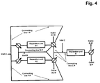
- the apparatus comprises two connecting lines between the fluid outlet of separation unit A1 and the fluid inlet of separation unit A2 and two connecting lines between the fluid outlet of separation unit A2 and the fluid inlet of separation unit A1 (connecting lines F-F and W-F in figure 4 ), thus enabling a fluid communication between the outlet of separation unit A1 and the inlet of separation unit A2 as well as a fluid communication between the outlet of separation unit A2 and the inlet of separation unit A1.
- valves are located close to the inlet and outlet of separation units A1 and A2 and the connecting lines start from these valves.
- At least two buffer reservoirs are in fluid connection with the inlets of separation units A1 and A2.
- One or more valves and/or additional fluid inlets might be located in the connecting line between the buffer reservoirs and the inlets of separation units A1 and A2.
- the apparatus further comprises one or more additional fluid inlets prior to the fluid inlets of separation units A2 and A1, preferably to a connecting line between the fluid outlet of separation unit A2 and the fluid inlet of separation unit A1 and to a connecting line between the fluid outlet of separation unit A1 and the fluid inlet of separation unit A2.
- the apparatus comprises an additional fluid inlet prior to the fluid inlet of column B that means, preferably a connecting line to one or more reservoirs is located prior to the fluid inlet of column B in the connecting line between the outlets of columns A1 and A2 and the inlet of column B.
- the apparatus comprises an additional reservoir with virus inactivation buffer that is at least in fluid connection with the inlet of one of the three separation units.
- the present invention is further directed to a continuous method of purifying a target molecule from one or more impurities in a sample, the method comprising the steps of
- the target molecule is an antibody.
- the sample is continuously loaded alternately to either separation unit A1 or separation unit A2.
- separation units A1 and A2 are run in the bind and elute mode and separation unit B is run in the flow through mode.
- the fluid outlet of separation unit A1 is at least partly in fluid communication with the fluid inlet of separation unit A2 to enable the capture of the starting to leach target molecule from the separation unit A1 to be bound to separation unit A2.
- the fluid outlet of separation unit A2 is preferably at least partly in fluid communication with the fluid inlet of separation unit A1 to enable the capture of the starting to leach target molecule from the separation unit A2 to be bound to separation unit A1.
- separation unit A2 while washing the unbound sample from the separation unit A1, separation unit A2 is at least partly in fluid communication with the reservoir containing sample solution and separation unit A1. That means separation unit A2 is simultaneously loaded with unbound sample that is eluted from unit A1 and with sample solution coming from the reservoir. And while washing the unbound sample from the separation unit A2, separation unit A1 is in fluid communication with the reservoir containing sample solution and separation unit A2.
- separation unit B while separation unit B is in fluid communication with separation unit A1, it is also in fluid communication with a buffer reservoir. And while separation unit B is in fluid communication with separation unit A2, it is also in fluid communication with a buffer reservoir.
- a virus inactivation buffer is pumped through separation units A1 and A2 after loading the units with the target molecule.
- a virus inactivation buffer is pumped through separation unit B after loading the unit with the target molecule.
- the sample subjected to the method of the present invention is a clarified sample. That means prior to loading the sample on separation unit A1 or A2 it is clarified by subjecting it to one or more of the following: centrifugation, filtration and/or settling. In a very preferred embodiment, the sample is treated with a precipitant prior to clarification by centrifugation, filtration and/or settling.
- target molecule refers to any molecule, substance or compound or mixtures thereof that shall be isolated, separated or purified from one or more impurities in a sample.
- the target molecule is a protein or a mixture of two or more proteins.
- the target molecule is an antibody.
- antibody refers to a protein which has the ability to specifically bind to an antigen.
- antibodies are having a basic four-polypeptide chain structure consisting of two heavy and two light chains, said chains being stabilized, for example, by interchain disulfide bonds.
- Antibodies may be monoclonal or polyclonal and may exist in monomeric or polymeric form, for example, IgM antibodies which exist in pentameric form and/or IgA antibodies which exist in monomeric, dimeric or multimeric form.
- Antibodies may also include multispecific antibodies (e.g., bispecific antibodies), and antibody fragments so long as they retain, or are modified to comprise, a ligand-specific binding domain.
- fragment refers to a part or portion of an antibody or antibody chain comprising fewer amino acid residues than an intact or complete antibody or antibody chain. Fragments can be obtained via chemical or enzymatic treatment of an intact or complete antibody or antibody chain. Fragments can also be obtained by recombinant means. When produced recombinantly, fragments may be expressed alone or as part of a larger protein called a fusion protein. Exemplary fragments include Fab, Fab', F(ab')2, Fc and/or Fv fragments. Exemplary fusion proteins include Fc fusion proteins. According to the present invention fusion proteins are also encompassed by the term "antibody".
- an antibody is an Fc region containing protein, e.g., an immunoglobulin.
- an Fc region containing protein is a recombinant protein which includes the Fc region of an immunoglobulin fused to another polypeptide or a fragment thereof.
- Exemplary polypeptides include, e.g., renin; a growth hormone, including human growth hormone and bovine growth hormone; growth hormone releasing factor; parathyroid hormone; thyroid stimulating hormone; lipoproteins; ⁇ -1-antitrypsin; insulin ⁇ -chain; insulin ⁇ -chain; proinsulin; follicle stimulating hormone; calcitonin; luteinizing hormone; glucagon; clotting factors such as factor VIIIC, factor IX, tissue factor, and von Willebrands factor; anti-clotting factors such as Protein C; atrial natriuretic factor; lung surfactant; a plasminogen activator, such as urokinase or human urine or tissue-type plasminogen activator (t-PA); bombesin; thrombin; hemopoietic growth factor; tumor necrosis factor - ⁇ and - ⁇ ; enkephalinase; RANTES (regulated on activation normally T- cell expressed and secreted); human macrophage inflammatory protein (
- sample refers to any composition or mixture that contains a target molecule.
- Samples may be derived from biological or other sources.
- Biological sources include eukaryotic and prokaryotic sources, such as plant and animal cells, tissues and organs.
- the sample may also include diluents, buffers, detergents, and contaminating species, debris and the like that are found mixed with the target molecule.
- the sample may be "partially purified” (i.e., having been subjected to one or more purification steps, such as filtration steps) or may be obtained directly from a host cell or organism producing the target molecule (e.g., the sample may comprise harvested cell culture fluid).
- impurity refers to any foreign or objectionable molecule, including a biological macromolecule such as DNA, RNA, one or more host cell proteins, endotoxins, lipids and one or more additives which may be present in a sample containing the target molecule that is being separated from one or more of the foreign or objectionable molecules using a process of the present invention. Additionally, such impurity may include any reagent which is used in a step which may occur prior to the method of the invention.
- purifying refers to increasing the degree of purity of a target molecule from a composition or sample comprising the target molecule and one or more impurities. Typically, the degree of purity of the target molecule is increased by removing (completely or partially) at least one impurity from the composition.
- flow-through process refers to a product separation technique in which at least one product ⁇ e.g., an Fc region containing protein) contained in a sample along with one or more contaminants is intended to flow through a chromatographic resin or media, while at least one potential contaminant or impurity binds to the chromatographic resin or media.
- the "flow-through mode” is generally an isocratic operation (i.e., a chromatography process during which the composition of the mobile phase is not changed).
- the methods e.g. employ an anion and/or cation exchange chromatography step which is performed in a flow-through mode.
- binding and elute mode and "bind and elute process,” as used interchangeably herein, refer to a product separation technique in which at least one product (target molcecule) contained in a sample (e.g., an Fc region containing protein) binds to a chromatographic resin or media and is subsequently eluted.
- a sample e.g., an Fc region containing protein
- the term "reservoir” as used herein refers to any container, tank or bag, which may be used to store any buffer to be used when performing the method of the invention or the sample or any other liquid that shall be used in the method of the invention. Additionally a “reservoir” is any container, tank or bag that is used to collect the output of a process step (e.g., an eluate from a column).
- inline dilution refers to a buffer exchange step or an in-line solution condition adjustment, which is typically an alternative in many conventional processes, to the use of a holding tank.
- two solutions can be mixed or titrated during transfer using solution blending in a pipe or mixing vessel, filtration device or apparatus.
- a solution may be required to be diluted in order to reduce conductivity by blending the solution with another lower conductivity solution.
- Buffer exchange can be accomplished with the help of filtration devices, such as diafiltration, ultrafiltration and the like.
- the methods provide an improved process for purifying proteins, which eliminates the need for a buffer exchange step.
- chromatography refers to any kind of technique which separates an analyte of interest (e.g. a target molecule) from other molecules present in a mixture.
- analyte of interest e.g. a target molecule
- the target molecule is separated from other molecules as a result of differences in rates at which the individual molecules of the mixture migrate through a stationary medium under the influence of a moving phase, or in bind and elute processes.
- matrix or "chromatography matrix” are used interchangeably herein and refer to any kind of sorbent, resin or solid phase which in a separation process separates a target molecule (e.g., an Fc region containing protein such as an immunoglobulin) from other molecules present in a mixture.
- a target molecule e.g., an Fc region containing protein such as an immunoglobulin
- the target molecule is separated from other molecules as a result of differences in rates at which the individual molecules of the mixture migrate through the matrix under the influence of a moving phase, or in bind and elute processes.
- Non-limiting examples include particulate, monolithic or fibrous resins as well as membranes that can be put in columns or cartriges.
- Examples of materials for forming the matrix include polysaccharides (such as agarose and cellulose); and other mechanically stable matrices such as silica (e.g. controlled pore glass), poly(styrenedivinyl)benzene, polyacrylamide, ceramic particles and derivatives of any of the above.
- Examples for typical matrix types suitable for the method of the present invention are cation exchange resins, affinity resins, anion exchange resins or mixed mode resins.
- a “ligand” is a functional group that is attached to the chromatography matrix and that determines the binding properties of the matrix.
- ligands include, but are not limited to, ion exchange groups, hydrophobic interaction groups, hydrophilic interaction groups, thiophilic interactions groups, metal affinity groups, affinity groups, bioaffinity groups, and mixed mode groups (combinations of the aforementioned).
- Some preferred ligands that can be used herein include, but are not limited to, strong cation exchange groups, such as sulphopropyl, sulfonic acid; strong anion exchange groups, such as trimethylammonium chloride; weak cation exchange groups, such as carboxylic acid; weak anion exchange groups, such as N 5 N diethylamino or DEAE; hydrophobic interaction groups, such as phenyl, butyl, propyl, hexyl; and affinity groups, such as Protein A, Protein G, and Protein L.
- strong cation exchange groups such as sulphopropyl, sulfonic acid
- strong anion exchange groups such as trimethylammonium chloride
- weak cation exchange groups such as carboxylic acid
- weak anion exchange groups such as N 5 N diethylamino or DEAE
- hydrophobic interaction groups such as phenyl, butyl, propyl, hexyl
- affinity groups such as Protein A, Protein G, and Protein
- affinity chromatography refers to a protein separation technique in which a target protein (e.g., an Fc region containing protein of interest or antibody) is specifically bound to a ligand which is specific for the target protein.
- a target protein e.g., an Fc region containing protein of interest or antibody
- a ligand is generally referred to as a biospecific ligand.
- the biospecific ligand e.g., Protein A or a functional variant thereof
- the target protein generally retains its specific binding affinity for the biospecific ligand during the chromatographic steps, while other solutes and/or proteins in the mixture do not bind appreciably or specifically to the ligand.
- Binding of the target protein to the immobilized ligand allows contaminating proteins or protein impurities to be passed through the chromatography matrix while the target protein remains specifically bound to the immobilized ligand on the solid phase material.
- the specifically bound target protein is then removed in active form from the immobilized ligand under suitable conditions (e.g., low pH, high pH, high salt, competing ligand etc.), and passed through the chromatographic column with the elution buffer, free of the contaminating proteins or protein impurities that were earlier allowed to pass through the column.
- suitable conditions e.g., low pH, high pH, high salt, competing ligand etc.
- Any component can be used as a ligand for purifying its respective specific binding protein, e.g. antibody.
- Protein A is used as a ligand for an Fc region containing target protein.
- the conditions for elution from the biospecific ligand (e.g., Protein A) of the target protein (e.g., an Fc region containing protein) can be readily determined by one of ordinary skill in the art.
- Protein G or Protein L or a functional variant thereof may be used as a biospecific ligand.
- a biospecific ligand such as Protein A is used at a pH range of 5-9 for binding to an Fc region containing protein, washing or re-equilibrating the biospecific ligand / target protein conjugate, followed by elution with a buffer having pH about or below 4 which contains at least one salt.
- ion-exchange and “ion-exchange chromatography” refers to the chromatographic process in which a solute or analyte of interest (e.g., an Fc region containing target protein) in a mixture interacts with a charged compound linked (such as by covalent attachment) to a solid phase ion exchange material such that the solute or analyte of interest interacts non-specifically with the charged compound more or less than solute impurities or contaminants in the mixture.
- contaminating solutes in the mixture elute from a column of the ion exchange material faster or slower than the solute of interest or are bound to or excluded from the resin relative to the solute of interest.
- Ion-exchange chromatography specifically includes cation exchange, anion exchange, and mixed mode ion exchange chromatography.
- cation exchange chromatography can bind the target molecule (e.g., an Fc region containing target protein) followed by elution (cation exchange bind and elution chromatography or "CIEX”) or can predominately bind the impurities while the target molecule "flows through” the column (cation exchange flow through chromatography FT-CIEX).
- Anion exchange chromatography can bind the target molecule (e.g., an Fc region containing target protein) followed by elution or can predominately bind the impurities while the target molecule "flows through” the column.
- the anion exchange chromatography step is performed in a flow through mode.
- ion exchange matrix refers to a chromatography matrix that is negatively charged (i.e. a cation exchange resin) or positively charged (i.e. an anion exchange resin).
- the charge may be provided by attaching one or more charged ligands to the matrix, e.g. by covalent linking.
- the charge may be an inherent property of the matrix (e.g. as is the case for silica, which has an overall negative charge).
- a "cation exchange matrix” refers to a chromatography matrix which is negatively charged, and which thus has free cations for exchange with cations in an aqueous solution passed over or through the solid phase.
- a negatively charged ligand attached to the solid phase to form the cation exchange resin may, e.g., be a carboxylate or sulfonate.
- Commercially available cation exchange resins include carboxy-methyl-cellulose, sulphopropyl (SP) immobilized on agarose (e.g., SP-SEPHAROSE FAST FLOWTM or SP-SEPHAROSE HIGH PERFORMANCETM, from Pharmacia) and sulphonyl immobilized on agarose (e.g. S-SEPHAROSE FAST FLOWTM from Pharmacia).
- SP sulphopropyl
- SP sulphopropyl
- S-SEPHAROSE FAST FLOWTM from Pharmacia
- Fractogel® EMD SO 3 is Fractogel® EMD SE
- a “mixed mode” matrix is a chromatography matrix which carries at least two types of functionalities which can interact with the target molecule and/or impurities. Such functionalities can be ion exchange groups, hydrophobic interaction groups, hydrophilic interaction groups, thiophilic interactions groups, metal affinity groups, affinity groups and bioaffinity groups.
- Preferred mixed mode matrices to be used in the present invention are matrices carrying at least anion exchange and cation exchange groups or mixed mode ion exchange matrices.
- Carry at least two types of functionalities means in one embodiment that one type of matrix is provided that is covalently modified with at least two types of different functionalities.
- the mixed mode matrix is made of a combination of two or more different matrices each having at least one functionality, whereby the combination is realized by combining the matrices in one separation unit.
- the mixed mode matrix can be a mixture of two different matrices, each matrix carrying at least one functionality, e.g. be a mixture of a cation exchange matrix and an anion exchange matrix, for example both present in the form of sorbent particles which can be easily mixed in the separation unit. It is also possible to couple one column filled with a first matrix with another column filled with a second matrix to one separation unit so that the sample liquid is flowing through both matrices.
- a “mixed mode ion exchange matrix” refers to a chromatography matrix which is covalently modified with cationic and/or anionic and hydrophobic moieties.
- a commercially available mixed mode ion exchange resin is BAKERBOND ABXTM (J. T. Baker, Phillipsburg, N.J.) containing weak cation exchange groups, a low concentration of anion exchange groups, and hydrophobic ligands attached to a silica gel solid phase support matrix.
- Mixed mode cation exchange matrices typically have cation exchange groups and hydrophobic moieties.
- Suitable mixed mode cation exchange matrices are Capto® MMC (GE Healthcare) and Eshmuno ® HCX (Merck).
- Mixed mode anion exchange matrices typically have anion exchange groups and hydrophobic moieties. Suitable mixed mode anion exchange matrices are Capto ® Adhere (GE Healthcare).
- anion exchange matrix is used herein to refer to a chromatography matrix which is positively charged, e.g. having one or more positively charged ligands, such as quaternary amino groups, attached thereto.
- commercially available anion exchange resins include DEAE cellulose, QAE SEPHADEXTM and FAST Q SEPHAROSETM (Pharmacia).
- Peferred materials are Fractogel® EMD TMAE, Fractogel® EMD TMAE highcap, Eshmuno ® Q and Fractogel® EMD DEAE..
- Protein A and “Prot A” are used interchangeably herein and encompasses Protein A recovered from a native source thereof, Protein A produced synthetically (e.g., by peptide synthesis or by recombinant techniques), and variants thereof which retain the ability to bind proteins which have a CH 2 /CH 3 region, such as an Fc region.
- Protein A can be purchased commercially from Repligen, Pharmacia and Fermatech. Protein A is generally immobilized on a chromatography matrix.
- the term “ProA” also refers to an affinity chromatography matrix or column containing chromatographic solid support matrix to which is covalently attached Protein A.
- An interaction compliant with such value for the binding constant is termed "high affinity binding" in the present context.
- such functional derivative or variant of Protein A comprises at least part of a functional IgG binding domain of wild-type Protein A, selected from the natural domains E, D, A, B, C or engineered mutants thereof which have retained IgG binding functionality.
- Protein A derivatives or variants engineered to allow a single-point attachment may also be used in the affinity chromatography step in the claimed methods.
- Single point attachment generally means that the protein moiety is attached via a single covalent bond to a chromatographic support material of the Protein A affinity chromatography. Such single-point attachment may also occur by use of suitably reactive residues which are placed at an exposed amino acid position, namely in a loop, close to the N- or C-terminus or elsewhere on the outer circumference of the protein fold. Suitable reactive groups are e.g. sulfhydryl or amino functions.
- affinity chromatography matrix is used herein to refer to a chromatography matrix which carries ligands suitable for affinity chromatography.
- the ligands e.g., Protein A or a functional variant thereof
- a proteinA matrix is a proteinA matrix.
- binding refers to the generally reversible binding of the target molecule to a ligand through the combined effects of spatial complementarity of e.g. protein and ligand structures at a binding site coupled with electrostatic forces, hydrogen bonding, hydrophobic forces, and/or van der Waals forces at the binding site.
- spatial complementarity e.g. protein and ligand structures at a binding site coupled with electrostatic forces, hydrogen bonding, hydrophobic forces, and/or van der Waals forces at the binding site.
- Non-limiting examples of specific binding includes antibody-antigen binding, enzyme- substrate binding, enzyme-cofactor binding, metal ion chelation, DNA binding protein-DNA binding, regulatory protein-protein interactions, and the like. Ideally, in affinity chromatography specific binding occurs with an affinity of about 10 "4 to 10 "8 M in free solution.
- detergent refers to ionic and nonionic surfactants such as polysorbates (e.g. polysorbates 20 or 80); poloxamers (e.g. poloxamer 188); Triton; sodium dodecyl sulfate (SDS); sodium laurel sulfate; sodium octyl glycoside; lauryl-, myristyl-, linoleyl-, or stearyl-sulfobetaine; lauryl-, myristyl-, linoleyl- or stearyl-sarcosine; linoleyl-, myristyl-, or cetyl-betaine; lauroamidopropyl-, cocamidopropyl-, linoleamidopropyl-, myristamidopropyl-, palmidopropyl-, or isostearamidopropyl-betaine (e.g.
- Useful detergents is a polysorbate, such as polysorbate 20 (TWEEN 20®.) or polysorbate 80 (TWEEN 80®.) or various acids, such as octanoic acid.
- a “buffer” is a solution that resists changes in pH by the action of its acid-base conjugate components.
- Various buffers which can be employed depending, for example, on the desired pH of the buffer are described in Buffers.
- Non- limiting examples of buffers include MES, MOPS, MOPSO, Tris, HEPES, phosphate, acetate, citrate, succinate, and ammonium buffers, as well as combinations of these.
- buffer or “solvent” is used for any liquid composition that is used to load, wash, elute and reequilibrate the separation units.
- a buffer is used to load the sample or composition comprising the target molecule (e.g., an Fc region containing target protein) and one or more impurities onto a chromatography column (e.g., an affinity column or an ion exchange column).
- the buffer has a conductivity and/or pH such that the target molecule is bound to the chromatography matrix while ideally all the impurities are not bound and flow through the column.
- a buffer When “loading" a separation column to "flow through” a target molecule a buffer is used to load the sample or composition comprising the target molecule (e.g., an Fc region containing target protein) and one or more impurities onto a chromatography column (e.g., an affinity column or an ion exchange column).
- the buffer has a conductivity and/or pH such that the target molecule is not bound to the chromatography matrix and flow through to column while ideally all the impurities are bound the column.
- reequilibrating refers to the use of a buffer to re-equilibrate the chromatography matrix prior to loading the target molecule.
- the loading buffer is used for reequilibrating.
- washing a chromatography matrix is meant passing an appropriate buffer through or over the matrix. Typically washing is used to remove weakly bound contaminants from the matrix prior to eluting the target molecule.
- the wash buffer and the loading buffer are be the same.
- virus inactivation buffer it is used to inactivate certain present virus prior to eluting the target molecule.
- the virus inactivation buffer differs from loading buffer since it may contain detergent/detergents or have different properties (pH/conductivity/salts and their amounts).
- a molecule e.g., a polypeptide of interest or an impurity
- a chromatography matrix is meant to remove the molecule therefrom by altering the solution conditions such that buffer competes with the molecule of interest for the ligand sites on the chromatography resin.
- a non-limiting example is to elute a molecule from an ion exchange resin by altering the ionic strength of the buffer surrounding the ion exchange material such that the buffer competes with the molecule for the charged sites on the ion exchange material.
- virus inactivation refers to any process which may render a virus incapable of infecting a cell or inhibit a virus function through a physico-chemical means.
- Typical virus inactivation methods include, but are not limited to, low pH treatment (e.g., below pH 4.5, below 4.0 or below 3.8), heat treatment, treatment with surfactants and radiation (e.g., ultraviolet light exposure).
- virus inactivation methods are directed against retroviruses.
- low pH conditions are used for virus inactivation as such conditions typically disrupt the virus lipid envelope, thereby inactivating the virus.
- certain surfactants are used for virus inactivation as they typically disrupt the virus, thereby inactivating the virus (like Tween, Triton X-100, SDS).
- a "separation unit” is an equipment onto which a chromatographic separation step can be performed.
- a separation unit typically is a chromatography column or chromatography cartridge which is filled with a sorbent matrix.
- Chromatography columns are known to a person skilled in the art. They typically comprise a column tube with end-fittings for fluid-inlet and fluid-outlet. The column tube is filled with a suitable chromatography matrix.
- a "continuous" process is a process that is not run in the batch mode.
- new sample is loaded onto separation units A1 or A2 not only once but sequentially in an alternating way either on separation unit A1 or on separation unit A2 with only short breaks or preferably no breaks in between.
- a "connecting line” is any tube, hose, pipe or channel which is suitable for flowing liquids there through.
- a connecting line can be interrupted by one or more valves.
- a connecting line might be straight or branched.
- two parts of an apparatus are "in fluid connection” it means that there is a connecting line between the two parts of the apparatus so that liquid can flow from one part to the other.
- This connecting line can be direct or it can be interrupted by one or more valves, by a separation unit or other parts of the apparatus.
- the term "in fluid connection” encompasses a fluid connection that is permanent but it also encompasses a fluid connection that is not permanent and is made of a connecting line that is e.g.
- fluid communication describes the status in which a "fluid connection" is actually used by flowing liquid through the connecting line. If two parts of the system are partly in fluid communication it means that the fluid communication is not permanent and the liquid is not permanently flowing from one part to the other but only part of the time. Typically the flow of the liquid between two parts of the system is started and/or stopped with the aid of valves that direct the liquid flow.
- a "fluid inlet” or “inlet” is any means that enables the introduction of liquid.
- a separation unit inlet is for example the end-fitting of a chromatography column to which a connecting line can be connected.
- An inlet can also be a valve that provides the introduction of liquid in a connecting line.
- a inlet can also be the end of a connecting line.
- An "outlet” or “fluid outlet” is any means that enables the withdraw of a liquid.
- a separation unit outlet is for example the end-fitting of a chromatography column to which a connecting line can be connected.
- An outlet can also be a valve that provides the introduction of liquid in a connecting line.
- a outlet can also be the end of a connecting line.
- a "fluid selection valve” is any means that enables a fluid communication selectively between any connected fluid and the system part.
- a fluid selection valve is for example the valve prior the separation unit inlet, to which the connecting lines can be connected and selectively chosen which can enable the fluid communication between the selected line and the separation unit inlet.
- a fluid selection valve is for example the valve after the separation unit outlet, to which the connecting lines can be connected and selectively chosen which can enable the fluid communication between the selected line and the separation unit outlet.
- a fluid selection valve can also be a valve that provides the introduction of liquid in a connecting line.
- a fluid selection valve can also be the end of a connecting line.
- a “solvent selection valve” is a fluid selection valve that enables a fluid communication selectively between any connected solvent reservoir and the system part.
- a solvent selection valve is for example the valve prior the solvent pump, to which the connecting lines can be connected from the solvent reservoirs and selectively chosen which can enable the fluid communication between the selected solvent and the pump.
- a "fluid selection valve” and “solvent selection valve” can be of identical type or of different type.
- a solvent delivery system is a system that enable the delivery of liquid.
- the solvent delivery system of an apparatus comprises at least one reservoir and at least one pump to transport the liquid from the reservoir to another part of the apparatus which is in liquid connection with the reservoir. It is known to a person skilled in the art that every time liquid is transferred from a reservoir to a separation unit this is done with the aid of a pump.
- the pumps can also be used to mix two or more liquid streams coming from two or more reservoirs.
- the present invention for the first time provides a method and an apparatus suitable for a continuous chromatography process which only needs three separation columns.
- the process is a two step procedure comprising two chromatographic steps. If the apparatus has three separation units, the first chromatographic step (capture) is performed alternating and sequentially on two separation units, the second chromatographic step (polishing) is performed, also sequentially, on the third separation unit.
- the first two separation units having the same chromatography matrix are alternately loaded with the sample. That means while one of the units is loaded with the sample, at the same time, the other unit can be subjected to other process steps like equilibration, washing, elution of the target molecule etc.
- the third separation unit which has a chromatography matrix that is different from the matrix of the first two units is fed with the target molecule that is eluted from the first two units.
- the first two units are loaded sequentially, they are also eluted sequentially. That means while one unit is loaded, the other - already loaded - unit is optionally washed and then the target molecule is eluted from this unit with an elution buffer that preferably allows direct feed to the third unit.
- the purified target molecule can then be recovered from the fluid outlet of the third unit.
- the method and apparatus according to the present invention allow high loading of the first dimension separation units resulting in high dynamic binding capacities and faster throughput to shorten residence times.
- the method and apparatus according to the present invention enable connecting the first separation dimension (capture) with the second separation dimension (polishing) typically without additional conditioning, since the captured product is preferably eluted from the first dimension in the conditions, that fit the second (polishing) dimension.
- the method according to the present invention can be applied to different chromatographic modes, e.g. CIEX capture combined with AIEX polishing, Prot A capture combined with CIEX polishing and AIEX capture combined with CIEX polishing, without changes in the concept and technological solution. Therefore it is not only economical, but also a robust purification technology suitable for the purification of a wide range of target molecules (e.g. biopharmaceutical molecules having pl from 2-14).
- target molecules e.g. biopharmaceutical molecules having pl from 2-14.
- the separation units A1 and A2 have an affinity chromatography matrix and the separation unit B has a cation exchange chromatography matrix.
- the separation units A1 and A2 have an affinity chromatography matrix and the separation unit B has an anion exchange chromatography matrix.
- the separation units A1 and A2 have a cation exchange chromatography matrix and the separation unit B has an anion exchange chromatography matrix.
- the separation units A1 and A2 have an anion exchange chromatography matrix and separation unit B has a cation exchange chromatography matrix.
- the separation units A1 and A2 have an affinity chromatography matrix and separation unit B has a mixed mode chromatography matrix.
- the separation units A1 and A2 have an affinity chromatography matrix and separation unit B has a mixed mode cation and an anion exchange chromatography matrix or a mixed mode anion and a cation exchange chromatography matrix or a mixed mode cation and a mixed mode anion exchange chromatography matrix.
- the separation units A1 and A2 have a cation exchange matrix and a separation unit B has a mixed mode chromatography matrix.
- FIG. 2 A schematic view of the apparatus according to the invention is shown in figure 2 .
- the connecting line between the outlets of separation untis A1 and A2 and the inlet of separation unit B is named connecting line C-P.
- the apparatus according to the invention comprises three separation units, two capture separation units A1 and A2 having the same chromatography matrix and one polishing separation unit B. Beside the separation units it typically comprises at least two pumps, one or more valves, liquid connections, and reservoirs. It may additionally comprise filter units, detection units or other equipment that may be needed or suitable in a chromatographic separation procedure.
- the apparatus according to the present invention can be a conventional chromatography system or a single-use system. It comprises columns, valves, reservoirs and other equipment that is typically used in chromatography systems.
- the separation units might for example be stainless steel columns, plastic columns or glass columns that are filled with the respective chromatography matrices and have suitable end-fittings for solvent inlet and outlet.
- the apparatus according to the present invention may comprise more than three separation units, for example it might have 3 or 4 capture separation units having the same chromatography matrix and 2 or 3 polishing separation units having the same chromatography matrix but a chromatography matrix that differs from the matrix of the capture separation units. In exemplary embodiments it may have
- the apparatus according to the present invention has five separation units, three capture separation units A1, A2 and A3 having the same chromatography matrix and two polishing separation units B1 and B2.
- the apparatus also comprises at least two buffer reservoirs and at least two pumps, also called the solvent delivery system, which provide for the storage and provision of the buffers needed e.g. for the loading, washing and the elution of the target molecules.
- separation units A1, A2 and A3 have at least one fluid inlet that is connected to at least one buffer reservoir and separation units B1 and B2 have at least one fluid inlet that is connected to at least one buffer reservoir.
- separation units B1 and B2 have at least one fluid outlet.
- the apparatus according to the present invention has three separation units, two capture separation units A1 and A2 having the same chromatography matrix and one polishing separation unit B.
- At least one valve is located between the fluid outlets of separation units A1 and A2 and the fluid inlet of separation unit B.
- the apparatus also comprises at least two buffer reservoirs and at least two pumps, also called the solvent delivery system, which provide for the storage and provision of the buffers needed e.g. for the loading, washing and the elution of the target molecules. Typically for each chromatographic step, one loading buffer and one elution buffer is needed.
- the apparatus only comprises two buffer reservoirs for binding and elution buffers, one reservoirs for buffer A and one reservoir for buffer B.
- Buffer A is a loading and thus binding buffer for the first dimension providing conditions under which the target molecule is captured on the separation units A1/A2.
- buffer A is an elution buffer for the second dimension providing conditions under which the target molecule is eluted from separation unit B.
- Buffer B is a elution buffer for the first dimension (separation unit A1/A2), but a binding buffer for the second dimension (separation unit B).
- the apparatus can comprise additional reservoirs for other buffers, cleaning in place, virus inactivation etc.
- the reservoirs and the separation units are connected via connecting lines, valves and pumps.
- the preferred solvent selection valves for the choice of the solvent prior pump are valves having 6 solvent inlets and 1 solvent outlet which can be connected directly to pump. Any pumps which assure solvent flow could be used including peristaltic pumps, isocratic pumps, gradient pumps, high pressure pumps and the like, low pressure pumps and the like.
- the preferred fluid selection valves for the choice of the fluid introduction prior a system part inlet are valves having 6 fluid inlets and 1 outlet which can be connected to the system part inlet.
- the preferred fluid selection valves for the choice of the fluid withdraw after the system part outlet are valves having 6 fluid outlets and 1 inlet which can be connected to the system part outlet.
- the apparatus additionally comprises connecting lines between the two capture separation units A1 and A2 that enable liquid connection between the outlet of column A1 and the inlet of column A2 and vice versa.
- a schematic view of this embodiment is shown in Figure 3 , where the additional connecting lines are named connecting line F-F.
- This setup enables a capture of the leached product from the first capture separation unit (at the end of loading) on the second separation unit (just reequilibrated and ready for capture). This enables to use higher throughputs and binding capacities without the loss of target molecule.
- a solvent delivery system is connected to the connecting lines between the two capture separation units A1 and A2, preferably sample solvent delivery system in order to assure a continuous sample feed to any selected capture separation unit.
- the apparatus further comprises one or more detectors.
- the detectors can be used for control of sample transfer between the columns, for the analysis of sample quality, monitoring etc.
- the detectors can be located wherever suitable, typically they are located prior to the fluid inlet and/or after the fluid outlet of the separation columns.
- Suitable detectors are pH detectors, UV detectors, infrared detectors or detectors measuring conductivity.
- detectors are located prior to the fluid inlet and after the fluid outlet of all separation columns. This set up ensures the control of the sample transfer between the separation units.
- the apparatus further comprises a computer system.
- the detectors as well as the pumps and valves are connected to the computer system.
- This computer system enables control of the pumps and valves and detectors.
- the computer system comprises a software and algorithms that allow the apparatus to be used in a partly or fully automated mode.
- an additional fluid inlet that means preferably a connecting line to one or more reservoirs is located prior to the fluid inlet of separation unit B.
- this additional inlet is named Inlet C.
- the additional fluid inlet is located after the outlet of the separation unit A1 and A2 and prior to the fluid inlet of separation unit B.
- it is located after the valve that is located in the connecting line between the outlets of separation unit A1 and A2 and the fluid inlet of separation unit B and prior to the fluid inlet of separation unit B.
- the apparatus further comprises an additional reservoir for cleaning in place.
- Cleaning in place is a technology known to the person skilled in the art. Cleaning in place is the removal of very tightly bound, precipitated or denatured substances from the chromatography matrix. If such contaminants are not removed from the chromatography matrix they might affect the chromatographic properties of the column, decreasing binding capacity and come off in subsequent runs which results in carryover of contaminants or product between cycles.
- a standard CIP protocols typically includes one to five washes with one to three column volumes of aqueous buffers comprising ingredients like
- Concentration of the ingredients like NaOH, the contact time of the CIP buffer on the column as well as the frequency of performing the CIP can be adjusted and determined by the person skilled in the art.
- the apparatus according to the present invention preferably has at least one reservoir containing a CIP buffer.
- the CIP buffer can be used for the CIP of all separation units if suitable. Then the buffer reservoir is in liquid connection with all separation units in a way that the flow of the CIP buffer can be directed to each of the columns independently.
- the apparatus comprises two reservoirs with two different CIP buffers. One reservoir is in fluid connection to the separation units A1 and A2, whereby the flow to separation unit A1 and separation unit A2 can be realized independently, the other reservoir is in fluid connection with separation unit B. Cleaning in place washes can be performed after each separation cycle.
- CIP is done after every second, third, fourth, fifth, sixth, seventh, eighth, ninth or tenth separation cycle depending on the sample and thus the amount and type of contaminants that might contaminate the separation unit.
- a person skilled in the art is aware of the fact that CIP can be left out or can be dramatically simplified for single use systems.
- the apparatus comprises an additional reservoir for virus inactivation (VI).
- V virus inactivation
- Impurity purification, especially virus deactivation and removal are playing the major role in the biopharmaceutical compound production as virus levels in biopharmaceutical compounds are regulated by the FDA. It is possible to perform virus inactivation in an additional purification step, where, depending on the biopharmaceutical compound, virus inactivation can be done e.g. by solvent/detergent inactivation, pasteurization, acidic pH inactivation or UV inactivation.
- the separation units A1 and A2 or separation unit B or all separation units are in fluid connection with an additional reservoir which contains a virus inactivation buffer.
- the virus inactivation buffer is then flowed through the separation unit on which the virus inactivation shall take place while the target molecule is bound on the matrix of said separation unit.
- the separation units are connected with the reservoir for either low pH or detergent virus inactivation or both, preferably the virus inactivation step is done on cation exchange matrixes.
- Suitable buffers for integrated low pH virus inactivation are buffers with an acidic pH, preferably buffers with a pH between 3 and 4. Examples of suitable buffers are acetate, glycine and others.
- Suitable buffers for integrated surfactant virus inactivation are buffers with at least one surfactant or detergent.
- Suitable detergents are octanoic acid, Tween or Triton surfactant X-100.
- the apparatus does not contain any reservoir for pooling.
- known chromatographic separation procedures often all fractions that are eluted from a first column and that contain the target molecule are first pooled before they are loaded on a second chromatography column. It has been found that the method and apparatus of the present invention provide a set up in which such pooling is not necessary.
- the target molecule is eluted from the separation units A1 or A2
- all eluent containing the target molecule is directly, without pooling directed to the inlet of separation unit B and loaded on separation unit B. This additionally speeds up the purification process.
- the separation units A1 and A2 are in fluid connection with separation unit B without any reservoir interrupting this connection.
- the apparatus only comprises two buffer reservoirs for binding and elution as described above. If the separation mode necessitates the use of more than two buffers, a pooling can also be avoided by introducing an additional fluid inlet prior to the fluid inlet of separation unit B (as described above) which can be used for inline dilution and buffer exchange.
- the apparatus comprises two separation units with an affinity chromatography matrix and one separation unit with an ion exchange, preferably a cation exchange matrix.
- Suitable affinity matrices are matrices having Protein A, Protein G, Protein L or Protein r functional groups (e.g. Prosep® Highcap (Merck Millipore), Prosep® Ultra Plus (Merck Millipore), Poros® Prot A(Life Technologies), A650F (Tosoh), MabSelect® Sure (GE).
- Suitable cation exchange matrices are matrices having but not limited to strong cation exchange groups, such as sulphopropyl, sulfonic acid (Fractogel EMD ®SO 3 , Fractogel EMD ® SE highcap (Merck) Eshmuno® S (Merck) SP-SEPHAROSE FAST FLOWTM or SP-SEPHAROSE HIGH PERFORMANCETM, from Pharmacia, or but not limited to weak cation exchange groups, such as carboxylic acid like Fractogel ® EMD Carboxy (Merck).
- strong cation exchange groups such as sulphopropyl, sulfonic acid (Fractogel EMD ®SO 3 , Fractogel EMD ® SE highcap (Merck) Eshmuno® S (Merck) SP-SEPHAROSE FAST FLOWTM or SP-SEPHAROSE HIGH PERFORMANCETM, from Pharmacia, or but not limited to weak cation exchange groups, such as carboxylic
- the apparatus comprises two separation units with a cation exchange matrix and one separation unit with an anion exchange, matrix.
- Suitable cation exchange matrices are matrices having but not limited to strong cation exchange groups, such as sulphopropyl, sulfonic acid or having but not limited to weak cation exchange groups, such as carboxylic acid are the ones mentioned above.
- Suitable anion exchange matrices are matrices having but not limited to one or more positively charged ligands, such as quaternary amino groups.
- anion exchange resins include DEAE cellulose, QAE SEPHADEXTM and FAST Q SEPHAROSETM (Pharmacia), Fractogel® TMAE (M), Fractogel® TMAE HC (M) or Eshmuno® Q (Merck).
- the apparatus comprises two separation units with an anion exchange matrix and one separation unit with a cation exchange, matrix.
- Suitable cation exchange matrices and anion exchange matrices have been listed above.
- mixed mode matrices can be used instead of ion exchange matrices as well as combinations thereof.
- An example is a combination of anion exchange and a hydrophobic functionality (Capto Adhere (GE Healthcare) or a combination of cation exchange and a hydrophobic functionality such as (captor TM MMC (GE Healthcare), Eshmuno® HCX (Merck KGaA), POROS®XS (Applied Biosystems).
- Figure 1 shows a preferred embodiment of the apparatus according to the present invention.
- Column A1 and A2 are called “CIEX”, showing that these two columns have the same chromatography matrix, e.g. a cation exchange resin.
- Column B is called AIEX, suggesting that this column might have an anion exchange chromatography matrix.
- Conductivity detectors (“Cond.”) are located prior to the fluid inlet of all three columns.
- UV and pH detectors (“UV, pH”) are located at the fluid outlets of all three columns.
- Columns A1 and A2 are connected with 6 reservoirs for cleaning in place (“CIP”), virus inactivation ("VI”), loading buffer (“E.A”), elution buffer (“E.B”), a dilution buffer (“Dil.”) and the sample feed (“Feed”).
- Column B is connected to three reservoirs for cleaning in place (“CIP"), loading buffer (“E.A”), elution buffer (“E.B”).
- CIP cleaning in place
- E.A loading buffer
- E.B elution buffer
- the elution buffer used for columns A1/A2 is the same as the loading buffer used for column B and vice versa.
- the reservoirs and the columns are connected via connecting lines.
- all connecting lines are at least once interrupted by a valve to be able to control the liquid flow. Liquid transport is realized with the aid of pumps.
- the invention further provides a method for continuous purification of a target molecule from a sample comprising the target molecule and one or more impurities.
- the method of the invention is performed on the respective inventive apparatus.
- a schematic view of a suitable apparatus is shown in Figures 2 , 3 and 4 .
- the method comprises sequentially repeating steps.
- separation units A1 and A2 for the first chromatographic dimension are continuously, sequentially loaded with the sample so that while the sample is loaded onto separation unit A1, separation unit A2 is at least partly in fluid communication with separation unit B so that the target molecule is eluted onto separation unit B and separation unit A2 is reequilibrated and while the sample is loaded on separation unit A2, separation unit A1 is at least partly in fluid communication with separation unit B so that the target molecule is eluted onto separation unit B and separation unit A1 is reequilibrated.
- a second chromatography step takes place on separation unit B leading to the recovery of the purified target molecule from the fluid outlet of separation unit B.
- the speed of the two chromatographic separation steps needs to be adjusted.
- loading, chromatographic separation and reequilibration on separation unit B in the second chromatographic step are faster than loading, chromatographic separation and reequilibration on separation units A1 and A2 so that separation unit B is ready for new loading each time the target molecule is eluted either from separation unit A1 or separation unit A2. Otherwise the elution of the target molecules from separation units A1 or A2 is delayed until separation unit B is ready for loading or a second separation unit B2 might be integrated into the system.
- eluting the target molecule from separation units A1/A2 to separation unit B means that the whole fraction containing the target molecule can be loaded on separation unit B or only parts of the fraction. To reduce the amount of impurities it can be advisable to load only those parts of the fraction containing the target molecule on separation unit B which contain very little impurities. It is also possible to take away a part of the target molecule fraction for in process control to analyze the purity and other properties of the target molecule after the first separation step.
- the labelling of the components of the apparatus refers to the labelling used in figure 2 .
- a second chromatography step in the flow through mode takes place on separation column B leading to the recovery of the purified target molecule from the fluid outlet of separation column B.
- the elution conditions of the bind-and elute chromatographic separation step need to be adjusted to the loading conditions for the flow-through step performed on column B.
- an inlet C might be used.
- constant solution properties such as pH and conductivity, are necessary. This is done while conditioning the target molecule eluting from separation units A1 or A2 via Inlet C e.g. by inline dilution or buffer exchange..
- the biopharmaceutical product purification involves separation of the target molecule from very like ones impurities and sensitive separation methods are required, such as weak ion exchange chromatography.
- weak ion exchange chromatography With the method of the present invention, one can do an affinity separation in the bind elute mode, and anion exchange chromatography in weak binding or non-binding conditions (flow through) for the target protein. This was shown to be a very powerful tool. Especially the combination of several matrixes for this flow.through polishing enables to reach required product purity via adsorbing impurities by several different functionalities, such as cation exchange or anion exchange or hydrophobic functionalities and mixtures thereof.
- the method according to the invention is performed by
- the steps a) and b) are repeated at least twice.
- the outlet of separation unit A2 is connected with the inlet of separation unit A1 through a connecting line F-F to enable the capture of the starting to leach target molecule from the separation unit A2 to be bound to separation unit A1 (see figure 3 ).
- separation unit A2 e.g. cation exchange material or affinity material
- inlet B e.g. solvent delivery system
- target molecule e.g. antibody
- the outlet of separation unit A2 is connected with the inlet of separation unit A1 through a connecting line F-F to enable the capture of the starting to leach target molecule from the separation unit A2 to be bound to separation unit A1 (see figure 3 ).
- the sample feed is switched from separation unit A2 to separation unit A1. Meanwhile the target molecule on A1 is washed and eluted onto separation unit B. After reequlibration of separation unit A1 its inlet is connected to the outlet of separation column A2 to ensure that the starting to leach target molecule from the separation unit A1 is bound to separation unit A2.
- This specific intermediate connection of the two separation unit A1 and A2 provides the unique possibility to safe time by loading separation units A1 and A2 with very high amount of target molecule.
- the columns are loaded until about 60 to 80% dynamic binding capacity.
- the apparatus and method according to the present invention offer the possibility to load the separation units A1 and A2 until more than 80% dynamic binding capacity, preferably until 80 to 95% dynamic binding capacity.
- FIG. 3 A schematic view of an apparatus suitable for this embodiment is shown in figure 3 .
- the method of the invention can for example be performed as follows:
- the steps a) to d) are repeated at least twice.
- the separation unit A2 e.g. cation exchange material or affinity material
- inlet B e.g. solvent delivery system
- target molecule e.g. antibody
- the outlet of separation unit A2 is connected with the inlet of separation unit A1 through a connecting line W-F to enable the capture of the washed target molecule from the separation unit A2 to be bound to separation unit A1 (see figure 4 ).
- connection is interrupted and the column A2 outlet is switched to outlet position A2-W to withdraw the unbound molecules.
- the target molecule is further loaded on separation unit A1, as the target molecule on separation unit A2 is further washed and eluted onto separation unit B.
- After reequlibration of separation unit A2 its inlet is connected to the outlet of separation column A1 to ensure that the starting to leach target molecule from the separation unit A1 is bound to separation unit A2.
- This specific intermediate connection of the two separation units A1 and A2 provides the unique possibility to safe time and avoid target molecule losses by washing them.
- the column wash fraction is withdrawn to waste or collected back to the feed reservoir.
- the apparatus and method according to the present invention offer the possibility to wash the separation units A1 and A2 with low target molecule losses, preferably until 2 to 3% of total target molecule losses in preferred purification process.
- FIG. 4 A schematic view of an apparatus suitable for this embodiment is shown in figure 4 .
- the method of the invention can for example be performed as follows:
- the steps a) to f) are repeated at least twice.
- buffers which provide for pH dependent binding and elution. It has been found that especially the elution of the target molecules from separation units A1 and A2 is more efficient and faster when using an elution buffer with a pH that differs from the pH of the loading buffer. In other words, the elution profile is more favourable when using an elution buffer with a pH that differs from the pH of the loading buffer. Elution by a pH gradient is especially preferred.
- Suitable buffers for pH dependent binding and elution are known to a person skilled in the art. Examples of suitable buffer combinations are PBS-glycine, acetate-TRIS and etc.
- the method of the invention comprises the use of only two loading and elution buffers, Buffer A and Buffer B, so that Buffer A is a loading buffer for the first dimension providing conditions under which the target molecule is captured on the separation column A1/A2.
- buffer A is an elution buffer for the second dimension providing conditions under which the target molecule is eluted from separation column B.
- Buffer B is a elution buffer for the first dimension (column A1/A2), but a capture buffer for the second dimension (column B).
- the binding buffer typically has a pH between 6 and 8 and a salt concentration (typical salts are phosphate, acetate, chloride, etc.) between 10 mM and 2 M.
- a salt concentration typically salts are phosphate, acetate, chloride, etc.
- the elution buffer typically has a pH between 2 and 5 and a salt concentration (typical salts are glycine, acetate, etc) between 20mM and 200mM.
- the elution buffer has a pH of 4 this buffer which is suitable for eluting the target molecule from the Prot A matrix of separation unit A1 and A2 is also suitable for loading the target molecules on a separation unit B with a cation exchange matrix.
- the binding the binding buffer typically has a pH between 4 and 7 and a salt concentration (typical salts are phosphate, acetate, NaCl, etc.) between 10mM and 300mM.
- a salt concentration typically salts are phosphate, acetate, NaCl, etc.
- the elution buffer typically has a pH between 7 and 10 and a salt concentration (typical salts are TRIS, PBS, NaCl) between 10mM and 300mM.
- the elution buffer has a pH of 8.5 this buffer which is suitable for eluting the target molecule from the cation exchange matrix of separation unit A1 and A2 is also suitable for loading the target molecules on a separation unit B with an anion exchange matrix.
- the binding buffer typically has a pH between 7 and 10 and a salt concentration (typical salts are TRIS, PBS, NaCl) between 10mM and 300mM.
- a salt concentration typically salts are TRIS, PBS, NaCl
- the elution buffer typically has a pH between 4 and 7 and a salt concentration (typical salts are PBS, acetate, NaCl, etc.) between 10mM and 100mM.
- the elution buffer has a pH of 5.5 this buffer which is suitable for eluting the target molecule from the anion exchange matrix of separation unit A1 and A2 is also suitable for loading the target molecules on a separation unit B with a cation exchange matrix.
- the sample that is subjected to the method of the present invention is a clarified sample. That means the sample is subjected to a clarification step prior to loading it onto separation units A1 or A2.
- the clarification step is intended to separate one or more soluble and/or insoluble impurities from the target molecule.
- insoluble impurities like cells and cellular debris are removed from the sample resulting in a clarified fluid containing the target molecule in solution as well as other soluble impurities.
- a clarification step may involve one or more of the following, either alone or in any combination, centrifugation, settling and/or filtration, preferably tangential flow filtration or depth filtration.
- the clarification step does not involve centrifugation but only filtration and/or settling.
- filtration is depth filtration.
- depth filters are used to remove one or more insoluble impurities.
- Depth filters are filters that use a porous filtration medium to retain particles throughout the medium, rather that just on the surface of the medium.
- a common class of such depth filters are those that comprise a random matrix of fibers bonded (or otherwise fixed), to form a complex, tortuous maze of flow channels. Particle separation in these filters generally results from entrapment by or adsorption to, the fiber matrix.
- the most frequently used depth filter media for bioprocessing of cell culture broths and other feedstocks usually consists of cellulose fibers, a filter aid such as DE (diatomaceous earth), and a positively charged resin binder.
- the porous depth filter is anisotropic.
- the pores have a nominal pore size rating > about 25 ⁇ m.
- the depth filter comprises at least 2 graded layers of non-woven fibers, wherein the graded layers have a total thickness of about 0.3 cm to about 3 cm.
- depth filters comprise a composite of graded layers of non-woven fibers, cellulose, and diatomaceous earth.
- the non-woven fibers comprise polypropylene, polyethylene, polyester, nylon or mixtures thereof.
- Exemplary depth filters may be found in U.S. Provisional Patent Application No. 61/571994 , incorporated by reference herein.
- a centrifugation and/or tangential flow filtration step may be performed prior to a depth filtration step.
- a depth filtration step may be performed without the need for a centrifugation and/or a tangential flow filtration step.
- the sample prior to clarification by centrifugation and/or filtration and/or settling, is pretreated with a precipitation composition to precipitate and remove unwanted contaminants from the sample.
- the precipitation composition at least comprises a precipitant that is able to precipitate contaminants like HCP's, DNA, hormones, etc. from the sample.
- Precipitants cause the precipitation of a compound from an aqueous and/or soluble state to a non-aqueous and/or insoluble state or aggregate and agglutinate fine particles from a solution, resulting in their settling from the liquid phase and a reduction in solution turbidity.
- Suitable precipitants are organic acids (e.g. octanoic acid), inorganic acids (e.g. HCl), other acidic agents that substantially lower the pH towards acidic, salts (e.g., sodium benzoate, sodium chalate, sodium deoxychalate, etc.) other monovalent salts or organic acids which precipitates in the acidic medium).
- organic acids e.g. octanoic acid
- inorganic acids e.g. HCl
- salts e.g., sodium benzoate, sodium chalate, sodium deoxychalate, etc.
- Another example of a precipitant is a short-chain fatty acid such as caprylic acid. In mildly acidic conditions, the addition of short-chain fatty acids such as caprylic acid typically precipitates non IgG proteins while IgG is not precipitated.
- Suitable precipitants are polyelectrolyte polymers (see, e.g., International PCT Patent Application No. WO2008/091740 , incorporated by reference herein).
- stimulus responsive polymers are used for precipitating one or more impurities.
- stimulus responsive polymers can be found, e.g., in U.S. Publication Nos., 20080255027 , 20090036651 , 20090232737 and 20110020327 , incorporated by reference herein.
- Stimulus responsive polymers are generally soluble in an aqueous based solvent under a certain set of process conditions such as pH, temperature and/or salt concentration and are rendered insoluble upon a change in one or more of such conditions and subsequently precipitate out.
- Exemplary stimulus responsive polymers include, but are not limited to, polyallylamine, polyallylamine modified with a benzyl group or polyvinylamine and polyvinylamine modified with a benzyl group, where the stimulus is phosphate or citrate.
- the precipitation composition may further comprise a detergent (Triton X-100, triton X-114, NP-40, Tween-20, OTD, SDS, CHAPS, and/or polyethyleneglycole (PEG) (PEG-1000, PEG 10000) and/or polyvinyl alcohol and/or polyelectrolytes.
- a detergent Triton X-100, triton X-114, NP-40, Tween-20, OTD, SDS, CHAPS, and/or polyethyleneglycole (PEG) (PEG-1000, PEG 10000) and/or polyvinyl alcohol and/or polyelectrolytes.
- the precipitated contaminants are then removed from the sample by clarification prior to loading the sample onto the separation units.
- precipitation is followed by depth filtration, without a centrifugation step to provide the clarified sample.
- the clarification of the sample is performed concurrently with the chromatographic purification according to the method of the present invention for at least a part of its duration.
- the liquid sample containing the target molecule is not stored in a pool tank after clarification to wait for the whole sample volume to be clarified but as soon as clarified sample is resulting from the clarification process it is continuously used as sample solution for the method of the present invention and loaded on separation unit A1 or A2.
- the method of the present invention also when using a clarified sample solution does not require the use of pool tanks which are able to store the whole volume of the sample solution.
- one or more additional flow through purification steps might be performed after performing the second chromatographic step on separation unit B.
- the outlet of separation unit B is in fluid connection with one or more additional separations units.
- One or more valves might be located between the outlet of separation unit B and the inlet of the first additional separation unit and/or in the connecting lines between the optionally following additional separation units (typically connected in series) to ensure the possibility of inline dilution and/or buffer exchange.
- the matrices of the additional flow through devices are typically selected from
- the purified target molecule resulting from the method according to the present invention can be further subjected to additional process steps like formulation/sterilization/concentration steps, where the target molecule containing solution is sterilized and formulated to be in a desired buffer at a desired concentration.
- steps a) to d) are performed sequentially, that means they are performed in the same order two or more times.
- the method comprises CIEX capture, high through put and AIEX polishing.
- steps a) to f) are performed sequentially, that means they are performed in the same order two or more times.
- the method comprises CIEX capture, virus inactivation and AIEX polishing (bind & elute or flow through).
- CIEX capture, virus inactivation and AIEX polishing binding & elute or flow through.
- the method according to the invention is performed by
- steps a) to b) are performed sequentially, that means they are performed in the same order two or more times.
- the method comprises CIEX capture, high through put, virus inactivation and AIEX polishing.
- the method according to the invention is performed by
- steps a) to f) are performed sequentially, that means they are performed in the same order two or more times.
- the method comprises ProtA capture, CIEX polishing (bind & elute) and virus inactivation.
- the method according to the invention is performed by performing the following steps:
- steps a) to d) are performed sequentially, that means they are performed in the same order two or more times.
- the method comprises ProtA capture, high through put and CIEX polishing.
- the method according to the invention is performed by
- steps a) to f) are performed sequentially, that means they are performed in the same order two or more times.
- the method comprises ProtA capture in the bind-elute mode, high through put and mixed mode polishing in the flow-through mode.
- the method according to the invention is performed by
- steps a) to f) are performed sequentially, that means they are performed in the same order two or more times.
- the method comprises AIEX capture, high through put, CIEX polishing (bind & elute) and virus inactivation.
- the method according to the invention is performed by
- steps a) to f) are performed sequentially, that means they are performed in the same order two or more times.
- the apparatus and the method according to the present invention for the first time offer the possibility for a time saving two step chromatographic procedure for the purification of target molecules like antibodies. If unique selectivity is needed, the procedure is performed using e.g. affinity capture and cation exchange polishing, and if an affinity sorbent is rather avoided, the purification process is done via the exchange of the affinity chromatography step (Prot A) with ion exchange chromatography using cation capture and anion polishing or anion capture and cation polishing. This has the advantage of longer resin usage times, cleaning in place, inexpensive resins and is applicable to multiple biopharmaceutical compounds.
- the current purification process optimization via the virus inactivation on column enables to shorten the processing time. Often the processing time is reduced to half of the time or less.
- the monoclonal antibody cell culture solution which had 0.9 mg/ml monoclonal antibody composing a fraction of 17% of all components in the solution (according to analytical SEC), where HCP amount was 600000 ng/mg antibody (according to immunoenzymetric assay SP 2/0), was purified on the Eshmuno TM S resin in first mode (resembling columns A1 and A2) and Capto TM Adhere in the second mode (resembling column B) under the following conditions.
- first mode - 33.5 ml Eshmuno TM S resin was packed in a 16 x 150 mm column; the column was then equilibrated with 25 mM phosphate buffer containing 20mM NaCl, pH 4.5 at 30 ml/min (1000cm/hr).
- Second mode - 33.5 ml Capto TM Adhere resin was packed in a 16 x 150 mm column; the column was then equilibrated with 50 mM TRIS buffer containing 20mM NaCl, pH 9 at 15 ml/min (500cm/hr).
- monoclonal antibody cell culture solution was diluted 1:2 with water, 0,5% caprylic acid was added while stirring for 10 minutes.
- the formed precipitate was allowed to settle for another 20 minutes.
- the obtained solution was filtered through a 0,45 ⁇ m filter and titrated to pH 5.5, conductivity at about 6 mS/cm.
- a 3000 ml sample was loaded on the Eshmuno TM S column and the column was subsequently washed with 25 mM acetate, pH 4.6. Then the column was washed with 25 mM phosphate, pH 6.3.
- the flow rate was then reduced to 300 cm/hr (10 ml/min) and antibody was eluted with 10 column volumes in a linear gradient to 50mM TRIS, 20mM NaCl, pH ⁇ 7.5 (cond. about 3.3 mS/cm) onto the Capto TM Adhere column.
- Inline dilution with 50mM TRIS buffer was used to increase the pH value of the eluting solution to 8.5.
- the Capto TM Adhere column was then subsequently washed with a 50mM TRIS buffer, pH 8.5, and the antibody was eluted with 10 column volumes in a linear gradient to 10 mM citric acid, 10 mM phosphate and 20mM NaCl, pH 3.5.
- the eluted fraction contained 3.2 mg/ml antibody, that composed 99.9% of all components (according to analytical SEC), where HCP amount was 33 ng/mg antibody (according to immunoenzymetric assay SP 2/0).
- both of the columns were stripped with 1 M NaCl, then 1 M NaOH.
- the monoclonal antibody cell culture solution which had 0.9 mg/ml monoclonal antibody composing a fraction of 17% of all components in the solution (according to analytical SEC), where HCP amount was 600000 ng/mg antibody (according to immunoenzymetric assay SP 2/0), was purified on the Eshmuno TM S resin in first mode (resembling columns A1 and A2) and Fractogel TM TMAE (M) in the second mode (resembling column B) under the following conditions.
- first mode - 33.5 ml Eshmuno TM S resin was packed in a 16 x 150 mm column; the column was then equilibrated with 25 mM phosphate buffer containing 20mM NaCl, pH 4.5 at 30 ml/min (1000cm/hr).
- Second mode - 33.5 ml Fractogel TM TMAE (M) resin was packed in a 16 x 150 mm column; the column was then equilibrated with 50 mM TRIS buffer containing 20mM NaCl, pH 8.6 at 15 ml/min (500cm/hr).
- monoclonal antibody cell culture solution was diluted 1:2 with water, 0,5% caprylic acid was added while stirring for 10 minutes. The formed precipitate was allowed to settle for another 20 minutes. The obtained solution was filtered through a 0,45 ⁇ m filter and titrated to pH 5.5, conductivity at about 6 mS/cm.
- a 3000 ml sample was loaded on the Eshmuno TM S column and the column was subsequently washed with 25 mM acetate, pH 4.6. Then the column was washed with 25 mM phosphate, pH 6.3.
- the flow rate was then reduced to 300 cm/hr (10 ml/min) and antibody was eluted with 10 column volumes with 100mM TRIS, 20mM NaCl, pH ⁇ 8.5 (cond. about 4.6 mS/cm) onto the Fractogel TM TMAE (M) column.
- Inline dilution with 100mM TRIS buffer was used to keep the pH value of the eluting solution to 8.6.
- the Fractogel TM TMAE (M) column was then subsequently washed with a 50mM TRIS buffer, pH 8.5, and the rest antibody was washed out with 2 column volumes.
- the flow through fraction contained 2.8 mg/ml antibody, that composed 99.9% of all components (according to analytical SEC), where HCP amount was 30 ng/mg antibody (according to immunoenzymetric assay SP 2/0).
- HCP amount was 30 ng/mg antibody (according to immunoenzymetric assay SP 2/0).
- Elution for Eshmuno TM S and washing for Fractogel TM TMAE (M) column both of the columns were stripped with 1M NaCl, then 1 M NaOH.
- the monoclonal antibody cell culture solution which had 0.9 mg/ml monoclonal antibody composing a fraction of 17% of all components in the solution (according to analytical SEC), where HCP amount was 600000 ng/mg antibody (according to immunoenzymetric assay SP 2/0), was purified on the Prosep® Ultra Plus resin in first mode (resembling columns A1 and A2) and Eshmuno TM S in the second mode (resembling column B) under the following conditions.
- first mode - 33.5 ml Prosep Ultra® Plus resin was packed in a 16 x 150 mm column; the column was then equilibrated with 25 mM phosphate buffer containing 20mM NaCl, pH 7.2 at 30 ml/min (1000cm/hr).
- Second mode - 33.5 ml Eshmuno TM S resin was packed in a 16 x 150 mm column; the column was then equilibrated with 10 mM glycine buffer containing 20mM NaCl, pH 4.0 at 30 ml/min (1000cm/hr).
- Inline dilution with 10 mM glycine buffer was used to keep the pH value of the eluting solution to ⁇ 5.5.
- the Eshmuno TM S column was then subsequently washed with a 10 mM glycine buffer, pH 4.0, and the antibody was eluted with 10 column volumes in a linear gradient to 25 mM phosphate buffer containing 20mM NaCl, pH 7.2.
- the elution fraction contained 4.5 mg/ml antibody, that composed 99.9% of all components (according to analytical SEC), where HCP amount was 40 ng/mg antibody (according to immunoenzymetric assay SP 2/0).
- the Prosep Ultra Plus column was stripped with 0.15M H3PO4, and Eshmuno TM S column with 1 M NaCl and then 1 M NaOH.
- the monoclonal antibody cell culture solution which had 1.25 mg/ml monoclonal antibody composing a fraction of 10% of all components in the solution (according to analytical SEC), where HCP amount was 250000 ng/mg antibody (according to immunoenzymetric assay CHO), was purified on the Prosep®-vA High Capacity resin in first mode (resembling columns A1 and A2) and Eshmuno TM S and Fractogel® TMAE Hicap in the second mode (resembling column B) under the following conditions.
- Second mode 16.75 ml Eshmuno TM S resin was packed in a 16 x 75 mm column and 16,75 ml Fractogel® TMAE Hicap resin was packed in a 16 x 75 mm column, combining both columns in one separation unit; this separation unit was then equilibrated with 25 mM TRIS buffer containing 20mM NaCl, pH 7.4 at 30 ml/min (1000cm/hr).
- monoclonal antibody cell culture solution was filtered through a depth filter having 0,8 ⁇ m and 0,2 ⁇ m pores and titrated to pH 7.2, conductivity at about 18 mS/cm.
- the flowing through fraction contained 5.67 mg/ml antibody, that composed 99.9% of all components (according to analytical SEC), where HCP amount was ⁇ 50 ng/mg antibody (according to immunoenzymetric assay CHO).
- HCP amount was ⁇ 50 ng/mg antibody (according to immunoenzymetric assay CHO).
- the Prosep®-vA High Capacity column was stripped with 0.15M H3PO4, and Eshmuno TM S/ Fractogel® TMAE Hicap column with 1 M NaCl and then 1 M NaOH.
- the monoclonal antibody cell culture solution which had 1.25 mg/ml monoclonal antibody composing a fraction of 10% of all components in the solution (according to analytical SEC), where HCP amount was 250000 ng/mg antibody (according to immunoenzymetric assay CHO), was purified on the Prosep®-vA High Capacity resin in first mode (resembling columns A1 and A2) and Eshmuno TM S and Fractogel® TMAE Hicap in the second mode (resembling column B) under the following conditions.
- Second mode 16.75 ml Capto TM Adhere resin was packed in a 16 x 75 mm column and 16,75 ml Capto TM MMC resin was packed in a 16 x 75 mm column, combining both columns in one separation unit; this separation unit was then equilibrated with 25 mM TRIS buffer containing 50mM NaCl, pH 7.4 at 30 ml/min (1000cm/hr).
- monoclonal antibody cell culture solution was filtered through a depth filter having 0,8 ⁇ m and 0,2 ⁇ m pores and titrated to pH 7.2, conductivity at about 18 mS/cm.
- the flowing through fraction contained 6.15 mg/ml antibody, that composed 99.9% of all components (according to analytical SEC), where HCP amount was ⁇ 30 ng/mg antibody (according to immunoenzymetric assay CHO).
- HCP amount was ⁇ 30 ng/mg antibody (according to immunoenzymetric assay CHO).
- the Prosep®-vA High Capacity column was stripped with 0.15M H3PO4, and Capto TM Adhere/ Capto TM MMC column with 1M NaCl and then 1 M NaOH.
Landscapes
- Chemical & Material Sciences (AREA)
- Analytical Chemistry (AREA)
- Chemical Kinetics & Catalysis (AREA)
- Biochemistry (AREA)
- Health & Medical Sciences (AREA)
- Life Sciences & Earth Sciences (AREA)
- Physics & Mathematics (AREA)
- General Health & Medical Sciences (AREA)
- General Physics & Mathematics (AREA)
- Immunology (AREA)
- Pathology (AREA)
- Peptides Or Proteins (AREA)
- Treatment Of Liquids With Adsorbents In General (AREA)
- Solid-Sorbent Or Filter-Aiding Compositions (AREA)
Claims (15)
- Appareil comprenant :- deux unités de séparation A1 et A2 comportant toutes deux la même matrice de chromatographie et une unité de séparation B comportant une matrice de chromatographie qui diffère de la matrice de chromatographie des unités de séparation A1 et A2, toutes les unités de séparation comportant une entrée de fluide et une sortie de fluide et ainsi, il y a au moins une connexion de fluide entre la sortie de fluide de l'unité de séparation A1 et l'entrée de fluide de l'unité de séparation B et une connexion de fluide entre la sortie de fluide de l'unité de séparation A2 et l'entrée de fluide de l'unité de séparation B ;- au moins une vanne en connexion de fluide entre les unités de séparation A1 et A2 et l'unité de séparation B, laquelle vanne permet de réaliser une commutation entre une communication de fluide entre la sortie de fluide de l'unité de séparation A1 et l'entrée de fluide de l'unité de séparation B et une communication de fluide entre la sortie de fluide de l'unité de séparation A2 et l'entrée de fluide de l'unité de séparation B ;- au moins deux réservoirs tampon et au moins deux pompes et ainsi, les réservoirs tampon sont au moins en connexion de fluide avec les entrées de fluide des unités de séparation A1 et A2 et les pompes sont utilisées pour transporter le liquide depuis les réservoirs jusqu'aux unités de séparation- un réservoir contenant une solution échantillon étant en connexion de fluide avec les entrées de fluide des unités de séparation A1 et A2.
- Appareil selon la revendication 1, caractérisé en ce que les unités de séparation A1 et A2 comportent une matrice de chromatographie par affinité, une matrice de chromatographie par échange de cations, une matrice de chromatographie par échange de cations en mode mixte ou une matrice de chromatographie par échange d'anions.
- Appareil selon la revendication 1 ou 2, caractérisé en ce que l'unité de séparation B comporte une matrice de chromatographie par échange de cations, une matrice de chromatographie par échange d'anions en mode mixte ou une matrice de chromatographie par échange d'anions.
- Appareil selon une ou plusieurs des revendications 1 à 3, caractérisé en ce que les unités de séparation A1 et A2 comportent une matrice de chromatographie par affinité et l'unité de séparation B comporte une matrice de chromatographie par échange de cations, une matrice de chromatographie par échange d'anions en mode mixte ou une matrice de chromatographie par échange d'anions.
- Appareil selon une ou plusieurs des revendications 1 à 3, caractérisé en ce que les unités de séparation A1 et A2 comportent une matrice de chromatographie par échange de cations ou une matrice de chromatographie par échange de cations en mode mixte et l'unité de séparation B comporte une matrice de chromatographie par échange d'anions ou une matrice de chromatographie par échange d'anions en mode mixte.
- Appareil selon une ou plusieurs des revendications 1 à 5, caractérisé en ce que l'appareil comprend en outre une ligne de connexion entre la sortie de fluide de l'unité de séparation A1 et l'entrée de fluide de l'unité de séparation A2 et une ligne de connexion entre la sortie de fluide de l'unité de séparation A2 et l'entrée de fluide de l'unité de séparation A1.
- Appareil selon une ou plusieurs des revendications 1 à 6, caractérisé en ce que l'appareil comprend une entrée de fluide dans la ligne de connexion entre les sorties de fluide des unités de séparation A1 et A2 et l'entrée de fluide de l'unité de séparation B.
- Appareil selon une ou plusieurs des revendications 1 à 7, caractérisé en ce que l'appareil comprend un réservoir additionnel avec un tampon d'inactivation des virus qui est au moins en connexion de fluide avec l'entrée de fluide de l'une des trois unités de séparation.
- Appareil selon une ou plusieurs des revendications 1 à 8, caractérisé en ce que l'appareil comprend au moins un réservoir additionnel avec un tampon pour le nettoyage positionné de sorte qu'il soit au moins en connexion de fluide avec l'entrée de fluide de l'une des trois unités de séparation.
- Procédé de purification continue d'une molécule cible vis-à-vis d'une ou de plusieurs impureté(s) dans un échantillon en utilisant un appareil selon une ou plusieurs des revendications 1 à 9, le procédé comprenant les étapes consistant à :- charger en alternance l'échantillon sur les unités de séparation A1 et A2 de telle sorte que, tandis que l'échantillon est chargé sur l'unité de séparation A1 dans laquelle l'échantillon est à un premier pH et que la conductivité permet que la molécule cible soit liée à l'unité de séparation A1, l'unité de séparation A2 soit au moins une partie de ce temps en communication de fluide avec l'unité de séparation B de telle sorte que la molécule cible chargée sur l'unité de séparation A2 soit éluée sur l'unité de séparation B et que l'unité de séparation A2 soit rééquilibrée et que, tandis que l'échantillon est chargé sur l'unité de séparation A2 dans laquelle l'échantillon est à un premier pH et que la conductivité permet que la molécule cible soit liée à l'unité de séparation A2, l'unité de séparation A1 soit au moins une partie de ce temps en communication de fluide avec l'unité de séparation B de telle sorte que la molécule cible chargée sur l'unité de séparation A1 soit éluée sur l'unité de séparation B et que l'unité de séparation A1 soit rééquilibrée ; et- récupérer la molécule cible au niveau de la sortie de fluide de l'unité de séparation B.
- Procédé selon la revendication 10, caractérisé en ce que la molécule cible est un anticorps.
- Procédé selon une ou plusieurs des revendications 10 et 11, caractérisé en ce que, pendant le chargement de l'échantillon sur l'unité de séparation A1, la sortie de fluide de l'unité de séparation A1 est au moins une partie de ce temps en communication de fluide avec l'entrée de fluide de l'unité de séparation A2 de manière à permettre la capture de la molécule cible en début de lessivage au niveau de la colonne de séparation A1 pour qu'elle soit liée à la colonne de séparation A2 et pendant le chargement de l'échantillon sur l'unité de séparation A2, la sortie de fluide de l'unité de séparation A2 est au moins une partie de ce temps en communication de fluide avec l'entrée de fluide de l'unité de séparation A1 de manière à permettre la capture de la molécule cible en début de lessivage au niveau de la colonne de séparation A2 pour qu'elle soit liée à la colonne de séparation A1.
- Procédé selon une ou plusieurs des revendications 10 à 12, caractérisé en ce qu'un tampon d'inactivation de virus est pompé par l'intermédiaire de l'unité de séparation A1 après chargement de l'unité de séparation A1 avec la molécule cible et par l'intermédiaire de l'unité de séparation A2 après chargement de l'unité de séparation A2 avec la molécule cible.
- Procédé selon une ou plusieurs des revendications 10 à 13, caractérisé en ce que, pendant le lavage de l'échantillon non lié au niveau de l'unité de séparation A1, l'unité de séparation A2 est au moins une partie de ce temps en communication de fluide avec le réservoir qui contient la solution échantillon et avec l'unité de séparation A1 et pendant le lavage de l'échantillon non lié au niveau de l'unité de séparation A2, l'unité de séparation A1 est au moins une partie de ce temps en communication de fluide avec le réservoir qui contient la solution échantillon et avec l'unité de séparation A2.
- Procédé selon une ou plusieurs des revendications 10 à 14, caractérisé en ce que l'échantillon est un échantillon clarifié.
Priority Applications (1)
| Application Number | Priority Date | Filing Date | Title |
|---|---|---|---|
| EP12759658.3A EP2763771B1 (fr) | 2011-10-04 | 2012-09-15 | Procédé et appareil de purification chromatographique |
Applications Claiming Priority (4)
| Application Number | Priority Date | Filing Date | Title |
|---|---|---|---|
| EP11008021.5A EP2578286A1 (fr) | 2011-10-04 | 2011-10-04 | Procédé et appareil de purification chromatographique |
| US201261666338P | 2012-06-29 | 2012-06-29 | |
| EP12759658.3A EP2763771B1 (fr) | 2011-10-04 | 2012-09-15 | Procédé et appareil de purification chromatographique |
| PCT/EP2012/003866 WO2013050104A1 (fr) | 2011-10-04 | 2012-09-15 | Procédé et appareil pour purification chromatographique |
Publications (2)
| Publication Number | Publication Date |
|---|---|
| EP2763771A1 EP2763771A1 (fr) | 2014-08-13 |
| EP2763771B1 true EP2763771B1 (fr) | 2016-08-03 |
Family
ID=44936136
Family Applications (2)
| Application Number | Title | Priority Date | Filing Date |
|---|---|---|---|
| EP11008021.5A Withdrawn EP2578286A1 (fr) | 2011-10-04 | 2011-10-04 | Procédé et appareil de purification chromatographique |
| EP12759658.3A Active EP2763771B1 (fr) | 2011-10-04 | 2012-09-15 | Procédé et appareil de purification chromatographique |
Family Applications Before (1)
| Application Number | Title | Priority Date | Filing Date |
|---|---|---|---|
| EP11008021.5A Withdrawn EP2578286A1 (fr) | 2011-10-04 | 2011-10-04 | Procédé et appareil de purification chromatographique |
Country Status (10)
| Country | Link |
|---|---|
| US (2) | US20140251911A1 (fr) |
| EP (2) | EP2578286A1 (fr) |
| JP (1) | JP6105598B2 (fr) |
| KR (1) | KR101974676B1 (fr) |
| CN (1) | CN103842045B (fr) |
| CA (1) | CA2850872C (fr) |
| ES (1) | ES2601889T3 (fr) |
| IN (1) | IN2014KN00946A (fr) |
| SG (1) | SG2014015226A (fr) |
| WO (1) | WO2013050104A1 (fr) |
Cited By (1)
| Publication number | Priority date | Publication date | Assignee | Title |
|---|---|---|---|---|
| US12521647B2 (en) | 2019-07-26 | 2026-01-13 | Sartorius Chromatography Equipment | Method for purifying a target substance with viral inactivation |
Families Citing this family (47)
| Publication number | Priority date | Publication date | Assignee | Title |
|---|---|---|---|---|
| EP2682168A1 (fr) | 2012-07-02 | 2014-01-08 | Millipore Corporation | Dispositif de tirage et métier à filer |
| JP2014213313A (ja) * | 2013-04-30 | 2014-11-17 | 独立行政法人日本原子力研究開発機構 | 濾過用基布 |
| TWI631132B (zh) * | 2013-05-06 | 2018-08-01 | 賽諾菲公司 | 用於純化抗體之連續多步驟方法 |
| JP2016519145A (ja) * | 2013-05-15 | 2016-06-30 | メディミューン リミテッド | 組換え産生ポリペプチドの精製 |
| GB201401010D0 (en) | 2014-01-21 | 2014-03-05 | Nat Nuclear Lab Ltd | Improved separation apparatus and method |
| CN105980847B (zh) * | 2014-02-14 | 2018-12-04 | 通用电气健康护理生物科学股份公司 | 自动多步纯化系统 |
| JP6331485B2 (ja) * | 2014-03-04 | 2018-05-30 | 株式会社島津製作所 | 液体クロマトグラフ及び液体クロマトグラフ分析方法 |
| ES2857582T3 (es) | 2014-04-30 | 2021-09-29 | Novo Nordisk As | Métodos para la purificación de proteínas mediante el uso de ácido caprílico |
| EP3145951A1 (fr) * | 2014-06-24 | 2017-03-29 | InSight Biopharmaceuticals Ltd. | Procédés de purification d'anticorps |
| KR20170026521A (ko) * | 2014-06-25 | 2017-03-08 | 제이에이치엘 바이오테크 인코포레이티드 | 단백질의 정제를 위한 방법 및 시약 |
| JP5907326B1 (ja) * | 2014-08-12 | 2016-04-26 | 株式会社アイスティサイエンス | アミノ酸、有機酸及び糖質の分析前処理装置及び分析前処理方法 |
| US11566082B2 (en) | 2014-11-17 | 2023-01-31 | Cytiva Bioprocess R&D Ab | Mutated immunoglobulin-binding polypeptides |
| JP2018503809A (ja) | 2014-12-12 | 2018-02-08 | ジーイー・ヘルスケア・バイオサイエンス・アクチボラグ | クロマトグラフィ用の溶液を調製するためのシステム |
| CN104729907B (zh) * | 2015-01-26 | 2017-10-17 | 上虞市创烨生物有限公司 | 一种快速纯化糖化白蛋白粗溶液的方法 |
| US11571635B2 (en) | 2015-03-31 | 2023-02-07 | Cytiva Sweden Ab | Liquid chromatography system, a device, and a method |
| WO2017039673A1 (fr) * | 2015-09-03 | 2017-03-09 | Hygeia Industries, Inc. | Procédé amélioré de chromatographie liquide en phase inverse à l'échelle préparative et commerciale |
| US10654887B2 (en) | 2016-05-11 | 2020-05-19 | Ge Healthcare Bio-Process R&D Ab | Separation matrix |
| JP7106187B2 (ja) | 2016-05-11 | 2022-07-26 | サイティバ・バイオプロセス・アールアンドディ・アクチボラグ | 分離マトリックスを保存する方法 |
| ES2909833T3 (es) | 2016-05-11 | 2022-05-10 | Cytiva Bioprocess R & D Ab | Método de limpieza y/o desinfección de una matriz de separación |
| US10889615B2 (en) | 2016-05-11 | 2021-01-12 | Cytiva Bioprocess R&D Ab | Mutated immunoglobulin-binding polypeptides |
| US10730908B2 (en) | 2016-05-11 | 2020-08-04 | Ge Healthcare Bioprocess R&D Ab | Separation method |
| US10703774B2 (en) | 2016-09-30 | 2020-07-07 | Ge Healthcare Bioprocess R&D Ab | Separation method |
| JP7031934B2 (ja) | 2016-05-11 | 2022-03-08 | サイティバ・バイオプロセス・アールアンドディ・アクチボラグ | 分離マトリックス |
| ES2874974T3 (es) | 2016-05-11 | 2021-11-05 | Cytiva Bioprocess R & D Ab | Matriz de separación |
| EP3504544B1 (fr) | 2016-08-26 | 2025-07-16 | Cytiva BioProcess R&D AB | Système de chromatographie |
| US12448411B2 (en) | 2016-09-30 | 2025-10-21 | Cytiva Bioprocess R&D Ab | Separation method |
| GB201622343D0 (en) * | 2016-12-29 | 2017-02-15 | Ge Healthcare Bio Sciences Ab | Method in bioprocess purification system |
| GB201702856D0 (en) * | 2017-02-22 | 2017-04-05 | Ge Healthcare Bio Sciences Ab | Method in continuous chromatography |
| JP6790963B2 (ja) * | 2017-03-30 | 2020-11-25 | 株式会社島津製作所 | 液体クロマトグラフ |
| WO2018203548A1 (fr) | 2017-05-01 | 2018-11-08 | 日産化学株式会社 | Procédé de préparation d'un composé macromoléculaire anionique présentant une meilleure solubilité dans l'eau |
| CA3069593A1 (fr) * | 2017-07-10 | 2019-01-17 | Baxalta Incorporated | Procede d'incubation de liquides et d'inactivation de virus |
| DE102018104842A1 (de) * | 2018-03-02 | 2018-04-19 | Agilent Technologies, Inc. - A Delaware Corporation - | Fluidmischen mittels Fluidzuführleitungen mit leitungsspezifisch zugeordneten Fluidpumpen für die Flüssigchromatografie |
| WO2019213072A1 (fr) * | 2018-04-30 | 2019-11-07 | Agilent Technologies, Inc. | Séparation d'échantillon multidimensionnel avec réglage de pression |
| WO2019222763A1 (fr) * | 2018-05-18 | 2019-11-21 | Children's National Medical Center | Système d'expansion de cellules et procédés d'utilisation de celui-ci |
| AR119264A1 (es) * | 2019-06-05 | 2021-12-09 | Genentech Inc | Método para reutilización de cromatografía |
| GB201911687D0 (en) | 2019-08-15 | 2019-10-02 | Fujifilm Diosynth Biotechnologies Uk Ltd | Apparatus for purifying a liquid comprising a target substance |
| GB201911685D0 (en) | 2019-08-15 | 2019-10-02 | Fujifilm Diosynth Biotechnologies Uk Ltd | Process for purifying monoclonal antibodies |
| CN111610247B (zh) * | 2020-05-27 | 2021-03-16 | 中国科学院地质与地球物理研究所 | 一种从地质样品中快速分离出高纯度w的方法 |
| CN111643928B (zh) * | 2020-06-12 | 2021-05-25 | 中国地质大学(武汉) | 一种自动固相萃取装置 |
| US12050448B2 (en) | 2021-01-29 | 2024-07-30 | Tata Consultancy Services Limited | Method and system to control a continuous bioprocessing |
| BR112023018268A2 (pt) * | 2021-03-09 | 2023-10-31 | Japan Chem Res | Método para produzir uma proteína de fusão |
| AU2022233131A1 (en) * | 2021-03-10 | 2023-08-17 | Amgen Inc. | Parallel chromatography systems and methods |
| KR20240046607A (ko) | 2021-09-28 | 2024-04-09 | 메르크 파텐트 게엠베하 | 연속 크로마토그래피 작업 동안의 크로마토그래피 수지의 모니터링 방법 |
| WO2023165947A1 (fr) * | 2022-03-03 | 2023-09-07 | Chromacon Ag | Procédé de purification chromatographique et ses utilisations |
| CN114832439A (zh) * | 2022-06-07 | 2022-08-02 | 杭州奕安济世生物药业有限公司 | 一种自动控制连续层析上样载量的方法和层析方法 |
| EP4397323A1 (fr) * | 2023-01-09 | 2024-07-10 | Sartorius Stedim Biotech GmbH | Procédé d'inactivation de virus dans un fluide |
| AU2024290612A1 (en) * | 2023-07-04 | 2026-02-05 | Csl Behring Ag | Method of purification |
Citations (3)
| Publication number | Priority date | Publication date | Assignee | Title |
|---|---|---|---|---|
| US6139746A (en) | 1999-02-22 | 2000-10-31 | Kopf; Henry B. | Method and apparatus for purification of biological substances |
| US20090218286A1 (en) | 2005-10-13 | 2009-09-03 | Bisschops Marc Antonius T | Device for chromatographic separations |
| EP1545574B1 (fr) | 2002-09-13 | 2014-08-20 | Biogen Idec Inc. | Procede de purification de polypeptides par chromatographie sur lit mobile simule |
Family Cites Families (31)
| Publication number | Priority date | Publication date | Assignee | Title |
|---|---|---|---|---|
| JPS51104893A (ja) * | 1975-03-12 | 1976-09-17 | Hitachi Ltd | Saijunkankuromatogurafuiihohooyobisochi |
| DE2914807A1 (de) * | 1979-04-11 | 1980-10-23 | Dionex Corp | Verfahren und vorrichtung fuer die chromatographische separierung und quantitative analyse einer vielzahl von ionenarten in einer probenloesung |
| IE64511B1 (en) | 1988-03-11 | 1995-08-09 | Takeda Chemical Industries Ltd | Automated synthesizing apparatus |
| US5205845A (en) * | 1990-09-28 | 1993-04-27 | The Regents Of The University Of Michigan | Mechanical gas chromatography injection valves and column multiplexing techniques |
| DE69627333T2 (de) * | 1995-06-26 | 2004-02-12 | PerSeptive Biosystems, Inc., Framingham | Automatisierte, kontinuierliche mehrdimensionale hochgeschwindigkeitsmolekularselektion und -analyse |
| US5630943A (en) * | 1995-11-30 | 1997-05-20 | Merck Patent Gesellschaft Mit Beschrankter Haftung | Discontinuous countercurrent chromatographic process and apparatus |
| US6375851B1 (en) | 2000-05-05 | 2002-04-23 | United States Filter Corporation | Continuous liquid purification process |
| US20040002081A1 (en) * | 2001-12-18 | 2004-01-01 | Boehringer Ingelheim International Gmbh And Bia Separations D.O.O. | Method and device for isolating and purifying a polynucleotide of interest on a manufacturing scale |
| JPWO2004087761A1 (ja) * | 2003-03-31 | 2006-07-27 | 麒麟麦酒株式会社 | ヒトモノクローナル抗体およびヒトポリクローナル抗体の精製 |
| WO2005001589A1 (fr) | 2003-06-06 | 2005-01-06 | Waters Investments Limited | Appareil et procedes de realisation de traitements en parallele |
| BRPI0518216C8 (pt) * | 2004-10-21 | 2017-03-21 | Ge Healthcare Bio Sciences Ab | ligante de cromatografia, métodos de preparação de uma matriz de separação, e de separação de um ou mais anticorpos de um ou mais outros compostos em uma amostra líquida, matriz de separação, e, coluna de cromatografia descartável. |
| JP2006125856A (ja) | 2004-10-26 | 2006-05-18 | Sumitomo Chemical Co Ltd | 液体クロマトグラフィー装置 |
| DE102005001162A1 (de) * | 2005-01-10 | 2006-07-20 | Haemosys Gmbh | Adsorptionssystem zur Entfernung von Viren und viralen Bestandteilen aus Flüssigkeiten, insbesondere aus Blut und Blutplasma |
| JP2007085830A (ja) | 2005-09-21 | 2007-04-05 | Daicel Chem Ind Ltd | 濃縮装置及びそれを有するクロマトグラフィー装置 |
| WO2008079280A1 (fr) | 2006-12-21 | 2008-07-03 | Millipore Corporation | Purification de protéines |
| US8362217B2 (en) | 2006-12-21 | 2013-01-29 | Emd Millipore Corporation | Purification of proteins |
| US8569464B2 (en) | 2006-12-21 | 2013-10-29 | Emd Millipore Corporation | Purification of proteins |
| US7691980B2 (en) * | 2007-01-09 | 2010-04-06 | Bio-Rad Laboratories, Inc. | Enhanced capacity and purification of antibodies by mixed mode chromatography in the presence of aqueous-soluble nonionic organic polymers |
| JP5361738B2 (ja) | 2007-01-22 | 2013-12-04 | ジェネンテック, インコーポレイテッド | 多価電解質沈殿物及びタンパク質の精製 |
| WO2009045897A1 (fr) * | 2007-10-03 | 2009-04-09 | Dyax Corp. | Systèmes et procédés de purification de protéines |
| US8074494B2 (en) * | 2007-12-10 | 2011-12-13 | Proxeon Biosystems A/S | Plugged flow 2D chromatography |
| CN101619090A (zh) * | 2008-07-02 | 2010-01-06 | 中国科学院大连化学物理研究所 | 用于生物大分子分离纯化的柱切换循环体积排阻色谱系统 |
| EP2370193B1 (fr) * | 2008-12-04 | 2012-11-14 | Vrije Universiteit Brussel | Dispositif de séparation chromatographique de longueur variable et son procédé d'utilisation |
| SG171764A1 (en) | 2008-12-16 | 2011-07-28 | Millipore Corp | Purification of proteins |
| EP2360183B1 (fr) * | 2008-12-19 | 2016-07-27 | Takeda Pharmaceutical Company Limited | Méthode de purification anticorps par chromatographie a mode mixte utilisant une solution de chargement contenant arginine |
| US20120091063A1 (en) | 2009-06-26 | 2012-04-19 | Ge Healthcare Bio-Sciences Ab | Method in a chromatography system |
| ES2817802T3 (es) | 2009-08-07 | 2021-04-08 | Emd Millipore Corp | Métodos para purificar una proteína objetivo de una o más impurezas en una muestra |
| US9527010B2 (en) | 2009-09-25 | 2016-12-27 | Ge Healthcare Bio-Sciences Corp. | Separation system and method |
| KR101152036B1 (ko) | 2010-04-27 | 2012-06-08 | (주)셀트리온 | 컬럼 순환 및 시료 연속주입법을 이용한 단백질 a 크로마토그래피 정제 방법 |
| EP2570902A4 (fr) | 2010-09-10 | 2018-01-03 | Hitachi, Ltd. | Système de gestion de tâches de traitement d'un système informatique, lesdites tâches étant basées sur une opération de l'utilisateur, et procédé d'affichage d'informations liées à des tâches du type considéré |
| JP2013544524A (ja) | 2010-12-06 | 2013-12-19 | ターポン バイオシステムズ,インコーポレイテッド | 生物学的生成物の連続プロセス法 |
-
2011
- 2011-10-04 EP EP11008021.5A patent/EP2578286A1/fr not_active Withdrawn
-
2012
- 2012-09-15 WO PCT/EP2012/003866 patent/WO2013050104A1/fr not_active Ceased
- 2012-09-15 US US14/349,387 patent/US20140251911A1/en not_active Abandoned
- 2012-09-15 EP EP12759658.3A patent/EP2763771B1/fr active Active
- 2012-09-15 JP JP2014533782A patent/JP6105598B2/ja active Active
- 2012-09-15 CA CA2850872A patent/CA2850872C/fr active Active
- 2012-09-15 CN CN201280049023.0A patent/CN103842045B/zh active Active
- 2012-09-15 SG SG2014015226A patent/SG2014015226A/en unknown
- 2012-09-15 KR KR1020147011731A patent/KR101974676B1/ko active Active
- 2012-09-15 ES ES12759658.3T patent/ES2601889T3/es active Active
-
2014
- 2014-05-02 IN IN946/KOLNP/2014A patent/IN2014KN00946A/en unknown
-
2019
- 2019-10-29 US US16/666,791 patent/US11590434B2/en active Active
Patent Citations (3)
| Publication number | Priority date | Publication date | Assignee | Title |
|---|---|---|---|---|
| US6139746A (en) | 1999-02-22 | 2000-10-31 | Kopf; Henry B. | Method and apparatus for purification of biological substances |
| EP1545574B1 (fr) | 2002-09-13 | 2014-08-20 | Biogen Idec Inc. | Procede de purification de polypeptides par chromatographie sur lit mobile simule |
| US20090218286A1 (en) | 2005-10-13 | 2009-09-03 | Bisschops Marc Antonius T | Device for chromatographic separations |
Non-Patent Citations (5)
| Title |
|---|
| CHIM YONG CHIN ET AL.: "Simulated Moving Bed Equipment Designs", SEPARATION AND PURIFICATION REVIEWS, vol. 33, no. 2, 2004, pages 77 - 155, XP055263428 |
| DATABASE IP [O] 18 May 2009 (2009-05-18), "Low pH virus inactivation performed on a chromatography column", XP013131843, Database accession no. PCOM000183319D |
| GOTTSCHLICH, N. ET AL.: "Purification of monoclonal antibodies by simulated moving bed chromatography", JOURNAL OF CHROMATOGRAPHY A, vol. 765, 1997, pages 201 - 206, XP004059238 |
| MUN ET AL.: "Optimal design of a size- exclusion tandem stimulated moving bed for insulin purification", IND. ENG. CHEM. RES., vol. 42, 2003, pages 1977 - 1993, XP055363908 |
| TEMESVARI ET AL.: "Quasi-Continuous elution chromatographic purification of a steroid active compound", HUNGARIAN JOURNAL OF INDUSTRIAL CHEMISTRY, vol. 34, 2006, pages 15 - 20, XP055363915 |
Cited By (1)
| Publication number | Priority date | Publication date | Assignee | Title |
|---|---|---|---|---|
| US12521647B2 (en) | 2019-07-26 | 2026-01-13 | Sartorius Chromatography Equipment | Method for purifying a target substance with viral inactivation |
Also Published As
| Publication number | Publication date |
|---|---|
| EP2763771A1 (fr) | 2014-08-13 |
| SG2014015226A (en) | 2014-07-30 |
| CA2850872A1 (fr) | 2013-04-11 |
| US11590434B2 (en) | 2023-02-28 |
| WO2013050104A1 (fr) | 2013-04-11 |
| KR20140072162A (ko) | 2014-06-12 |
| CN103842045A (zh) | 2014-06-04 |
| US20140251911A1 (en) | 2014-09-11 |
| EP2578286A1 (fr) | 2013-04-10 |
| KR101974676B1 (ko) | 2019-05-02 |
| JP2014534055A (ja) | 2014-12-18 |
| JP6105598B2 (ja) | 2017-03-29 |
| US20200101399A1 (en) | 2020-04-02 |
| CN103842045B (zh) | 2016-08-17 |
| ES2601889T3 (es) | 2017-02-16 |
| IN2014KN00946A (en) | 2015-10-09 |
| CA2850872C (fr) | 2019-10-01 |
Similar Documents
| Publication | Publication Date | Title |
|---|---|---|
| US11590434B2 (en) | Method and apparatus for chromatographic purification | |
| EP2841176B1 (fr) | Procédé de chromatographie | |
| US10865224B2 (en) | Purification of biological molecules | |
| US8536316B2 (en) | Methods for purifying a target protein from one or more impurities in a sample | |
| KR20150043271A (ko) | 생물약제학적 제제로부터 플로우 쓰루 모드로 단백질 응집물의 제거 |
Legal Events
| Date | Code | Title | Description |
|---|---|---|---|
| PUAI | Public reference made under article 153(3) epc to a published international application that has entered the european phase |
Free format text: ORIGINAL CODE: 0009012 |
|
| 17P | Request for examination filed |
Effective date: 20130210 |
|
| AK | Designated contracting states |
Kind code of ref document: A1 Designated state(s): AL AT BE BG CH CY CZ DE DK EE ES FI FR GB GR HR HU IE IS IT LI LT LU LV MC MK MT NL NO PL PT RO RS SE SI SK SM TR |
|
| DAX | Request for extension of the european patent (deleted) | ||
| 17Q | First examination report despatched |
Effective date: 20150617 |
|
| GRAP | Despatch of communication of intention to grant a patent |
Free format text: ORIGINAL CODE: EPIDOSNIGR1 |
|
| INTG | Intention to grant announced |
Effective date: 20160309 |
|
| GRAS | Grant fee paid |
Free format text: ORIGINAL CODE: EPIDOSNIGR3 |
|
| GRAA | (expected) grant |
Free format text: ORIGINAL CODE: 0009210 |
|
| AK | Designated contracting states |
Kind code of ref document: B1 Designated state(s): AL AT BE BG CH CY CZ DE DK EE ES FI FR GB GR HR HU IE IS IT LI LT LU LV MC MK MT NL NO PL PT RO RS SE SI SK SM TR |
|
| REG | Reference to a national code |
Ref country code: GB Ref legal event code: FG4D |
|
| REG | Reference to a national code |
Ref country code: AT Ref legal event code: REF Ref document number: 816972 Country of ref document: AT Kind code of ref document: T Effective date: 20160815 Ref country code: CH Ref legal event code: EP |
|
| REG | Reference to a national code |
Ref country code: FR Ref legal event code: PLFP Year of fee payment: 5 |
|
| REG | Reference to a national code |
Ref country code: IE Ref legal event code: FG4D |
|
| REG | Reference to a national code |
Ref country code: DE Ref legal event code: R096 Ref document number: 602012021237 Country of ref document: DE |
|
| REG | Reference to a national code |
Ref country code: NL Ref legal event code: FP |
|
| REG | Reference to a national code |
Ref country code: SE Ref legal event code: TRGR |
|
| REG | Reference to a national code |
Ref country code: LT Ref legal event code: MG4D |
|
| PG25 | Lapsed in a contracting state [announced via postgrant information from national office to epo] |
Ref country code: NO Free format text: LAPSE BECAUSE OF FAILURE TO SUBMIT A TRANSLATION OF THE DESCRIPTION OR TO PAY THE FEE WITHIN THE PRESCRIBED TIME-LIMIT Effective date: 20161103 Ref country code: IS Free format text: LAPSE BECAUSE OF FAILURE TO SUBMIT A TRANSLATION OF THE DESCRIPTION OR TO PAY THE FEE WITHIN THE PRESCRIBED TIME-LIMIT Effective date: 20161203 Ref country code: FI Free format text: LAPSE BECAUSE OF FAILURE TO SUBMIT A TRANSLATION OF THE DESCRIPTION OR TO PAY THE FEE WITHIN THE PRESCRIBED TIME-LIMIT Effective date: 20160803 Ref country code: HR Free format text: LAPSE BECAUSE OF FAILURE TO SUBMIT A TRANSLATION OF THE DESCRIPTION OR TO PAY THE FEE WITHIN THE PRESCRIBED TIME-LIMIT Effective date: 20160803 Ref country code: LT Free format text: LAPSE BECAUSE OF FAILURE TO SUBMIT A TRANSLATION OF THE DESCRIPTION OR TO PAY THE FEE WITHIN THE PRESCRIBED TIME-LIMIT Effective date: 20160803 Ref country code: RS Free format text: LAPSE BECAUSE OF FAILURE TO SUBMIT A TRANSLATION OF THE DESCRIPTION OR TO PAY THE FEE WITHIN THE PRESCRIBED TIME-LIMIT Effective date: 20160803 |
|
| REG | Reference to a national code |
Ref country code: ES Ref legal event code: FG2A Ref document number: 2601889 Country of ref document: ES Kind code of ref document: T3 Effective date: 20170216 |
|
| PG25 | Lapsed in a contracting state [announced via postgrant information from national office to epo] |
Ref country code: LV Free format text: LAPSE BECAUSE OF FAILURE TO SUBMIT A TRANSLATION OF THE DESCRIPTION OR TO PAY THE FEE WITHIN THE PRESCRIBED TIME-LIMIT Effective date: 20160803 Ref country code: PT Free format text: LAPSE BECAUSE OF FAILURE TO SUBMIT A TRANSLATION OF THE DESCRIPTION OR TO PAY THE FEE WITHIN THE PRESCRIBED TIME-LIMIT Effective date: 20161205 Ref country code: PL Free format text: LAPSE BECAUSE OF FAILURE TO SUBMIT A TRANSLATION OF THE DESCRIPTION OR TO PAY THE FEE WITHIN THE PRESCRIBED TIME-LIMIT Effective date: 20160803 Ref country code: GR Free format text: LAPSE BECAUSE OF FAILURE TO SUBMIT A TRANSLATION OF THE DESCRIPTION OR TO PAY THE FEE WITHIN THE PRESCRIBED TIME-LIMIT Effective date: 20161104 |
|
| REG | Reference to a national code |
Ref country code: DE Ref legal event code: R026 Ref document number: 602012021237 Country of ref document: DE |
|
| PLBI | Opposition filed |
Free format text: ORIGINAL CODE: 0009260 |
|
| 26 | Opposition filed |
Opponent name: BAYER CROPSCIENCE AG/BAYER INTELLECTUAL PROPERTY G Effective date: 20170314 |
|
| PG25 | Lapsed in a contracting state [announced via postgrant information from national office to epo] |
Ref country code: EE Free format text: LAPSE BECAUSE OF FAILURE TO SUBMIT A TRANSLATION OF THE DESCRIPTION OR TO PAY THE FEE WITHIN THE PRESCRIBED TIME-LIMIT Effective date: 20160803 Ref country code: RO Free format text: LAPSE BECAUSE OF FAILURE TO SUBMIT A TRANSLATION OF THE DESCRIPTION OR TO PAY THE FEE WITHIN THE PRESCRIBED TIME-LIMIT Effective date: 20160803 |
|
| PG25 | Lapsed in a contracting state [announced via postgrant information from national office to epo] |
Ref country code: SK Free format text: LAPSE BECAUSE OF FAILURE TO SUBMIT A TRANSLATION OF THE DESCRIPTION OR TO PAY THE FEE WITHIN THE PRESCRIBED TIME-LIMIT Effective date: 20160803 Ref country code: BG Free format text: LAPSE BECAUSE OF FAILURE TO SUBMIT A TRANSLATION OF THE DESCRIPTION OR TO PAY THE FEE WITHIN THE PRESCRIBED TIME-LIMIT Effective date: 20161103 Ref country code: DK Free format text: LAPSE BECAUSE OF FAILURE TO SUBMIT A TRANSLATION OF THE DESCRIPTION OR TO PAY THE FEE WITHIN THE PRESCRIBED TIME-LIMIT Effective date: 20160803 Ref country code: SM Free format text: LAPSE BECAUSE OF FAILURE TO SUBMIT A TRANSLATION OF THE DESCRIPTION OR TO PAY THE FEE WITHIN THE PRESCRIBED TIME-LIMIT Effective date: 20160803 Ref country code: CZ Free format text: LAPSE BECAUSE OF FAILURE TO SUBMIT A TRANSLATION OF THE DESCRIPTION OR TO PAY THE FEE WITHIN THE PRESCRIBED TIME-LIMIT Effective date: 20160803 |
|
| PLAX | Notice of opposition and request to file observation + time limit sent |
Free format text: ORIGINAL CODE: EPIDOSNOBS2 |
|
| PG25 | Lapsed in a contracting state [announced via postgrant information from national office to epo] |
Ref country code: MC Free format text: LAPSE BECAUSE OF FAILURE TO SUBMIT A TRANSLATION OF THE DESCRIPTION OR TO PAY THE FEE WITHIN THE PRESCRIBED TIME-LIMIT Effective date: 20160803 |
|
| PLAB | Opposition data, opponent's data or that of the opponent's representative modified |
Free format text: ORIGINAL CODE: 0009299OPPO |
|
| R26 | Opposition filed (corrected) |
Opponent name: BAYER INTELLECTUAL PROPERTY GMBH Effective date: 20170314 |
|
| REG | Reference to a national code |
Ref country code: FR Ref legal event code: PLFP Year of fee payment: 6 |
|
| PG25 | Lapsed in a contracting state [announced via postgrant information from national office to epo] |
Ref country code: LU Free format text: LAPSE BECAUSE OF NON-PAYMENT OF DUE FEES Effective date: 20160915 Ref country code: SI Free format text: LAPSE BECAUSE OF FAILURE TO SUBMIT A TRANSLATION OF THE DESCRIPTION OR TO PAY THE FEE WITHIN THE PRESCRIBED TIME-LIMIT Effective date: 20160803 |
|
| PLBB | Reply of patent proprietor to notice(s) of opposition received |
Free format text: ORIGINAL CODE: EPIDOSNOBS3 |
|
| PLAB | Opposition data, opponent's data or that of the opponent's representative modified |
Free format text: ORIGINAL CODE: 0009299OPPO |
|
| R26 | Opposition filed (corrected) |
Opponent name: BAYER INTELLECTUAL PROPERTY GMBH / BAYER AKTIENGES Effective date: 20170314 |
|
| PG25 | Lapsed in a contracting state [announced via postgrant information from national office to epo] |
Ref country code: HU Free format text: LAPSE BECAUSE OF FAILURE TO SUBMIT A TRANSLATION OF THE DESCRIPTION OR TO PAY THE FEE WITHIN THE PRESCRIBED TIME-LIMIT; INVALID AB INITIO Effective date: 20120915 |
|
| PG25 | Lapsed in a contracting state [announced via postgrant information from national office to epo] |
Ref country code: MK Free format text: LAPSE BECAUSE OF FAILURE TO SUBMIT A TRANSLATION OF THE DESCRIPTION OR TO PAY THE FEE WITHIN THE PRESCRIBED TIME-LIMIT Effective date: 20160803 Ref country code: CY Free format text: LAPSE BECAUSE OF FAILURE TO SUBMIT A TRANSLATION OF THE DESCRIPTION OR TO PAY THE FEE WITHIN THE PRESCRIBED TIME-LIMIT Effective date: 20160803 Ref country code: MT Free format text: LAPSE BECAUSE OF NON-PAYMENT OF DUE FEES Effective date: 20160930 |
|
| REG | Reference to a national code |
Ref country code: FR Ref legal event code: PLFP Year of fee payment: 7 |
|
| PLBD | Termination of opposition procedure: decision despatched |
Free format text: ORIGINAL CODE: EPIDOSNOPC1 |
|
| PLBP | Opposition withdrawn |
Free format text: ORIGINAL CODE: 0009264 |
|
| PG25 | Lapsed in a contracting state [announced via postgrant information from national office to epo] |
Ref country code: AL Free format text: LAPSE BECAUSE OF FAILURE TO SUBMIT A TRANSLATION OF THE DESCRIPTION OR TO PAY THE FEE WITHIN THE PRESCRIBED TIME-LIMIT Effective date: 20160803 Ref country code: TR Free format text: LAPSE BECAUSE OF FAILURE TO SUBMIT A TRANSLATION OF THE DESCRIPTION OR TO PAY THE FEE WITHIN THE PRESCRIBED TIME-LIMIT Effective date: 20160803 |
|
| REG | Reference to a national code |
Ref country code: DE Ref legal event code: R100 Ref document number: 602012021237 Country of ref document: DE |
|
| PLBM | Termination of opposition procedure: date of legal effect published |
Free format text: ORIGINAL CODE: 0009276 |
|
| STAA | Information on the status of an ep patent application or granted ep patent |
Free format text: STATUS: OPPOSITION PROCEDURE CLOSED |
|
| REG | Reference to a national code |
Ref country code: AT Ref legal event code: UEP Ref document number: 816972 Country of ref document: AT Kind code of ref document: T Effective date: 20160803 |
|
| 27C | Opposition proceedings terminated |
Effective date: 20181102 |
|
| P01 | Opt-out of the competence of the unified patent court (upc) registered |
Effective date: 20230518 |
|
| PGFP | Annual fee paid to national office [announced via postgrant information from national office to epo] |
Ref country code: NL Payment date: 20250820 Year of fee payment: 14 |
|
| REG | Reference to a national code |
Ref country code: CH Ref legal event code: U11 Free format text: ST27 STATUS EVENT CODE: U-0-0-U10-U11 (AS PROVIDED BY THE NATIONAL OFFICE) Effective date: 20251001 |
|
| PGFP | Annual fee paid to national office [announced via postgrant information from national office to epo] |
Ref country code: DE Payment date: 20250820 Year of fee payment: 14 |
|
| PGFP | Annual fee paid to national office [announced via postgrant information from national office to epo] |
Ref country code: IT Payment date: 20250820 Year of fee payment: 14 |
|
| PGFP | Annual fee paid to national office [announced via postgrant information from national office to epo] |
Ref country code: BE Payment date: 20250820 Year of fee payment: 14 Ref country code: GB Payment date: 20250827 Year of fee payment: 14 |
|
| PGFP | Annual fee paid to national office [announced via postgrant information from national office to epo] |
Ref country code: FR Payment date: 20250821 Year of fee payment: 14 Ref country code: AT Payment date: 20250822 Year of fee payment: 14 |
|
| PGFP | Annual fee paid to national office [announced via postgrant information from national office to epo] |
Ref country code: SE Payment date: 20250820 Year of fee payment: 14 |
|
| PGFP | Annual fee paid to national office [announced via postgrant information from national office to epo] |
Ref country code: IE Payment date: 20250822 Year of fee payment: 14 |
|
| PGFP | Annual fee paid to national office [announced via postgrant information from national office to epo] |
Ref country code: CH Payment date: 20251001 Year of fee payment: 14 |
|
| PGFP | Annual fee paid to national office [announced via postgrant information from national office to epo] |
Ref country code: ES Payment date: 20251001 Year of fee payment: 14 |