EP2765026A1 - Fahrzeugsitz - Google Patents
Fahrzeugsitz Download PDFInfo
- Publication number
- EP2765026A1 EP2765026A1 EP12838155.5A EP12838155A EP2765026A1 EP 2765026 A1 EP2765026 A1 EP 2765026A1 EP 12838155 A EP12838155 A EP 12838155A EP 2765026 A1 EP2765026 A1 EP 2765026A1
- Authority
- EP
- European Patent Office
- Prior art keywords
- shell
- back shell
- frame
- movable back
- movable
- Prior art date
- Legal status (The legal status is an assumption and is not a legal conclusion. Google has not performed a legal analysis and makes no representation as to the accuracy of the status listed.)
- Granted
Links
- 230000002349 favourable effect Effects 0.000 abstract description 6
- 238000006073 displacement reaction Methods 0.000 abstract description 4
- 230000007246 mechanism Effects 0.000 description 19
- UQMRAFJOBWOFNS-UHFFFAOYSA-N butyl 2-(2,4-dichlorophenoxy)acetate Chemical compound CCCCOC(=O)COC1=CC=C(Cl)C=C1Cl UQMRAFJOBWOFNS-UHFFFAOYSA-N 0.000 description 18
- 239000006260 foam Substances 0.000 description 8
- 239000000463 material Substances 0.000 description 7
- JOYRKODLDBILNP-UHFFFAOYSA-N Ethyl urethane Chemical compound CCOC(N)=O JOYRKODLDBILNP-UHFFFAOYSA-N 0.000 description 5
- 210000001217 buttock Anatomy 0.000 description 4
- 229920003002 synthetic resin Polymers 0.000 description 4
- 239000000057 synthetic resin Substances 0.000 description 4
- 239000007769 metal material Substances 0.000 description 3
- 210000000689 upper leg Anatomy 0.000 description 3
- 239000000956 alloy Substances 0.000 description 2
- 229910052782 aluminium Inorganic materials 0.000 description 2
- XAGFODPZIPBFFR-UHFFFAOYSA-N aluminium Chemical compound [Al] XAGFODPZIPBFFR-UHFFFAOYSA-N 0.000 description 2
- 230000000694 effects Effects 0.000 description 2
- 229910001234 light alloy Inorganic materials 0.000 description 2
- 238000004519 manufacturing process Methods 0.000 description 2
- 238000003466 welding Methods 0.000 description 2
- 239000002023 wood Substances 0.000 description 2
- 239000004744 fabric Substances 0.000 description 1
- 238000003780 insertion Methods 0.000 description 1
- 230000037431 insertion Effects 0.000 description 1
- 229910052751 metal Inorganic materials 0.000 description 1
- 239000002184 metal Substances 0.000 description 1
- 238000012986 modification Methods 0.000 description 1
- 230000004048 modification Effects 0.000 description 1
- 229920005989 resin Polymers 0.000 description 1
- 239000011347 resin Substances 0.000 description 1
Images


Classifications
-
- B—PERFORMING OPERATIONS; TRANSPORTING
- B60—VEHICLES IN GENERAL
- B60N—SEATS SPECIALLY ADAPTED FOR VEHICLES; VEHICLE PASSENGER ACCOMMODATION NOT OTHERWISE PROVIDED FOR
- B60N2/00—Seats specially adapted for vehicles; Arrangement or mounting of seats in vehicles
- B60N2/02—Seats specially adapted for vehicles; Arrangement or mounting of seats in vehicles the seat or part thereof being movable, e.g. adjustable
- B60N2/20—Seats specially adapted for vehicles; Arrangement or mounting of seats in vehicles the seat or part thereof being movable, e.g. adjustable the back-rest being tiltable, e.g. to permit easy access
-
- B—PERFORMING OPERATIONS; TRANSPORTING
- B60—VEHICLES IN GENERAL
- B60N—SEATS SPECIALLY ADAPTED FOR VEHICLES; VEHICLE PASSENGER ACCOMMODATION NOT OTHERWISE PROVIDED FOR
- B60N2/00—Seats specially adapted for vehicles; Arrangement or mounting of seats in vehicles
- B60N2/64—Back-rests or cushions
-
- B—PERFORMING OPERATIONS; TRANSPORTING
- B60—VEHICLES IN GENERAL
- B60N—SEATS SPECIALLY ADAPTED FOR VEHICLES; VEHICLE PASSENGER ACCOMMODATION NOT OTHERWISE PROVIDED FOR
- B60N2/00—Seats specially adapted for vehicles; Arrangement or mounting of seats in vehicles
- B60N2/02—Seats specially adapted for vehicles; Arrangement or mounting of seats in vehicles the seat or part thereof being movable, e.g. adjustable
- B60N2/04—Seats specially adapted for vehicles; Arrangement or mounting of seats in vehicles the seat or part thereof being movable, e.g. adjustable the whole seat being movable
- B60N2/06—Seats specially adapted for vehicles; Arrangement or mounting of seats in vehicles the seat or part thereof being movable, e.g. adjustable the whole seat being movable slidable
-
- B—PERFORMING OPERATIONS; TRANSPORTING
- B60—VEHICLES IN GENERAL
- B60N—SEATS SPECIALLY ADAPTED FOR VEHICLES; VEHICLE PASSENGER ACCOMMODATION NOT OTHERWISE PROVIDED FOR
- B60N2/00—Seats specially adapted for vehicles; Arrangement or mounting of seats in vehicles
- B60N2/02—Seats specially adapted for vehicles; Arrangement or mounting of seats in vehicles the seat or part thereof being movable, e.g. adjustable
- B60N2/22—Seats specially adapted for vehicles; Arrangement or mounting of seats in vehicles the seat or part thereof being movable, e.g. adjustable the back-rest being adjustable
-
- B—PERFORMING OPERATIONS; TRANSPORTING
- B60—VEHICLES IN GENERAL
- B60N—SEATS SPECIALLY ADAPTED FOR VEHICLES; VEHICLE PASSENGER ACCOMMODATION NOT OTHERWISE PROVIDED FOR
- B60N2/00—Seats specially adapted for vehicles; Arrangement or mounting of seats in vehicles
- B60N2/50—Seat suspension devices
- B60N2/502—Seat suspension devices attached to the base of the seat
-
- B—PERFORMING OPERATIONS; TRANSPORTING
- B60—VEHICLES IN GENERAL
- B60N—SEATS SPECIALLY ADAPTED FOR VEHICLES; VEHICLE PASSENGER ACCOMMODATION NOT OTHERWISE PROVIDED FOR
- B60N2/00—Seats specially adapted for vehicles; Arrangement or mounting of seats in vehicles
- B60N2/50—Seat suspension devices
- B60N2/506—Seat guided by rods
- B60N2/507—Parallelogram-like structure
-
- B—PERFORMING OPERATIONS; TRANSPORTING
- B60—VEHICLES IN GENERAL
- B60N—SEATS SPECIALLY ADAPTED FOR VEHICLES; VEHICLE PASSENGER ACCOMMODATION NOT OTHERWISE PROVIDED FOR
- B60N2/00—Seats specially adapted for vehicles; Arrangement or mounting of seats in vehicles
- B60N2/64—Back-rests or cushions
- B60N2/643—Back-rests or cushions shape of the back-rests
-
- B—PERFORMING OPERATIONS; TRANSPORTING
- B60—VEHICLES IN GENERAL
- B60N—SEATS SPECIALLY ADAPTED FOR VEHICLES; VEHICLE PASSENGER ACCOMMODATION NOT OTHERWISE PROVIDED FOR
- B60N2/00—Seats specially adapted for vehicles; Arrangement or mounting of seats in vehicles
- B60N2/70—Upholstery springs ; Upholstery
-
- B—PERFORMING OPERATIONS; TRANSPORTING
- B60—VEHICLES IN GENERAL
- B60N—SEATS SPECIALLY ADAPTED FOR VEHICLES; VEHICLE PASSENGER ACCOMMODATION NOT OTHERWISE PROVIDED FOR
- B60N2/00—Seats specially adapted for vehicles; Arrangement or mounting of seats in vehicles
- B60N2/80—Head-rests
- B60N2/803—Head-rests fixed
-
- B—PERFORMING OPERATIONS; TRANSPORTING
- B60—VEHICLES IN GENERAL
- B60N—SEATS SPECIALLY ADAPTED FOR VEHICLES; VEHICLE PASSENGER ACCOMMODATION NOT OTHERWISE PROVIDED FOR
- B60N2205/00—General mechanical or structural details
- B60N2205/30—Seat or seat parts characterised by comprising plural parts or pieces
Definitions
- the present invention relates to a vehicle seat, and in particular relates to a vehicle seat having a back shell that is supported so as to be movable with respect to a back frame of a seatback.
- a vehicle seat as described in Japanese Patent Application Laid-Open (JP-A) No. 2008-526425 is provided with a back shell that is formed in a shape capable of holding the back of a seated person, and a cushion shell formed in a shape capable of holding buttocks of a seated person.
- the back shell is attached so as to be movable in an up-down direction and front-rear direction relative to a back frame, and the cushion shell is attached so as to be movable in the up-down direction relative to a cushion frame.
- the back shell and cushion shell are coupled together by a hinge, and the back shell moves up and down, tracing the up and down movement of the cushion shell.
- This kind of vehicle seat enables the seated person to be held comfortably by the back shell and cushion shell, and enables a comfortable ride by movement of the back shell and cushion shell to match the physique and posture of the seated person.
- Patent Document 1 Japanese Patent Application Laid-Open (JP-A) No. 2008-526425
- the vehicle seat such as described above employs a configuration wherein the back shell moves up and down relative to the back frame, thereby making it difficult to completely cover and hide frame members such as the back frame by the back shell (the movable member) alone, so that countermeasures are required in order to create a favorable appearance.
- a subject of the present invention is to achieve a vehicle seat that has a favorable appearance using a simple configuration, even when the configuration is provided with a back shell that moves up and down relative to a back frame.
- a vehicle seat is provided with: a back frame that configures a seatback frame; a movable back shell that is supported so as to be capable of at least moving in an up-down direction relative to the back frame, and that is adapted to be capable of supporting the back of a seated person; and a non-movable back shell that is disposed on a back face side of the movable back shell and that covers the back frame.
- the back of the seated person is supported by the movable back shell that is supported so as to be capable of at least moving in the up-down direction relative to the back frame.
- the non-movable back shell is disposed on the back face side of the movable back shell, and the non-movable back shell covers the back frame. This enables a favorable appearance to be achieved using a simple configuration, even when the configuration is provided with a movable back shell that moves up and down relative to the back frame.
- a vehicle seat according to a second aspect of the present invention is the vehicle seat of the first aspect, wherein at least both end sides in a seat width direction of the non-movable back shell extend further to an outside than an outer periphery of the movable back shell when viewed from a front side of a seatback.
- both end sides in the seat width direction of the non-movable back shell disposed on the back face side of the movable back shell extend further to the outside than the outer periphery of the movable back shell when viewed from the front side of the seatback.
- the dimensional relationship (distance) between the vehicle seat and other vehicle parts remains unchanged appropriately even when the movable back shell moves up and down.
- a vehicle seat according to a third aspect of the present invention is the vehicle seat of the first aspect or the second aspect, wherein the non-movable back shell is configured including a pad member mounted to the back frame.
- the non-movable back shell is configured including the pad member mounted to the back frame, thereby enabling the non-movable back shell to be configured lightweight and at low cost.
- a vehicle seat according to the present invention enables a favorable appearance to be achieved using a simple configuration, even when the configuration is provided with a back shell that moves up and down relative to a back frame.
- a vehicle seat 10 according to an exemplary embodiment of the present invention, with reference to Fig. 1 to Fig. 4 .
- the arrow FR indicates the vehicle front direction
- the arrow UP indicates the vehicle upwards direction
- the arrow W indicates the vehicle width direction (the vehicle left-right direction) as appropriate.
- the front, rear, left, right, up, and down directions of the vehicle seat 10 in the present exemplary embodiment respectively correspond to the front, rear, left, right, up, and down directions of the vehicle.
- the vehicle seat 10 of the present exemplary embodiment is a shell type seat wherein a seat shell 12 supports a seated person (occupant).
- the vehicle seat 10 is provided with a seat cushion 14 supporting the buttocks and thighs of the seated person, a seatback 16 supporting the back of the seated person, and a headrest 18 supporting the head of the seated person.
- the seat cushion 14 is coupled to a vehicle body floor through a slide mechanism that is configured including a pair of left and right slide rails 20.
- the slide rails 20 each include a lower rail 22 fixed to the vehicle body floor and an upper rail 24 that is attached to the lower rail 22.
- the lower rail 22 and upper rail 24 are formed in an elongated shape running along the vehicle front-rear direction, and the upper rail 24 is supported so as to be capable of sliding in the vehicle front-rear direction relative to the lower rail 22. Sliding of the upper rail 24 with respect to the lower rail 22 is restricted by a lock mechanism, not illustrated in the drawings, and sliding of the upper rail 24 with respect to the lower rail 22 is permitted by operation of a lock release lever 26.
- a cushion frame 28 (see Fig. 3 ) that configures framework of the seat cushion 14 spans between the left and right upper rails 24.
- the cushion frame 28 is configured from sheet metal material and both end portions in the seat width direction of the cushion frame 28 are fixed to upper faces of the left and right upper rails 24.
- a back frame 30 that configures framework of the seatback 16 is reclinably coupled through a reclining mechanism 32 to rear end portions of the left and right upper rails 24.
- the back frame 30 is configured by a pipe member, and is formed substantially in a frame shape when viewed along the seat front-rear direction. Reclining of the back frame 30 with respect to the cushion frame 28 is restricted by a lock mechanism provided to the reclining mechanism 32. Reclining of the back frame 30 with respect to the cushion frame 28 is permitted by operation of a lock release lever 34.
- a headrest frame 36 that configures framework of the headrest 18 is provided above the back frame 30.
- the headrest frame 36 is configured by a pipe member, and is formed in an inverted U shape when viewed along the seat front-rear direction. Lower end portions of the headrest frame 36 are fixed to an upper end portion of the back frame 30 by means such as welding.
- a seat frame 38, that is a framework member of the vehicle seat 10 is configured by the headrest frame 36, the back frame 30 and the cushion frame 28.
- the cushion frame 28 is configured by a sheet metal material and the back frame 30 and the headrest frame 36 are configured by pipe members, however the materials for each frame are not limited to the above, and may be changed as appropriate.
- the seat shell 12 is attached to the seat frame 38 described above.
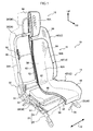
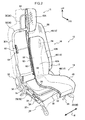
- the seat shell 12 is configured by: a cushion shell 40 that is supported so as to be movable in the up-down direction with respect to the cushion frame 28; a movable back shell 42 (a movable member) that is movable in the up-down direction with respect to the back frame 30 and supported so as to be capable of turning about an axis running along the seat width direction; and a non-movable back shell 46 (a non-movable member) that is attached to the back frame 30 so as to be incapable of displacement and that covers the back frame 30.
- the cushion shell 40 includes an outside shell 48 and an inside shell 50 formed by a rigid synthetic resin material.
- a thin pad member 52 formed by a foam body such as a urethane pad is interposed between the outside shell 48 and the inside shell 50.
- An upper face (front face of the outside shell 48) of the cushion shell 40 is formed so as to follow the shape of the buttocks and thighs of the seated person such that the buttocks and thighs of the seated person can be held comfortably.
- four attachment tabs 51 are fixed to a lower face of the cushion shell 40 (a lower face of the inside shell). Note that the cushion shell 40 is shown schematically in Fig. 3 .
- the cushion shell 40 described above is disposed above the cushion frame 28.
- Four attachment tabs 53 that correspond to the four attachment tabs 51 are fixed to an upper face of the cushion frame 28.
- Each of the attachment tabs 51, 53 are respectively coupled together by links 54.
- the links 54 configure a parallel link mechanism, and the cushion shell 40 is supported so as to be capable of moving in the up-down direction within a specific range with respect to the cushion frame 28. Note that a configuration employing a cross link mechanism may be used instead of the parallel link mechanism.
- a support pad 56 formed by a foam body such as a urethane pad is interposed between the cushion shell 40 and the cushion frame 28.
- a lower face of the support pad 56 is in contact with an upper face of the cushion frame 28, and an upper face of support pad 56 is in contact with a lower face of the cushion shell 40 (a lower face of the inside shell 50).
- the support pad 56 retains the cushion shell 40 at an upper end side of the movement range of the cushion shell 40 with respect to the cushion frame 28.
- the cushion shell 40 moves downwards due to resilient deformation of the support pad 56 when a person sits on the cushion shell 40.
- a comfortable ride for the seated person can be secured by resilient deformation of the support pad 56 in response to vehicle vibrations during vehicle travel.
- the support pad 56 is not limited to being formed by a foam body and may be configured for example by a metal spring, a pneumatic spring or a hydraulic cushion.
- the movable back shell 42 includes an outside shell 58 and an inside shell 60 that are formed by a rigid synthetic resin material.
- a thin pad member 62 formed by a foam body such as a urethane pad is interposed between the outside shell 58 and the inside shell 60.
- a front face of the movable back shell 42 (the top surface of the outside shell 58) is formed so as to follow the shape of the back of the seated person, such that the back of the seated person can be held comfortably.
- a center portion in the seat width direction of the movable back shell 42 configures a main body portion 42A that contacts the back of the seated person, and both end sides in the seat width direction of the movable back shell 42 configure side support portions 42B that bulge out further towards the front side of the seat than the main body portion 42A. Configuration is made such that the seated person is supported from the sides by the side support portions 42B.
- the materials for the outside shells 48, 58 and the inside shells 50, 60 are not limited to rigid synthetic resin materials, and light alloy materials of for example aluminum, FRP, wood and the like may also be used.
- the movable back shell 42 described above is disposed at a front side of the seatback with respect to the back frame 30, and is supported at the back frame 30 through a pair of left and right back shell support mechanisms 64.
- the back shell support mechanisms 64 couple the movable back shell 42 to the back frame 30 such that the movable back shell 42 can move in the up-down direction and turn about an axis running along the seat width direction.
- each back shell support mechanism 64 is configured by an attachment member 66, a slide rail 68, a slider 70 and an attachment plate 72.
- Each attachment member 66 is formed by for example a sheet metal material, and is fixed to a side frame 30A of the back frame 30 by means such as welding.
- the attachment member 66 is configured so as to absorb energy by undergoing plastic deformation in the event of a vehicle rear-end collision or the like.
- the slide rail 68 is fixed to the attachment member 66 by bolts 67 and nuts 69.
- the slide rail 68 is an elongated member with a hat-shaped cross-section and is disposed in a state wherein the length direction runs along the seatback height direction.
- the slider 70 is attached to the slide rail 68.
- the slider 70 is an elongated member with a substantially C-shaped cross-section, inside which the slide rail 68 fitted so as to be capable of sliding. The slider 70 is thereby slidable in the seatback height direction with respect to the slide rail 68.
- the attachment plate 72 is coupled to the slider 70 described above.
- the attachment plate 72 is an elongated, block shaped member, disposed in a state wherein the length direction runs along the seatback height direction.
- the attachment plate 72 includes a first attachment face 72A facing the slider 70 and a second attachment face 72B facing a back face of the movable back shell 42.
- a circular shaped bolt hole 74 is formed at the center of the first attachment face 72A, and oval shaped elongated holes 76 are respectively formed above and below the bolt hole 74.
- the bolt hole 74 and the elongated holes 76 penetrate the attachment plate 72 in the seat width direction.
- Bolts 78 pass through the slider 70 at three locations from top to bottom.
- the center bolt 78 passes through the bolt hole 74 at the center of the attachment plate 72 and is screwed together with a nut 79.
- the attachment plate 72 is thereby coupled to the slider 70 so as to be capable of rotating about the center bolt 78 (about an axis running along the seat width direction).
- Upper and lower bolts 78 are respectively passed though the upper and lower elongated holes 76 and screwed together with nuts 79.
- the turning range of the attachment plate 72 with respect to the slider 70 is thereby limited to within the range of the elongated holes 76.
- Plural bolt holes 80 that pass through the attachment plate 72 in the seatback front-rear direction and open onto the second attachment face 72B are formed to the attachment plate 72.
- the attachment plate 72 is bolted to the back face of the movable back shell 42 by bolts, not shown in the drawings, that are inserted through the bolt holes 80.
- the movable back shell 42 is thereby coupled to the back frame 30 through the back shell support mechanisms 64. Sliding of the sliders 70 with respect to the slide rails 68 in the back shell support mechanisms 64 permits relative movement in the up-down direction (up-down movement) of the movable back shell 42 with respect to the back frame 30, and also permits turning of the movable back shell 42 with respect to the back frame 30 due to turning of the attachment plate 72 with respect to the slider 70.
- configuration of the back shell support mechanism that couples the movable back shell 42 to the back frame 30 is not limited to that described above, and various changes may be made.
- a slide mechanism and a cross link mechanism may be combined to configure a mechanism that couples the back shell 42 to the back frame 30 so as to enable movement in the up-down direction and the front-rear direction.
- a lower end portion of the movable back shell 42 that is supported at the back frame 30 as described above is coupled to a rear end portion of the cushion shell 40 through a hinge 82.
- the movable back shell 42 is thereby coupled to the cushion shell 40 so as to be capable of turning about the hinge 82 (about an axis running along the seat width direction).
- Up-down movement of the cushion shell 40 is thereby accompanied by up-down movement of the movable back shell 42.
- the angle of inclination of the movable back shell 42 changes appropriately to suit the posture of the seated person.
- Fig. 1 illustrates a state wherein the cushion shell 40 and the movable back shell 42 are disposed at an upper end side of the up-down direction movement range
- Fig. 2 illustrates a state wherein the cushion shell 40 and the movable back shell 42 are disposed at a lower end side of the up-down direction movement range.
- the non-movable back shell 46 is disposed at a back face side of the movable back shell 42 described above.
- the non-movable back shell 46 is formed by a pad member 84 that is mounted to the back frame 30 and an outer cover member 86 that covers the pad member 84.
- the pad member 84 is made by a foam body such as a urethane foam
- the non-movable back shell 46 is attached to the back frame 30 so as to be incapable of displacement, and covers the back frame 30 from the outside.
- through holes are formed in the outer cover member 86 at locations facing the back shell support mechanisms 64, with the through holes covered by the movable back shell 42.
- the material for the outer cover member 86 and for example a fabric, a synthetic resin material, a light alloy material of for example aluminum, FRP or wood may be employed.
- the non-movable back shell 46 includes an integral headrest portion 46A, and the headrest frame 36 is covered by the headrest portion 46A.
- the external shape of portion of the seatback 16 that support the back of the seated person is configured by the movable back shell 42, and the external shape of other portions of the seatback 16 and the external shape of the headrest 18 are configured by the non-movable back shell 46.
- the non-movable back shell 46 is formed so as to be larger than the movable back shell 42, with an upper end side and both end sides in the seat width direction of the non-movable back shell 46 projecting out further towards the outside than the outer periphery of the movable back shell 42 as viewed from the front side of the seatback 16. Moreover, the both end sides in the seat width direction of the non-movable back shell 46 bulge out towards the front side of the seatback so as to follow the side support portions 42B of the movable back shell 42.
- the back of the seated person is supported by the movable back shell 42 that is supported so as to be capable of movement in the up-down direction with respect to the back frame 30.
- the non-movable back shell 46 that is attached to the back frame 30 so as to be incapable of displacement is disposed on the back face side of the movable back shell 42, and the back frame 30 is covered by the non-movable back shell 46. Accordingly, a favorable external appearance can be achieved with a simple configuration, even in a configuration provided with the movable back shell 42 that moves up and down with respect to the back frame 30.
- a back frame can be prevented from being exposed to the outside by providing a cover member such as a resin cover for example at a back face side of a seatback that is not covered by a back shell, or to headrest frame insertion holes formed to an upper face of a back shell.
- a cover member needs to be capable of covering up-down movement of the back shell, in other words, the cover member must for example be configured so as to undergo deformation following up-down movement of the back shell with respect to the back frame.
- the cover member would need to be set in a wide range over for example a back face side of the seatback.
- Such a cover member is not required in the present vehicle seat 10, thereby preventing or suppressing an increase in manufacturing cost or reduction in the flexibility in the layout of other components, as well as enabling an increase in flexibility for design.
- the non-movable back shell 46 disposed on the back face side of the movable back shell 42 of the present vehicle seat 10 is formed so as to be larger than the movable back shell 42, with the upper end side and both end sides in the seat width direction of the non-movable back shell 46 projecting out further towards the outside than the outer periphery of the movable back shell 42 as viewed from the front side of the seatback 16. Accordingly, a preferable dimensional relationship (distance) remains unchanged between the vehicle seat 10 and other vehicle components even with up-down movement of the movable back shell 42.
- the non-movable back shell 46 of the vehicle seat 10 is configured including the pad member 84 that is formed from a foam body such as urethane foam and is mounted to the back frame 30.
- a lightweight and inexpensive configuration can accordingly be achieved for the non-movable back shell 46.
- the non-movable back shell 46 is configured including the pad member 84, and can therefore be made soft to the touch for the occupant, enabling the comfort of the occupant to be increased.
- Both end sides in the seat width direction of the non-movable back shell 46 of the vehicle seat 10 bulge out towards the front side of the seatback following the side support portions 42B of the movable back shell 42.
- the movable back shell 42 and the non-movable back shell 46 thereby present a unified external look, enabling an excellent appearance to be achieved for the seatback 16.
- the non-movable back shell 46 of the vehicle seat 10 is integrally provided with the headrest portion 46A that covers the headrest frame 36, enabling a reduction in the number of components and a reduction in cost of the vehicle seat 10.
- the non-movable back shell 46 is configured integrally provided with the headrest portion 46A, however the invention according to claim 1 to claim 3 is not limited thereto, and in cases in which the seatback and the headrest are formed as separate bodies, the non-movable back shell is configured with the headrest portion omitted.
- non-movable back shell 46 is configured including the pad member 84, however the invention according to claim 1 and claim 2 is not limited thereto, and the configuration of the non-movable back shell may be modified as appropriate.
- configuration is made wherein the upper end side and both end sides in the seat width direction of the non-movable back shell 46 project out further towards the outside than the outer periphery of the movable back shell 42 as viewed from the front side of the seatback 16, however the invention according to claim 1 and claim 2 is not limited thereto, and configuration may be made such that the upper end side of the non-movable back shell is covered by the movable back shell as viewed from the seatback front side. Moreover, in the invention according to claim 1, configuration may be made such that the entire non-movable back shell is covered by the movable back shell as viewed from the seatback front side.
- the movable back shell 42 is supported so as to be capable of up-down movement and so as to be capable of turning about an axis running along the seat width direction with respect to the back frame 30, however the invention according to claim 1 is not limited thereto, and it is sufficient for the movable back shell 42 to be supported so as to be movable in at least the up-down direction with respect to the back frame 30.
Landscapes
- Engineering & Computer Science (AREA)
- Aviation & Aerospace Engineering (AREA)
- Transportation (AREA)
- Mechanical Engineering (AREA)
- Seats For Vehicles (AREA)
Applications Claiming Priority (2)
| Application Number | Priority Date | Filing Date | Title |
|---|---|---|---|
| JP2011221394A JP5859265B2 (ja) | 2011-10-05 | 2011-10-05 | 車両用シート |
| PCT/JP2012/072797 WO2013051364A1 (ja) | 2011-10-05 | 2012-09-06 | 車両用シート |
Publications (3)
| Publication Number | Publication Date |
|---|---|
| EP2765026A1 true EP2765026A1 (de) | 2014-08-13 |
| EP2765026A4 EP2765026A4 (de) | 2015-06-03 |
| EP2765026B1 EP2765026B1 (de) | 2017-12-20 |
Family
ID=48043532
Family Applications (1)
| Application Number | Title | Priority Date | Filing Date |
|---|---|---|---|
| EP12838155.5A Not-in-force EP2765026B1 (de) | 2011-10-05 | 2012-09-06 | Fahrzeugsitz |
Country Status (6)
| Country | Link |
|---|---|
| US (1) | US9555724B2 (de) |
| EP (1) | EP2765026B1 (de) |
| JP (1) | JP5859265B2 (de) |
| CN (1) | CN103857558B (de) |
| AU (1) | AU2012319835C1 (de) |
| WO (1) | WO2013051364A1 (de) |
Cited By (6)
| Publication number | Priority date | Publication date | Assignee | Title |
|---|---|---|---|---|
| US10021984B2 (en) | 2015-04-13 | 2018-07-17 | Steelcase Inc. | Seating arrangement |
| US10194750B2 (en) | 2015-04-13 | 2019-02-05 | Steelcase Inc. | Seating arrangement |
| US10966527B2 (en) | 2017-06-09 | 2021-04-06 | Steelcase Inc. | Seating arrangement and method of construction |
| US11109683B2 (en) | 2019-02-21 | 2021-09-07 | Steelcase Inc. | Body support assembly and method for the use and assembly thereof |
| US11259637B2 (en) | 2015-04-13 | 2022-03-01 | Steelcase Inc. | Seating arrangement |
| US11357329B2 (en) | 2019-12-13 | 2022-06-14 | Steelcase Inc. | Body support assembly and methods for the use and assembly thereof |
Families Citing this family (3)
| Publication number | Priority date | Publication date | Assignee | Title |
|---|---|---|---|---|
| JP6485731B2 (ja) * | 2014-11-28 | 2019-03-20 | いすゞ自動車株式会社 | 車両のサスペンションシート |
| JP7237445B2 (ja) * | 2017-06-14 | 2023-03-13 | 株式会社タチエス | 車両用シート |
| DE102019215450A1 (de) * | 2019-10-09 | 2021-04-15 | Psa Automobiles Sa | Gleitfläche für eine Rückenlehne eines Sitzes in einem Kraftfahrzeug |
Family Cites Families (46)
| Publication number | Priority date | Publication date | Assignee | Title |
|---|---|---|---|---|
| US3972565A (en) * | 1975-07-23 | 1976-08-03 | Edwin Smith | Couch |
| DE3008179C2 (de) * | 1980-03-04 | 1986-07-31 | Audi AG, 8070 Ingolstadt | Polstersitz für ein Kraftfahrzeug |
| JPS57120355U (de) * | 1981-01-21 | 1982-07-26 | ||
| JPS59101842A (ja) | 1982-12-02 | 1984-06-12 | Toshiba Corp | 樹脂封止用金型 |
| JPS59101842U (ja) * | 1982-12-27 | 1984-07-09 | 池田物産株式会社 | エア−マツト内蔵式シ−ト |
| BE897046A (fr) * | 1983-06-14 | 1983-10-03 | Mevergnies Marcel Neve De | Fauteuil pour vehicule, notamment automobile |
| DE3631872C1 (de) * | 1986-09-19 | 1987-10-01 | Daimler Benz Ag | Fahrzeugsitz |
| JPS63106935U (de) * | 1986-12-29 | 1988-07-11 | ||
| JP2818937B2 (ja) | 1988-01-06 | 1998-10-30 | エヌティーエンジニアリング株式会社 | 作業機械 |
| JPH01143957U (de) * | 1988-03-23 | 1989-10-03 | ||
| JPH01177948U (de) * | 1988-05-31 | 1989-12-20 | ||
| JPH057960Y2 (de) * | 1988-05-31 | 1993-03-01 | ||
| IT1223725B (it) * | 1988-07-25 | 1990-09-29 | Sicam Linea Srl | Sedile di autoveicolo |
| JPH0535859Y2 (de) * | 1989-04-28 | 1993-09-10 | ||
| JPH0672200A (ja) * | 1992-08-31 | 1994-03-15 | Ikeda Bussan Co Ltd | 座席装置 |
| JP2589861Y2 (ja) * | 1993-01-29 | 1999-02-03 | 日本発条株式会社 | 後席用パワーシート |
| JPH07257248A (ja) * | 1994-03-18 | 1995-10-09 | Aisin Seiki Co Ltd | 車両用中折れシート |
| US5533787A (en) * | 1994-03-25 | 1996-07-09 | Xiang; Kun | Add-on adjustable back support for car seat |
| GB9503222D0 (en) * | 1995-02-18 | 1995-04-05 | Britax Excelsior | Child safety net |
| US5909926A (en) * | 1996-09-04 | 1999-06-08 | Hi-Tech Seating Products, Inc. | Vehicle seating assembly |
| DE19649587A1 (de) * | 1996-11-29 | 1998-06-04 | Hs Tech & Design | Fahrzeugsitz |
| FR2781293B1 (fr) * | 1998-07-16 | 2000-10-06 | Labinal | Installation de pilotage d'au moins un module de siege |
| DE19853156B4 (de) * | 1998-11-18 | 2006-04-13 | Girsberger Holding Ag | Sitz |
| CH696482A5 (de) * | 2000-03-29 | 2007-07-13 | Stoll Giroflex Ag | Vorrichtung für eine Verstellung von einer ersten Komponente eines Stuhls gegenüber einer zweiten Komponente eines Stuhls. |
| JP3999453B2 (ja) * | 2000-10-16 | 2007-10-31 | コクヨ株式会社 | 椅子 |
| US20020060485A1 (en) * | 2000-11-17 | 2002-05-23 | Lear Corporation | Adjustable sport vehicle seat |
| FR2818595B1 (fr) * | 2000-12-26 | 2003-03-07 | Eads Sogerma | Fauteuil convertible en lit, notamment pour aeronef |
| SE0301293L (sv) * | 2003-05-05 | 2004-03-09 | Arjo Hospital Equipment Ab | Patientstol med sits förskjutbar i höjdled |
| DE10327639A1 (de) * | 2003-06-20 | 2005-01-13 | Recaro Gmbh & Co.Kg | Sportsitz für ein Fahrzeug, insbesondere für ein Kraftfahrzeug |
| JP4250128B2 (ja) * | 2003-09-29 | 2009-04-08 | 株式会社豊田中央研究所 | シート |
| US20050151405A1 (en) * | 2003-12-15 | 2005-07-14 | Be Aerospace, Inc. | Vehicle seating with protected living space |
| US7134729B2 (en) * | 2003-12-15 | 2006-11-14 | Be Aerospace, Inc. | Frame assembly for vehicle passenger seat |
| US7780230B2 (en) * | 2004-04-30 | 2010-08-24 | Hector Serber | Seat assembly with movable seat and backrest and method |
| US20060103211A1 (en) * | 2004-05-24 | 2006-05-18 | Pascal Garrido | Seat assembly with inner seat back movable with a seat cushion |
| JP4776895B2 (ja) * | 2004-07-05 | 2011-09-21 | 株式会社デルタツーリング | シート構造 |
| JP5155667B2 (ja) | 2005-01-18 | 2013-03-06 | 日本発條株式会社 | 車両用シート |
| JP4085415B2 (ja) * | 2006-09-27 | 2008-05-14 | テイ・エス テック株式会社 | 車両用シート |
| GB2442438A (en) | 2006-10-06 | 2008-04-09 | Dominic James Robinson | Adjustable seat with load cell and counterbalance |
| US7568764B2 (en) * | 2007-01-08 | 2009-08-04 | Ford Global Technologies, Llc | Reclining rear seat for vehicle having four-bar link |
| JP5125192B2 (ja) * | 2007-04-10 | 2013-01-23 | トヨタ紡織株式会社 | 車両用シート |
| US7950743B2 (en) * | 2008-02-05 | 2011-05-31 | Mark Kirgiss Clausen | Leg rest for economy class transportation seat |
| US8991930B2 (en) * | 2008-09-22 | 2015-03-31 | Johnson Controls Technology Company | Closed cell foam vehicle interior component and method of making same |
| JP5654273B2 (ja) * | 2009-09-04 | 2015-01-14 | デルタ工業株式会社 | 車両用シートバックフレームの構造 |
| BR112012019263A2 (pt) * | 2010-02-26 | 2019-09-24 | Lear Corp | "estrutura deformável, laminado de acabamento e elemento amortecedor dos componentes interiores automotivos" |
| EP2630004A1 (de) * | 2010-10-19 | 2013-08-28 | BAE Systems PLC | Fahrzeugsitz |
| JP6141736B2 (ja) * | 2013-09-26 | 2017-06-07 | 日本発條株式会社 | 車両用シート |
-
2011
- 2011-10-05 JP JP2011221394A patent/JP5859265B2/ja active Active
-
2012
- 2012-09-06 EP EP12838155.5A patent/EP2765026B1/de not_active Not-in-force
- 2012-09-06 CN CN201280048911.0A patent/CN103857558B/zh active Active
- 2012-09-06 US US14/349,309 patent/US9555724B2/en active Active
- 2012-09-06 AU AU2012319835A patent/AU2012319835C1/en not_active Ceased
- 2012-09-06 WO PCT/JP2012/072797 patent/WO2013051364A1/ja not_active Ceased
Cited By (16)
| Publication number | Priority date | Publication date | Assignee | Title |
|---|---|---|---|---|
| US11553797B2 (en) | 2015-04-13 | 2023-01-17 | Steelcase Inc. | Seating arrangement |
| US10194750B2 (en) | 2015-04-13 | 2019-02-05 | Steelcase Inc. | Seating arrangement |
| US10575648B2 (en) | 2015-04-13 | 2020-03-03 | Steelcase Inc. | Seating arrangement |
| US11963621B2 (en) | 2015-04-13 | 2024-04-23 | Steelcase Inc. | Seating arrangement |
| US11096497B2 (en) | 2015-04-13 | 2021-08-24 | Steelcase Inc. | Seating arrangement |
| US10021984B2 (en) | 2015-04-13 | 2018-07-17 | Steelcase Inc. | Seating arrangement |
| US11259637B2 (en) | 2015-04-13 | 2022-03-01 | Steelcase Inc. | Seating arrangement |
| US11324325B2 (en) | 2015-04-13 | 2022-05-10 | Steelcase Inc. | Seating arrangement |
| US11825955B2 (en) | 2017-06-09 | 2023-11-28 | Steelcase Inc. | Seating arrangement and method of construction |
| US10966527B2 (en) | 2017-06-09 | 2021-04-06 | Steelcase Inc. | Seating arrangement and method of construction |
| US12582234B2 (en) | 2017-06-09 | 2026-03-24 | Steelcase Inc. | Seating arrangement |
| US11109683B2 (en) | 2019-02-21 | 2021-09-07 | Steelcase Inc. | Body support assembly and method for the use and assembly thereof |
| US11357329B2 (en) | 2019-12-13 | 2022-06-14 | Steelcase Inc. | Body support assembly and methods for the use and assembly thereof |
| US11786039B2 (en) | 2019-12-13 | 2023-10-17 | Steelcase Inc. | Body support assembly and methods for the use and assembly thereof |
| US11805913B2 (en) | 2019-12-13 | 2023-11-07 | Steelcase Inc. | Body support assembly and methods for the use and assembly thereof |
| US12161232B2 (en) | 2019-12-13 | 2024-12-10 | Steelcase Inc. | Body support assembly and methods for the use and assembly thereof |
Also Published As
| Publication number | Publication date |
|---|---|
| WO2013051364A1 (ja) | 2013-04-11 |
| EP2765026B1 (de) | 2017-12-20 |
| AU2012319835C1 (en) | 2016-10-13 |
| JP2013082236A (ja) | 2013-05-09 |
| AU2012319835B2 (en) | 2016-06-23 |
| CN103857558A (zh) | 2014-06-11 |
| JP5859265B2 (ja) | 2016-02-10 |
| CN103857558B (zh) | 2016-06-22 |
| AU2012319835A1 (en) | 2014-04-17 |
| US20140265504A1 (en) | 2014-09-18 |
| US9555724B2 (en) | 2017-01-31 |
| EP2765026A4 (de) | 2015-06-03 |
Similar Documents
| Publication | Publication Date | Title |
|---|---|---|
| EP2765026B1 (de) | Fahrzeugsitz | |
| JP5544247B2 (ja) | 車両用シェル型シートのシートクッションシェルユニット及び車両用シェル型シート | |
| US20090134686A1 (en) | Vehicle seat | |
| JP7381945B2 (ja) | 乗物用シート | |
| JP7733332B2 (ja) | 乗物用シート | |
| JP2024045684A (ja) | 乗物用シート | |
| JP5448622B2 (ja) | 車両用シート | |
| WO2016076352A1 (ja) | 乗物用シート | |
| JP2024113116A5 (de) | ||
| CN105392668B (zh) | 交通工具用座椅 | |
| JP7239801B2 (ja) | 乗物用シート | |
| EP1838553B1 (de) | Fahrzeugsitz | |
| JP2019072244A (ja) | シートクッション | |
| JP7598016B2 (ja) | 乗物用シート | |
| JP7469618B2 (ja) | 乗り物用シート | |
| JP6126959B2 (ja) | 車両用シート | |
| JP2013230736A (ja) | 車両用シート | |
| JP2005145273A (ja) | 車両用シート | |
| JP2024174670A (ja) | 車両用シート | |
| KR100520209B1 (ko) | 자동차용 시트쿠션 프레임 | |
| JP6318075B2 (ja) | 乗物用シート | |
| JP2017030621A (ja) | 中折れシートバック |
Legal Events
| Date | Code | Title | Description |
|---|---|---|---|
| PUAI | Public reference made under article 153(3) epc to a published international application that has entered the european phase |
Free format text: ORIGINAL CODE: 0009012 |
|
| 17P | Request for examination filed |
Effective date: 20140331 |
|
| AK | Designated contracting states |
Kind code of ref document: A1 Designated state(s): AL AT BE BG CH CY CZ DE DK EE ES FI FR GB GR HR HU IE IS IT LI LT LU LV MC MK MT NL NO PL PT RO RS SE SI SK SM TR |
|
| DAX | Request for extension of the european patent (deleted) | ||
| RA4 | Supplementary search report drawn up and despatched (corrected) |
Effective date: 20150504 |
|
| RIC1 | Information provided on ipc code assigned before grant |
Ipc: B60N 2/50 20060101ALI20150424BHEP Ipc: B60N 2/64 20060101AFI20150424BHEP Ipc: B60N 2/20 20060101ALI20150424BHEP Ipc: B60N 2/06 20060101ALI20150424BHEP Ipc: B60N 2/70 20060101ALI20150424BHEP Ipc: B60N 2/48 20060101ALI20150424BHEP Ipc: B60N 2/22 20060101ALI20150424BHEP |
|
| RAP1 | Party data changed (applicant data changed or rights of an application transferred) |
Owner name: NHK SPRING CO., LTD. |
|
| 17Q | First examination report despatched |
Effective date: 20161222 |
|
| GRAP | Despatch of communication of intention to grant a patent |
Free format text: ORIGINAL CODE: EPIDOSNIGR1 |
|
| INTG | Intention to grant announced |
Effective date: 20170801 |
|
| GRAS | Grant fee paid |
Free format text: ORIGINAL CODE: EPIDOSNIGR3 |
|
| GRAA | (expected) grant |
Free format text: ORIGINAL CODE: 0009210 |
|
| AK | Designated contracting states |
Kind code of ref document: B1 Designated state(s): AL AT BE BG CH CY CZ DE DK EE ES FI FR GB GR HR HU IE IS IT LI LT LU LV MC MK MT NL NO PL PT RO RS SE SI SK SM TR |
|
| REG | Reference to a national code |
Ref country code: GB Ref legal event code: FG4D |
|
| REG | Reference to a national code |
Ref country code: CH Ref legal event code: EP |
|
| REG | Reference to a national code |
Ref country code: IE Ref legal event code: FG4D |
|
| REG | Reference to a national code |
Ref country code: AT Ref legal event code: REF Ref document number: 956054 Country of ref document: AT Kind code of ref document: T Effective date: 20180115 |
|
| REG | Reference to a national code |
Ref country code: DE Ref legal event code: R096 Ref document number: 602012041204 Country of ref document: DE |
|
| REG | Reference to a national code |
Ref country code: NL Ref legal event code: MP Effective date: 20171220 |
|
| PG25 | Lapsed in a contracting state [announced via postgrant information from national office to epo] |
Ref country code: LT Free format text: LAPSE BECAUSE OF FAILURE TO SUBMIT A TRANSLATION OF THE DESCRIPTION OR TO PAY THE FEE WITHIN THE PRESCRIBED TIME-LIMIT Effective date: 20171220 Ref country code: FI Free format text: LAPSE BECAUSE OF FAILURE TO SUBMIT A TRANSLATION OF THE DESCRIPTION OR TO PAY THE FEE WITHIN THE PRESCRIBED TIME-LIMIT Effective date: 20171220 Ref country code: SE Free format text: LAPSE BECAUSE OF FAILURE TO SUBMIT A TRANSLATION OF THE DESCRIPTION OR TO PAY THE FEE WITHIN THE PRESCRIBED TIME-LIMIT Effective date: 20171220 Ref country code: NO Free format text: LAPSE BECAUSE OF FAILURE TO SUBMIT A TRANSLATION OF THE DESCRIPTION OR TO PAY THE FEE WITHIN THE PRESCRIBED TIME-LIMIT Effective date: 20180320 |
|
| REG | Reference to a national code |
Ref country code: LT Ref legal event code: MG4D |
|
| REG | Reference to a national code |
Ref country code: AT Ref legal event code: MK05 Ref document number: 956054 Country of ref document: AT Kind code of ref document: T Effective date: 20171220 |
|
| PG25 | Lapsed in a contracting state [announced via postgrant information from national office to epo] |
Ref country code: LV Free format text: LAPSE BECAUSE OF FAILURE TO SUBMIT A TRANSLATION OF THE DESCRIPTION OR TO PAY THE FEE WITHIN THE PRESCRIBED TIME-LIMIT Effective date: 20171220 Ref country code: RS Free format text: LAPSE BECAUSE OF FAILURE TO SUBMIT A TRANSLATION OF THE DESCRIPTION OR TO PAY THE FEE WITHIN THE PRESCRIBED TIME-LIMIT Effective date: 20171220 Ref country code: GR Free format text: LAPSE BECAUSE OF FAILURE TO SUBMIT A TRANSLATION OF THE DESCRIPTION OR TO PAY THE FEE WITHIN THE PRESCRIBED TIME-LIMIT Effective date: 20180321 Ref country code: BG Free format text: LAPSE BECAUSE OF FAILURE TO SUBMIT A TRANSLATION OF THE DESCRIPTION OR TO PAY THE FEE WITHIN THE PRESCRIBED TIME-LIMIT Effective date: 20180320 Ref country code: HR Free format text: LAPSE BECAUSE OF FAILURE TO SUBMIT A TRANSLATION OF THE DESCRIPTION OR TO PAY THE FEE WITHIN THE PRESCRIBED TIME-LIMIT Effective date: 20171220 |
|
| PG25 | Lapsed in a contracting state [announced via postgrant information from national office to epo] |
Ref country code: NL Free format text: LAPSE BECAUSE OF FAILURE TO SUBMIT A TRANSLATION OF THE DESCRIPTION OR TO PAY THE FEE WITHIN THE PRESCRIBED TIME-LIMIT Effective date: 20171220 |
|
| PG25 | Lapsed in a contracting state [announced via postgrant information from national office to epo] |
Ref country code: CY Free format text: LAPSE BECAUSE OF FAILURE TO SUBMIT A TRANSLATION OF THE DESCRIPTION OR TO PAY THE FEE WITHIN THE PRESCRIBED TIME-LIMIT Effective date: 20171220 Ref country code: EE Free format text: LAPSE BECAUSE OF FAILURE TO SUBMIT A TRANSLATION OF THE DESCRIPTION OR TO PAY THE FEE WITHIN THE PRESCRIBED TIME-LIMIT Effective date: 20171220 Ref country code: SK Free format text: LAPSE BECAUSE OF FAILURE TO SUBMIT A TRANSLATION OF THE DESCRIPTION OR TO PAY THE FEE WITHIN THE PRESCRIBED TIME-LIMIT Effective date: 20171220 Ref country code: ES Free format text: LAPSE BECAUSE OF FAILURE TO SUBMIT A TRANSLATION OF THE DESCRIPTION OR TO PAY THE FEE WITHIN THE PRESCRIBED TIME-LIMIT Effective date: 20171220 Ref country code: CZ Free format text: LAPSE BECAUSE OF FAILURE TO SUBMIT A TRANSLATION OF THE DESCRIPTION OR TO PAY THE FEE WITHIN THE PRESCRIBED TIME-LIMIT Effective date: 20171220 |
|
| PG25 | Lapsed in a contracting state [announced via postgrant information from national office to epo] |
Ref country code: AT Free format text: LAPSE BECAUSE OF FAILURE TO SUBMIT A TRANSLATION OF THE DESCRIPTION OR TO PAY THE FEE WITHIN THE PRESCRIBED TIME-LIMIT Effective date: 20171220 Ref country code: SM Free format text: LAPSE BECAUSE OF FAILURE TO SUBMIT A TRANSLATION OF THE DESCRIPTION OR TO PAY THE FEE WITHIN THE PRESCRIBED TIME-LIMIT Effective date: 20171220 Ref country code: RO Free format text: LAPSE BECAUSE OF FAILURE TO SUBMIT A TRANSLATION OF THE DESCRIPTION OR TO PAY THE FEE WITHIN THE PRESCRIBED TIME-LIMIT Effective date: 20171220 Ref country code: IS Free format text: LAPSE BECAUSE OF FAILURE TO SUBMIT A TRANSLATION OF THE DESCRIPTION OR TO PAY THE FEE WITHIN THE PRESCRIBED TIME-LIMIT Effective date: 20180420 Ref country code: PL Free format text: LAPSE BECAUSE OF FAILURE TO SUBMIT A TRANSLATION OF THE DESCRIPTION OR TO PAY THE FEE WITHIN THE PRESCRIBED TIME-LIMIT Effective date: 20171220 |
|
| REG | Reference to a national code |
Ref country code: DE Ref legal event code: R097 Ref document number: 602012041204 Country of ref document: DE |
|
| PLBE | No opposition filed within time limit |
Free format text: ORIGINAL CODE: 0009261 |
|
| STAA | Information on the status of an ep patent application or granted ep patent |
Free format text: STATUS: NO OPPOSITION FILED WITHIN TIME LIMIT |
|
| 26N | No opposition filed |
Effective date: 20180921 |
|
| PG25 | Lapsed in a contracting state [announced via postgrant information from national office to epo] |
Ref country code: DK Free format text: LAPSE BECAUSE OF FAILURE TO SUBMIT A TRANSLATION OF THE DESCRIPTION OR TO PAY THE FEE WITHIN THE PRESCRIBED TIME-LIMIT Effective date: 20171220 |
|
| PG25 | Lapsed in a contracting state [announced via postgrant information from national office to epo] |
Ref country code: SI Free format text: LAPSE BECAUSE OF FAILURE TO SUBMIT A TRANSLATION OF THE DESCRIPTION OR TO PAY THE FEE WITHIN THE PRESCRIBED TIME-LIMIT Effective date: 20171220 |
|
| REG | Reference to a national code |
Ref country code: DE Ref legal event code: R119 Ref document number: 602012041204 Country of ref document: DE |
|
| PG25 | Lapsed in a contracting state [announced via postgrant information from national office to epo] |
Ref country code: MC Free format text: LAPSE BECAUSE OF FAILURE TO SUBMIT A TRANSLATION OF THE DESCRIPTION OR TO PAY THE FEE WITHIN THE PRESCRIBED TIME-LIMIT Effective date: 20171220 |
|
| REG | Reference to a national code |
Ref country code: CH Ref legal event code: PL |
|
| GBPC | Gb: european patent ceased through non-payment of renewal fee |
Effective date: 20180906 |
|
| REG | Reference to a national code |
Ref country code: BE Ref legal event code: MM Effective date: 20180930 |
|
| REG | Reference to a national code |
Ref country code: IE Ref legal event code: MM4A |
|
| PG25 | Lapsed in a contracting state [announced via postgrant information from national office to epo] |
Ref country code: LU Free format text: LAPSE BECAUSE OF NON-PAYMENT OF DUE FEES Effective date: 20180906 |
|
| PG25 | Lapsed in a contracting state [announced via postgrant information from national office to epo] |
Ref country code: IE Free format text: LAPSE BECAUSE OF NON-PAYMENT OF DUE FEES Effective date: 20180906 Ref country code: IT Free format text: LAPSE BECAUSE OF NON-PAYMENT OF DUE FEES Effective date: 20180906 Ref country code: DE Free format text: LAPSE BECAUSE OF NON-PAYMENT OF DUE FEES Effective date: 20190402 |
|
| PG25 | Lapsed in a contracting state [announced via postgrant information from national office to epo] |
Ref country code: CH Free format text: LAPSE BECAUSE OF NON-PAYMENT OF DUE FEES Effective date: 20180930 Ref country code: LI Free format text: LAPSE BECAUSE OF NON-PAYMENT OF DUE FEES Effective date: 20180930 Ref country code: FR Free format text: LAPSE BECAUSE OF NON-PAYMENT OF DUE FEES Effective date: 20180930 Ref country code: BE Free format text: LAPSE BECAUSE OF NON-PAYMENT OF DUE FEES Effective date: 20180930 |
|
| PG25 | Lapsed in a contracting state [announced via postgrant information from national office to epo] |
Ref country code: GB Free format text: LAPSE BECAUSE OF NON-PAYMENT OF DUE FEES Effective date: 20180906 |
|
| PG25 | Lapsed in a contracting state [announced via postgrant information from national office to epo] |
Ref country code: MT Free format text: LAPSE BECAUSE OF NON-PAYMENT OF DUE FEES Effective date: 20180906 |
|
| PG25 | Lapsed in a contracting state [announced via postgrant information from national office to epo] |
Ref country code: TR Free format text: LAPSE BECAUSE OF FAILURE TO SUBMIT A TRANSLATION OF THE DESCRIPTION OR TO PAY THE FEE WITHIN THE PRESCRIBED TIME-LIMIT Effective date: 20171220 |
|
| PG25 | Lapsed in a contracting state [announced via postgrant information from national office to epo] |
Ref country code: HU Free format text: LAPSE BECAUSE OF FAILURE TO SUBMIT A TRANSLATION OF THE DESCRIPTION OR TO PAY THE FEE WITHIN THE PRESCRIBED TIME-LIMIT; INVALID AB INITIO Effective date: 20120906 Ref country code: PT Free format text: LAPSE BECAUSE OF FAILURE TO SUBMIT A TRANSLATION OF THE DESCRIPTION OR TO PAY THE FEE WITHIN THE PRESCRIBED TIME-LIMIT Effective date: 20171220 |
|
| PG25 | Lapsed in a contracting state [announced via postgrant information from national office to epo] |
Ref country code: MK Free format text: LAPSE BECAUSE OF NON-PAYMENT OF DUE FEES Effective date: 20171220 |
|
| PG25 | Lapsed in a contracting state [announced via postgrant information from national office to epo] |
Ref country code: AL Free format text: LAPSE BECAUSE OF FAILURE TO SUBMIT A TRANSLATION OF THE DESCRIPTION OR TO PAY THE FEE WITHIN THE PRESCRIBED TIME-LIMIT Effective date: 20171220 |