EP2768342B1 - Anordnung mit einer verbindungsvorrichtung zum verbinden zweier rechtwinklig anzuordnender schubladenwandteile - Google Patents
Anordnung mit einer verbindungsvorrichtung zum verbinden zweier rechtwinklig anzuordnender schubladenwandteile Download PDFInfo
- Publication number
- EP2768342B1 EP2768342B1 EP12775425.7A EP12775425A EP2768342B1 EP 2768342 B1 EP2768342 B1 EP 2768342B1 EP 12775425 A EP12775425 A EP 12775425A EP 2768342 B1 EP2768342 B1 EP 2768342B1
- Authority
- EP
- European Patent Office
- Prior art keywords
- drawer
- receiving portion
- clip
- arrangement according
- receiving
- Prior art date
- Legal status (The legal status is an assumption and is not a legal conclusion. Google has not performed a legal analysis and makes no representation as to the accuracy of the status listed.)
- Active
Links
Images



Classifications
-
- A—HUMAN NECESSITIES
- A47—FURNITURE; DOMESTIC ARTICLES OR APPLIANCES; COFFEE MILLS; SPICE MILLS; SUCTION CLEANERS IN GENERAL
- A47B—TABLES; DESKS; OFFICE FURNITURE; CABINETS; DRAWERS; GENERAL DETAILS OF FURNITURE
- A47B88/00—Drawers for tables, cabinets or like furniture; Guides for drawers
- A47B88/90—Constructional details of drawers
- A47B88/941—Drawers being constructed from two or more parts
-
- A—HUMAN NECESSITIES
- A47—FURNITURE; DOMESTIC ARTICLES OR APPLIANCES; COFFEE MILLS; SPICE MILLS; SUCTION CLEANERS IN GENERAL
- A47B—TABLES; DESKS; OFFICE FURNITURE; CABINETS; DRAWERS; GENERAL DETAILS OF FURNITURE
- A47B88/00—Drawers for tables, cabinets or like furniture; Guides for drawers
- A47B88/90—Constructional details of drawers
- A47B2088/902—Corner connectors for drawers
-
- F—MECHANICAL ENGINEERING; LIGHTING; HEATING; WEAPONS; BLASTING
- F16—ENGINEERING ELEMENTS AND UNITS; GENERAL MEASURES FOR PRODUCING AND MAINTAINING EFFECTIVE FUNCTIONING OF MACHINES OR INSTALLATIONS; THERMAL INSULATION IN GENERAL
- F16B—DEVICES FOR FASTENING OR SECURING CONSTRUCTIONAL ELEMENTS OR MACHINE PARTS TOGETHER, e.g. NAILS, BOLTS, CIRCLIPS, CLAMPS, CLIPS OR WEDGES; JOINTS OR JOINTING
- F16B12/00—Jointing of furniture or the like, e.g. hidden from exterior
- F16B12/44—Leg joints; Corner joints
- F16B12/46—Non-metal corner connections
Definitions
- the present invention relates to an arrangement with at least two drawer wall parts to be arranged at right angles, which are connected to one another or connectable to one another via a connecting device. Furthermore, the invention relates to a drawer with a rear wall, a front wall and two side walls, wherein at least two of these walls are connected to one another with a connecting device of the type to be described or connected to each other.
- Such connecting devices are used for the assembly of drawer wall parts, wherein it is provided in particular that a first drawer wall part is designed as a decorative, plate-shaped insert - for example made of glass, plastic, wood, stone or ceramic, via the connecting device with a profile wall made of metal or plastic to connect.
- a first drawer wall part is designed as a decorative, plate-shaped insert - for example made of glass, plastic, wood, stone or ceramic, via the connecting device with a profile wall made of metal or plastic to connect.
- the manual assembly or separation of connected drawer wall parts should also be possible without the use of a tool.
- Object of the present invention is to propose an arrangement with a connecting device of the type mentioned, which makes the above requirements sufficient.
- a receiving part is provided with a receiving opening into which an end portion of the first drawer wall part can be inserted.
- the U-shaped bracket with the at least two parallel legs serves to attach the receiving part on the second drawer wall part, wherein during mounting a leg of the clip is inserted into the intended insertion opening of the receiving part and wherein the two legs of the clip together a web of the second Embrace the drawer wall part, so that the receiving part (and thus the first drawer wall part) is non-positively and / or positively fixed relative to the web of the second drawer wall part.
- the receiving opening of the receiving part is formed as a push-in pocket, which in the mounting position substantially completely surrounds the end portion of the first drawer wall part.
- a front end of the first drawer wall part can be inserted.
- the receiving part has at least one insertion funnel through which a leg of the clip can be guided in the insertion opening of the receiving part.
- the insertion funnel can have at least one - preferably two mutually converging - inclined surfaces which at least one leg of the clip can be guided in the direction of the insertion opening of the receiving part.
- the receiving part and / or the clamp may be made of plastic, wherein it is preferably provided that these components are designed as integrally formed injection-molded parts. This allows a trouble-free and cost-effective production of the receiving part and / or the clip.
- the drawer according to the invention has a rear wall, a front panel and two side walls, wherein at least two of these walls are connected to each other with a connecting device of the type in question.
- the rear wall, the front panel and / or at least one side wall can have a drawer wall part designed as a plate-shaped insert, preferably made of glass, plastic, wood, stone or ceramic, the panel-shaped insert being provided with a profile wall, preferably made of metal or plastic, via the connecting device. connected is.
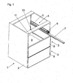
- Fig. 1 shows a piece of furniture 1 in a perspective view.
- the furniture 1 has a plurality of drawers 3, which are movably mounted on Schubladenauszieh Installationen 4 relative to a cabinet-shaped furniture body 2.
- the drawer pull-out guide 4 has, in a known manner, a cabinet rail 5 to be fastened to the furniture body 2, a drawer rail 7 to be fastened to the drawer 3 and a middle rail 6 movably arranged between the cabinet rail 5 and the drawer rail 7.
- the drawers 3 each have a front panel 8, a drawer bottom 9, drawer side walls 10 and a rear wall 11.
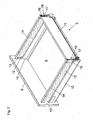
- Fig. 2 shows a drawer 3 in a perspective view from behind.
- the drawer 3 comprises a front panel 8, a drawer bottoms 9, side walls 10 and a rear wall 11.
- Above the side walls 10 each have a first drawer wall part 12 is arranged, which can be formed, for example, as a plate-shaped insert made of glass, wood, metal, plastic or ceramic.
- first drawer wall part 12 is arranged, which can be formed, for example, as a plate-shaped insert made of glass, wood, metal, plastic or ceramic.
- railing struts 14 are arranged.
- On the front panel 8, a fitting body 13 is mounted, which has a (not apparent here) recess for receiving the front end portion of the first drawer warp part 12.
- the rear end portion of the drawer wall part 12 is connected via the connecting device 15 with the rear wall 11, which forms the second drawer wall part in the illustrated embodiment.
- the connecting device 15 comprises a receiving part 16 with a receiving opening 20 (FIG. Fig. 3 ), in which the rear end portion of the drawer wall part 12 is inserted.
- Fig. 3 shows the drawer 3 in a perspective view, wherein one side of the drawer 3 is shown in an exploded view.
- a fitting body 13 is to be mounted, which receives the front end portion of the drawer wall part 12 and which is formed at the same time for fastening the front end of the rail strut 14.
- the fitting body 13 is made in two parts and includes one the front panel 8 mounting part 18 to be mounted on a holder 19 can be snapped.
- the holder 19 has a pocket-shaped recess for receiving the front end portion of the first drawer wall part 12.
- the side walls 10 of the drawer 3 are formed as hollow profiles, preferably made of metal or plastic.
- the connecting device 15 comprises a receiving part 16 with a vertically extending in the mounting position receiving opening 20 for receiving the rear end portion of the drawer wall part 12.
- a bracket 17 the receiving part 16 relative to a arranged on the rear wall 11 or web 21 are fixed.
- the rear wall 11 is formed of a profile wall made of metal or plastic, wherein the web 21 projects from the rear wall 11 at right angles to the rear.
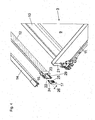
- Fig. 4 shows the rear end portion of the drawer 3 in a perspective view from above. Recognizable is the drawer 3 with the drawer bottom 9, the side wall 3 and the rear wall 11, from which the web 21 projects to the rear.
- the receiving part 16 is attached to the rear end of the drawer wall part 12, so that the drawer wall part 12 in the receiving opening 20 (FIG. Fig. 3 ) of the receiving part 16 is held.
- the receiving part 16 is provided with a resilient tongue 23 which rests in the mounted position on a front side of the drawer wall part 12, wherein a longitudinal displacement of the drawer wall part 12 is prevented by the tongue 23 during insertion or withdrawal of the drawer 3 relative to the furniture body 2.
- the receiving part 16 further comprises a push-in opening 22, which is provided for receiving the clip 17.
- the bracket 17 comprises two spaced apart legs 24, 25, between which a gap 26 remains.
- the leg 24 of the bracket 17 is inserted into the insertion opening 22 of the receiving part 12, the other leg 25 of the bracket 17 is in mounting position on the inside of the web 21, so that the web 21 of the rear wall 11 in the assembled state in which between the legs 24th , 25 formed gap 26 is received.
- an insertion funnel 29 is provided with at least one inclined surface, through which the clip 17 can be guided in the insertion opening 22 of the receiving part 16.
- Fig. 5a shows the rear end portion of the drawer 3 in a perspective view from above. Visible is the mounting position of the drawer wall part 12, one limb 24 ( Fig. 4 ) of the clip 17 is received in the insertion opening 22 of the receiving part 16 and wherein the other leg 25 of the clip 17 rests against the inside of the web 21 of the rear wall 11, so that the web 21 between the two legs 24, 25 of the clip 17 is held.
- Fig. 5b shows the connecting device 15 in the drawer wall 12 holding position in cross section, wherein the rear end portion of the drawer wall part 12 is mounted in the receiving opening 20 of the receiving part 16.
- One leg 24 of the bracket 17 is inserted in the receiving part 16, the other leg 25 of the bracket 17 abuts the angled web 21 of the rear wall 11, so that the web 21 between the two legs 24, 25 of the bracket 17 is received.
- Fig. 6a shows the bracket 17 in a perspective view while Fig. 6b the bracket 17 in a plan view shows.
- the bracket 17 has at least two spaced apart legs 24 and 25, between which a gap 26 remains. In the figure shown, the legs 24, 25 have a different length.
- Recognizable is a snap connection 27 with elastically bendable locking parts 28 which are releasably locked in the drawer wall part 12 holding position with a predetermined attachment point of the receiving part 16. By the locking elements 28, an unintentional release of the bracket 17 relative to the receiving part 16 can be prevented.
- Fig. 7a and Fig. 7b show the rear end of the drawer 3 with the bracket 17 in the released position and in the mounting position.
- the leg 24 is inserted into the insertion opening 22 (FIG. Fig. 4 ) of the receiving part 16 is inserted, the other leg 25 is in the mounting position on the web 21 of the rear wall 11 at.
Landscapes
- Drawers Of Furniture (AREA)
- Connection Of Plates (AREA)
- Furniture Connections (AREA)
Description
- Die vorliegende Erfindung bezieht sich auf eine Anordnung mit wenigstens zwei rechtwinklig anzuordnenden Schubladenwandteilen, die über eine Verbindungsvorrichtung miteinander verbunden oder miteinander verbindbar sind. Ferner betrifft die Erfindung eine Schublade mit einer Rückwand, einer Frontwand und zwei Seitenwänden, wobei zumindest zwei dieser Wände mit einer Verbindungsvorrichtung der zu beschreibenden Art miteinander verbindbar oder miteinander verbunden sind.
- >
- Derartige Verbindungsvorrichtungen werden für den Zusammenbau von Schubladenwandteilen verwendet, wobei insbesondere vorgesehen ist, dass ein erstes Schubladenwandteil als dekorativer, plattenförmiger Einsatz - beispielsweise aus Glas, Kunststoff, Holz, Stein oder Keramik ausgebildet ist, der über die Verbindungsvorrichtung mit einer Profilwand aus Metall oder Kunststoff zu verbinden ist. Generell ist es wünschenswert, wenn die Montage bzw. Demontage der Schubladenwandteile einfach durchzuführen ist und auf komplexe Bauteile der Verbindungsvorrichtung verzichtet werden kann. Das manuelle Zusammenfügen bzw. die Trennung von verbundenen Schubladenwandteilen soll auch ohne die Verwendung eines Werkzeuges erfolgen können.
- Aufgabe der vorliegenden Erfindung ist, eine Anordnung mit einer Verbindungsvorrichtung der eingangs erwähnten Gattung vorzuschlagen, welche den oben genannten Erfordernissen Genüge leistet.
- Dies wird erfindungsgemäß durch die Merkmale des Patentanspruchs 1 gelöst. Vorteilhafte Ausgestaltungen der Erfindung sind in den Unteransprüchen angegeben. In der
DE 20200900498241 - Die erfindungsgemäße Anordnung mit einer Verbindungsvorrichtung zum Verbinden zweier rechtwinklig anzuordnender Schubladenwandteile weist die Kombination folgender Merkmale auf:
- zumindest ein Aufnahmeteil, welches eine Aufnahmeöffnung zur Aufnahme eines Endabschnittes des ersten Schubladenwandteiles und wenigstens eine Einschiebeöffnung aufweist,
- eine Klammer, welche zumindest zwei im Wesentlichen parallel verlaufende Schenkel aufweist, wobei die Klammer zum Verbinden der beiden Schubladenwandteile auf einen am zweiten Schubladenwandteil angeordneten oder ausgebildeten Steg aufschiebbar ist und wobei die beiden Schenkel der Klammer den Steg des zweiten Schubladenwandteiles umgreifen, wobei ein erster Schenkel der Klammer in die Einschiebeöffnung des Aufnahmeteiles einschiebbar ist und den Aufnahmeteil lagesicher mit dem zweiten Schubladenwandteil verbindet.
- Mit anderen Worten ist ein Aufnahmeteil mit einer Aufnahmeöffnung vorgesehen, in die ein Endabschnitt des ersten Schubladenwandteiles einsteckbar ist. Die U-förmig ausgebildete Klammer mit den wenigstens zwei parallel verlaufenden Schenkeln dient zur Befestigung des Aufnahmeteiles am zweiten Schubladenwandteil, wobei bei der Montage ein Schenkel der Klammer in die vorgesehene Einstecköffnung des Aufnahmeteiles einzustecken ist und wobei die beiden Schenkel der Klammer gemeinsam einen Steg des zweiten Schubladenwandteiles umgreifen, sodass das Aufnahmeteil (und damit das erste Schubladenwandteil) kraftschlüssig und/oder formschlüssig relativ zum Steg des zweiten Schubladenwandteiles fixierbar ist.
- Gemäß einem Ausführungsbeispiel der Erfindung kann vorgesehen sein, dass die Aufnahmeöffnung des Aufnahmeteiles als Einstecktasche ausbildet ist, welche in Montagelage den Endabschnitt des ersten Schubladenwandteiles im Wesentlichen vollständig umgreift. In diese Einstecktasche kann ein stirnseitiges Ende des ersten Schubladenwandteiles eingesteckt werden.
- Um das Einstecken der Klammer in die Einstecköffnung des Aufnahmeteiles zu erleichtern kann vorgesehen sein, dass das Aufnahmeteil zumindest einen Einführtrichter aufweist, durch den ein Schenkel der Klammer in die Einschiebeöffnung des Aufnahmeteiles führbar ist. Der Einführtrichter kann hierfür zwei zumindest eine - vorzugsweise zwei zueinander konvergierende - Schrägflächen aufweisen, durch welche zumindest ein Schenkel der Klammer in Richtung der Einschiebeöffnung des Aufnahmeteiles führbar ist.
- Das Aufnahmeteil und/oder die Klammer kann aus Kunststoff bestehen, wobei vorzugsweise vorgesehen ist, dass diese Bauteile als einstückig ausgebildete Spritzgussteile ausgeführt sind. Dies erlaubt eine problemlose und kostengünstige Herstellung des Aufnahmeteiles und/oder der Klammer.
- Die erfindungsgemäße Schublade weist eine Rückwand, eine Frontblende und zwei Seitenwände auf, wobei zumindest zwei dieser Wände mit einer Verbindungsvorrichtung der in Rede stehenden Art miteinander verbunden sind. Die Rückwand, die Frontblende und/oder wenigstens eine Seitenwand kann ein als plattenförmigen Einsatz, vorzugsweise aus Glas, Kunststoff, Holz, Stein oder Keramik, ausgebildetes Schubladenwandteil aufweisen, wobei der plattenförmige Einsatz über die Verbindungsvorrichtung mit einer Profilwand, vorzugsweise aus Metall oder Kunststoff, verbunden ist.
- Weitere Einzelheiten und Vorteile der vorliegenden Erfindung werden anhand des in den Zeichnungen dargestellten Ausführungsbeispieles erläutert. Dabei zeigt bzw. zeigen:
- Fig. 1
- ein Möbel mit einem Möbelkorpus und verfahrbaren Schubladen in einer perspektivischen Darstellung,
- Fig. 2
- eine Schublade in einer perspektivischen Ansicht,
- Fig. 3
- die Schublade gemäß
Fig. 2 mit einer Seite in einer Explosionsdarstellung, - Fig. 4
- der hintere Endbereich der Schublade in einer Explosionsdarstellung,
- Fig.5a, 5b
- der hintere Endbereich der Schublade mit montiertem Schubladenwandteil sowie die Verbindungsvorrichtung in der das Schubladenwandteil haltenden Stellung im Querschnitt,
- Fig. 6a, 6b
- die Klammer der Verbindungsvorrichtung in zwei verschiedenen Ansichten,
- Fig. 7a, 7b
- den hinteren Endbereich der Schublade mit der aufzusteckenden Klammer sowie die Montagestellung der Klammer.
-
Fig. 1 zeigt ein Möbel 1 in einer perspektivischen Darstellung. Das Möbel 1 weist mehrere Schubladen 3 auf, welche über Schubladenausziehführungen 4 relativ zu einem schrankförmigen Möbelkorpus 2 verfahrbar gelagert sind. Die Schubladenausziehführung 4 weist in bekannter Weise eine am Möbelkorpus 2 zu befestigende Korpusschiene 5, eine an der Schublade 3 zu befestigende Ladenschiene 7 sowie eine zwischen der Korpusschiene 5 und der Ladenschiene 7 verfahrbar angeordnete Mittelschiene 6 auf. Die Schubladen 3 weisen jeweils eine Frontblende 8, einen Schubladenboden 9, Schubladenseitenwände 10 sowie eine Rückwand 11 auf. -
Fig. 2 zeigt eine Schublade 3 in einer perspektivischen Ansicht von hinten. Die Schublade 3 umfasst eine Frontblende 8, einen Schubladenböden 9, Seitenwände 10 sowie eine Rückwand 11. Oberhalb der Seitenwände 10 ist jeweils ein erstes Schubladenwandteil 12 angeordnet, welches beispielsweise als plattenförmiger Einsatz aus Glas, Holz, Metall, Kunststoff oder Keramik ausgebildet werden kann. Über den ersten Schubladenwandteilen 12 sind Relingstreben 14 angeordnet. An der Frontblende 8 ist ein Beschlagkörper 13 gelagert, der eine (hier nicht ersichtliche) Ausnehmung zur Aufnahme des frontseitigen Endabschnittes des ersten Schubladenwaridteiles 12 aufweist. Der rückseitige Endabschnitt des Schubladenwandteiles 12 ist hingegen über die Verbindungsvorrichtung 15 mit der Rückwand 11 verbunden, die im gezeigten Ausführungsbeispiel das zweite Schubladenwandteil bildet. Die Verbindungsvorrichtung 15 umfasst einen Aufnahmeteil 16 mit einer Aufnahmeöffnung 20 (Fig. 3 ), in welcher der rückseitige Endabschnitt des Schubladenwandteiles 12 eingesteckt ist. Die Befestigung des Aufnahmeteiles 16 relativ zur Rückwand 11 erfolgt über eine Klammer 17, welche in einer in Längsrichtung des Schubladenwandteiles 12 verlaufenden Richtung von hinten in das Aufnahmeteil 16 einsteckbar ist, wobei durch die Klammer 17 das Aufnahmeteil 16 relativ zur Rückwand 11 lagesicher fixierbar ist. -
Fig. 3 zeigt die Schublade 3 in einer perspektivischen Ansicht, wobei eine Seite der Schublade 3 in einer Explosionsdarstellung gezeigt ist. An der Rückseite der Frontblende 8 ist ein Beschlagkörper 13 zu montieren, der den frontseitigen Endabschnitt des Schubladenwandteiles 12 aufnimmt und der gleichzeitig zur Befestigung des frontseitigen Endes der Relingstrebe 14 ausgebildet ist. In der gezeigten Figur ist der Beschlagkörper 13 zweiteilig ausgeführt und umfasst einen an der Frontblende 8 zu montierenden Befestigungsteil 18, auf den ein Halter 19 aufgeschnappt werden kann. Der Halter 19 weist eine taschenförmige Ausnehmung zur Aufnahme des frontseitigen Endabschnittes des ersten Schubladenwandteiles 12 auf. Die Seitenwände 10 der Schublade 3 sind als Hohlprofile, vorzugsweise aus Metall oder Kunststoff, ausgebildet. Die Verbindungsvorrichtung 15 umfasst einen Aufnahmeteil 16 mit einer in Montagelage senkrecht verlaufenden Aufnahmeöffnung 20 zur Aufnahme des rückseitigen Endabschnittes des Schubladenwandteiles 12. Über eine Klammer 17 kann das Aufnahmeteil 16 relative zu einem an der Rückwand 11 angeordneten oder ausgebildeten Steg 21 fixiert werden. Im gezeigten Ausführungsbeispiel ist die Rückwand 11 aus einer Profilwand aus Metall oder Kunststoff gebildet, wobei der Steg 21 von der Rückwand 11 rechtwinklig nach hinten absteht. -
Fig. 4 zeigt den hinteren Endbereich der Schublade 3 in einer perspektivischen Ansicht von oben. Erkennbar ist die Schublade 3 mit dem Schubladenboden 9, der Seitenwand 3 sowie der Rückwand 11, von welcher der Steg 21 nach hinten abragt. Das Aufnahmeteil 16 wird auf das rückseitige Ende des Schubladenwandteiles 12 aufgesteckt, sodass das Schubladenwandteil 12 in der Aufnahmeöffnung 20 (Fig. 3 ) des Aufnahmeteiles 16 gehalten ist. Das Aufnahmeteil 16 ist mit einer federelastischen Zunge 23 versehen, die in Montagelage an einer Stirnseite des Schubladenwandteiles 12 anliegt, wobei durch die Zunge 23 beim Einschieben bzw. Herausziehen der Schublade 3 relativ zum Möbelkorpus 2 eine Längsverschiebung des Schubladenwandteiles 12 verhindert wird. Das Aufnahmeteil 16 umfasst ferner eine Einschiebeöffnung 22, die zur Aufnähme der Klammer 17 vorgesehen ist. Die Klammer 17 umfasst zwei voneinander beabstandete Schenkel 24, 25, zwischen denen ein Spalt 26 verbleibt. Der Schenkel 24 der Klammer 17 ist in die Einschiebeöffnung 22 des Aufnahmeteiles 12 einsteckbar, der andere Schenkel 25 der Klammer 17 liegt in Montagelage an der Innenseite des Steges 21 an, sodass der Steg 21 der Rückwand 11 im montierten Zustand in dem zwischen den Schenkeln 24, 25 gebildeten Spalt 26 aufgenommen ist. Um das Einführen der Klammer 17 zu erleichtern, ist ein Einführtrichter 29 mit wenigstens einer Schrägfläche vorgesehen, durch welche die Klammer 17 in die Einschiebeöffnung 22 des Aufnahmeteiles 16 führbar ist. -
Fig. 5a zeigt den rückseitigen Endbereich der Schublade 3 in einer perspektivischen Ansicht von oben. Erkennbar ist die Montagestellung des Schubladenwandteiles 12, wobei ein Schenkel 24 (Fig. 4 ) der Klammer 17 in der Einschiebeöffnung 22 des Aufnahmeteiles 16 aufgenommen ist und wobei der andere Schenkel 25 der Klammer 17 an der Innenseite des Steges 21 der Rückwand 11 anliegt, sodass der Steg 21 zwischen den beiden Schenkeln 24, 25 der Klammer 17 gehalten ist. -
Fig. 5b zeigt die Verbindungsvorrichtung 15 in der die Schubladenwand 12 haltenden Stellung im Querschnitt, wobei der hintere Endabschnitt des Schubladenwandteiles 12 in der Aufnahmeöffnung 20 des Aufnahmeteiles 16 gelagert ist. Ein Schenkel 24 der Klammer 17 ist im Aufnahmeteil 16 eingesteckt, der andere Schenkel 25 der Klammer 17 liegt am abgewinkelten Steg 21 der Rückwand 11 an, sodass der Steg 21 zwischen den beiden Schenkeln 24, 25 der Klammer 17 aufgenommen ist. -
Fig. 6a zeigt die Klammer 17 in einer perspektivischen Ansicht, währendFig. 6b die Klammer 17 in einer Draufsicht zeigt. Die Klammer 17 weist zumindest zwei voneinander beabstandete Schenkel 24 und 25 auf, zwischen denen ein Spalt 26 verbleibt. In der gezeigten Figur weisen die Schenkel 24, 25 eine unterschiedliche Länge auf. Erkennbar ist eine Schnappverbindung 27 mit elastisch verbiegbaren Rastteilen 28, welche in der das Schubladenwandteil 12 haltenden Stellung mit einer vorgegebenen Befestigungsstelle des Aufnahmeteiles 16 lösbar verrastet sind. Durch die Rastelemente 28 kann ein unbeabsichtigtes Lösen der Klammer 17 relativ zum Aufnahmeteil 16 verhindert werden. -
Fig. 7a und Fig. 7b zeigen den hinteren Endbereich der Schublade 3 mit der Klammer 17 in der gelösten Stellung sowie in der Montagestellung. Der Schenkel 24 wird in die Einschiebeöffnung 22 (Fig. 4 ) des Aufnahmeteiles 16 eingeschoben, der andere Schenkel 25 liegt in Montagestellung am Steg 21 der Rückwand 11 an. - Die vorliegende Erfindung beschränkt sich nicht auf das gezeigte Ausführungsbeispiel, sondern erfasst bzw. erstreckt sich auf alle Varianten und technischen Äquivalente, welche in die Reichweite der nachfolgenden Ansprüche fallen können. Auch sind die in der Beschreibung gewählten Lageangaben, wie z.B. oben, unten, seitlich, usw. auf die unmittelbar beschriebene bzw. dargestellte Figur bezogen und sind bei einer Lageänderung sinngemäß auf die neue Lage zu übertragen.
Claims (10)
- Anordnung mit wenigstens zwei rechtwinklig zueinander anzuordnenden Schubladenwandteilen (12, 11) und mit einer Verbindungsvorrichtung (15) zum Verbinden der Schubladenwandteile (12, 11), wobei- die Verbindungsvorrichtung (15) zumindest ein Aufnahmeteil (16) mit wenigstens einer Einschiebeöffnung (22) aufweist,- die Verbindungsvorrichtung (15) eine Klammer (17) umfasst, welche zumindest zwei im Wesentlichen parallel verlaufende Schenkel (24, 25) aufweist, wobei ein erster Schenkel (24) der Klammer (17) in die Einschiebeöffnung (22) des Aufnahmeteiles (16) einschiebbar ist und den Aufnahmeteil (16) lagesicher mit dem zweiten Schubladenwandteil (11) verbindet,
dadurch gekennzeichnet, dass das Aufnahmeteil (16) eine Aufnahmeöffnung (20) zur Aufnahme eines Endabschnittes des ersten Schubladenteiles (12) aufweist und dass die Klammer (17) zum Verbinden der beiden Schubladenwandteile (12, 11) auf einen vom zweiten Schubladänwandteil (11) rechtwinklig abstehenden Steg (21) aufschiebbar ist, wobei die beiden Schenkel (24, 25) der Klammer (17) den Steg (21) des zweiten Schubladenwandteiles (11) umgreifen. - Anordnung nach Anspruch 1, dadurch gekennzeichnet, dass die Aufnahmeöffnung (20) des Aufnahmeteiles (16) als Einstecktasche ausbildet ist, welche in Montagelage den Endabschnitt des ersten Schubladenwandteiles (12) im Wesentlichen vollständig umgreift.
- Anordnung nach Anspruch 1 oder 2, dadurch gekennzeichnet, dass das Aufnahmeteil (16) zumindest einen Einführtrichter (29) aufweist, durch den ein Schenkel (24) der Klammer (17) in die Einschlebeöffnung (22) des Aufnahmeteiles (16) führbar ist.
- Anordnung nach Anspruch 3, dadurch gekennzeichnet, dass der Einführtrichter (29) zumindest eine am Aufnahmeteil (16) ausgebildete Schrägfläche aufweist, durch die wenigstens ein Schenkel (24) der Klammer (17) in Richtung der Einschiebeöffnung (22) des Aufnahmeteiles (16) führbar ist.
- Anordnung nach einem der Ansprüche 1 bis 4, dadurch gekennzeichnet, dass das Aufnahmeteil (16) wenigstens eine federelastische Zunge (23) aufweist, welche in Montagelage an einer Stirnseite des ersten Schubladenwandteiles (12) anliegt.
- Anordnung nach einem der Ansprüche 1 bis 5, dadurch gekennzeichnet, dass die Klammer (17) relativ zum Aufnahmeteil (16) über zumindest eine Schnappverbindung (27) lösbar verbindbar ist, wobei vorzugsweise vorgesehen ist, dass an der Klammer (17) wenigstens ein elastisch verbiegbares Rastteil (28) ausgebildet ist, welches an einer vorgegebenen Befestigungsstelle des Aufnahmeteiles (16) einschnappbar ist.
- Anordnung nach einem der Ansprüche 1 bis 6, dadurch gekennzeichnet, dass das Aufnahmeteil (16) aus Kunststoff besteht, wobei vorzugsweise vorgesehen ist, dass das Aufnahmeteil (16) als einstückig ausgebildeter Spritzgussteil hergestellt ist.
- Anordnung nach einem der Ansprüche 1 bis 7, dadurch gekennzeichnet, dass die Klammer (17) aus Kunststoff besteht, wobei vorzugsweise vorgesehen ist, dass die Klammer (17) als einstückig ausgebildeter Spritzgussteil hergestellt ist.
- Schublade mit einer Anordnung nach einem der Ansprüche 1 bis 8.
- Schublade nach Anspruch 9, dadurch gekennzeichnet, dass die Rückwand (11), die Frontblende (8) und/oder wenigstens eine Seitenwand (10) einen als plattenförmigen Einsatz, vorzugsweise aus Glas, Kunststoff, Holz, Stein oder Keramik, ausgebildeten Schubladenwandteil (12), aufweist oder aufweisen, wobei der plattenförmige Einsatz über die Verbindungsvorrichtung (15) mit einer Profilwand (11), vorzugsweise aus Metall oder Kunststoff, verbunden ist.
Applications Claiming Priority (2)
| Application Number | Priority Date | Filing Date | Title |
|---|---|---|---|
| ATA1513/2011A AT511849B1 (de) | 2011-10-17 | 2011-10-17 | Verbindungsvorrichtung zum verbinden zweier rechtwinklig anzuordnender schubladenwandteile |
| PCT/AT2012/000231 WO2013056282A1 (de) | 2011-10-17 | 2012-09-07 | Verbindungsvorrichtung zum verbinden zweier rechtwinklig anzuordnender schubladenwandteile |
Publications (2)
| Publication Number | Publication Date |
|---|---|
| EP2768342A1 EP2768342A1 (de) | 2014-08-27 |
| EP2768342B1 true EP2768342B1 (de) | 2015-07-22 |
Family
ID=47048892
Family Applications (1)
| Application Number | Title | Priority Date | Filing Date |
|---|---|---|---|
| EP12775425.7A Active EP2768342B1 (de) | 2011-10-17 | 2012-09-07 | Anordnung mit einer verbindungsvorrichtung zum verbinden zweier rechtwinklig anzuordnender schubladenwandteile |
Country Status (8)
| Country | Link |
|---|---|
| US (1) | US9033435B2 (de) |
| EP (1) | EP2768342B1 (de) |
| JP (1) | JP5914676B2 (de) |
| CN (1) | CN103857313B (de) |
| AT (1) | AT511849B1 (de) |
| ES (1) | ES2547254T3 (de) |
| MY (1) | MY166044A (de) |
| WO (1) | WO2013056282A1 (de) |
Families Citing this family (17)
| Publication number | Priority date | Publication date | Assignee | Title |
|---|---|---|---|---|
| SI3288420T1 (sl) * | 2015-04-30 | 2021-01-29 | Arturo Salice S.P.A. | Sestavljiv predal za pohištvo in postopek za sestavljanje predala |
| DE102015110561A1 (de) * | 2015-07-01 | 2017-01-05 | Form Orange Produktentwicklung | Schublade mit einer Bodenplatte, einer Blende, einer Rückwand und zwei Seitenwänden, die fest miteinander verbunden sind |
| WO2018000021A1 (en) * | 2016-06-28 | 2018-01-04 | King Furniture Australia Pty Ltd | Connector |
| AT519631A1 (de) * | 2017-02-03 | 2018-08-15 | Blum Gmbh Julius | Schublade |
| DE102017102643B4 (de) | 2017-02-10 | 2025-04-10 | Paul Hettich Gmbh & Co. Kg | Schubkasten und Verfahren zur Montage einer Rückwand an einer Seitenzarge eines Schubkastens |
| AT18053U1 (de) * | 2017-12-21 | 2023-12-15 | Blum Gmbh Julius | Relingstrebe für eine Schublade |
| AT520213B1 (de) * | 2017-12-21 | 2019-02-15 | Blum Gmbh Julius | Relingstange für eine Schublade |
| DE102018114585A1 (de) * | 2018-06-18 | 2019-12-19 | Paul Hettich Gmbh & Co. Kg | Schubkasten und Verfahren zur Montage einer Rückwand an einer Seitenzarge eines Schubkastens |
| US10874213B2 (en) | 2019-01-15 | 2020-12-29 | Tag Hardware Systems Ltd. | Drawer system |
| CN111713898B (zh) * | 2019-03-20 | 2022-02-22 | 川湖科技股份有限公司 | 连接装置 |
| DE202019102341U1 (de) | 2019-04-25 | 2020-07-28 | Kesseböhmer Holding Kg | Schubladeneinsatz |
| DE102019124571A1 (de) * | 2019-05-17 | 2020-11-19 | Paul Hettich Gmbh & Co. Kg | Rückwandverbinder für Schubkästen |
| CN112155351A (zh) * | 2020-09-04 | 2021-01-01 | 广东东泰五金精密制造有限公司 | 一种家具抽屉的后背板稳固装配结构 |
| CN112503074B (zh) * | 2020-12-04 | 2022-05-17 | 安徽顺心家居科技有限公司 | 一种高效稳定的柜体框架拼装结构 |
| DE202020107093U1 (de) * | 2020-12-09 | 2022-03-10 | Grass Gmbh | Möbelschublade |
| KR102413655B1 (ko) * | 2021-12-03 | 2022-06-27 | 주식회사 레오퍼니쳐 | 가구용 조립식 서랍 |
| TWI843468B (zh) * | 2023-03-06 | 2024-05-21 | 川湖科技股份有限公司 | 傢俱及其傢俱組件 |
Family Cites Families (13)
| Publication number | Priority date | Publication date | Assignee | Title |
|---|---|---|---|---|
| US3876270A (en) * | 1972-06-08 | 1975-04-08 | Kenneth N White | Prefabricated drawer construction |
| US4042288A (en) * | 1972-12-08 | 1977-08-16 | L. B. (Plastics) Limited | Extruded plastic panel drawers |
| GB1522598A (en) * | 1975-10-23 | 1978-08-23 | Swish Prod | Elements for drawers or like structures |
| AU514291B2 (en) | 1976-04-09 | 1981-02-05 | MACKENZIE KING HOLDINGS LIMITED and FORMICA LIMITED | Assembly of components into a drawer |
| GB1603980A (en) * | 1978-05-13 | 1981-12-02 | Lb Plastics Ltd | Structural components |
| US4279455A (en) * | 1980-01-24 | 1981-07-21 | Santo Philip J | Drawer assembly |
| DE4032426C2 (de) * | 1990-10-12 | 1999-04-08 | Lautenschlaeger Mepla Werke | Halterungsbeschlag für Schubladen-Ausziehführungen |
| EP0540791A1 (de) * | 1991-11-05 | 1993-05-12 | The Stanley Works | Eckverbindung für Möbel mit Platten |
| US5678909A (en) * | 1996-04-22 | 1997-10-21 | Cheng; Yung Sheng | Drawer |
| MY140411A (en) * | 2006-07-14 | 2009-12-31 | Harn Marketing Sdn Bhd | Drawer fitting |
| DE202008008540U1 (de) * | 2008-06-30 | 2009-11-19 | Paul Hettich Gmbh & Co. Kg | Wandelement |
| DE202009002242U1 (de) | 2009-02-17 | 2010-07-22 | Paul Hettich Gmbh & Co. Kg | Eckverbindung |
| DE202009004982U1 (de) * | 2009-07-02 | 2010-11-25 | Paul Hettich Gmbh & Co. Kg | Schubkasten |
-
2011
- 2011-10-17 AT ATA1513/2011A patent/AT511849B1/de active
-
2012
- 2012-09-07 MY MYPI2014000631A patent/MY166044A/en unknown
- 2012-09-07 WO PCT/AT2012/000231 patent/WO2013056282A1/de not_active Ceased
- 2012-09-07 EP EP12775425.7A patent/EP2768342B1/de active Active
- 2012-09-07 JP JP2014534867A patent/JP5914676B2/ja active Active
- 2012-09-07 CN CN201280050642.1A patent/CN103857313B/zh active Active
- 2012-09-07 ES ES12775425.7T patent/ES2547254T3/es active Active
-
2014
- 2014-03-14 US US14/211,676 patent/US9033435B2/en active Active
Also Published As
| Publication number | Publication date |
|---|---|
| JP2014533987A (ja) | 2014-12-18 |
| CN103857313B (zh) | 2015-11-25 |
| CN103857313A (zh) | 2014-06-11 |
| MY166044A (en) | 2018-05-22 |
| AT511849B1 (de) | 2013-03-15 |
| WO2013056282A1 (de) | 2013-04-25 |
| ES2547254T3 (es) | 2015-10-02 |
| EP2768342A1 (de) | 2014-08-27 |
| JP5914676B2 (ja) | 2016-05-11 |
| AT511849A4 (de) | 2013-03-15 |
| US20140197724A1 (en) | 2014-07-17 |
| US9033435B2 (en) | 2015-05-19 |
Similar Documents
| Publication | Publication Date | Title |
|---|---|---|
| AT511849B1 (de) | Verbindungsvorrichtung zum verbinden zweier rechtwinklig anzuordnender schubladenwandteile | |
| AT511683B1 (de) | Schublade | |
| EP2750550B1 (de) | Schublade | |
| DE202010012567U1 (de) | Seilumlenkstück für einen Seilfensterheber | |
| EP3868255A1 (de) | Schubladenanordnung | |
| WO2009111807A2 (de) | Schublade mit einer befestigungseinrichtung für wandelemente | |
| DE102010037905A1 (de) | Verriegelungsanordnung | |
| EP2120647B1 (de) | Befestigungsvorrichtung in einem möbelkorpus | |
| EP2790549A1 (de) | Befestigungselement und seitengitter | |
| EP2469182A2 (de) | Auszugsschienensystem für ein Haushaltsgerät | |
| EP3189749B1 (de) | Ausziehführung für ein bewegbares möbelteil | |
| DE3135222C2 (de) | ||
| AT520822B1 (de) | Schubladenseitenwand | |
| DE20307353U1 (de) | Verbindungsbeschlag für Schubladen-Wände | |
| DE102007009667B4 (de) | Profilkonstruktion | |
| AT513713A1 (de) | Verbindung eines Möbelteiles mit einem Möbelbeschlag | |
| AT510763B1 (de) | Trägerschiene für einen schubladenboden | |
| DE102005012714A1 (de) | Clipsystem zur Befestigung eines Anbauteils an einem Trägerteil | |
| EP2353448A1 (de) | Auszugsführung | |
| EP3806695A1 (de) | Schubkasten und verfahren zur montage einer rückwand an einer seitenzarge eines schubkastens | |
| EP2215944B1 (de) | Halter einer Aufhängeinrichtung für Küchenutensilien | |
| EP2065521B1 (de) | Befestigungssystem zur Befestigung eines Geräteeinsatzes in einer Einbauöffnung einer Arbeitsplatte. | |
| EP0291811A2 (de) | Auszugführung mit Ausrollsicherung | |
| DE7802012U1 (de) | Auszug fuer aus einem gestell ausziehbare einschuebe, insbesondere schubladen |
Legal Events
| Date | Code | Title | Description |
|---|---|---|---|
| PUAI | Public reference made under article 153(3) epc to a published international application that has entered the european phase |
Free format text: ORIGINAL CODE: 0009012 |
|
| 17P | Request for examination filed |
Effective date: 20140227 |
|
| AK | Designated contracting states |
Kind code of ref document: A1 Designated state(s): AL AT BE BG CH CY CZ DE DK EE ES FI FR GB GR HR HU IE IS IT LI LT LU LV MC MK MT NL NO PL PT RO RS SE SI SK SM TR |
|
| DAX | Request for extension of the european patent (deleted) | ||
| GRAP | Despatch of communication of intention to grant a patent |
Free format text: ORIGINAL CODE: EPIDOSNIGR1 |
|
| INTG | Intention to grant announced |
Effective date: 20150421 |
|
| GRAS | Grant fee paid |
Free format text: ORIGINAL CODE: EPIDOSNIGR3 |
|
| GRAA | (expected) grant |
Free format text: ORIGINAL CODE: 0009210 |
|
| AK | Designated contracting states |
Kind code of ref document: B1 Designated state(s): AL AT BE BG CH CY CZ DE DK EE ES FI FR GB GR HR HU IE IS IT LI LT LU LV MC MK MT NL NO PL PT RO RS SE SI SK SM TR |
|
| REG | Reference to a national code |
Ref country code: GB Ref legal event code: FG4D Free format text: NOT ENGLISH |
|
| REG | Reference to a national code |
Ref country code: CH Ref legal event code: EP |
|
| REG | Reference to a national code |
Ref country code: IE Ref legal event code: FG4D Free format text: LANGUAGE OF EP DOCUMENT: GERMAN |
|
| REG | Reference to a national code |
Ref country code: AT Ref legal event code: REF Ref document number: 737376 Country of ref document: AT Kind code of ref document: T Effective date: 20150815 |
|
| REG | Reference to a national code |
Ref country code: DE Ref legal event code: R096 Ref document number: 502012003879 Country of ref document: DE |
|
| REG | Reference to a national code |
Ref country code: ES Ref legal event code: FG2A Ref document number: 2547254 Country of ref document: ES Kind code of ref document: T3 Effective date: 20151002 |
|
| REG | Reference to a national code |
Ref country code: LT Ref legal event code: MG4D |
|
| REG | Reference to a national code |
Ref country code: NL Ref legal event code: MP Effective date: 20150722 |
|
| PG25 | Lapsed in a contracting state [announced via postgrant information from national office to epo] |
Ref country code: GR Free format text: LAPSE BECAUSE OF FAILURE TO SUBMIT A TRANSLATION OF THE DESCRIPTION OR TO PAY THE FEE WITHIN THE PRESCRIBED TIME-LIMIT Effective date: 20151023 Ref country code: NO Free format text: LAPSE BECAUSE OF FAILURE TO SUBMIT A TRANSLATION OF THE DESCRIPTION OR TO PAY THE FEE WITHIN THE PRESCRIBED TIME-LIMIT Effective date: 20151022 Ref country code: LT Free format text: LAPSE BECAUSE OF FAILURE TO SUBMIT A TRANSLATION OF THE DESCRIPTION OR TO PAY THE FEE WITHIN THE PRESCRIBED TIME-LIMIT Effective date: 20150722 Ref country code: LV Free format text: LAPSE BECAUSE OF FAILURE TO SUBMIT A TRANSLATION OF THE DESCRIPTION OR TO PAY THE FEE WITHIN THE PRESCRIBED TIME-LIMIT Effective date: 20150722 Ref country code: FI Free format text: LAPSE BECAUSE OF FAILURE TO SUBMIT A TRANSLATION OF THE DESCRIPTION OR TO PAY THE FEE WITHIN THE PRESCRIBED TIME-LIMIT Effective date: 20150722 |
|
| PG25 | Lapsed in a contracting state [announced via postgrant information from national office to epo] |
Ref country code: SE Free format text: LAPSE BECAUSE OF FAILURE TO SUBMIT A TRANSLATION OF THE DESCRIPTION OR TO PAY THE FEE WITHIN THE PRESCRIBED TIME-LIMIT Effective date: 20150722 Ref country code: PL Free format text: LAPSE BECAUSE OF FAILURE TO SUBMIT A TRANSLATION OF THE DESCRIPTION OR TO PAY THE FEE WITHIN THE PRESCRIBED TIME-LIMIT Effective date: 20150722 Ref country code: HR Free format text: LAPSE BECAUSE OF FAILURE TO SUBMIT A TRANSLATION OF THE DESCRIPTION OR TO PAY THE FEE WITHIN THE PRESCRIBED TIME-LIMIT Effective date: 20150722 Ref country code: IS Free format text: LAPSE BECAUSE OF FAILURE TO SUBMIT A TRANSLATION OF THE DESCRIPTION OR TO PAY THE FEE WITHIN THE PRESCRIBED TIME-LIMIT Effective date: 20151122 Ref country code: PT Free format text: LAPSE BECAUSE OF FAILURE TO SUBMIT A TRANSLATION OF THE DESCRIPTION OR TO PAY THE FEE WITHIN THE PRESCRIBED TIME-LIMIT Effective date: 20151123 Ref country code: RS Free format text: LAPSE BECAUSE OF FAILURE TO SUBMIT A TRANSLATION OF THE DESCRIPTION OR TO PAY THE FEE WITHIN THE PRESCRIBED TIME-LIMIT Effective date: 20150722 |
|
| REG | Reference to a national code |
Ref country code: DE Ref legal event code: R097 Ref document number: 502012003879 Country of ref document: DE |
|
| PG25 | Lapsed in a contracting state [announced via postgrant information from national office to epo] |
Ref country code: DK Free format text: LAPSE BECAUSE OF FAILURE TO SUBMIT A TRANSLATION OF THE DESCRIPTION OR TO PAY THE FEE WITHIN THE PRESCRIBED TIME-LIMIT Effective date: 20150722 Ref country code: EE Free format text: LAPSE BECAUSE OF FAILURE TO SUBMIT A TRANSLATION OF THE DESCRIPTION OR TO PAY THE FEE WITHIN THE PRESCRIBED TIME-LIMIT Effective date: 20150722 Ref country code: MC Free format text: LAPSE BECAUSE OF FAILURE TO SUBMIT A TRANSLATION OF THE DESCRIPTION OR TO PAY THE FEE WITHIN THE PRESCRIBED TIME-LIMIT Effective date: 20150722 Ref country code: CZ Free format text: LAPSE BECAUSE OF FAILURE TO SUBMIT A TRANSLATION OF THE DESCRIPTION OR TO PAY THE FEE WITHIN THE PRESCRIBED TIME-LIMIT Effective date: 20150722 Ref country code: LU Free format text: LAPSE BECAUSE OF FAILURE TO SUBMIT A TRANSLATION OF THE DESCRIPTION OR TO PAY THE FEE WITHIN THE PRESCRIBED TIME-LIMIT Effective date: 20150907 Ref country code: SK Free format text: LAPSE BECAUSE OF FAILURE TO SUBMIT A TRANSLATION OF THE DESCRIPTION OR TO PAY THE FEE WITHIN THE PRESCRIBED TIME-LIMIT Effective date: 20150722 |
|
| REG | Reference to a national code |
Ref country code: CH Ref legal event code: PL |
|
| PLBE | No opposition filed within time limit |
Free format text: ORIGINAL CODE: 0009261 |
|
| STAA | Information on the status of an ep patent application or granted ep patent |
Free format text: STATUS: NO OPPOSITION FILED WITHIN TIME LIMIT |
|
| PG25 | Lapsed in a contracting state [announced via postgrant information from national office to epo] |
Ref country code: RO Free format text: LAPSE BECAUSE OF FAILURE TO SUBMIT A TRANSLATION OF THE DESCRIPTION OR TO PAY THE FEE WITHIN THE PRESCRIBED TIME-LIMIT Effective date: 20150722 |
|
| 26N | No opposition filed |
Effective date: 20160425 |
|
| REG | Reference to a national code |
Ref country code: IE Ref legal event code: MM4A |
|
| REG | Reference to a national code |
Ref country code: FR Ref legal event code: ST Effective date: 20160531 |
|
| PG25 | Lapsed in a contracting state [announced via postgrant information from national office to epo] |
Ref country code: IE Free format text: LAPSE BECAUSE OF NON-PAYMENT OF DUE FEES Effective date: 20150907 Ref country code: LI Free format text: LAPSE BECAUSE OF NON-PAYMENT OF DUE FEES Effective date: 20150930 Ref country code: CH Free format text: LAPSE BECAUSE OF NON-PAYMENT OF DUE FEES Effective date: 20150930 |
|
| PG25 | Lapsed in a contracting state [announced via postgrant information from national office to epo] |
Ref country code: FR Free format text: LAPSE BECAUSE OF NON-PAYMENT OF DUE FEES Effective date: 20150930 Ref country code: SI Free format text: LAPSE BECAUSE OF FAILURE TO SUBMIT A TRANSLATION OF THE DESCRIPTION OR TO PAY THE FEE WITHIN THE PRESCRIBED TIME-LIMIT Effective date: 20150722 |
|
| PG25 | Lapsed in a contracting state [announced via postgrant information from national office to epo] |
Ref country code: MT Free format text: LAPSE BECAUSE OF FAILURE TO SUBMIT A TRANSLATION OF THE DESCRIPTION OR TO PAY THE FEE WITHIN THE PRESCRIBED TIME-LIMIT Effective date: 20150722 |
|
| GBPC | Gb: european patent ceased through non-payment of renewal fee |
Effective date: 20160907 |
|
| PG25 | Lapsed in a contracting state [announced via postgrant information from national office to epo] |
Ref country code: HU Free format text: LAPSE BECAUSE OF FAILURE TO SUBMIT A TRANSLATION OF THE DESCRIPTION OR TO PAY THE FEE WITHIN THE PRESCRIBED TIME-LIMIT; INVALID AB INITIO Effective date: 20120907 Ref country code: BG Free format text: LAPSE BECAUSE OF FAILURE TO SUBMIT A TRANSLATION OF THE DESCRIPTION OR TO PAY THE FEE WITHIN THE PRESCRIBED TIME-LIMIT Effective date: 20150722 Ref country code: SM Free format text: LAPSE BECAUSE OF FAILURE TO SUBMIT A TRANSLATION OF THE DESCRIPTION OR TO PAY THE FEE WITHIN THE PRESCRIBED TIME-LIMIT Effective date: 20150722 |
|
| PG25 | Lapsed in a contracting state [announced via postgrant information from national office to epo] |
Ref country code: NL Free format text: LAPSE BECAUSE OF FAILURE TO SUBMIT A TRANSLATION OF THE DESCRIPTION OR TO PAY THE FEE WITHIN THE PRESCRIBED TIME-LIMIT Effective date: 20150722 Ref country code: CY Free format text: LAPSE BECAUSE OF FAILURE TO SUBMIT A TRANSLATION OF THE DESCRIPTION OR TO PAY THE FEE WITHIN THE PRESCRIBED TIME-LIMIT Effective date: 20150722 |
|
| PG25 | Lapsed in a contracting state [announced via postgrant information from national office to epo] |
Ref country code: GB Free format text: LAPSE BECAUSE OF NON-PAYMENT OF DUE FEES Effective date: 20160907 Ref country code: BE Free format text: LAPSE BECAUSE OF NON-PAYMENT OF DUE FEES Effective date: 20150930 |
|
| PG25 | Lapsed in a contracting state [announced via postgrant information from national office to epo] |
Ref country code: MK Free format text: LAPSE BECAUSE OF FAILURE TO SUBMIT A TRANSLATION OF THE DESCRIPTION OR TO PAY THE FEE WITHIN THE PRESCRIBED TIME-LIMIT Effective date: 20150722 |
|
| PG25 | Lapsed in a contracting state [announced via postgrant information from national office to epo] |
Ref country code: AL Free format text: LAPSE BECAUSE OF FAILURE TO SUBMIT A TRANSLATION OF THE DESCRIPTION OR TO PAY THE FEE WITHIN THE PRESCRIBED TIME-LIMIT Effective date: 20150722 |
|
| P01 | Opt-out of the competence of the unified patent court (upc) registered |
Effective date: 20230523 |
|
| PGFP | Annual fee paid to national office [announced via postgrant information from national office to epo] |
Ref country code: DE Payment date: 20250926 Year of fee payment: 14 |
|
| PGFP | Annual fee paid to national office [announced via postgrant information from national office to epo] |
Ref country code: TR Payment date: 20250819 Year of fee payment: 14 Ref country code: IT Payment date: 20250922 Year of fee payment: 14 |
|
| PGFP | Annual fee paid to national office [announced via postgrant information from national office to epo] |
Ref country code: AT Payment date: 20250923 Year of fee payment: 14 |
|
| PGFP | Annual fee paid to national office [announced via postgrant information from national office to epo] |
Ref country code: ES Payment date: 20251015 Year of fee payment: 14 |